EP3514552B1 - Dispositif capteur, agencement de capteur, système de capteur ainsi qu'utilisation du dispositif capteur et de l'agencement de capteur - Google Patents
Dispositif capteur, agencement de capteur, système de capteur ainsi qu'utilisation du dispositif capteur et de l'agencement de capteur Download PDFInfo
- Publication number
- EP3514552B1 EP3514552B1 EP18210726.8A EP18210726A EP3514552B1 EP 3514552 B1 EP3514552 B1 EP 3514552B1 EP 18210726 A EP18210726 A EP 18210726A EP 3514552 B1 EP3514552 B1 EP 3514552B1
- Authority
- EP
- European Patent Office
- Prior art keywords
- sensor means
- sensor
- disposable
- radially
- component
- Prior art date
- Legal status (The legal status is an assumption and is not a legal conclusion. Google has not performed a legal analysis and makes no representation as to the accuracy of the status listed.)
- Active
Links
Images


Classifications
-
- G—PHYSICS
- G01—MEASURING; TESTING
- G01P—MEASURING LINEAR OR ANGULAR SPEED, ACCELERATION, DECELERATION, OR SHOCK; INDICATING PRESENCE, ABSENCE, OR DIRECTION, OF MOVEMENT
- G01P15/00—Measuring acceleration; Measuring deceleration; Measuring shock, i.e. sudden change of acceleration
- G01P15/18—Measuring acceleration; Measuring deceleration; Measuring shock, i.e. sudden change of acceleration in two or more dimensions
-
- G—PHYSICS
- G01—MEASURING; TESTING
- G01M—TESTING STATIC OR DYNAMIC BALANCE OF MACHINES OR STRUCTURES; TESTING OF STRUCTURES OR APPARATUS, NOT OTHERWISE PROVIDED FOR
- G01M1/00—Testing static or dynamic balance of machines or structures
- G01M1/14—Determining imbalance
Definitions
- the invention relates to a sensor device, a sensor arrangement, a sensor system and the use thereof for determining a status diagnosis and/or for creating a dynamic analysis of a rotatable component and/or the associated system and the environmental conditions.
- sensors that are arranged on a separate, fixed component have been used to analyze the corresponding components.
- the vibration signals are usually recorded on a housing. These signals are analyzed depending on the operating mode of the system (with fixed speed or variable speed) without or with the speed signal in order to detect possible abnormalities in a component (using natural frequency and/or excitation frequency analysis), such abnormalities, for example, unwanted resonances, damage or other defects such as imbalances or other undesirable vibrations.
- the analysis can take place over the entire lifespan of a system or only temporarily.
- Triaxial measuring sensors are also known, which either exclusively have piezo sensors or MEMS sensors (micro-electro-mechanical system). These sensors are attached to fixed structural components, although there is no evaluation intelligence in the sensor. In addition, due to the arrangement, they cannot calculate speeds. However, due to their design and measuring points, these triaxial sensors do not provide comprehensive component information.
- the natural frequencies, the excitation of the natural vibration and the kinematic frequency depend on the speed of the component, which is why the speed must also be recorded in order to be able to make a meaningful diagnosis of the condition and/or to carry out a dynamic analysis.
- optical sensors are usually used, which in turn are arranged at other measuring points.
- a disadvantage of the previous measurement is that it is carried out on fixed structural components - such as a housing - which inevitably causes additional challenges due to the existing natural frequencies of these components. This makes the condition diagnosis more difficult despite the use of different filter options.
- the natural frequencies of the structural components drown out the damage frequencies sought, making it difficult to clearly define or filter out a frequency that indicates damage.
- the inherent damping of the fixed structural component suppresses the excitation levels of the damage frequencies sought from the rotatable components to be analyzed.
- sensor arrangements are known from the prior art, for example, which have an acceleration sensor in a housing for the acceleration measurement of a component to be analyzed and a distance sensor in a separate housing for air gap measurement in one electrical machine, such as a generator. An air gap between the rotor and stator should be measured there.
- One Unequal air gap size over one revolution of the component leads to dynamic problems in the electrical machine, unwanted vibration and unwanted noise emissions.
- previous sensor arrangements are suitable for determining the position of the unequal air gap, this requires a separate synchronous measurement of the angle of rotation using an additional, separate sensor.
- the invention is therefore based on the object of creating a sensor device, a use of the sensor device, a sensor arrangement and a sensor system which overcome the problems of the prior art, in particular in that a simplified and more precise determination of the diagnosis of a rotatable component is possible Use of the smallest possible number of sensors and measuring points as part of, for example, natural frequency and/or excitation frequency analysis and machine condition diagnosis.
- a sensor device designed for detection of at least three parameters of a component to be analyzed and capable of rotation and for rotationally fixed arrangement on the component, comprising a housing, and at least three acceleration sensor means arranged in the housing, each of which has a measuring direction arranged orthogonally to the other two acceleration sensor means, at least one of the acceleration sensor means as MEMS sensor means is formed, which is designed and / or arranged for measurement in the tangential and / or radial direction of the component.
- the at least one acceleration sensor means is set up to detect the speed and/or the angle of rotation of the component based on a sine- or cosine-like oscillation of the measured acceleration due to gravity.
- the invention is based on the idea that a single sensor device or a single combination smart sensor is designed, within the housing of which sufficient sensor means are present to carry out a status diagnosis as well as a natural frequency and/or resonance and/or excitation frequency analysis (e.g. start-up and run-down test ).
- This combination smart sensor can be arranged on the component to be analyzed itself, whereby the component to be analyzed can be, for example, a rotatable or rotating shaft or another rotatable or rotating component, such as a toothed ring gear, rotor of an electric motor, a rolling bearing, or even a rotor of a electric machine. This means that only a single sensor device is required at a single measuring point.
- the combination smart sensor now provides that, in addition to the acceleration sensor means, at least one MEMS sensor means is also integrated into a unit as a gravity sensor.
- the advantage is that the combination smart sensor, thanks to its arrangement directly on the component to be analyzed, can record all vibrations without damping and much more clearly than was possible with the previously known system. There is significantly less signal noise.
- the vibrations in a gearbox as the component to be analyzed are mainly caused by the circumferential force, which accounts for up to 80% of the total force caused by torque. This allows, in particular, what is to be analyzed Component - for example a shaft - prevailing torsional vibrations can be detected in an advantageous manner.
- the MEMS sensor means is used to determine the spatial position of the sensor device in relation to the component to be analyzed.
- the spatial position of the sensor device is therefore known for each vibration.
- the combination smart sensor can also be easily retrofitted into existing systems as it only needs to be arranged at a single measuring point. For example, it can be arranged there permanently or only for a limited time for a measurement period.
- the sensor means of the combination smart sensor can detect at least three parameters, a force component being considered as a parameter.
- the sensor means can be arranged in the housing in such a way that - similar to a three-dimensional Cartesian coordinate system - they measure in three spatial directions, namely axial, radial and tangential with respect to the component to be analyzed and thus detect three parameters.
- the measuring direction of the MEMS sensor device should be tangential to the component to be analyzed in order to be able to record the speed of the shaft via the fluctuations in the gravitational acceleration measurement.
- the tangential measurement signal not only contains information about the acceleration due to gravity - it is also superimposed by other vibrations.
- the speed and/or the rotation angle is thus detected with the MEMS sensor means and the vibrations (vibration speed and/or vibration acceleration) are detected with the MEMS sensor means and with the other two acceleration sensor means.
- three of the acceleration sensor means are designed as MEMS sensor means. They preferably have a measuring range of 0 Hz to 1500 Hz. With this version, a system can be analyzed in which low frequencies occur in the range from 0 Hz to 1500 Hz. This is sufficient for many applications. An example of this is the imbalance of a slow-moving shaft.
- three acceleration sensor means are provided, with two of the three acceleration sensor means aligned orthogonally to one another each being designed as piezo sensor means and being designed and/or arranged for measurement in the radial or axial direction of the component.
- the third acceleration sensor means is designed as a MEMS sensor means, with the piezo sensor means preferably having a measuring range of 0.05 Hz to 10,000 Hz.
- the sensor device comprises a fourth acceleration sensor means, wherein the three acceleration sensor means aligned orthogonally to one another are each designed as piezo sensor means and the fourth acceleration sensor means is designed as the MEMS sensor means, wherein preferably the piezo sensor means have a measuring range from 0.05 Hz to 10000 Hz.
- Piezo sensing means can measure three main effects, namely transverse, longitudinal and shear effects. These acceleration sensors can be combined within a single housing. Piezo sensor means are basically used to detect higher frequencies.
- the MEMS sensor reacts very sensitively to fluctuations in acceleration, especially to changes in the measured acceleration due to gravity.
- this comprises at least one distance sensor means, preferably arranged in the housing, which is designed and/or arranged for measuring in the radial and/or axial direction of the component.
- the distance sensor means takes a distance measurement or path measurement, for example between rotors and stator of an electrical machine to measure an air gap. Air gap fluctuations can have a serious impact, especially with regard to the trouble-free functioning of electrical machines. Such air gap fluctuations are regularly observed, for example, in large generators.
- the combination of the two measurement signals (speed/angle of rotation from the MEMS sensor means and air gap size from the distance sensor means) in a single housing is advantageous.
- the distance sensor means therefore measures different air gap sizes over a full revolution of the component.
- the distance data can be represented spatially and the unsynchronization can be localized.
- only a single sensor housing is required. With the invention, not only can the vibrations of the component be analyzed, but their cause (air gap) can also be researched.
- the distance sensor means can be, for example, an eddy current sensor or a capacitive sensor.
- Measuring in the axial direction can be useful if there are or are to be expected axial displacements due to the special windings or the use of certain types of bearings in generators. Further advantages of the individual bundles result from the rest of the description.
- a sensor arrangement for detecting at least two parameters of a component to be analyzed and capable of rotation and designed for rotationally fixed arrangement on the component, comprising a housing and at least one acceleration sensor means arranged in the housing, which is designed as a MEMS sensor means which is used for measurement is formed and/or arranged in the tangential and/or radial direction of the component, as well as a distance sensor means preferably arranged in the housing, which is designed and/or arranged for measurement in the radial and/or axial direction of the component.
- the at least one acceleration sensor means is set up to detect the speed and/or the angle of rotation of the component based on a sine- or cosine-like oscillation of the measured acceleration due to gravity.
- a combination of the two measurement signals (speed/angle of rotation from the MEMS sensor means and air gap size from the distance sensor means) is realized in a single housing.
- the distance sensor means therefore measures different air gap sizes over a full revolution of the component. If the MEMS data is now added to this distance data, the distance data can be represented spatially and the unsynchronization can be localized. In addition, only a single sensor housing is required. With the invention, not only can the vibrations of the component be analyzed, but their cause (air gap) can also be researched.
- the distance sensor means can be, for example, an eddy current sensor or a capacitive sensor. Further advantages of the individual bundles result from the rest of the description.
- the at least one MEMS sensor means has a measuring range of 0 Hz to 1500 Hz.
- the at least one piezo sensor means has a measuring range of 0.05 Hz to 10,000 Hz.
- a storage unit for storing sensor data from the sensor means and/or a data interface for wireless and/or wired transmission of sensor data from the sensor means and/or an evaluation means for evaluating the sensor data from the sensor means.
- the sensor data can, for example, be stored in the memory and only read and analyzed after a defined measurement period, for example after the combination smart sensor has been removed from the component.
- the sensor data can also be sent to a stationary computing unit via a data interface for evaluation based on different aspects of machine diagnosis and/or machine dynamics.
- evaluation means such as microprocessors and/or microcontrollers, are arranged in the housing of the sensor device, so that an evaluation can take place in the sensor device itself, with the results of the evaluation or the status diagnosis then being sent to one via the interface can be transmitted to external data recipients.
- the evaluation means can, for example, process the distance sensor data in combination with the speed and/or rotation angle detection.
- a sensor system comprising at least one rotatable component and a sensor device according to the invention and/or a sensor arrangement according to the invention, which is/are arranged in a rotationally fixed manner on the component(s).
- the sensor device and the sensor arrangement are arranged such that the MEMS sensor means measures in a tangential or radial direction with respect to the component.
- the sensor system essentially has the advantages mentioned above with regard to the sensor device and the sensor arrangement, to which reference is hereby made.
- the sensor device according to the invention or the sensor arrangement according to the invention using the at least one which can be aligned in the tangential and/or radial direction of the component and/or aligned MEMS sensor means (26) to determine the speed and/or angle of rotation of the component based on a sine- or cosine-like oscillation of the measured acceleration due to gravity.
- aspects of machine dynamics and condition diagnosis can include: Strong torsional vibrations with the natural frequency of the system (unsuitable control; need for damping measures), unbalance, alignment errors, strong tracking effects (for example in wind turbines due to higher wind turbulence and the resulting increased speed variability), bearing damage, gear damage, uneven load distribution the individual planet gears in a gearbox, generator abnormalities based on the characteristic frequencies of the magnetic forces, etc.
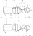
- the Figures 1 and 2 each show a drive system 2, comprising a load 4, which is coupled to a stationary gear 8 via a first shaft 6.
- the transmission 8 in turn is connected to an electrical machine 12 via a second shaft 10.
- the shafts 6 and 10 and the electrical machine 12 the direction of rotation is indicated by arrow R.
- the drive system 2 is penetrated in its longitudinal direction by a longitudinal axis 14, which runs horizontally - the shafts 6 and 10 are therefore perfectly horizontal.
- the two shafts 6 and 10 represent rotating or rotatable components to be analyzed.
- Figure 1 which shows a known and disadvantageous sensor arrangement, shows standard sensors 16 which are arranged on fixed components of the drive system 2 are.
- an additional speed sensor 18 is also arranged on the transmission 8 in order to detect the speed and the angle of rotation of the first shaft 6.
- Figure 2 shows the use of a sensor device 20 according to the invention or a combination smart sensor in the drive system 2.
- a sensor device 20 is arranged in a rotationally fixed manner on each circumference of each shaft 6 and 8.
- the data measured by the combination smart sensors can be transmitted wirelessly (radio, Wi-Fi, Bluetooth, etc.) and/or wired (sliding contact, etc.), whereby Fig. 2 an example of wireless transmission.
- FIG. 3 now shows in a schematically simplified manner the sensor device 20 arranged on the shaft 6, which comprises a housing 22.
- the housing 22 can be arranged reversibly or irreversibly in a rotationally fixed manner on the component and here on the shaft 6 using suitable means.
- Three piezo sensor means 24 A , 24 R , 24 T and a MEMS sensor means 26 are arranged within the housing 22, with only the measuring directions of the sensor means being shown by an arrow for simplification.
- a first piezo sensor means 24 A measures accelerations of the possibly rotating shaft 6 in the axial direction parallel to the longitudinal axis 14.
- Another piezo sensor means 24 R measures accelerations of the possibly rotating shaft 6 in the radial direction and another piezo sensor means 24 T measures accelerations of the possibly rotating shaft 6 in the tangential direction.
- Each of the piezo sensor means 24 A , 24 R , 24 T has a measuring direction aligned orthogonally to the other two piezo sensor means 24 A , 24 R , 24 T.
- the MEMS sensor means 26 measures accelerations of the possibly rotating shaft 6 in the tangential direction and serves as a gravity sensor for determining the spatial position of the sensor device 2 in relation to the shaft 6.
- a storage unit 28 is also arranged in the housing 22, which is used to store the sensor data of the Piezo sensor means 24 A , 24 R , 24 T and the MEMS sensor means 26 is used.
- the storage unit 28 can be accessed via a wireless and/or wired data interface 30 for reading and/or writing data.
- the housing 22 includes an evaluation means 32 for evaluating the sensor data, which is in data connection with the storage unit 28 and the data interface 30.
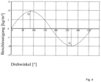
- a mode of operation of the MEMS sensor means 26 is shown in Figure 4 shown as an example using an idealized, perfectly horizontal shaft 6 and using sensor data from a complete rotation of 360°.
- the revolution begins with the MEMS sensor means 26, which is aligned at 9 o'clock with respect to the longitudinal axis 14.
- the shaft 6 rotates in the direction of rotation R, whereby the MEMS sensor means 26 then measures a gravitational acceleration of 9.81 kg/m 2 after a rotation angle of 90° - corresponding to 12 o'clock.
- the MEMS sensor means 26 is now located above the shaft 6, shown in Fig. 3 and indicated by the arrow O.
- the shaft 6 continues to rotate in the direction of rotation R by 90° - corresponding to 3 o'clock - and passes the rotation angle of 180° in actual weightlessness. There is then a negative acceleration due to gravity, whereby at a rotation angle of 270° - corresponding to 6 o'clock - an acceleration due to gravity of - 9.81 kg/m 2 is measured, indicated by the arrow U.
- the full rotation is completed by a further rotation of 90° to the starting position, through which there is also virtual weightlessness.
- the speed measurement and rotation angle measurement carried out by the MEMS sensor means 26 is carried out based on the change in direction of the measured gravity or gravitational acceleration.
- the measured acceleration due to gravity changes during the rotation of the shaft 6 depending on the position of the MEMS sensor means 26 relative to the longitudinal axis 14. This makes it very easy to calculate both the angle of rotation and the speed of rotation of the shaft 6 (a cosine function or a sine function depending on the reference axis: 0° up, down, right or left of the shaft), whereby the number of changes in the acceleration value per unit of time is relevant here.
- So-called time signals are present in S01, which also include the “raw” sensor data. These also include those in Fig. 4 Sine shape shown with its damage caused Superposition vibrations and the speed derived from them and/or the angle of rotation.
- a series of parameters can be formed, such as RMS (Root Mean Square) or crest factor or crest factor.
- the speed variability can be determined, which is the standard deviation of the speed/average value of the speed.
- This parameter is the indicator of torsional dynamics and, for example, in a wind turbine, the indicator of the turbulence intensity of the wind.
- an envelope signal can be generated from the data present in S01, although this necessity depends on the analysis goal.
- the data from SO1 or alternatively the envelope signal from S02 can be made available in S03 in order to use different signals depending on the analysis goal. Regardless of the analysis goal, however, the signals should be filtered for both the time signals and the envelope signal with regard to relevant frequencies.
- the signals can be transmitted into the frequency range in S04.
- a constant-speed component to be analyzed can be transmitted into a frequency range of a frequency spectrum using a fast Fourier transformation (FFT)
- FFT fast Fourier transformation
- a variable-speed component requires order analysis, with the speed or angle of rotation being used for this purpose. Therefore, the speed or angle of rotation detected by MEMS sensor means 26 in a variable-speed component represents an important aspect for vibration analysis.
- the corresponding amplitude spectrum can be created from the result of the FFT or order analysis, which is a periodic or sinusoidal signal. From this spectrum, a condition diagnosis and/or dynamic analysis (natural frequency and/or excitation frequency analysis) can be created in S06 and resonances and/or damage can be identified by comparing them with TARGET values and/or damage patterns.
- the periodic excitation frequencies of imbalances or alignment errors as well as gear damage or advanced bearing damage are particularly suitable for analysis.
- an envelope spectrum can be created from the envelope signal created in S02, to which an FFT was applied in S04.
- a selective spectral analysis can be carried out and a statement can be made about the state of the system and/or one or more components based on damage patterns or abnormal patterns meet.
Landscapes
- Physics & Mathematics (AREA)
- General Physics & Mathematics (AREA)
- Measurement Of Mechanical Vibrations Or Ultrasonic Waves (AREA)
Claims (13)
- Dispositif de capteur pour la saisie d'au moins trois paramètres d'un composant rotatif et à être analysé et configuré pour l'agencement bloqué en rotation sur le composant, le dispositif de capteur comprenant un boîtier (22) et au moins trois moyens de capteur d'accélération disposés dans le boîtier (22), les trois moyens de capteur d'accélération chacun ayant un sens de mesure orthogonal aux deux autres moyens de capteur d'accélération, au moins un des moyens de capteur d'accélération étant configurés comme moyen (26) de MEMS capteur qui est configuré et/ou disponible pour la mesure dans le sens tangentiel et/ou radial du composant, caractérisé en ce que le moyen (26) de MEMS capteur est configuré pour la saisie de la vitesse de rotation et/ou de l'angle de rotation du composant au moyen d'une vibration semblable au sinus ou au cosinus de l'accélération mesurée de la pesanteur.
- Dispositif de capteur selon la revendication 1, dans lequel trois des moyens de capteur d'accélération sont configurés comme moyens de MEMS capteur.
- Dispositif de capteur selon la revendication 1, comprenant trois moyens de capteur d'accélération, deux des trois moyens de capteur d'accélération orientés orthogonalement l'un à l'autre chacun étant configurés comme moyens de capteur piézoélectriques et étant configurés et/ou disponibles pour la mesure dans le sens radial ou axial du composant.
- Dispositif de capteur selon la revendication 1, comprenant un quatrième moyen de capteur d'accélération, les trois moyens de capteur d'accélération orientés orthogonalement l'un à l'autre chacun étant configurés comme moyens de capteur piézoélectriques (24A, 24R, 24T) et le quatrième moyen de capteur d'accélération étant configuré comme moyen (26) de MEMS capteur.
- Dispositif de capteur selon l'une quelconque des revendications précédentes, comprenant au moins un moyen de capteur de distance qui est disposé de préférence dans le boîtier et est configuré et/ou disponible pour la mesure dans le sens radial et/ou axial du composant.
- Dispositif de capteur selon la revendication 5, comprenant un groupe de moyens de capteur, choisi parmi le groupe comprenanta) un moyen de capteur de distance, disponible radialement, et trois moyens de MEMS capteur, chacun disponibles disponible orthogonalement l'un à l'autre tangentiellement et radialement et axialement; oub) deux moyens de capteur de distance, disponibles radialement et axialement, et trois moyens de MEMS capteur, chacun disponibles disponible orthogonalement l'un à l'autre tangentiellement et radialement et axialement; ouc) un moyen de capteur de distance, disponible radialement, et un moyen de MEMS capteur, disponible tangentiellement ou radialement, et trois moyens de capteur piézoélectriques, chacun disponibles disponible orthogonalement l'un à l'autre tangentiellement et radialement et axialement; oud) deux moyens de capteur de distance, disponibles radialement et axialement, et un moyen de MEMS capteur, disponible tangentiellement ou radialement, et trois moyens de capteur piézoélectriques, chacun disponibles disponible orthogonalement l'un à l'autre tangentiellement et radialement et axialement.
- Agencement de capteur pour la saisie d'au moins deux paramètres d'un composant rotatif et à être analysé et configuré pour l'agencement bloqué en rotation sur le composant, le dispositif de capteur comprenant un boîtier et au moins un moyen de capteur d'accélération disposé dans le boîtier, le moyen de capteur d'accélération étant configuré comme moyen de MEMS capteur qui est configuré et/ou disponible pour la mesure dans le sens tangentiel et/ou radial du composant, et un moyen de capteur de distance qui est disposé de préférence dans le boîtier et qui est configuré et/ou disponible pour la mesure dans le sens radial et/ou axial, caractérisé en ce que le moyen (26) de MEMS capteur est configuré pour la saisie de la vitesse de rotation et/ou de l'angle de rotation du composant au moyen d'une vibration semblable au sinus ou au cosinus de l'accélération mesurée de la pesanteur.
- Agencement de capteur selon la revendication 7, comprenant un groupe de moyens de capteur, choisi parmi le groupe comprenanta) un moyen de capteur de distance, disponible radialement, et un moyen de MEMS capteur, disponible tangentiellement ou radialement; oub) deux moyens de capteur de distance, disponibles radialement et axialement, et un moyen de MEMS capteur, disponible tangentiellement ou radialement; orc) un moyen de capteur de distance, disponible radialement, et trois moyens de MEMS capteur, chacun disponibles orthogonalement l'un à l'autre tangentiellement et radialement et axialement; oud) deux moyens de capteur de distance, disponibles radialement et axialement, et trois moyens de MEMS capteur, chacun disponibles orthogonalement l'un à l'autre tangentiellement et radialement et axialement; oue) un moyen de capteur de distance, disponible radialement, et un moyen de MEMS capteur, disponible tangentiellement ou radialement, et trois moyens de capteur piézoélectriques, chacun disponibles orthogonalement l'un à l'autre tangentiellement et radialement et axialement; ouf) deux moyens de capteur de distance, disponibles radialement et axialement, et un moyen de MEMS capteur, disponible tangentiellement ou radialement, et trois moyens de capteur piézoélectriques, chacun disponibles orthogonalement l'un à l'autre tangentiellement et radialement et axialement.
- Dispositif de capteur selon l'une quelconque des revendications 1 à 6, ou agencement de capteur selon la revendication 7 ou la revendication 8, dans lequel l'au moins un moyen de MEMS capteur a une plage de mesure de 0 Hz à 1500 Hz.
- Dispositif de capteur selon l'une quelconque des revendications 3 à 6 et 9, ou agencement de capteur selon la revendication 8 ou la revendication 9, dans lequel l'au moins un moyen de capteur piézoélectrique a une plage de mesure de 0,05 Hz à 10000 Hz.
- Dispositif de capteur selon l'une quelconque des revendications 1 à 6, 9 ou la revendication 10,ou agencement de capteur selon l'une quelconque des revendications 7 à 10, comprenantune unité de stockage (30) pour le stockage des données de capteur de moyens de capteur et/ou une interface de données (28) pour le transfert sans fil et/ou filé des données de capteur de moyens de capteur et/ou un moyen d'évaluation (32) pour l'évaluation de données de capteur de moyen de capteur.
- Système de capteur, comprenant
au moins un composant rotatif et un dispositif de capteur (2) selon l'une quelconque des revendications 1 à 6 ou les revendications 9 à 11 et/ou un agencement de capteur selon l'une quelconque des revendications 7 à 11, qui est/sont disposé(s) sure le(s) composant(s) dans une manière d'être bloquée en rotation. - Utilisation du dispositif de capteur selon l'une quelconque des revendications précédentes ou de l'agencement de capteur selon l'une quelconque des revendications précédentes en utilisant le signal de mesure saisissant par l'au moins un moyen (26) de MEMS capteur orienté et/ou orientable dans le sens tangentiel et/ou radial du composant pour la détermination de la vitesse de rotation et/ou de l'angle de rotation du composant au moyen d'une vibration semblable au sinus ou cosinus de l'accélération mesurée de la pesanteur.
Applications Claiming Priority (1)
| Application Number | Priority Date | Filing Date | Title |
|---|---|---|---|
| DE102018101187 | 2018-01-19 |
Publications (2)
| Publication Number | Publication Date |
|---|---|
| EP3514552A1 EP3514552A1 (fr) | 2019-07-24 |
| EP3514552B1 true EP3514552B1 (fr) | 2024-01-17 |
Family
ID=64650245
Family Applications (1)
| Application Number | Title | Priority Date | Filing Date |
|---|---|---|---|
| EP18210726.8A Active EP3514552B1 (fr) | 2018-01-19 | 2018-12-06 | Dispositif capteur, agencement de capteur, système de capteur ainsi qu'utilisation du dispositif capteur et de l'agencement de capteur |
Country Status (1)
| Country | Link |
|---|---|
| EP (1) | EP3514552B1 (fr) |
Family Cites Families (5)
| Publication number | Priority date | Publication date | Assignee | Title |
|---|---|---|---|---|
| US5101669A (en) * | 1988-07-14 | 1992-04-07 | University Of Hawaii | Multidimensional force sensor |
| JP2001083224A (ja) * | 1999-09-16 | 2001-03-30 | Ddi Corp | 磁界測定方法および装置 |
| JP6143222B2 (ja) * | 2013-03-07 | 2017-06-07 | 三菱重工工作機械株式会社 | 工作機械の異常診断装置及び異常診断方法 |
| DE102014116527B4 (de) * | 2014-11-12 | 2020-01-23 | Andreas Hettich Gmbh & Co. Kg | Zentrifuge und Verfahren zur Erfassung von Unwuchten in der Zentrifuge |
| JP6466357B2 (ja) * | 2016-03-11 | 2019-02-06 | 東芝機械株式会社 | 産業機械および異常検出方法 |
-
2018
- 2018-12-06 EP EP18210726.8A patent/EP3514552B1/fr active Active
Also Published As
| Publication number | Publication date |
|---|---|
| EP3514552A1 (fr) | 2019-07-24 |
Similar Documents
| Publication | Publication Date | Title |
|---|---|---|
| EP2131178B1 (fr) | Procédé de diagnostic pour au moins un roulement à billes, en particulier pour un palier à billes oblique, système de diagnostic correspondant et utilisation d'un tel système de diagnostic | |
| EP3830540B1 (fr) | Procédé de reconnaissance d'un changement de comportement de commande d'un entraînement de vilebrequin d'un véhicule automobile | |
| EP2294287B1 (fr) | Procédé et dispositif de détection de fissures sur des aubes mobiles d'un compresseur | |
| EP2549257B1 (fr) | Procédé de détection de dommages sur des engrenages | |
| DE102006060650A1 (de) | Vorrichtung und Verfahren zur berührungslosen Schaufelschwingungsmessung | |
| EP3581328B1 (fr) | Unité de machine-outil à contrôle du voile et procédé de vérification de l'état de serrage | |
| WO2013064209A2 (fr) | Procédé, unité de calcul, et dispositif de surveillance d'une chaîne cinématique | |
| DE19727114A1 (de) | Verfahren zur Ermittlung und Darstellung von Spektren für Schwingungssignale | |
| DE102007003867A1 (de) | Verfahren und Vorrichtung zum Überwachen eines eine hochelastische Kupplung aufweisenden Antriebsstrangs | |
| EP3243015B1 (fr) | Système et procédé de mesure permettant de détecter des grandeurs sur les porte-satellites d'un train planétaire | |
| EP3447318A1 (fr) | Dispositif et procédé de surveillance d'un dispositif doté d'un dispositif de palier lisse | |
| EP2169224A2 (fr) | Procédé pour surveiller un composant d'une chaîne cinématique d'une éolienne | |
| DE112017000950T5 (de) | Abnormalitäts-Diagnosevorrichtung und Abnormalitäts-Diagnoseverfahren | |
| WO2016091933A1 (fr) | Procédé et dispositif pour surveiller une éolienne | |
| EP3268635A1 (fr) | Engrenage planétaire | |
| EP3514552B1 (fr) | Dispositif capteur, agencement de capteur, système de capteur ainsi qu'utilisation du dispositif capteur et de l'agencement de capteur | |
| DE102011116561A1 (de) | Drehmomentmesswelle und Verfahren zur Messung eines Drehmomentes | |
| EP2203730A2 (fr) | Dispositif de mesure destiné à déterminer l'état de fonctionnement d'un arbre, procédé et ensemble arbre muni du dispositif de mesure | |
| EP3517924A1 (fr) | Surveillance d'état du vilebrequin dans un moteur à combustion | |
| DE102012015457A1 (de) | Vorrichtung und Verfahren zur Verschleißbestimmung | |
| Bourdon et al. | Estimation of the size of a spall defect on a rolling bearing outer ring using Instantaneous Angular Speed measurements | |
| DE102012107590A1 (de) | Verfahren und Vorrichtung zum Ermitteln von Umgebungseinflüssen bei einer Schwingungen messenden Auswuchtmaschine | |
| EP3492735B1 (fr) | Procédé et dispositif de détermination d'une force statique d'un rotor d'une éolienne | |
| DE102009009714A1 (de) | Vorrichtung und Verfahren zur Drehmomentmessung an einer Turbinenwelle | |
| EP3996259A1 (fr) | Procédé de surveillance du fonctionnement d'un composant technique d'entraînement |
Legal Events
| Date | Code | Title | Description |
|---|---|---|---|
| PUAI | Public reference made under article 153(3) epc to a published international application that has entered the european phase |
Free format text: ORIGINAL CODE: 0009012 |
|
| STAA | Information on the status of an ep patent application or granted ep patent |
Free format text: STATUS: THE APPLICATION HAS BEEN PUBLISHED |
|
| AK | Designated contracting states |
Kind code of ref document: A1 Designated state(s): AL AT BE BG CH CY CZ DE DK EE ES FI FR GB GR HR HU IE IS IT LI LT LU LV MC MK MT NL NO PL PT RO RS SE SI SK SM TR |
|
| AX | Request for extension of the european patent |
Extension state: BA ME |
|
| STAA | Information on the status of an ep patent application or granted ep patent |
Free format text: STATUS: REQUEST FOR EXAMINATION WAS MADE |
|
| 17P | Request for examination filed |
Effective date: 20200123 |
|
| RBV | Designated contracting states (corrected) |
Designated state(s): AL AT BE BG CH CY CZ DE DK EE ES FI FR GB GR HR HU IE IS IT LI LT LU LV MC MK MT NL NO PL PT RO RS SE SI SK SM TR |
|
| R17P | Request for examination filed (corrected) |
Effective date: 20200123 |
|
| STAA | Information on the status of an ep patent application or granted ep patent |
Free format text: STATUS: EXAMINATION IS IN PROGRESS |
|
| 17Q | First examination report despatched |
Effective date: 20230217 |
|
| GRAP | Despatch of communication of intention to grant a patent |
Free format text: ORIGINAL CODE: EPIDOSNIGR1 |
|
| STAA | Information on the status of an ep patent application or granted ep patent |
Free format text: STATUS: GRANT OF PATENT IS INTENDED |
|
| INTG | Intention to grant announced |
Effective date: 20230926 |
|
| GRAS | Grant fee paid |
Free format text: ORIGINAL CODE: EPIDOSNIGR3 |
|
| GRAA | (expected) grant |
Free format text: ORIGINAL CODE: 0009210 |
|
| STAA | Information on the status of an ep patent application or granted ep patent |
Free format text: STATUS: THE PATENT HAS BEEN GRANTED |
|
| AK | Designated contracting states |
Kind code of ref document: B1 Designated state(s): AL AT BE BG CH CY CZ DE DK EE ES FI FR GB GR HR HU IE IS IT LI LT LU LV MC MK MT NL NO PL PT RO RS SE SI SK SM TR |
|
| REG | Reference to a national code |
Ref country code: GB Ref legal event code: FG4D Free format text: NOT ENGLISH |
|
| REG | Reference to a national code |
Ref country code: DE Ref legal event code: R096 Ref document number: 502018013991 Country of ref document: DE |
|
| REG | Reference to a national code |
Ref country code: CH Ref legal event code: EP |
|
| REG | Reference to a national code |
Ref country code: IE Ref legal event code: FG4D Free format text: LANGUAGE OF EP DOCUMENT: GERMAN |
|
| REG | Reference to a national code |
Ref country code: SE Ref legal event code: TRGR |
|
| REG | Reference to a national code |
Ref country code: LT Ref legal event code: MG9D |
|
| REG | Reference to a national code |
Ref country code: NL Ref legal event code: MP Effective date: 20240117 |
|
| PG25 | Lapsed in a contracting state [announced via postgrant information from national office to epo] |
Ref country code: NL Free format text: LAPSE BECAUSE OF FAILURE TO SUBMIT A TRANSLATION OF THE DESCRIPTION OR TO PAY THE FEE WITHIN THE PRESCRIBED TIME-LIMIT Effective date: 20240117 |
|
| PG25 | Lapsed in a contracting state [announced via postgrant information from national office to epo] |
Ref country code: NL Free format text: LAPSE BECAUSE OF FAILURE TO SUBMIT A TRANSLATION OF THE DESCRIPTION OR TO PAY THE FEE WITHIN THE PRESCRIBED TIME-LIMIT Effective date: 20240117 |
|
| PG25 | Lapsed in a contracting state [announced via postgrant information from national office to epo] |
Ref country code: IS Free format text: LAPSE BECAUSE OF FAILURE TO SUBMIT A TRANSLATION OF THE DESCRIPTION OR TO PAY THE FEE WITHIN THE PRESCRIBED TIME-LIMIT Effective date: 20240517 |
|
| PG25 | Lapsed in a contracting state [announced via postgrant information from national office to epo] |
Ref country code: LT Free format text: LAPSE BECAUSE OF FAILURE TO SUBMIT A TRANSLATION OF THE DESCRIPTION OR TO PAY THE FEE WITHIN THE PRESCRIBED TIME-LIMIT Effective date: 20240117 |
|
| PG25 | Lapsed in a contracting state [announced via postgrant information from national office to epo] |
Ref country code: GR Free format text: LAPSE BECAUSE OF FAILURE TO SUBMIT A TRANSLATION OF THE DESCRIPTION OR TO PAY THE FEE WITHIN THE PRESCRIBED TIME-LIMIT Effective date: 20240418 |
|
| PG25 | Lapsed in a contracting state [announced via postgrant information from national office to epo] |
Ref country code: HR Free format text: LAPSE BECAUSE OF FAILURE TO SUBMIT A TRANSLATION OF THE DESCRIPTION OR TO PAY THE FEE WITHIN THE PRESCRIBED TIME-LIMIT Effective date: 20240117 Ref country code: RS Free format text: LAPSE BECAUSE OF FAILURE TO SUBMIT A TRANSLATION OF THE DESCRIPTION OR TO PAY THE FEE WITHIN THE PRESCRIBED TIME-LIMIT Effective date: 20240417 |
|
| PG25 | Lapsed in a contracting state [announced via postgrant information from national office to epo] |
Ref country code: ES Free format text: LAPSE BECAUSE OF FAILURE TO SUBMIT A TRANSLATION OF THE DESCRIPTION OR TO PAY THE FEE WITHIN THE PRESCRIBED TIME-LIMIT Effective date: 20240117 |
|
| PG25 | Lapsed in a contracting state [announced via postgrant information from national office to epo] |
Ref country code: RS Free format text: LAPSE BECAUSE OF FAILURE TO SUBMIT A TRANSLATION OF THE DESCRIPTION OR TO PAY THE FEE WITHIN THE PRESCRIBED TIME-LIMIT Effective date: 20240417 Ref country code: NO Free format text: LAPSE BECAUSE OF FAILURE TO SUBMIT A TRANSLATION OF THE DESCRIPTION OR TO PAY THE FEE WITHIN THE PRESCRIBED TIME-LIMIT Effective date: 20240417 Ref country code: LT Free format text: LAPSE BECAUSE OF FAILURE TO SUBMIT A TRANSLATION OF THE DESCRIPTION OR TO PAY THE FEE WITHIN THE PRESCRIBED TIME-LIMIT Effective date: 20240117 Ref country code: IS Free format text: LAPSE BECAUSE OF FAILURE TO SUBMIT A TRANSLATION OF THE DESCRIPTION OR TO PAY THE FEE WITHIN THE PRESCRIBED TIME-LIMIT Effective date: 20240517 Ref country code: HR Free format text: LAPSE BECAUSE OF FAILURE TO SUBMIT A TRANSLATION OF THE DESCRIPTION OR TO PAY THE FEE WITHIN THE PRESCRIBED TIME-LIMIT Effective date: 20240117 Ref country code: GR Free format text: LAPSE BECAUSE OF FAILURE TO SUBMIT A TRANSLATION OF THE DESCRIPTION OR TO PAY THE FEE WITHIN THE PRESCRIBED TIME-LIMIT Effective date: 20240418 Ref country code: FI Free format text: LAPSE BECAUSE OF FAILURE TO SUBMIT A TRANSLATION OF THE DESCRIPTION OR TO PAY THE FEE WITHIN THE PRESCRIBED TIME-LIMIT Effective date: 20240117 Ref country code: ES Free format text: LAPSE BECAUSE OF FAILURE TO SUBMIT A TRANSLATION OF THE DESCRIPTION OR TO PAY THE FEE WITHIN THE PRESCRIBED TIME-LIMIT Effective date: 20240117 Ref country code: BG Free format text: LAPSE BECAUSE OF FAILURE TO SUBMIT A TRANSLATION OF THE DESCRIPTION OR TO PAY THE FEE WITHIN THE PRESCRIBED TIME-LIMIT Effective date: 20240117 |
|
| PG25 | Lapsed in a contracting state [announced via postgrant information from national office to epo] |
Ref country code: PL Free format text: LAPSE BECAUSE OF FAILURE TO SUBMIT A TRANSLATION OF THE DESCRIPTION OR TO PAY THE FEE WITHIN THE PRESCRIBED TIME-LIMIT Effective date: 20240117 Ref country code: PT Free format text: LAPSE BECAUSE OF FAILURE TO SUBMIT A TRANSLATION OF THE DESCRIPTION OR TO PAY THE FEE WITHIN THE PRESCRIBED TIME-LIMIT Effective date: 20240517 |
|
| PG25 | Lapsed in a contracting state [announced via postgrant information from national office to epo] |
Ref country code: PT Free format text: LAPSE BECAUSE OF FAILURE TO SUBMIT A TRANSLATION OF THE DESCRIPTION OR TO PAY THE FEE WITHIN THE PRESCRIBED TIME-LIMIT Effective date: 20240517 Ref country code: PL Free format text: LAPSE BECAUSE OF FAILURE TO SUBMIT A TRANSLATION OF THE DESCRIPTION OR TO PAY THE FEE WITHIN THE PRESCRIBED TIME-LIMIT Effective date: 20240117 Ref country code: LV Free format text: LAPSE BECAUSE OF FAILURE TO SUBMIT A TRANSLATION OF THE DESCRIPTION OR TO PAY THE FEE WITHIN THE PRESCRIBED TIME-LIMIT Effective date: 20240117 |
|
| PG25 | Lapsed in a contracting state [announced via postgrant information from national office to epo] |
Ref country code: DK Free format text: LAPSE BECAUSE OF FAILURE TO SUBMIT A TRANSLATION OF THE DESCRIPTION OR TO PAY THE FEE WITHIN THE PRESCRIBED TIME-LIMIT Effective date: 20240117 |
|
| PG25 | Lapsed in a contracting state [announced via postgrant information from national office to epo] |
Ref country code: SM Free format text: LAPSE BECAUSE OF FAILURE TO SUBMIT A TRANSLATION OF THE DESCRIPTION OR TO PAY THE FEE WITHIN THE PRESCRIBED TIME-LIMIT Effective date: 20240117 |
|
| REG | Reference to a national code |
Ref country code: DE Ref legal event code: R097 Ref document number: 502018013991 Country of ref document: DE |
|
| PG25 | Lapsed in a contracting state [announced via postgrant information from national office to epo] |
Ref country code: EE Free format text: LAPSE BECAUSE OF FAILURE TO SUBMIT A TRANSLATION OF THE DESCRIPTION OR TO PAY THE FEE WITHIN THE PRESCRIBED TIME-LIMIT Effective date: 20240117 Ref country code: CZ Free format text: LAPSE BECAUSE OF FAILURE TO SUBMIT A TRANSLATION OF THE DESCRIPTION OR TO PAY THE FEE WITHIN THE PRESCRIBED TIME-LIMIT Effective date: 20240117 |
|
| PG25 | Lapsed in a contracting state [announced via postgrant information from national office to epo] |
Ref country code: SK Free format text: LAPSE BECAUSE OF FAILURE TO SUBMIT A TRANSLATION OF THE DESCRIPTION OR TO PAY THE FEE WITHIN THE PRESCRIBED TIME-LIMIT Effective date: 20240117 |
|
| PG25 | Lapsed in a contracting state [announced via postgrant information from national office to epo] |
Ref country code: SM Free format text: LAPSE BECAUSE OF FAILURE TO SUBMIT A TRANSLATION OF THE DESCRIPTION OR TO PAY THE FEE WITHIN THE PRESCRIBED TIME-LIMIT Effective date: 20240117 Ref country code: SK Free format text: LAPSE BECAUSE OF FAILURE TO SUBMIT A TRANSLATION OF THE DESCRIPTION OR TO PAY THE FEE WITHIN THE PRESCRIBED TIME-LIMIT Effective date: 20240117 Ref country code: RO Free format text: LAPSE BECAUSE OF FAILURE TO SUBMIT A TRANSLATION OF THE DESCRIPTION OR TO PAY THE FEE WITHIN THE PRESCRIBED TIME-LIMIT Effective date: 20240117 Ref country code: EE Free format text: LAPSE BECAUSE OF FAILURE TO SUBMIT A TRANSLATION OF THE DESCRIPTION OR TO PAY THE FEE WITHIN THE PRESCRIBED TIME-LIMIT Effective date: 20240117 Ref country code: DK Free format text: LAPSE BECAUSE OF FAILURE TO SUBMIT A TRANSLATION OF THE DESCRIPTION OR TO PAY THE FEE WITHIN THE PRESCRIBED TIME-LIMIT Effective date: 20240117 Ref country code: CZ Free format text: LAPSE BECAUSE OF FAILURE TO SUBMIT A TRANSLATION OF THE DESCRIPTION OR TO PAY THE FEE WITHIN THE PRESCRIBED TIME-LIMIT Effective date: 20240117 |
|
| PLBE | No opposition filed within time limit |
Free format text: ORIGINAL CODE: 0009261 |
|
| STAA | Information on the status of an ep patent application or granted ep patent |
Free format text: STATUS: NO OPPOSITION FILED WITHIN TIME LIMIT |
|
| PG25 | Lapsed in a contracting state [announced via postgrant information from national office to epo] |
Ref country code: IT Free format text: LAPSE BECAUSE OF FAILURE TO SUBMIT A TRANSLATION OF THE DESCRIPTION OR TO PAY THE FEE WITHIN THE PRESCRIBED TIME-LIMIT Effective date: 20240117 |
|
| 26N | No opposition filed |
Effective date: 20241018 |
|
| PG25 | Lapsed in a contracting state [announced via postgrant information from national office to epo] |
Ref country code: IT Free format text: LAPSE BECAUSE OF FAILURE TO SUBMIT A TRANSLATION OF THE DESCRIPTION OR TO PAY THE FEE WITHIN THE PRESCRIBED TIME-LIMIT Effective date: 20240117 |
|
| PG25 | Lapsed in a contracting state [announced via postgrant information from national office to epo] |
Ref country code: SI Free format text: LAPSE BECAUSE OF FAILURE TO SUBMIT A TRANSLATION OF THE DESCRIPTION OR TO PAY THE FEE WITHIN THE PRESCRIBED TIME-LIMIT Effective date: 20240117 |
|
| PG25 | Lapsed in a contracting state [announced via postgrant information from national office to epo] |
Ref country code: MC Free format text: LAPSE BECAUSE OF FAILURE TO SUBMIT A TRANSLATION OF THE DESCRIPTION OR TO PAY THE FEE WITHIN THE PRESCRIBED TIME-LIMIT Effective date: 20240117 |
|
| REG | Reference to a national code |
Ref country code: CH Ref legal event code: PL |
|
| PG25 | Lapsed in a contracting state [announced via postgrant information from national office to epo] |
Ref country code: LU Free format text: LAPSE BECAUSE OF NON-PAYMENT OF DUE FEES Effective date: 20241206 |
|
| REG | Reference to a national code |
Ref country code: BE Ref legal event code: MM Effective date: 20241231 |
|
| PG25 | Lapsed in a contracting state [announced via postgrant information from national office to epo] |
Ref country code: BE Free format text: LAPSE BECAUSE OF NON-PAYMENT OF DUE FEES Effective date: 20241231 |
|
| PG25 | Lapsed in a contracting state [announced via postgrant information from national office to epo] |
Ref country code: FR Free format text: LAPSE BECAUSE OF NON-PAYMENT OF DUE FEES Effective date: 20241231 |
|
| PG25 | Lapsed in a contracting state [announced via postgrant information from national office to epo] |
Ref country code: CH Free format text: LAPSE BECAUSE OF NON-PAYMENT OF DUE FEES Effective date: 20241231 |
|
| PG25 | Lapsed in a contracting state [announced via postgrant information from national office to epo] |
Ref country code: IE Free format text: LAPSE BECAUSE OF NON-PAYMENT OF DUE FEES Effective date: 20241206 |
|
| PGFP | Annual fee paid to national office [announced via postgrant information from national office to epo] |
Ref country code: GB Payment date: 20251218 Year of fee payment: 8 |
|
| PGFP | Annual fee paid to national office [announced via postgrant information from national office to epo] |
Ref country code: AT Payment date: 20251215 Year of fee payment: 8 |
|
| PGFP | Annual fee paid to national office [announced via postgrant information from national office to epo] |
Ref country code: SE Payment date: 20251217 Year of fee payment: 8 |
|
| REG | Reference to a national code |
Ref country code: DE Ref legal event code: R081 Ref document number: 502018013991 Country of ref document: DE Owner name: MML SERVICE SOLUTIONS GMBH, DE Free format text: FORMER OWNER: MML SOLUTIONS GMBH, 46487 WESEL, DE |
|
| PG25 | Lapsed in a contracting state [announced via postgrant information from national office to epo] |
Ref country code: CY Free format text: LAPSE BECAUSE OF FAILURE TO SUBMIT A TRANSLATION OF THE DESCRIPTION OR TO PAY THE FEE WITHIN THE PRESCRIBED TIME-LIMIT; INVALID AB INITIO Effective date: 20181206 |
|
| PGFP | Annual fee paid to national office [announced via postgrant information from national office to epo] |
Ref country code: DE Payment date: 20260219 Year of fee payment: 8 |
|
| REG | Reference to a national code |
Ref country code: GB Ref legal event code: 732E Free format text: REGISTERED BETWEEN 20260326 AND 20260401 |