EP3514552B1 - Sensor device, sensor arrangement, sensor system and a use of the sensor device and sensor arrangement - Google Patents
Sensor device, sensor arrangement, sensor system and a use of the sensor device and sensor arrangement Download PDFInfo
- Publication number
- EP3514552B1 EP3514552B1 EP18210726.8A EP18210726A EP3514552B1 EP 3514552 B1 EP3514552 B1 EP 3514552B1 EP 18210726 A EP18210726 A EP 18210726A EP 3514552 B1 EP3514552 B1 EP 3514552B1
- Authority
- EP
- European Patent Office
- Prior art keywords
- sensor means
- sensor
- disposable
- radially
- component
- Prior art date
- Legal status (The legal status is an assumption and is not a legal conclusion. Google has not performed a legal analysis and makes no representation as to the accuracy of the status listed.)
- Active
Links
Images


Classifications
-
- G—PHYSICS
- G01—MEASURING; TESTING
- G01P—MEASURING LINEAR OR ANGULAR SPEED, ACCELERATION, DECELERATION, OR SHOCK; INDICATING PRESENCE, ABSENCE, OR DIRECTION, OF MOVEMENT
- G01P15/00—Measuring acceleration; Measuring deceleration; Measuring shock, i.e. sudden change of acceleration
- G01P15/18—Measuring acceleration; Measuring deceleration; Measuring shock, i.e. sudden change of acceleration in two or more dimensions
-
- G—PHYSICS
- G01—MEASURING; TESTING
- G01M—TESTING STATIC OR DYNAMIC BALANCE OF MACHINES OR STRUCTURES; TESTING OF STRUCTURES OR APPARATUS, NOT OTHERWISE PROVIDED FOR
- G01M1/00—Testing static or dynamic balance of machines or structures
- G01M1/14—Determining imbalance
Definitions
- the invention relates to a sensor device, a sensor arrangement, a sensor system and the use thereof for determining a status diagnosis and/or for creating a dynamic analysis of a rotatable component and/or the associated system and the environmental conditions.
- sensors that are arranged on a separate, fixed component have been used to analyze the corresponding components.
- the vibration signals are usually recorded on a housing. These signals are analyzed depending on the operating mode of the system (with fixed speed or variable speed) without or with the speed signal in order to detect possible abnormalities in a component (using natural frequency and/or excitation frequency analysis), such abnormalities, for example, unwanted resonances, damage or other defects such as imbalances or other undesirable vibrations.
- the analysis can take place over the entire lifespan of a system or only temporarily.
- Triaxial measuring sensors are also known, which either exclusively have piezo sensors or MEMS sensors (micro-electro-mechanical system). These sensors are attached to fixed structural components, although there is no evaluation intelligence in the sensor. In addition, due to the arrangement, they cannot calculate speeds. However, due to their design and measuring points, these triaxial sensors do not provide comprehensive component information.
- the natural frequencies, the excitation of the natural vibration and the kinematic frequency depend on the speed of the component, which is why the speed must also be recorded in order to be able to make a meaningful diagnosis of the condition and/or to carry out a dynamic analysis.
- optical sensors are usually used, which in turn are arranged at other measuring points.
- a disadvantage of the previous measurement is that it is carried out on fixed structural components - such as a housing - which inevitably causes additional challenges due to the existing natural frequencies of these components. This makes the condition diagnosis more difficult despite the use of different filter options.
- the natural frequencies of the structural components drown out the damage frequencies sought, making it difficult to clearly define or filter out a frequency that indicates damage.
- the inherent damping of the fixed structural component suppresses the excitation levels of the damage frequencies sought from the rotatable components to be analyzed.
- sensor arrangements are known from the prior art, for example, which have an acceleration sensor in a housing for the acceleration measurement of a component to be analyzed and a distance sensor in a separate housing for air gap measurement in one electrical machine, such as a generator. An air gap between the rotor and stator should be measured there.
- One Unequal air gap size over one revolution of the component leads to dynamic problems in the electrical machine, unwanted vibration and unwanted noise emissions.
- previous sensor arrangements are suitable for determining the position of the unequal air gap, this requires a separate synchronous measurement of the angle of rotation using an additional, separate sensor.
- the invention is therefore based on the object of creating a sensor device, a use of the sensor device, a sensor arrangement and a sensor system which overcome the problems of the prior art, in particular in that a simplified and more precise determination of the diagnosis of a rotatable component is possible Use of the smallest possible number of sensors and measuring points as part of, for example, natural frequency and/or excitation frequency analysis and machine condition diagnosis.
- a sensor device designed for detection of at least three parameters of a component to be analyzed and capable of rotation and for rotationally fixed arrangement on the component, comprising a housing, and at least three acceleration sensor means arranged in the housing, each of which has a measuring direction arranged orthogonally to the other two acceleration sensor means, at least one of the acceleration sensor means as MEMS sensor means is formed, which is designed and / or arranged for measurement in the tangential and / or radial direction of the component.
- the at least one acceleration sensor means is set up to detect the speed and/or the angle of rotation of the component based on a sine- or cosine-like oscillation of the measured acceleration due to gravity.
- the invention is based on the idea that a single sensor device or a single combination smart sensor is designed, within the housing of which sufficient sensor means are present to carry out a status diagnosis as well as a natural frequency and/or resonance and/or excitation frequency analysis (e.g. start-up and run-down test ).
- This combination smart sensor can be arranged on the component to be analyzed itself, whereby the component to be analyzed can be, for example, a rotatable or rotating shaft or another rotatable or rotating component, such as a toothed ring gear, rotor of an electric motor, a rolling bearing, or even a rotor of a electric machine. This means that only a single sensor device is required at a single measuring point.
- the combination smart sensor now provides that, in addition to the acceleration sensor means, at least one MEMS sensor means is also integrated into a unit as a gravity sensor.
- the advantage is that the combination smart sensor, thanks to its arrangement directly on the component to be analyzed, can record all vibrations without damping and much more clearly than was possible with the previously known system. There is significantly less signal noise.
- the vibrations in a gearbox as the component to be analyzed are mainly caused by the circumferential force, which accounts for up to 80% of the total force caused by torque. This allows, in particular, what is to be analyzed Component - for example a shaft - prevailing torsional vibrations can be detected in an advantageous manner.
- the MEMS sensor means is used to determine the spatial position of the sensor device in relation to the component to be analyzed.
- the spatial position of the sensor device is therefore known for each vibration.
- the combination smart sensor can also be easily retrofitted into existing systems as it only needs to be arranged at a single measuring point. For example, it can be arranged there permanently or only for a limited time for a measurement period.
- the sensor means of the combination smart sensor can detect at least three parameters, a force component being considered as a parameter.
- the sensor means can be arranged in the housing in such a way that - similar to a three-dimensional Cartesian coordinate system - they measure in three spatial directions, namely axial, radial and tangential with respect to the component to be analyzed and thus detect three parameters.
- the measuring direction of the MEMS sensor device should be tangential to the component to be analyzed in order to be able to record the speed of the shaft via the fluctuations in the gravitational acceleration measurement.
- the tangential measurement signal not only contains information about the acceleration due to gravity - it is also superimposed by other vibrations.
- the speed and/or the rotation angle is thus detected with the MEMS sensor means and the vibrations (vibration speed and/or vibration acceleration) are detected with the MEMS sensor means and with the other two acceleration sensor means.
- three of the acceleration sensor means are designed as MEMS sensor means. They preferably have a measuring range of 0 Hz to 1500 Hz. With this version, a system can be analyzed in which low frequencies occur in the range from 0 Hz to 1500 Hz. This is sufficient for many applications. An example of this is the imbalance of a slow-moving shaft.
- three acceleration sensor means are provided, with two of the three acceleration sensor means aligned orthogonally to one another each being designed as piezo sensor means and being designed and/or arranged for measurement in the radial or axial direction of the component.
- the third acceleration sensor means is designed as a MEMS sensor means, with the piezo sensor means preferably having a measuring range of 0.05 Hz to 10,000 Hz.
- the sensor device comprises a fourth acceleration sensor means, wherein the three acceleration sensor means aligned orthogonally to one another are each designed as piezo sensor means and the fourth acceleration sensor means is designed as the MEMS sensor means, wherein preferably the piezo sensor means have a measuring range from 0.05 Hz to 10000 Hz.
- Piezo sensing means can measure three main effects, namely transverse, longitudinal and shear effects. These acceleration sensors can be combined within a single housing. Piezo sensor means are basically used to detect higher frequencies.
- the MEMS sensor reacts very sensitively to fluctuations in acceleration, especially to changes in the measured acceleration due to gravity.
- this comprises at least one distance sensor means, preferably arranged in the housing, which is designed and/or arranged for measuring in the radial and/or axial direction of the component.
- the distance sensor means takes a distance measurement or path measurement, for example between rotors and stator of an electrical machine to measure an air gap. Air gap fluctuations can have a serious impact, especially with regard to the trouble-free functioning of electrical machines. Such air gap fluctuations are regularly observed, for example, in large generators.
- the combination of the two measurement signals (speed/angle of rotation from the MEMS sensor means and air gap size from the distance sensor means) in a single housing is advantageous.
- the distance sensor means therefore measures different air gap sizes over a full revolution of the component.
- the distance data can be represented spatially and the unsynchronization can be localized.
- only a single sensor housing is required. With the invention, not only can the vibrations of the component be analyzed, but their cause (air gap) can also be researched.
- the distance sensor means can be, for example, an eddy current sensor or a capacitive sensor.
- Measuring in the axial direction can be useful if there are or are to be expected axial displacements due to the special windings or the use of certain types of bearings in generators. Further advantages of the individual bundles result from the rest of the description.
- a sensor arrangement for detecting at least two parameters of a component to be analyzed and capable of rotation and designed for rotationally fixed arrangement on the component, comprising a housing and at least one acceleration sensor means arranged in the housing, which is designed as a MEMS sensor means which is used for measurement is formed and/or arranged in the tangential and/or radial direction of the component, as well as a distance sensor means preferably arranged in the housing, which is designed and/or arranged for measurement in the radial and/or axial direction of the component.
- the at least one acceleration sensor means is set up to detect the speed and/or the angle of rotation of the component based on a sine- or cosine-like oscillation of the measured acceleration due to gravity.
- a combination of the two measurement signals (speed/angle of rotation from the MEMS sensor means and air gap size from the distance sensor means) is realized in a single housing.
- the distance sensor means therefore measures different air gap sizes over a full revolution of the component. If the MEMS data is now added to this distance data, the distance data can be represented spatially and the unsynchronization can be localized. In addition, only a single sensor housing is required. With the invention, not only can the vibrations of the component be analyzed, but their cause (air gap) can also be researched.
- the distance sensor means can be, for example, an eddy current sensor or a capacitive sensor. Further advantages of the individual bundles result from the rest of the description.
- the at least one MEMS sensor means has a measuring range of 0 Hz to 1500 Hz.
- the at least one piezo sensor means has a measuring range of 0.05 Hz to 10,000 Hz.
- a storage unit for storing sensor data from the sensor means and/or a data interface for wireless and/or wired transmission of sensor data from the sensor means and/or an evaluation means for evaluating the sensor data from the sensor means.
- the sensor data can, for example, be stored in the memory and only read and analyzed after a defined measurement period, for example after the combination smart sensor has been removed from the component.
- the sensor data can also be sent to a stationary computing unit via a data interface for evaluation based on different aspects of machine diagnosis and/or machine dynamics.
- evaluation means such as microprocessors and/or microcontrollers, are arranged in the housing of the sensor device, so that an evaluation can take place in the sensor device itself, with the results of the evaluation or the status diagnosis then being sent to one via the interface can be transmitted to external data recipients.
- the evaluation means can, for example, process the distance sensor data in combination with the speed and/or rotation angle detection.
- a sensor system comprising at least one rotatable component and a sensor device according to the invention and/or a sensor arrangement according to the invention, which is/are arranged in a rotationally fixed manner on the component(s).
- the sensor device and the sensor arrangement are arranged such that the MEMS sensor means measures in a tangential or radial direction with respect to the component.
- the sensor system essentially has the advantages mentioned above with regard to the sensor device and the sensor arrangement, to which reference is hereby made.
- the sensor device according to the invention or the sensor arrangement according to the invention using the at least one which can be aligned in the tangential and/or radial direction of the component and/or aligned MEMS sensor means (26) to determine the speed and/or angle of rotation of the component based on a sine- or cosine-like oscillation of the measured acceleration due to gravity.
- aspects of machine dynamics and condition diagnosis can include: Strong torsional vibrations with the natural frequency of the system (unsuitable control; need for damping measures), unbalance, alignment errors, strong tracking effects (for example in wind turbines due to higher wind turbulence and the resulting increased speed variability), bearing damage, gear damage, uneven load distribution the individual planet gears in a gearbox, generator abnormalities based on the characteristic frequencies of the magnetic forces, etc.
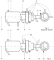
- the Figures 1 and 2 each show a drive system 2, comprising a load 4, which is coupled to a stationary gear 8 via a first shaft 6.
- the transmission 8 in turn is connected to an electrical machine 12 via a second shaft 10.
- the shafts 6 and 10 and the electrical machine 12 the direction of rotation is indicated by arrow R.
- the drive system 2 is penetrated in its longitudinal direction by a longitudinal axis 14, which runs horizontally - the shafts 6 and 10 are therefore perfectly horizontal.
- the two shafts 6 and 10 represent rotating or rotatable components to be analyzed.
- Figure 1 which shows a known and disadvantageous sensor arrangement, shows standard sensors 16 which are arranged on fixed components of the drive system 2 are.
- an additional speed sensor 18 is also arranged on the transmission 8 in order to detect the speed and the angle of rotation of the first shaft 6.
- Figure 2 shows the use of a sensor device 20 according to the invention or a combination smart sensor in the drive system 2.
- a sensor device 20 is arranged in a rotationally fixed manner on each circumference of each shaft 6 and 8.
- the data measured by the combination smart sensors can be transmitted wirelessly (radio, Wi-Fi, Bluetooth, etc.) and/or wired (sliding contact, etc.), whereby Fig. 2 an example of wireless transmission.
- FIG. 3 now shows in a schematically simplified manner the sensor device 20 arranged on the shaft 6, which comprises a housing 22.
- the housing 22 can be arranged reversibly or irreversibly in a rotationally fixed manner on the component and here on the shaft 6 using suitable means.
- Three piezo sensor means 24 A , 24 R , 24 T and a MEMS sensor means 26 are arranged within the housing 22, with only the measuring directions of the sensor means being shown by an arrow for simplification.
- a first piezo sensor means 24 A measures accelerations of the possibly rotating shaft 6 in the axial direction parallel to the longitudinal axis 14.
- Another piezo sensor means 24 R measures accelerations of the possibly rotating shaft 6 in the radial direction and another piezo sensor means 24 T measures accelerations of the possibly rotating shaft 6 in the tangential direction.
- Each of the piezo sensor means 24 A , 24 R , 24 T has a measuring direction aligned orthogonally to the other two piezo sensor means 24 A , 24 R , 24 T.
- the MEMS sensor means 26 measures accelerations of the possibly rotating shaft 6 in the tangential direction and serves as a gravity sensor for determining the spatial position of the sensor device 2 in relation to the shaft 6.
- a storage unit 28 is also arranged in the housing 22, which is used to store the sensor data of the Piezo sensor means 24 A , 24 R , 24 T and the MEMS sensor means 26 is used.
- the storage unit 28 can be accessed via a wireless and/or wired data interface 30 for reading and/or writing data.
- the housing 22 includes an evaluation means 32 for evaluating the sensor data, which is in data connection with the storage unit 28 and the data interface 30.
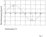
- a mode of operation of the MEMS sensor means 26 is shown in Figure 4 shown as an example using an idealized, perfectly horizontal shaft 6 and using sensor data from a complete rotation of 360°.
- the revolution begins with the MEMS sensor means 26, which is aligned at 9 o'clock with respect to the longitudinal axis 14.
- the shaft 6 rotates in the direction of rotation R, whereby the MEMS sensor means 26 then measures a gravitational acceleration of 9.81 kg/m 2 after a rotation angle of 90° - corresponding to 12 o'clock.
- the MEMS sensor means 26 is now located above the shaft 6, shown in Fig. 3 and indicated by the arrow O.
- the shaft 6 continues to rotate in the direction of rotation R by 90° - corresponding to 3 o'clock - and passes the rotation angle of 180° in actual weightlessness. There is then a negative acceleration due to gravity, whereby at a rotation angle of 270° - corresponding to 6 o'clock - an acceleration due to gravity of - 9.81 kg/m 2 is measured, indicated by the arrow U.
- the full rotation is completed by a further rotation of 90° to the starting position, through which there is also virtual weightlessness.
- the speed measurement and rotation angle measurement carried out by the MEMS sensor means 26 is carried out based on the change in direction of the measured gravity or gravitational acceleration.
- the measured acceleration due to gravity changes during the rotation of the shaft 6 depending on the position of the MEMS sensor means 26 relative to the longitudinal axis 14. This makes it very easy to calculate both the angle of rotation and the speed of rotation of the shaft 6 (a cosine function or a sine function depending on the reference axis: 0° up, down, right or left of the shaft), whereby the number of changes in the acceleration value per unit of time is relevant here.
- So-called time signals are present in S01, which also include the “raw” sensor data. These also include those in Fig. 4 Sine shape shown with its damage caused Superposition vibrations and the speed derived from them and/or the angle of rotation.
- a series of parameters can be formed, such as RMS (Root Mean Square) or crest factor or crest factor.
- the speed variability can be determined, which is the standard deviation of the speed/average value of the speed.
- This parameter is the indicator of torsional dynamics and, for example, in a wind turbine, the indicator of the turbulence intensity of the wind.
- an envelope signal can be generated from the data present in S01, although this necessity depends on the analysis goal.
- the data from SO1 or alternatively the envelope signal from S02 can be made available in S03 in order to use different signals depending on the analysis goal. Regardless of the analysis goal, however, the signals should be filtered for both the time signals and the envelope signal with regard to relevant frequencies.
- the signals can be transmitted into the frequency range in S04.
- a constant-speed component to be analyzed can be transmitted into a frequency range of a frequency spectrum using a fast Fourier transformation (FFT)
- FFT fast Fourier transformation
- a variable-speed component requires order analysis, with the speed or angle of rotation being used for this purpose. Therefore, the speed or angle of rotation detected by MEMS sensor means 26 in a variable-speed component represents an important aspect for vibration analysis.
- the corresponding amplitude spectrum can be created from the result of the FFT or order analysis, which is a periodic or sinusoidal signal. From this spectrum, a condition diagnosis and/or dynamic analysis (natural frequency and/or excitation frequency analysis) can be created in S06 and resonances and/or damage can be identified by comparing them with TARGET values and/or damage patterns.
- the periodic excitation frequencies of imbalances or alignment errors as well as gear damage or advanced bearing damage are particularly suitable for analysis.
- an envelope spectrum can be created from the envelope signal created in S02, to which an FFT was applied in S04.
- a selective spectral analysis can be carried out and a statement can be made about the state of the system and/or one or more components based on damage patterns or abnormal patterns meet.
Landscapes
- Physics & Mathematics (AREA)
- General Physics & Mathematics (AREA)
- Measurement Of Mechanical Vibrations Or Ultrasonic Waves (AREA)
Description
Die Erfindung betrifft eine Sensorvorrichtung, eine Sensoranordnung, ein Sensorsystem sowie die Verwendung derselben zur Ermittlung einer Zustandsdiagnose und/oder zur Erstellung einer dynamischen Analyse eines rotationsfähigen Bauteils und/oder des zugehörigen Systems und der Umgebungsbedingungen.The invention relates to a sensor device, a sensor arrangement, a sensor system and the use thereof for determining a status diagnosis and/or for creating a dynamic analysis of a rotatable component and/or the associated system and the environmental conditions.
Bei der Zustandsdiagnose eines Antriebssystems oder insbesondere von dessen Komponenten bzw. dessen rotationsfähigen Bauteilen, wie beispielsweise Zahnrädern oder Wellen, werden zur Analyse der entsprechenden Komponenten bislang Sensoren eingesetzt, die an einer separaten, feststehenden Komponente angeordnet sind. Meist werden die Schwingungssignale an einem Gehäuse aufgenommen. Diese Signale werden in der Abhängigkeit der Betriebsweise des Systems (mit fester Drehzahl oder drehzahlvariabel) ohne oder mit dem Drehzahlsignal analysiert, um mögliche Auffälligkeiten an einer Komponente zu erkennen (mittels Eigenfrequenz- und/oder Anregungsfrequenzanalyse), wobei derartige Auffälligkeiten beispielsweise unerwünschte Resonanzen, Schäden oder sonstige Mängel wie Unwuchten oder andere unerwünschte Schwingungen sein können. Die Analyse kann über eine gesamte Lebensdauer eines Systems oder aber auch nur temporär erfolgen.When diagnosing the condition of a drive system or in particular of its components or its rotatable components, such as gears or shafts, sensors that are arranged on a separate, fixed component have been used to analyze the corresponding components. The vibration signals are usually recorded on a housing. These signals are analyzed depending on the operating mode of the system (with fixed speed or variable speed) without or with the speed signal in order to detect possible abnormalities in a component (using natural frequency and/or excitation frequency analysis), such abnormalities, for example, unwanted resonances, damage or other defects such as imbalances or other undesirable vibrations. The analysis can take place over the entire lifespan of a system or only temporarily.
Bisher werden zur Zustandsdiagnose Sensoren zum Messen von Schwinggeschwindigkeit und/oder Beschleunigung zur Erfassung von Frequenzen verwendet, wobei aufgrund mehrerer Messstellen eine große Anzahl dieser Sensoren nötig ist, um sichere Rückschlüsse auf den Zustand der Systems zu treffen. Zudem messen bisherige Sensoren üblicherweise nur in zwei Raumrichtungen, was mehrere Sensoren nötig macht, um eine raumbezogene Aussage zum Zustand des Bauteils zu treffen. Es sind auch triaxial messende Sensoren bekannt, welche entweder ausschließlich Piezosensoren oder MEMS-Sensoren (Micro-Electro-Mechanical-System) aufweisen. Diese Sensoren sind an feststehenden strukturellen Komponenten befestigt, wobei hier eine Auswertintelligenz in dem Sensor fehlt. Zudem können diese aufgrund der Anordnung keine Drehzahlen berechnen. Diese triaxialen Sensoren liefern jedoch bauartbedingt und messstellenbedingt keine umfassenden Bauteilinformationen. Die Eigenfrequenzen, die Anregung der Eigenschwingung und die kinematische Frequenz sind abhängig von der Drehzahl des Bauteils, weshalb zudem auch die Drehzahl erfasst werden muss, um eine aussagekräftige Zustandsdiagnose fällen und/oder eine dynamische Analyse durchführen zu können. Hierzu werden üblicherweise optische Sensoren verwendet, welche wiederum an anderen Messstellen angeordnet sind.So far, sensors for measuring vibration speed and/or acceleration to record frequencies have been used for condition diagnosis, whereby a large number of these sensors are required to ensure safe measurement due to several measuring points to draw conclusions about the status of the system. In addition, previous sensors usually only measure in two spatial directions, which requires several sensors to make a spatial statement about the condition of the component. Triaxial measuring sensors are also known, which either exclusively have piezo sensors or MEMS sensors (micro-electro-mechanical system). These sensors are attached to fixed structural components, although there is no evaluation intelligence in the sensor. In addition, due to the arrangement, they cannot calculate speeds. However, due to their design and measuring points, these triaxial sensors do not provide comprehensive component information. The natural frequencies, the excitation of the natural vibration and the kinematic frequency depend on the speed of the component, which is why the speed must also be recorded in order to be able to make a meaningful diagnosis of the condition and/or to carry out a dynamic analysis. For this purpose, optical sensors are usually used, which in turn are arranged at other measuring points.
Ein Nachteil der bisherigen Messung ist darin zu sehen, dass diese an den feststehenden strukturellen Komponenten - wie einem Gehäuse - erfolgt, was zwangsläufig zusätzliche Herausforderungen durch die vorhandenen Eigenfrequenzen dieser Komponenten verursacht. Dadurch wird die Zustandsdiagnose trotz der Anwendung von unterschiedlichen Filtermöglichkeiten erschwert. Einerseits übertönen die Eigenfrequenzen der strukturellen Komponenten die gesuchten Schadenfrequenzen, so dass ein klares Definieren oder Herausfiltern einer schadensanzeigenden Frequenz schwierig ist. Andererseits unterdrückt die eigene Dämpfung der feststehenden strukturellen Komponente die Anregungspegel der gesuchten Schadenfrequenzen von den zu analysierenden und rotationsfähigen Bauteilen.A disadvantage of the previous measurement is that it is carried out on fixed structural components - such as a housing - which inevitably causes additional challenges due to the existing natural frequencies of these components. This makes the condition diagnosis more difficult despite the use of different filter options. On the one hand, the natural frequencies of the structural components drown out the damage frequencies sought, making it difficult to clearly define or filter out a frequency that indicates damage. On the other hand, the inherent damping of the fixed structural component suppresses the excitation levels of the damage frequencies sought from the rotatable components to be analyzed.
Um nicht nur die Schwingungen eines Bauteils zu analysieren, sondern auch deren Ursache zu ermitteln, sind aus dem Stand der Technik beispielsweise Sensoranordnungen bekannt, welche zur Beschleunigungsmessung eines zu analysierenden Bauteils einen Beschleunigungssensor in einem Gehäuse sowie einen Abstandssensor in einem separaten Gehäuse zur Luftspaltmessung in einer elektrischen Maschine, wie einem Generator, vorsehen. Dort soll ein Luftspalt zwischen Läufer und Stator gemessen werden. Eine ungleiche Luftspaltgröße über eine Umdrehung des Bauteils führt zu dynamischen Problemen der elektrischen Maschine, unerwünschten Schwingung und unerwünschten Geräuschemissionen. Bisherige Sensoranordnungen sind zwar für die Ermittlung der Lage des ungleichen Luftspalts geeignet- allerdings ist dazu eine separate synchrone Messung des Drehwinkels vermittels eines zusätzlichen, separaten Sensors nötig. Weiterer Stand der Technik ist den Druckschriften
Der Erfindung liegt daher die Aufgabe zugrunde, eine Sensorvorrichtung, eine Verwendung der Sensorvorrichtung, eine Sensoranordnung und ein Sensorsystem zu schaffen, welche die Probleme des Standes der Technik überwinden, insbesondere dadurch, dass eine vereinfachte und genauere Ermittlung der Diagnose eines rotationsfähigen Bauteils möglich ist unter Verwendung einer möglichst geringen Anzahl an Sensoren und Messstellen im Rahmen beispielsweise einer Eigenfrequenz- und/oder Anregungsfrequenzanalyse sowie Maschinenzustandsdiagnose.The invention is therefore based on the object of creating a sensor device, a use of the sensor device, a sensor arrangement and a sensor system which overcome the problems of the prior art, in particular in that a simplified and more precise determination of the diagnosis of a rotatable component is possible Use of the smallest possible number of sensors and measuring points as part of, for example, natural frequency and/or excitation frequency analysis and machine condition diagnosis.
Diese Aufgabe ist durch die Sensorvorrichtung mit den Merkmalen des Anspruch 1 und durch die Sensoranordnung mit den Merkmalen des Anspruchs 7 gelöst. Vorteilhafte Weiterbildungen der Erfindung sind in den abhängigen Ansprüchen angegeben.This task is solved by the sensor device with the features of claim 1 and by the sensor arrangement with the features of claim 7. Advantageous developments of the invention are specified in the dependent claims.
In den Rahmen der Erfindung fallen sämtliche Kombinationen aus zumindest zwei von in der Beschreibung, den Ansprüchen und/oder den Figuren offenbarten Merkmalen. Zur Vermeidung von Wiederholungen sollen vorrichtungsgemäß offenbarte Merkmale auch als verfahrensgemäß offenbart gelten und beanspruchbar sein. Ebenso sollen verfahrensgemäß offenbarte Merkmale auch als vorrichtungsgemäß offenbart gelten und beanspruchbar sein. Die Erfindung ist durch die anhängenden Ansprüche definiert.All combinations of at least two of the features disclosed in the description, the claims and/or the figures fall within the scope of the invention. To avoid repetition, features disclosed according to the device should also be considered as disclosed according to the method and should be claimable. Likewise, features disclosed according to the method should also be considered disclosed according to the device and can be claimed. The invention is defined by the appended claims.
Erfindungsgemäß wird eine Sensorvorrichtung vorgeschlagen, ausgebildet zur Erfassung von zumindest drei Parametern eines zu analysierenden und rotationsfähigen Bauteils und zur drehfesten Anordnung auf dem Bauteil, umfassend ein Gehäuse, und zumindest drei in dem Gehäuse angeordnete Beschleunigungssensormittel, welche jeweils eine orthogonal zu den beiden anderen Beschleunigungssensormitteln angeordnete Messrichtung aufweisen, wobei zumindest eines der Beschleunigungssensormittel als MEMS-Sensormittel ausgebildet ist, welches zur Messung in tangentialer und/oder radialer Richtung des Bauteils ausgebildet und/oder angeordnet ist. Das zumindest eine Beschleunigungssensormittel ist dazu eingerichtet, die Drehzahl und/oder den Drehwinkel des Bauteils anhand einer sinus- oder kosinusähnlichen Schwingung der gemessenen Erdbeschleunigung zu erfassen.According to the invention, a sensor device is proposed, designed for detection of at least three parameters of a component to be analyzed and capable of rotation and for rotationally fixed arrangement on the component, comprising a housing, and at least three acceleration sensor means arranged in the housing, each of which has a measuring direction arranged orthogonally to the other two acceleration sensor means, at least one of the acceleration sensor means as MEMS sensor means is formed, which is designed and / or arranged for measurement in the tangential and / or radial direction of the component. The at least one acceleration sensor means is set up to detect the speed and/or the angle of rotation of the component based on a sine- or cosine-like oscillation of the measured acceleration due to gravity.
Der Erfindung liegt der Gedanke zu Grunde, dass eine einzige Sensorvorrichtung bzw. ein einziger Kombismartsensor ausgebildet ist, innerhalb dessen Gehäuse ausreichend Sensormittel vorhanden sind, um eine Zustandsdiagnose sowie eine Eigenfrequenz- und/oder Resonanz- und/oder Anregungsfrequenzanalyse (z.B. Hochfahr- und Auslauftest) auszuführen. Dieser Kombismartsensor ist auf dem zu analysierenden Bauteil selbst anordenbar, wobei das zu analysierende Bauteil beispielsweise eine rotationsfähige oder rotierende Welle oder ein anderes rotationsfähiges oder rotierendes Bauteil sein kann, wie z.B. ein verzahntes Hohlrad, Läufer eines Elektromotors, ein Wälzlager, oder aber auch Läufer einer elektrischen Maschine. Dadurch ist nur noch eine einzige Sensorvorrichtung an einer einzigen Messstelle nötig.The invention is based on the idea that a single sensor device or a single combination smart sensor is designed, within the housing of which sufficient sensor means are present to carry out a status diagnosis as well as a natural frequency and/or resonance and/or excitation frequency analysis (e.g. start-up and run-down test ). This combination smart sensor can be arranged on the component to be analyzed itself, whereby the component to be analyzed can be, for example, a rotatable or rotating shaft or another rotatable or rotating component, such as a toothed ring gear, rotor of an electric motor, a rolling bearing, or even a rotor of a electric machine. This means that only a single sensor device is required at a single measuring point.
Der Kombismartsensor sieht nun vor, dass zusätzlich zu den Beschleunigungssensormitteln auch zumindest ein MEMS-Sensormittel als Schwerkraftsensor zu einer Einheit integriert ist. Der Vorteil ist, dass der Kombismartsensor durch seine Anordnung unmittelbar auf dem zu analysierenden Bauteil alle Schwingungen ohne Dämpfung und erheblich deutlicher erfassen kann, als das mit dem bisher bekannten System möglich war. Es tritt nämlich deutlich weniger Signalrauschen auf. Beispielsweise werden die Schwingungen bei einem Getriebe als das zu analysierende Bauteil werden hauptsächlich durch die Umfangskraft verursacht, was bis zu 80% der Gesamtkraft, aus Drehmoment verursacht, ausmacht. Damit können insbesondere auf dem zu analysierenden Bauteil - beispielsweise einer Welle - vorherrschenden Torsionsschwingungen in vorteilhafter Weise erfasst werden.The combination smart sensor now provides that, in addition to the acceleration sensor means, at least one MEMS sensor means is also integrated into a unit as a gravity sensor. The advantage is that the combination smart sensor, thanks to its arrangement directly on the component to be analyzed, can record all vibrations without damping and much more clearly than was possible with the previously known system. There is significantly less signal noise. For example, the vibrations in a gearbox as the component to be analyzed are mainly caused by the circumferential force, which accounts for up to 80% of the total force caused by torque. This allows, in particular, what is to be analyzed Component - for example a shaft - prevailing torsional vibrations can be detected in an advantageous manner.
Das MEMS-Sensormittel wird zur Ermittlung der räumlichen Lage der Sensorvorrichtung zu dem zu analysierenden Bauteil verwendet. Somit ist bei jeder Schwingung die räumliche Lage der Sensorvorrichtung bekannt. Der sich daraus ergebende Vorteil liegt darin, dass nunmehr nicht nur eine Aussage zu dem Allgemeinzustand des Bauteils getroffen werden kann ("Ein Zahn des Zahnrades ist defekt") sondern auch eine Aussage zur konkreten Schadensstelle ("Der Defekt des Zahnrades befindet sich an diesem bestimmten Zahn").The MEMS sensor means is used to determine the spatial position of the sensor device in relation to the component to be analyzed. The spatial position of the sensor device is therefore known for each vibration. The resulting advantage is that not only can a statement be made about the general condition of the component ("A tooth of the gear is defective") but also a statement about the specific location of the damage ("The defect in the gear is located at this specific location Tooth").
Der Kombismartsensor ist zudem in einfacher Weise bei bereits bestehenden Systemen nachrüstbar, da er nur an einer einzigen Messstelle angeordnet werden muss. Er kann beispielsweise dauerhaft oder lediglich zeitlich begrenzt für eine Messdauer dort angeordnet sein.The combination smart sensor can also be easily retrofitted into existing systems as it only needs to be arranged at a single measuring point. For example, it can be arranged there permanently or only for a limited time for a measurement period.
Die Sensormittel des Kombismartsensors können zumindest drei Parameter erfassen, wobei als Parameter eine Kraftkomponente aufgefasst werden soll. Die Sensormittel sind derart in dem Gehäuse anordenbar, dass sie - ähnlich einem dreidimensionalen kartesischen Koordinatensystem - in drei Raumrichtungen messen, nämlich axial, radial und tangential bezogen auf das zu analysierende Bauteil und somit drei Parameter erfassen. Die Messrichtung des MEMS-Sensormittels sollte tangential zu dem zu analysierenden Bauteil sein, um damit über die Schwankungen der Erdbeschleunigungsmessung die Drehzahl der Welle erfassen zu können. Das tangentiale Messsignal enthält nicht nur Informationen zu der Erdbeschleunigung - es wird auch von anderen Schwingungen überlagert. Diese Überlagerungen bzw. dieses Signalrauschen stammt von anderen wahlweise nicht zu analysierenden Bauteilen (Welle, Getriebeteile, Lager, Generator, etc.). Dieses Rauschen ist in allen drei Messsignalen vorhanden, insbesondere in dem tangentialen Messsignal, und muss zur Zustandsdiagnose sowie Eigenfrequenz- und/oder Resonanz- und/oder Anregungsfrequenzanalyse (z.B. Hochfahr- und Auslauftest) herausgefiltert werden.The sensor means of the combination smart sensor can detect at least three parameters, a force component being considered as a parameter. The sensor means can be arranged in the housing in such a way that - similar to a three-dimensional Cartesian coordinate system - they measure in three spatial directions, namely axial, radial and tangential with respect to the component to be analyzed and thus detect three parameters. The measuring direction of the MEMS sensor device should be tangential to the component to be analyzed in order to be able to record the speed of the shaft via the fluctuations in the gravitational acceleration measurement. The tangential measurement signal not only contains information about the acceleration due to gravity - it is also superimposed by other vibrations. These overlays or signal noise come from other components that cannot be analyzed (shaft, gear parts, bearings, generator, etc.). This noise is present in all three measurement signals, especially in the tangential measurement signal, and must be filtered out for status diagnosis as well as natural frequency and/or resonance and/or excitation frequency analysis (e.g. start-up and coast-down test).
Die Drehzahl und oder der Drehwinkel wird somit mit dem MEMS-Sensormittel und die Schwingungen (Schwinggeschwindigkeit und/oder Schwingbeschleunigung) werden mit dem MEMS-Sensormittel und mit den beiden anderen Beschleunigungssensormitteln erfasst.The speed and/or the rotation angle is thus detected with the MEMS sensor means and the vibrations (vibration speed and/or vibration acceleration) are detected with the MEMS sensor means and with the other two acceleration sensor means.
Gemäß einer bevorzugten Ausführungsform der Sensorvorrichtung nach der Erfindung sind drei der Beschleunigungssensormittel als MEMS-Sensormittel ausgebildet. Sie weisen vorzugsweise einen Messbereich von 0 Hz bis 1500 Hz auf. Mit dieser Ausführung kann ein System analysiert werden, bei welchem niedrige Frequenzen im Bereich von 0 Hz bis 1500 Hz auftreten. Für viele Anwendungen reicht das aus. Zu nennen ist hier beispielsweise eine Unwucht einer langsam laufenden Welle.According to a preferred embodiment of the sensor device according to the invention, three of the acceleration sensor means are designed as MEMS sensor means. They preferably have a measuring range of 0 Hz to 1500 Hz. With this version, a system can be analyzed in which low frequencies occur in the range from 0 Hz to 1500 Hz. This is sufficient for many applications. An example of this is the imbalance of a slow-moving shaft.
Gemäß einer weiteren bevorzugten Ausführungsform der Sensorvorrichtung nach der Erfindung sind drei Beschleunigungssensormittel vorgesehen, wobei zwei der drei orthogonal zueinander ausgerichteten Beschleunigungssensormittel jeweils als Piezo-Sensormittel ausgebildet sind und zur Messung in radialer bzw. axialer Richtung des Bauteils ausgebildet und/oder angeordnet ist. Das dritte Beschleunigungssensormittel ist als MEMS-Sensormittel ausgebildet, wobei vorzugsweise die Piezo-Sensormittel einen Messbereich von 0,05 Hz bis 10000 Hz aufweisen.According to a further preferred embodiment of the sensor device according to the invention, three acceleration sensor means are provided, with two of the three acceleration sensor means aligned orthogonally to one another each being designed as piezo sensor means and being designed and/or arranged for measurement in the radial or axial direction of the component. The third acceleration sensor means is designed as a MEMS sensor means, with the piezo sensor means preferably having a measuring range of 0.05 Hz to 10,000 Hz.
Gemäß einer weiteren bevorzugten Ausführungsform der Sensorvorrichtung nach der Erfindung umfasst sie ein viertes Beschleunigungssensormittel, wobei die drei orthogonal zueinander ausgerichteten Beschleunigungssensormittel jeweils als Piezo-Sensormittel ausgebildet sind und das vierte Beschleunigungssensormittel als das MEMS-Sensormittel ausgebildet ist, wobei vorzugsweise die Piezo-Sensormittel einen Messbereich von 0,05 Hz bis 10000 Hz aufweisen. Piezo-Sensormittel können drei wesentliche Effekte messen, nämlich Transversal-, Longitudinal- und Schereffekte. Diese Beschleunigungssensoren lassen sich innerhalb eines einzigen Gehäuses kombinieren. Piezo-Sensormittel dienen grds. der Erfassung höherer Frequenzen. Der MEMS-Sensor hingegen reagiert sehr feinsinnig auf Schwankungen der Beschleunigung, insbesondere auf Änderung der gemessenen Erdbeschleunigung.According to a further preferred embodiment of the sensor device according to the invention, it comprises a fourth acceleration sensor means, wherein the three acceleration sensor means aligned orthogonally to one another are each designed as piezo sensor means and the fourth acceleration sensor means is designed as the MEMS sensor means, wherein preferably the piezo sensor means have a measuring range from 0.05 Hz to 10000 Hz. Piezo sensing means can measure three main effects, namely transverse, longitudinal and shear effects. These acceleration sensors can be combined within a single housing. Piezo sensor means are basically used to detect higher frequencies. The MEMS sensor, on the other hand, reacts very sensitively to fluctuations in acceleration, especially to changes in the measured acceleration due to gravity.
Gemäß einer weiteren bevorzugten Ausführungsform der Sensorvorrichtung nach der Erfindung umfasst dieses zumindest ein vorzugsweise in dem Gehäuse angeordnetes Abstandssensormittel, welches zur Messung in radialer und/oder axialer Richtung des Bauteils ausgebildet und/oder angeordnet ist Das Abstandssensormittel nimmt eine Abstandsmessung bzw. Wegmessung beispielsweise zwischen Läufer und Stator einer elektrischen Maschine vor, um einen Luftspalt zu messen. Gerade im Hinblick auf die störungsfreie Funktion elektrischer Maschinen können Luftspaltschwankungen eine starke Beeinträchtigung darstellen. Solche Luftspaltschwankungen sind regelmäßig beispielsweise bei großen Generatoren zu beobachten. Vorteilhaft ist die Kombination der beiden Messsignale (Drehzahl/Drehwinkel von dem MEMS-Sensormittel und Luftspaltgröße von dem Abstandssensormittel) in einem einzigen Gehäuse. Das Abstandssensormittel misst also über eine volle Umdrehung des Bauteils verschiedene Luftspaltgröße. Wenn nun zu diesen Abstandsdaten die MEMS-Daten hinzukommen, können die Abstandsdaten räumlich dargestellt werden und der Ungleichlauf lokalisiert werden. Zudem ist lediglich ein einziges Sensorgehäuse erforderlich. Mit der Erfindung sind daher nicht nur die Schwingungen des Bauteils analysierbar, sondern auch deren Ursache (Luftspalt) erforschbar. Das Abstandssensormittel kann beispielsweise ein Wirbelstromsensor oder ein kapazitiver Sensor sein.According to a further preferred embodiment of the sensor device according to the invention, this comprises at least one distance sensor means, preferably arranged in the housing, which is designed and/or arranged for measuring in the radial and/or axial direction of the component. The distance sensor means takes a distance measurement or path measurement, for example between rotors and stator of an electrical machine to measure an air gap. Air gap fluctuations can have a serious impact, especially with regard to the trouble-free functioning of electrical machines. Such air gap fluctuations are regularly observed, for example, in large generators. The combination of the two measurement signals (speed/angle of rotation from the MEMS sensor means and air gap size from the distance sensor means) in a single housing is advantageous. The distance sensor means therefore measures different air gap sizes over a full revolution of the component. If the MEMS data is now added to this distance data, the distance data can be represented spatially and the unsynchronization can be localized. In addition, only a single sensor housing is required. With the invention, not only can the vibrations of the component be analyzed, but their cause (air gap) can also be researched. The distance sensor means can be, for example, an eddy current sensor or a capacitive sensor.
Gemäß einer weiteren bevorzugten Ausführungsform der Sensorvorrichtung nach der Erfindung umfasst dieses ein Sensormittelkonvolut, ausgewählt aus der Gruppe umfassend
- a) ein Abstandssensormittel, radial angeordnet oder anordenbar und
drei MEMS-Sensormittel, jeweils orthogonal zueinander tangential und radial und axial angeordnet oder anordenbar; oder - b) zwei Abstandssensormittel, radial und axial angeordnet oder anordenbar und drei MEMS-Sensormittel, jeweils orthogonal zueinander tangential und radial und axial angeordnet oder anordenbar; oder
- c) ein Abstandssensormittel, radial angeordnet oder anordenbar und
ein MEMS-Sensormittel, tangential oder radial angeordnet oder anordenbar und drei Piezo-Sensormittel, jeweils orthogonal zueinander tangential und radial und axial angeordnet oder anordenbar; oder - d) zwei Abstandssensormittel, radial und axial angeordnet oder anordenbar und ein MEMS-Sensormittel, tangential oder radial angeordnet oder anordenbar und drei Piezo-Sensormittel, jeweils orthogonal zueinander tangential und radial und axial angeordnet oder anordenbar.
- a) a distance sensor means, arranged or arranged radially and
three MEMS sensor means, each arranged or arranged orthogonally to one another tangentially and radially and axially; or - b) two distance sensor means, arranged or can be arranged radially and axially, and three MEMS sensor means, each orthogonal to one another tangentially and arranged or can be arranged radially and axially; or
- c) a distance sensor means, arranged or arranged radially and
a MEMS sensor means, arranged or can be arranged tangentially or radially, and three piezo sensor means, each orthogonal to one another tangentially and radially and axially arranged or can be arranged; or - d) two distance sensor means, arranged or can be arranged radially and axially and a MEMS sensor means, arranged or can be arranged tangentially or radially and three piezo sensor means, each orthogonal to one another tangentially and radially and axially arranged or can be arranged.
Die Messung in axiale Richtung kann sinnvoll sein, wenn es axiale Verschiebungen aufgrund der speziellen Wicklungen oder durch die Anwendung bestimmter Lagerarten bei Generatoren gibt oder zu erwarten sind. Weitere Vorteile der einzelnen Konvolute ergeben sich aus der übrigen Beschreibung.Measuring in the axial direction can be useful if there are or are to be expected axial displacements due to the special windings or the use of certain types of bearings in generators. Further advantages of the individual bundles result from the rest of the description.
Zudem wird eine Sensoranordnung vorgeschlagen zur Erfassung von zumindest zwei Parametern eines zu analysierenden und rotationsfähigen Bauteils und ausgebildet zur drehfesten Anordnung auf dem Bauteil, umfassend ein Gehäuse, und zumindest ein in dem Gehäuse angeordnetes Beschleunigungssensormittel, welches als MEMS-Sensormittel ausgebildet ist, welches zur Messung in tangentialer und/oder radialer Richtung des Bauteils ausgebildet und/oder angeordnet ist, sowie ein vorzugsweise in dem Gehäuse angeordnetes Abstandssensormittel, welches zur Messung in radialer und/oder axialer Richtung des Bauteils ausgebildet und/oder angeordnet ist. Das zumindest eine Beschleunigungssensormittel ist dazu eingerichtet, die Drehzahl und/oder den Drehwinkel des Bauteils anhand einer sinus- oder kosinusähnlichen Schwingung der gemessenen Erdbeschleunigung zu erfassen.In addition, a sensor arrangement is proposed for detecting at least two parameters of a component to be analyzed and capable of rotation and designed for rotationally fixed arrangement on the component, comprising a housing and at least one acceleration sensor means arranged in the housing, which is designed as a MEMS sensor means which is used for measurement is formed and/or arranged in the tangential and/or radial direction of the component, as well as a distance sensor means preferably arranged in the housing, which is designed and/or arranged for measurement in the radial and/or axial direction of the component. The at least one acceleration sensor means is set up to detect the speed and/or the angle of rotation of the component based on a sine- or cosine-like oscillation of the measured acceleration due to gravity.
Mittels dieser Sensoranordnung ist eine Kombination der beiden Messsignale (Drehzahl/Drehwinkel von dem MEMS-Sensormittel und Luftspaltgröße von dem Abstandssensormittel) in einem einzigen Gehäuse realisiert. Das Abstandssensormittel misst also über eine volle Umdrehung des Bauteils verschiedene Luftspaltgröße. Wenn nun zu diesen Abstandsdaten die MEMS-Daten hinzukommen, können die Abstandsdaten räumlich dargestellt werden und der Ungleichlauf lokalisiert werden. Zudem ist lediglich ein einziges Sensorgehäuse erforderlich. Mit der Erfindung sind daher nicht nur die Schwingungen des Bauteils analysierbar, sondern auch deren Ursache (Luftspalt) erforschbar.By means of this sensor arrangement, a combination of the two measurement signals (speed/angle of rotation from the MEMS sensor means and air gap size from the distance sensor means) is realized in a single housing. The distance sensor means therefore measures different air gap sizes over a full revolution of the component. If the MEMS data is now added to this distance data, the distance data can be represented spatially and the unsynchronization can be localized. In addition, only a single sensor housing is required. With the invention, not only can the vibrations of the component be analyzed, but their cause (air gap) can also be researched.
Gemäß einer bevorzugten Ausführungsform der Sensoranordnung nach der Erfindung umfasst diese ein Sensormittelkonvolut, ausgewählt aus der Gruppe umfassend
- a) ein Abstandssensormittel, radial angeordnet oder anordenbar und
ein MEMS-Sensormittel, tangential oder radial angeordnet oder anordenbar; oder - b) zwei Abstandssensormittel, radial und axial angeordnet oder anordenbar und ein MEMS-Sensormittel tangential oder radial angeordnet oder anordenbar; oder
- c) ein Abstandssensormittel, radial angeordnet oder anordenbar und
drei MEMS-Sensormittel, jeweils orthogonal zueinander tangential und radial und axial angeordnet oder anordenbar; oder - d) zwei Abstandssensormittel, radial und axial angeordnet oder anordenbar und drei MEMS-Sensormittel, jeweils orthogonal zueinander tangential und radial und axial angeordnet oder anordenbar; oder
- e) ein Abstandssensormittel, radial angeordnet oder anordenbar und
ein MEMS-Sensormittel, tangential oder radial angeordnet oder anordenbar und drei Piezo-Sensormittel, jeweils orthogonal zueinander tangential und radial und axial angeordnet oder anordenbar; oder - f) zwei Abstandssensormittel, radial und axial angeordnet oder anordenbar und ein MEMS-Sensormittel, tangential oder radial angeordnet oder anordenbar und drei Piezo-Sensormittel, jeweils orthogonal zueinander tangential und radial und axial angeordnet oder anordenbar.
- a) a distance sensor means, arranged or arranged radially and
a MEMS sensor means, arranged or arranged tangentially or radially; or - b) two distance sensor means, arranged or can be arranged radially and axially, and a MEMS sensor means arranged or can be arranged tangentially or radially; or
- c) a distance sensor means, arranged or arranged radially and
three MEMS sensor means, each arranged or arranged orthogonally to one another tangentially and radially and axially; or - d) two distance sensor means, arranged or can be arranged radially and axially, and three MEMS sensor means, each orthogonal to one another tangentially and arranged or can be arranged radially and axially; or
- e) a distance sensor means, arranged or arranged radially and
a MEMS sensor means, arranged or can be arranged tangentially or radially, and three piezo sensor means, each orthogonal to one another tangentially and radially and axially arranged or can be arranged; or - f) two distance sensor means, arranged or can be arranged radially and axially and a MEMS sensor means, arranged or can be arranged tangentially or radially and three piezo sensor means, each orthogonal to one another tangentially and radially and axially arranged or can be arranged.
Das Abstandssensormittel kann beispielsweise ein Wirbelstromsensor oder ein kapazitiver Sensor sein. Weitere Vorteile der einzelnen Konvolute ergeben sich aus der übrigen Beschreibung.The distance sensor means can be, for example, an eddy current sensor or a capacitive sensor. Further advantages of the individual bundles result from the rest of the description.
Gemäß einer weiteren Ausführungsform der Sensorvorrichtung oder der Sensoranordnung nach der Erfindung weist das zumindest eine MEMS-Sensormittel einen Messbereich von 0 Hz bis 1500 Hz auf.According to a further embodiment of the sensor device or the sensor arrangement according to the invention, the at least one MEMS sensor means has a measuring range of 0 Hz to 1500 Hz.
Es ist gemäß einer weiteren Ausführungsform der Sensorvorrichtung oder der Sensoranordnung nach der Erfindung denkbar, dass das zumindest eine Piezo-Sensormittel einen Messbereich von 0,05 Hz bis 10000 Hz aufweist.According to a further embodiment of the sensor device or the sensor arrangement according to the invention, it is conceivable that the at least one piezo sensor means has a measuring range of 0.05 Hz to 10,000 Hz.
Gemäß einer weiteren bevorzugten Ausführungsform der Sensorvorrichtung oder der Sensoranordnung nach der Erfindung ist eine Speichereinheit zum Speichern von Sensordaten der Sensormittel und/oder eine Datenschnittstelle zur kabellosen und/oder kabelgebundenen Übertragung von Sensordaten der Sensormittel und/oder ein Auswertmittel zum Auswerten der Sensordaten der Sensormittel vorgesehen. Die Sensordaten können beispielsweise auf dem Speicher abgelegt und erst nach einer definierten Messdauer, beispielsweise nach Demontage des Kombismartsensors von dem Bauteil, ausgelesen und analysiert werden. Die Sensordaten können jedoch auch zur Auswertung anhand unterschiedlicher Aspekte der Maschinendiagnose und/oder Maschinendynamik über eine Datenschnittstelle an eine stationäre Recheneinheit versendet werden. Es ist auch denkbar, dass Auswertmittel, wie beispielsweise Mikroprozessoren und/oder Mikrocontroller in dem Gehäuse der Sensorvorrichtung, angeordnet sind, so dass eine Auswertung in der Sensorvorrichtung selbst erfolgen kann, wobei die Ergebnisse der Auswertung bzw. die Zustandsdiagnose dann über die Schnittstelle an einen externen Datenempfänger übermittelbar ist. Das Auswertmittel kann beispielsweise die Abstandssensormitteldaten in Kombination mit der Drehzahl- und/oder Drehwinkelerfassung verarbeiten.According to a further preferred embodiment of the sensor device or the sensor arrangement according to the invention, a storage unit for storing sensor data from the sensor means and/or a data interface for wireless and/or wired transmission of sensor data from the sensor means and/or an evaluation means for evaluating the sensor data from the sensor means is provided . The sensor data can, for example, be stored in the memory and only read and analyzed after a defined measurement period, for example after the combination smart sensor has been removed from the component. However, the sensor data can also be sent to a stationary computing unit via a data interface for evaluation based on different aspects of machine diagnosis and/or machine dynamics. It is also conceivable that evaluation means, such as microprocessors and/or microcontrollers, are arranged in the housing of the sensor device, so that an evaluation can take place in the sensor device itself, with the results of the evaluation or the status diagnosis then being sent to one via the interface can be transmitted to external data recipients. The evaluation means can, for example, process the distance sensor data in combination with the speed and/or rotation angle detection.
Es wird zudem ein Sensorsystem vorgeschlagen, umfassend zumindest ein rotationsfähiges Bauteil und eine erfindungsgemäße Sensorvorrichtung und/oder eine erfindungsgemäße Sensoranordnung, welche drehfest an dem/den Bauteil/Bauteilen angeordnet ist/sind. Die Sensorvorrichtung und die Sensoranordnung sind derart angeordnet, dass das MEMS-Sensormittel in tangentialer oder radialer Richtung bezüglich des Bauteils misst.A sensor system is also proposed, comprising at least one rotatable component and a sensor device according to the invention and/or a sensor arrangement according to the invention, which is/are arranged in a rotationally fixed manner on the component(s). The sensor device and the sensor arrangement are arranged such that the MEMS sensor means measures in a tangential or radial direction with respect to the component.
Das Sensorsystem weist im Wesentlichen die oben bezüglich der Sensorvorrichtung und der Sensoranordnung genannten Vorteile auf, worauf hiermit verwiesen wird.The sensor system essentially has the advantages mentioned above with regard to the sensor device and the sensor arrangement, to which reference is hereby made.
Es wird zudem eine Verwendung der erfindungsgemäßen Sensorvorrichtung oder der erfindungsgemäßen Sensoranordnung vorgeschlagen unter Nutzung des von dem mindestens einen in tangentialer und/oder radialer Richtung des Bauteils ausrichtbaren und/oder ausgerichteten MEMS-Sensormittel (26) erfassten Messsignals zur Ermittlung der Drehzahl und/oder des Drehwinkels des Bauteils anhand einer sinus- oder kosinusähnlichen Schwingung der gemessenen Erdbeschleunigung.It is also proposed to use the sensor device according to the invention or the sensor arrangement according to the invention using the at least one which can be aligned in the tangential and/or radial direction of the component and/or aligned MEMS sensor means (26) to determine the speed and/or angle of rotation of the component based on a sine- or cosine-like oscillation of the measured acceleration due to gravity.
Die Verwendung weist im Wesentlichen die oben bezüglich der Sensorvorrichtung und der Sensoranordnung genannten Vorteile auf, worauf hiermit verwiesen wird.The use essentially has the advantages mentioned above with regard to the sensor device and the sensor arrangement, to which reference is hereby made.
Vorteile der hiermit offenbarten Sensorvorrichtung und ihrer vorteilhaften Ausgestaltungen lauten wie nachfolgend:
- Verringerung bis zum Unterbinden der Einflüsse von Störfrequenzen durch die Eigenfrequenzen der feststehenden strukturellen Komponenten (im Vergleich zur bisherigen Methode).
- Möglichkeit zur quantitativen Ermittlung einer Unwucht und/oder eines Ausrichtefehlers bei einer rotierenden Komponente durch das Offset in den radialen Beschleunigungsmessungen sowie Interaktionen zwischen radialen und axialen Schwingungsmessungen.
- Bessere Möglichkeit, um die Position einer Auffälligkeit zu lokalisieren bei bestimmten Anwendungen, wie z.B. bei einem Getriebe oder bei einem Generator oder bei einem Wälzlager.
- Anwendung für Lastmessungen bei definierten Anwendungen ist möglich.
- Der Kombismartsensor kann auch für die dauerhafte Zustandsüberwachung, diverse Testverfahren oder aber auch Problemlösungseinsätze (Problemfindung und Problemlösung) effizient, einfach und flexibel eingesetzt werden.
- Der Kombismartsensor kann zudem dazu führen, dass auf mehrere Sensoren auf einem feststehenden Bauteil (zumeist Gehäuse) und/oder sowie einem zusätzlichen Drehzahlsensor (Inkrementgeber oder Magnetring) verzichtet werden kann. Damit sind erhebliche Kostenreduktionen und wesentliche Qualitätssteigerungen bei der Messung zu erwarten.
- Erkennung von Turbulenz-Intensität sowie Einflüsse dynamischer Regelvorgänge und Auswertung von Nachlaufeffekten bei Windkraftanlagen.
- Reduction until the influence of interference frequencies caused by the natural frequencies of the fixed structural components is eliminated (compared to the previous method).
- Possibility of quantitatively determining an imbalance and/or an alignment error in a rotating component through the offset in the radial acceleration measurements as well as interactions between radial and axial vibration measurements.
- Better way to locate the location of an abnormality in certain applications, such as a gearbox or a generator or a rolling bearing.
- Application for load measurements in defined applications is possible.
- The combination smart sensor can also be used efficiently, easily and flexibly for permanent condition monitoring, various test procedures or even problem-solving operations (problem finding and problem solving).
- The combination smart sensor can also mean that there is no need for multiple sensors on a fixed component (usually a housing) and/or an additional speed sensor (incremental encoder or magnetic ring). This means that significant cost reductions and significant increases in measurement quality can be expected.
- Detection of turbulence intensity as well as influences of dynamic control processes and evaluation of wake effects in wind turbines.
Aspekte der Maschinendynamik und Zustandsdiagnose können sein: Starke Torsionsschwingungen mit Eigenfrequenz des Systems (ungeeignete Regelung; Bedarf zur Dämpfungsmaßnahmen), Unwucht, Ausrichtefehler, starke Nachlaufeffekte (beispielsweise bei Windenergieanlagen durch höhere Windturbulenzen und dadurch verursachte erhöhte Drehzahlvariabilität), Lagerschäden, Verzahnungsschäden, ungleichmäßige Lastverteilung auf den einzelnen Planetenrädern in einem Getriebe, Generatorauffälligkeiten anhand der charakteristischen Frequenzen der Magnetkräfte, usw.Aspects of machine dynamics and condition diagnosis can include: Strong torsional vibrations with the natural frequency of the system (unsuitable control; need for damping measures), unbalance, alignment errors, strong tracking effects (for example in wind turbines due to higher wind turbulence and the resulting increased speed variability), bearing damage, gear damage, uneven load distribution the individual planet gears in a gearbox, generator abnormalities based on the characteristic frequencies of the magnetic forces, etc.
Weitere Vorteile, Merkmale und Einzelheiten der Erfindung ergeben sich aus der nachfolgenden Beschreibung eines bevorzugten Ausführungsbeispiels sowie anhand der Zeichnung. Es zeigt:
- Fig. 1
- ein bekanntes Antriebssystem mit Standardsensoren;
- Fig. 2
- eine Sensorvorrichtung nach der Erfindung an einem Antriebssystem;
- Fig. 3
- eine schematische Detailansicht einer Sensorvorrichtung nach
Fig. 2 ; - Fig. 4
- eine Grafik eines MEMS-Sensorsignals ohne überlagerte Schwingungen; und
- Fig. 5
- ein Flussdiagramm zur Verwendung von mit der Sensorvorrichtung erfassten Messsignalen.
- Fig. 1
- a well-known drive system with standard sensors;
- Fig. 2
- a sensor device according to the invention on a drive system;
- Fig. 3
- a schematic detailed view of a sensor device
Fig. 2 ; - Fig. 4
- a graphic of a MEMS sensor signal without superimposed oscillations; and
- Fig. 5
- a flowchart for the use of measurement signals recorded with the sensor device.
Die
Eine Funktionsweise des MEMS-Sensormittels 26 ist in
Die von dem MEMS-Sensormittel 26 durchgeführte Drehzahlmessung und Drehwinkelmessung erfolgt anhand der Richtungsänderung der gemessenen Schwerkraft bzw. Erdbeschleunigung. Die gemessene Erdbeschleunigung verändert sich während der Rotation der Welle 6 in der Abhängigkeit der Position des MEMS-Sensormittels 26 zu der Längsachse 14. Dadurch lässt sich sehr einfach sowohl der Drehwinkel als auch die Drehzahl der Welle 6 berechnen (eine Kosinus-Funktion oder eine Sinusfunktion je nach Referenzachse: 0° nach oben, nach unten, rechts oder links von der Welle), wobei hier die Anzahl der Änderungen der Beschleunigungswertes pro Zeiteinheit relevant ist.The speed measurement and rotation angle measurement carried out by the MEMS sensor means 26 is carried out based on the change in direction of the measured gravity or gravitational acceleration. The measured acceleration due to gravity changes during the rotation of the
Das in
In S01 sind sog. Zeitsignale vorhanden, welche auch die "rohen" Sensordaten umfassen. Diese umfassen auch die in
In S02 kann aus den in S01 vorhandenen Daten ein Hüllkurvensignal generiert werden, wobei diese Notwendigkeit von dem Analyseziel abhängt.In S02, an envelope signal can be generated from the data present in S01, although this necessity depends on the analysis goal.
Die Daten aus SO1 oder alternativ auch zusätzlich das Hüllkurvensignal aus S02 können in S03 zur Verfügung gestellt werden, um in Abhängigkeit des Analyseziels unterschiedlich Signale zu verwenden. Ganz unabhängig von dem Analyseziel jedoch sollte eine Filterung der Signale vorgenommen werden sowohl für die Zeitsignale wie auch für das Hüllkurvensignal im Hinblick auf relevante Frequenzen.The data from SO1 or alternatively the envelope signal from S02 can be made available in S03 in order to use different signals depending on the analysis goal. Regardless of the analysis goal, however, the signals should be filtered for both the time signals and the envelope signal with regard to relevant frequencies.
Nach der Signalaufbereitung bzw. Filterung in S03 kann in S04 eine Übertragung der Signale in den Frequenzbereich stattfinden. Zu unterscheiden ist hier zwischen einem drehzahlkonstanten zu analysierenden Bauteil und einem drehzahlvariablen zu analysierenden Bauteil. Während nämlich bei einem drehzahlkonstanten Bauteil dessen gemessene Schwingungssignale mittels einer schnellen Fourier-Transformation (FFT) in einen Frequenzbereich eines Frequenzspektrums übertragen werden können, bedarf es bei einem drehzahlvariablen Bauteil der Ordnungsanalyse, wobei hierfür die Drehzahl oder der Drehwinkel genutzt wird. Daher stellt die mittels MEMS-Sensormittel 26 erfasste Drehzahl oder der Drehwinkel bei einem drehzahlvariablen Bauteil einen wichtigen Aspekt für die Schwingungsanalyse dar.After the signal processing or filtering in S03, the signals can be transmitted into the frequency range in S04. A distinction must be made here between a constant-speed component to be analyzed and a variable-speed component to be analyzed. While the measured vibration signals of a constant-speed component can be transmitted into a frequency range of a frequency spectrum using a fast Fourier transformation (FFT), a variable-speed component requires order analysis, with the speed or angle of rotation being used for this purpose. Therefore, the speed or angle of rotation detected by MEMS sensor means 26 in a variable-speed component represents an important aspect for vibration analysis.
In S05 kann aus dem Ergebnis der FFT oder Ordnungsanalyse das entsprechende Amplitudenspektrum erstellt werden, welches ein periodisches oder sinusförmiges Signal ist. Aus diesem Spektrum kann in S06 eine Zustandsdiagnose und/oder dynamische Analyse (Eigenfrequenz- und/oder Anregungsfrequenzanalyse) erstellt werden und Resonanzen und/oder Schäden erkennbar sein durch Vergleich mit SOLL-Werten und/oder Schadensmustern. Zur Analyse eignen sich insbesondere die periodischen Anregungsfrequenzen von Unwuchten oder Ausrichtfehlern sowie Zahnradschäden oder fortgeschrittene Lagerschäden.In S05, the corresponding amplitude spectrum can be created from the result of the FFT or order analysis, which is a periodic or sinusoidal signal. From this spectrum, a condition diagnosis and/or dynamic analysis (natural frequency and/or excitation frequency analysis) can be created in S06 and resonances and/or damage can be identified by comparing them with TARGET values and/or damage patterns. The periodic excitation frequencies of imbalances or alignment errors as well as gear damage or advanced bearing damage are particularly suitable for analysis.
In S07 kann aus dem in S02 erstellten Hüllkurvensignal, bei welchem in S04 eine FFT angewandt wurde, ein Hüllkurvenspektrum erstellt werden.In S07, an envelope spectrum can be created from the envelope signal created in S02, to which an FFT was applied in S04.
Mit den aus den Schritten S05 und S07 resultierenden Spektren und anhand der kinematischen Frequenzen und der Eigenfrequenzen des analysierten Bauteils lässt sich eine selektive Spektralanalyse durchführen und anhand von Schadensmustern bzw. Auffälligkeitsmustern lässt sich eine Aussage zu dem Zustand des Systems und/oder eines oder mehrerer Komponenten treffen.With the spectra resulting from steps S05 and S07 and based on the kinematic frequencies and the natural frequencies of the analyzed component, a selective spectral analysis can be carried out and a statement can be made about the state of the system and/or one or more components based on damage patterns or abnormal patterns meet.
- 22
- AntriebssystemDrive system
- 44
- Lastload
- 66
- erste Wellefirst wave
- 88th
- Getriebetransmission
- 1010
- zweite Wellesecond wave
- 1212
- elektrische Maschineelectric machine
- 1414
- LängsachseLongitudinal axis
- 1616
- StandartsensorStandard sensor
- 1818
- DrehzahlsensorSpeed sensor
- 2020
- SensorvorrichtungSensor device
- 2222
- GehäuseHousing
- 24A24A
- Piezo-SensormittelPiezo sensor means
- 24R24R
- Piezo-SensormittelPiezo sensor means
- 24T24T
- Piezo-SensormittelPiezo sensor means
- 2626
- MEMS-SensormittelMEMS sensor means
- 2828
- SpeichereinheitStorage unit
- 3030
- DatenschnittstelleData interface
- 3232
- AuswertmittelEvaluation means
- RR
- RotationsrichtungDirection of rotation
Claims (13)
- A sensor device for capturing at least three parameters of a rotatable component to be analyzed and configured for the torque-proof arrangement on the component, the sensor device comprising a casing (22) and at least three acceleration sensor means disposed in the casing (22), the three acceleration sensor means each having a measuring direction orthogonal to the two other acceleration sensor means, at least one of the acceleration sensor means being designed as a MEMS sensor means (26) which is designed and/or disposable for measurement in a tangential and/or radial direction of the component, characterized in that the MEMS sensor means (26) is configured for capturing the rotational speed and/or the rotation angle of the component by means of a sine or cosine-like vibration of the gravitational acceleration measured.
- The sensor device according to claim 1, wherein
three of the acceleration sensor means are designed as MEMS sensor means. - The sensor device according to claim 1, comprising
three acceleration sensor means, two of the three acceleration sensor means oriented orthogonal to each other each being designed as piezoelectric sensor means and being designed and/or disposable for measurement in the radial or axial direction of the component. - The sensor device according to claim 1, comprising
a fourth acceleration sensor means, the three acceleration sensor means oriented orthogonal to each other each being designed as a piezoelectric sensor means (24A, 24R, 24T) and the fourth acceleration sensor means being designed as the MEMS sensor means (26). - The sensor device according to any one of the preceding claims, comprising at least one distance sensor means which is preferably disposed in the casing and is designed and/or disposable for measurement in the radial and/or axial direction of the component.
- The sensor device according to claim 5, comprising
a sensor-means group, chosen from the group ofa) one distance sensor means, radially disposable, and three MEMS sensor means, each orthogonally disposable to each other tangentially and radially and axially; orb) two distance sensors means, radially and axially disposable, and three MEMS sensor means, each orthogonally disposable to each other tangentially and radially and axially; orc) one distance sensor means, radially disposable, and one MEMS sensor means, tangentially or radially disposable, and three piezoelectric sensor means, each orthogonally disposable to each other tangentially and radially and axially; ord) two distance sensor means, radially and axially disposable, and one MEMS sensor means, tangentially or radially disposable, and three piezoelectric sensor means, each orthogonally disposable to each other tangentially and radially and axially. - A sensor arrangement for capturing at least two parameters of a rotatable component to be analyzed and configured for the torque-proof arrangement on the component, the sensor arrangement comprising a casing and at least one acceleration sensor means which is disposed in the casing and is designed as a MEMS sensor means which is designed and/or disposable for measurement in a tangential and/or radial direction of the component, and a distance sensor means which is preferably disposed in the casing and is designed and/or disposable for measurement in the radial and/or axial direction of the component, characterized in that the MEMS sensor means (26) is configured for capturing the rotational speed and/or the rotation angle of the component by means of a sine or cosine-like vibration of the gravitational acceleration measured.
- The sensor arrangement according to claim 7, comprising
a sensor-means group, chosen from the group ofa) one distance sensor means, radially disposable, and one MEMS sensor means, tangentially or radially disposable; orb) two distance sensors means, radially and axially disposable, and one MEMS sensor means, tangentially or radially disposable; orc) one distance sensor means, radially disposable, and three MEMS sensor means, each orthogonally disposable to each other tangentially and radially and axially; ord) two distance sensor means, radially and axially disposable, and three MEMS sensor means, each orthogonally disposable to each other tangentially and radially and axially; ore) one distance sensor means, radially disposable, and one MEMS sensor means, tangentially or radially disposable, and three piezoelectric sensor means, each orthogonally disposable to each other tangentially and radially and axially; orf) two distance sensor means, radially and axially disposable, and one MEMS sensor means, tangentially or radially disposable, and three piezoelectric sensor means, each orthogonally disposable to each other tangentially and radially and axially. - The sensor device according to any one of the claims 1 to 6 orthe sensor arrangement according to claim 7 or 8, whereinthe at least one MEMS sensor means has a measuring range of 0 Hz to 1500 Hz.
- The sensor device according to any one of the claims 3 to 6 and 9 orthe sensor arrangement according to claim 8 or 9, whereinthe at least one piezoelectric sensor means has a measuring range of 0.05 Hz to 10000 Hz.
- The sensor device according to any one of the claims 1 to 6, 9 or 10, or
the sensor arrangement according to any one of the claims 7 to 10, comprising a storage unit (30) for storing sensor data of the sensor means and/or a data interface (28) for the wireless and/or wired transfer of sensor data of the sensor means and/or an evaluation means (32) for evaluating the sensor data of the sensor means. - A sensor system, comprising
at least one rotatable component and one sensor device (2) according to any one of the claims 1 to 6 or 9 to 11 and/or a sensor arrangement according to any one of the claims 7 to 11, which is/are disposed on the component(s) in a torque-proof manner. - A use of the sensor device according to any one of the preceding claims or the sensor arrangement according to any one of the preceding claims while using the measuring signal captured by the at least one MEMS sensor means (26) oriented and/or orientable in a tangential and/or radial direction of the component for determining the rotational speed and/or the rotation angle of the component by means of a sine or cosine-like vibration of the gravitational acceleration measured.
Applications Claiming Priority (1)
| Application Number | Priority Date | Filing Date | Title |
|---|---|---|---|
| DE102018101187 | 2018-01-19 |
Publications (2)
| Publication Number | Publication Date |
|---|---|
| EP3514552A1 EP3514552A1 (en) | 2019-07-24 |
| EP3514552B1 true EP3514552B1 (en) | 2024-01-17 |
Family
ID=64650245
Family Applications (1)
| Application Number | Title | Priority Date | Filing Date |
|---|---|---|---|
| EP18210726.8A Active EP3514552B1 (en) | 2018-01-19 | 2018-12-06 | Sensor device, sensor arrangement, sensor system and a use of the sensor device and sensor arrangement |
Country Status (1)
| Country | Link |
|---|---|
| EP (1) | EP3514552B1 (en) |
Family Cites Families (5)
| Publication number | Priority date | Publication date | Assignee | Title |
|---|---|---|---|---|
| US5101669A (en) * | 1988-07-14 | 1992-04-07 | University Of Hawaii | Multidimensional force sensor |
| JP2001083224A (en) * | 1999-09-16 | 2001-03-30 | Ddi Corp | Magnetic field measurement method and apparatus |
| JP6143222B2 (en) * | 2013-03-07 | 2017-06-07 | 三菱重工工作機械株式会社 | Machine tool abnormality diagnosis apparatus and abnormality diagnosis method |
| DE102014116527B4 (en) * | 2014-11-12 | 2020-01-23 | Andreas Hettich Gmbh & Co. Kg | Centrifuge and method for detecting unbalance in the centrifuge |
| JP6466357B2 (en) * | 2016-03-11 | 2019-02-06 | 東芝機械株式会社 | Industrial machine and abnormality detection method |
-
2018
- 2018-12-06 EP EP18210726.8A patent/EP3514552B1/en active Active
Also Published As
| Publication number | Publication date |
|---|---|
| EP3514552A1 (en) | 2019-07-24 |
Similar Documents
| Publication | Publication Date | Title |
|---|---|---|
| EP2131178B1 (en) | Diagnostic method for at least one ball bearing, in particular for an angular ball bearing, a corresponding diagnostic system and the use of such a diagnostic system | |
| EP3830540B1 (en) | Method for recognizing a change in the operating behavior of a crankshaft drive of a motor vehicle | |
| EP2294287B1 (en) | Method and device for detecting cracks in compressor blades | |
| EP2549257B1 (en) | Method for detecting damage to drives | |
| DE102006060650A1 (en) | Device and method for contactless blade vibration measurement | |
| EP3581328B1 (en) | Machine-tool unit with runout error control and testing method of the tensioning state | |
| WO2013064209A2 (en) | Method, computing unit and device for monitoring a drive train | |
| DE19727114A1 (en) | Method for determining and displaying spectra for vibration signals | |
| DE102007003867A1 (en) | Method and apparatus for monitoring a powertrain having a highly flexible coupling | |
| EP3243015B1 (en) | Measuring system and measuring method for detecting variables on planetary carriers of a planetary gearing | |
| EP3447318A1 (en) | Device and method for monitoring a device with a sliding bearing device | |
| EP2169224A2 (en) | Process for monitoring a component of a drive train of a wind energy plant | |
| DE112017000950T5 (en) | Abnormality diagnostic device and abnormality diagnostic method | |
| WO2016091933A1 (en) | Method and device for monitoring a wind turbine | |
| EP3268635A1 (en) | Planetary transmission | |
| EP3514552B1 (en) | Sensor device, sensor arrangement, sensor system and a use of the sensor device and sensor arrangement | |
| DE102011116561A1 (en) | Torque measuring shaft for use in rotary actuators in automotive engines, aircraft- and marine engines, has two axial flanges that are displaceably arranged on rotating axis and torsion body that is arranged between both flanges | |
| EP2203730A2 (en) | Measuring device for detecting the operating state of a shaft, method and shaft arrangement comprising said measuring device | |
| EP3517924A1 (en) | State monitoring of the crankshaft in a combustion engine | |
| DE102012015457A1 (en) | Device for determining wear of machine, comprises sensor units adapted to determine measurement values characterized for rotation of bearing elements and lubrication state of bearing unit, detection unit and processor unit | |
| Bourdon et al. | Estimation of the size of a spall defect on a rolling bearing outer ring using Instantaneous Angular Speed measurements | |
| DE102012107590A1 (en) | Method for determining influences of noise from machine environment to measuring accuracy of oscillation measuring balancing machine, involves computing imbalance comparison value from combined signals by using evaluation process of machine | |
| EP3492735B1 (en) | Method and device for determining a static unbalance of a rotor of a wind energy system | |
| DE102009009714A1 (en) | Device for determining torque at turbine shaft in e.g. aircraft engine, has sensors producing alternating signals, which enable measurement of phase positions and/or processing time, where signal form of signals enable distance measurement | |
| EP3996259A1 (en) | Method for monitoring the operation of a drive component |
Legal Events
| Date | Code | Title | Description |
|---|---|---|---|
| PUAI | Public reference made under article 153(3) epc to a published international application that has entered the european phase |
Free format text: ORIGINAL CODE: 0009012 |
|
| STAA | Information on the status of an ep patent application or granted ep patent |
Free format text: STATUS: THE APPLICATION HAS BEEN PUBLISHED |
|
| AK | Designated contracting states |
Kind code of ref document: A1 Designated state(s): AL AT BE BG CH CY CZ DE DK EE ES FI FR GB GR HR HU IE IS IT LI LT LU LV MC MK MT NL NO PL PT RO RS SE SI SK SM TR |
|
| AX | Request for extension of the european patent |
Extension state: BA ME |
|
| STAA | Information on the status of an ep patent application or granted ep patent |
Free format text: STATUS: REQUEST FOR EXAMINATION WAS MADE |
|
| 17P | Request for examination filed |
Effective date: 20200123 |
|
| RBV | Designated contracting states (corrected) |
Designated state(s): AL AT BE BG CH CY CZ DE DK EE ES FI FR GB GR HR HU IE IS IT LI LT LU LV MC MK MT NL NO PL PT RO RS SE SI SK SM TR |
|
| R17P | Request for examination filed (corrected) |
Effective date: 20200123 |
|
| STAA | Information on the status of an ep patent application or granted ep patent |
Free format text: STATUS: EXAMINATION IS IN PROGRESS |
|
| 17Q | First examination report despatched |
Effective date: 20230217 |
|
| GRAP | Despatch of communication of intention to grant a patent |
Free format text: ORIGINAL CODE: EPIDOSNIGR1 |
|
| STAA | Information on the status of an ep patent application or granted ep patent |
Free format text: STATUS: GRANT OF PATENT IS INTENDED |
|
| INTG | Intention to grant announced |
Effective date: 20230926 |
|
| GRAS | Grant fee paid |
Free format text: ORIGINAL CODE: EPIDOSNIGR3 |
|
| GRAA | (expected) grant |
Free format text: ORIGINAL CODE: 0009210 |
|
| STAA | Information on the status of an ep patent application or granted ep patent |
Free format text: STATUS: THE PATENT HAS BEEN GRANTED |
|
| AK | Designated contracting states |
Kind code of ref document: B1 Designated state(s): AL AT BE BG CH CY CZ DE DK EE ES FI FR GB GR HR HU IE IS IT LI LT LU LV MC MK MT NL NO PL PT RO RS SE SI SK SM TR |
|
| REG | Reference to a national code |
Ref country code: GB Ref legal event code: FG4D Free format text: NOT ENGLISH |
|
| REG | Reference to a national code |
Ref country code: DE Ref legal event code: R096 Ref document number: 502018013991 Country of ref document: DE |
|
| REG | Reference to a national code |
Ref country code: CH Ref legal event code: EP |
|
| REG | Reference to a national code |
Ref country code: IE Ref legal event code: FG4D Free format text: LANGUAGE OF EP DOCUMENT: GERMAN |
|
| REG | Reference to a national code |
Ref country code: SE Ref legal event code: TRGR |
|
| REG | Reference to a national code |
Ref country code: LT Ref legal event code: MG9D |
|
| REG | Reference to a national code |
Ref country code: NL Ref legal event code: MP Effective date: 20240117 |
|
| PG25 | Lapsed in a contracting state [announced via postgrant information from national office to epo] |
Ref country code: NL Free format text: LAPSE BECAUSE OF FAILURE TO SUBMIT A TRANSLATION OF THE DESCRIPTION OR TO PAY THE FEE WITHIN THE PRESCRIBED TIME-LIMIT Effective date: 20240117 |
|
| PG25 | Lapsed in a contracting state [announced via postgrant information from national office to epo] |
Ref country code: NL Free format text: LAPSE BECAUSE OF FAILURE TO SUBMIT A TRANSLATION OF THE DESCRIPTION OR TO PAY THE FEE WITHIN THE PRESCRIBED TIME-LIMIT Effective date: 20240117 |
|
| PG25 | Lapsed in a contracting state [announced via postgrant information from national office to epo] |
Ref country code: IS Free format text: LAPSE BECAUSE OF FAILURE TO SUBMIT A TRANSLATION OF THE DESCRIPTION OR TO PAY THE FEE WITHIN THE PRESCRIBED TIME-LIMIT Effective date: 20240517 |
|
| PG25 | Lapsed in a contracting state [announced via postgrant information from national office to epo] |
Ref country code: LT Free format text: LAPSE BECAUSE OF FAILURE TO SUBMIT A TRANSLATION OF THE DESCRIPTION OR TO PAY THE FEE WITHIN THE PRESCRIBED TIME-LIMIT Effective date: 20240117 |
|
| PG25 | Lapsed in a contracting state [announced via postgrant information from national office to epo] |
Ref country code: GR Free format text: LAPSE BECAUSE OF FAILURE TO SUBMIT A TRANSLATION OF THE DESCRIPTION OR TO PAY THE FEE WITHIN THE PRESCRIBED TIME-LIMIT Effective date: 20240418 |
|
| PG25 | Lapsed in a contracting state [announced via postgrant information from national office to epo] |
Ref country code: HR Free format text: LAPSE BECAUSE OF FAILURE TO SUBMIT A TRANSLATION OF THE DESCRIPTION OR TO PAY THE FEE WITHIN THE PRESCRIBED TIME-LIMIT Effective date: 20240117 Ref country code: RS Free format text: LAPSE BECAUSE OF FAILURE TO SUBMIT A TRANSLATION OF THE DESCRIPTION OR TO PAY THE FEE WITHIN THE PRESCRIBED TIME-LIMIT Effective date: 20240417 |
|
| PG25 | Lapsed in a contracting state [announced via postgrant information from national office to epo] |
Ref country code: ES Free format text: LAPSE BECAUSE OF FAILURE TO SUBMIT A TRANSLATION OF THE DESCRIPTION OR TO PAY THE FEE WITHIN THE PRESCRIBED TIME-LIMIT Effective date: 20240117 |
|
| PG25 | Lapsed in a contracting state [announced via postgrant information from national office to epo] |
Ref country code: RS Free format text: LAPSE BECAUSE OF FAILURE TO SUBMIT A TRANSLATION OF THE DESCRIPTION OR TO PAY THE FEE WITHIN THE PRESCRIBED TIME-LIMIT Effective date: 20240417 Ref country code: NO Free format text: LAPSE BECAUSE OF FAILURE TO SUBMIT A TRANSLATION OF THE DESCRIPTION OR TO PAY THE FEE WITHIN THE PRESCRIBED TIME-LIMIT Effective date: 20240417 Ref country code: LT Free format text: LAPSE BECAUSE OF FAILURE TO SUBMIT A TRANSLATION OF THE DESCRIPTION OR TO PAY THE FEE WITHIN THE PRESCRIBED TIME-LIMIT Effective date: 20240117 Ref country code: IS Free format text: LAPSE BECAUSE OF FAILURE TO SUBMIT A TRANSLATION OF THE DESCRIPTION OR TO PAY THE FEE WITHIN THE PRESCRIBED TIME-LIMIT Effective date: 20240517 Ref country code: HR Free format text: LAPSE BECAUSE OF FAILURE TO SUBMIT A TRANSLATION OF THE DESCRIPTION OR TO PAY THE FEE WITHIN THE PRESCRIBED TIME-LIMIT Effective date: 20240117 Ref country code: GR Free format text: LAPSE BECAUSE OF FAILURE TO SUBMIT A TRANSLATION OF THE DESCRIPTION OR TO PAY THE FEE WITHIN THE PRESCRIBED TIME-LIMIT Effective date: 20240418 Ref country code: FI Free format text: LAPSE BECAUSE OF FAILURE TO SUBMIT A TRANSLATION OF THE DESCRIPTION OR TO PAY THE FEE WITHIN THE PRESCRIBED TIME-LIMIT Effective date: 20240117 Ref country code: ES Free format text: LAPSE BECAUSE OF FAILURE TO SUBMIT A TRANSLATION OF THE DESCRIPTION OR TO PAY THE FEE WITHIN THE PRESCRIBED TIME-LIMIT Effective date: 20240117 Ref country code: BG Free format text: LAPSE BECAUSE OF FAILURE TO SUBMIT A TRANSLATION OF THE DESCRIPTION OR TO PAY THE FEE WITHIN THE PRESCRIBED TIME-LIMIT Effective date: 20240117 |
|
| PG25 | Lapsed in a contracting state [announced via postgrant information from national office to epo] |
Ref country code: PL Free format text: LAPSE BECAUSE OF FAILURE TO SUBMIT A TRANSLATION OF THE DESCRIPTION OR TO PAY THE FEE WITHIN THE PRESCRIBED TIME-LIMIT Effective date: 20240117 Ref country code: PT Free format text: LAPSE BECAUSE OF FAILURE TO SUBMIT A TRANSLATION OF THE DESCRIPTION OR TO PAY THE FEE WITHIN THE PRESCRIBED TIME-LIMIT Effective date: 20240517 |
|
| PG25 | Lapsed in a contracting state [announced via postgrant information from national office to epo] |
Ref country code: PT Free format text: LAPSE BECAUSE OF FAILURE TO SUBMIT A TRANSLATION OF THE DESCRIPTION OR TO PAY THE FEE WITHIN THE PRESCRIBED TIME-LIMIT Effective date: 20240517 Ref country code: PL Free format text: LAPSE BECAUSE OF FAILURE TO SUBMIT A TRANSLATION OF THE DESCRIPTION OR TO PAY THE FEE WITHIN THE PRESCRIBED TIME-LIMIT Effective date: 20240117 Ref country code: LV Free format text: LAPSE BECAUSE OF FAILURE TO SUBMIT A TRANSLATION OF THE DESCRIPTION OR TO PAY THE FEE WITHIN THE PRESCRIBED TIME-LIMIT Effective date: 20240117 |
|
| PG25 | Lapsed in a contracting state [announced via postgrant information from national office to epo] |
Ref country code: DK Free format text: LAPSE BECAUSE OF FAILURE TO SUBMIT A TRANSLATION OF THE DESCRIPTION OR TO PAY THE FEE WITHIN THE PRESCRIBED TIME-LIMIT Effective date: 20240117 |
|
| PG25 | Lapsed in a contracting state [announced via postgrant information from national office to epo] |
Ref country code: SM Free format text: LAPSE BECAUSE OF FAILURE TO SUBMIT A TRANSLATION OF THE DESCRIPTION OR TO PAY THE FEE WITHIN THE PRESCRIBED TIME-LIMIT Effective date: 20240117 |
|
| REG | Reference to a national code |
Ref country code: DE Ref legal event code: R097 Ref document number: 502018013991 Country of ref document: DE |
|
| PG25 | Lapsed in a contracting state [announced via postgrant information from national office to epo] |
Ref country code: EE Free format text: LAPSE BECAUSE OF FAILURE TO SUBMIT A TRANSLATION OF THE DESCRIPTION OR TO PAY THE FEE WITHIN THE PRESCRIBED TIME-LIMIT Effective date: 20240117 Ref country code: CZ Free format text: LAPSE BECAUSE OF FAILURE TO SUBMIT A TRANSLATION OF THE DESCRIPTION OR TO PAY THE FEE WITHIN THE PRESCRIBED TIME-LIMIT Effective date: 20240117 |
|
| PG25 | Lapsed in a contracting state [announced via postgrant information from national office to epo] |
Ref country code: SK Free format text: LAPSE BECAUSE OF FAILURE TO SUBMIT A TRANSLATION OF THE DESCRIPTION OR TO PAY THE FEE WITHIN THE PRESCRIBED TIME-LIMIT Effective date: 20240117 |
|
| PG25 | Lapsed in a contracting state [announced via postgrant information from national office to epo] |
Ref country code: SM Free format text: LAPSE BECAUSE OF FAILURE TO SUBMIT A TRANSLATION OF THE DESCRIPTION OR TO PAY THE FEE WITHIN THE PRESCRIBED TIME-LIMIT Effective date: 20240117 Ref country code: SK Free format text: LAPSE BECAUSE OF FAILURE TO SUBMIT A TRANSLATION OF THE DESCRIPTION OR TO PAY THE FEE WITHIN THE PRESCRIBED TIME-LIMIT Effective date: 20240117 Ref country code: RO Free format text: LAPSE BECAUSE OF FAILURE TO SUBMIT A TRANSLATION OF THE DESCRIPTION OR TO PAY THE FEE WITHIN THE PRESCRIBED TIME-LIMIT Effective date: 20240117 Ref country code: EE Free format text: LAPSE BECAUSE OF FAILURE TO SUBMIT A TRANSLATION OF THE DESCRIPTION OR TO PAY THE FEE WITHIN THE PRESCRIBED TIME-LIMIT Effective date: 20240117 Ref country code: DK Free format text: LAPSE BECAUSE OF FAILURE TO SUBMIT A TRANSLATION OF THE DESCRIPTION OR TO PAY THE FEE WITHIN THE PRESCRIBED TIME-LIMIT Effective date: 20240117 Ref country code: CZ Free format text: LAPSE BECAUSE OF FAILURE TO SUBMIT A TRANSLATION OF THE DESCRIPTION OR TO PAY THE FEE WITHIN THE PRESCRIBED TIME-LIMIT Effective date: 20240117 |
|
| PLBE | No opposition filed within time limit |
Free format text: ORIGINAL CODE: 0009261 |
|
| STAA | Information on the status of an ep patent application or granted ep patent |
Free format text: STATUS: NO OPPOSITION FILED WITHIN TIME LIMIT |
|
| PG25 | Lapsed in a contracting state [announced via postgrant information from national office to epo] |
Ref country code: IT Free format text: LAPSE BECAUSE OF FAILURE TO SUBMIT A TRANSLATION OF THE DESCRIPTION OR TO PAY THE FEE WITHIN THE PRESCRIBED TIME-LIMIT Effective date: 20240117 |
|
| 26N | No opposition filed |
Effective date: 20241018 |
|
| PG25 | Lapsed in a contracting state [announced via postgrant information from national office to epo] |
Ref country code: IT Free format text: LAPSE BECAUSE OF FAILURE TO SUBMIT A TRANSLATION OF THE DESCRIPTION OR TO PAY THE FEE WITHIN THE PRESCRIBED TIME-LIMIT Effective date: 20240117 |
|
| PG25 | Lapsed in a contracting state [announced via postgrant information from national office to epo] |
Ref country code: SI Free format text: LAPSE BECAUSE OF FAILURE TO SUBMIT A TRANSLATION OF THE DESCRIPTION OR TO PAY THE FEE WITHIN THE PRESCRIBED TIME-LIMIT Effective date: 20240117 |
|
| PG25 | Lapsed in a contracting state [announced via postgrant information from national office to epo] |
Ref country code: MC Free format text: LAPSE BECAUSE OF FAILURE TO SUBMIT A TRANSLATION OF THE DESCRIPTION OR TO PAY THE FEE WITHIN THE PRESCRIBED TIME-LIMIT Effective date: 20240117 |
|
| REG | Reference to a national code |
Ref country code: CH Ref legal event code: PL |
|
| PG25 | Lapsed in a contracting state [announced via postgrant information from national office to epo] |
Ref country code: LU Free format text: LAPSE BECAUSE OF NON-PAYMENT OF DUE FEES Effective date: 20241206 |
|
| REG | Reference to a national code |
Ref country code: BE Ref legal event code: MM Effective date: 20241231 |
|
| PG25 | Lapsed in a contracting state [announced via postgrant information from national office to epo] |
Ref country code: BE Free format text: LAPSE BECAUSE OF NON-PAYMENT OF DUE FEES Effective date: 20241231 |
|
| PG25 | Lapsed in a contracting state [announced via postgrant information from national office to epo] |
Ref country code: FR Free format text: LAPSE BECAUSE OF NON-PAYMENT OF DUE FEES Effective date: 20241231 |
|
| PG25 | Lapsed in a contracting state [announced via postgrant information from national office to epo] |
Ref country code: CH Free format text: LAPSE BECAUSE OF NON-PAYMENT OF DUE FEES Effective date: 20241231 |
|
| PG25 | Lapsed in a contracting state [announced via postgrant information from national office to epo] |
Ref country code: IE Free format text: LAPSE BECAUSE OF NON-PAYMENT OF DUE FEES Effective date: 20241206 |
|
| PGFP | Annual fee paid to national office [announced via postgrant information from national office to epo] |
Ref country code: GB Payment date: 20251218 Year of fee payment: 8 |
|
| PGFP | Annual fee paid to national office [announced via postgrant information from national office to epo] |
Ref country code: AT Payment date: 20251215 Year of fee payment: 8 |
|
| PGFP | Annual fee paid to national office [announced via postgrant information from national office to epo] |
Ref country code: SE Payment date: 20251217 Year of fee payment: 8 |
|
| REG | Reference to a national code |
Ref country code: DE Ref legal event code: R081 Ref document number: 502018013991 Country of ref document: DE Owner name: MML SERVICE SOLUTIONS GMBH, DE Free format text: FORMER OWNER: MML SOLUTIONS GMBH, 46487 WESEL, DE |
|
| PG25 | Lapsed in a contracting state [announced via postgrant information from national office to epo] |
Ref country code: CY Free format text: LAPSE BECAUSE OF FAILURE TO SUBMIT A TRANSLATION OF THE DESCRIPTION OR TO PAY THE FEE WITHIN THE PRESCRIBED TIME-LIMIT; INVALID AB INITIO Effective date: 20181206 |
|
| PGFP | Annual fee paid to national office [announced via postgrant information from national office to epo] |
Ref country code: DE Payment date: 20260219 Year of fee payment: 8 |
|
| REG | Reference to a national code |
Ref country code: GB Ref legal event code: 732E Free format text: REGISTERED BETWEEN 20260326 AND 20260401 |