EP3514447B1 - Kraftfahrzeugscheinwerfer - Google Patents
Kraftfahrzeugscheinwerfer Download PDFInfo
- Publication number
- EP3514447B1 EP3514447B1 EP18152029.7A EP18152029A EP3514447B1 EP 3514447 B1 EP3514447 B1 EP 3514447B1 EP 18152029 A EP18152029 A EP 18152029A EP 3514447 B1 EP3514447 B1 EP 3514447B1
- Authority
- EP
- European Patent Office
- Prior art keywords
- mirror
- mirrors
- central
- light
- motor vehicle
- Prior art date
- Legal status (The legal status is an assumption and is not a legal conclusion. Google has not performed a legal analysis and makes no representation as to the accuracy of the status listed.)
- Active
Links
- 230000008878 coupling Effects 0.000 claims description 48
- 238000010168 coupling process Methods 0.000 claims description 48
- 238000005859 coupling reaction Methods 0.000 claims description 48
- 238000006243 chemical reaction Methods 0.000 claims description 9
- 238000004519 manufacturing process Methods 0.000 description 7
- 230000002349 favourable effect Effects 0.000 description 6
- 230000003595 spectral effect Effects 0.000 description 4
- 238000009434 installation Methods 0.000 description 2
- 230000003287 optical effect Effects 0.000 description 2
- OAICVXFJPJFONN-UHFFFAOYSA-N Phosphorus Chemical compound [P] OAICVXFJPJFONN-UHFFFAOYSA-N 0.000 description 1
- 238000010276 construction Methods 0.000 description 1
- 238000001816 cooling Methods 0.000 description 1
- 229910003460 diamond Inorganic materials 0.000 description 1
- 239000010432 diamond Substances 0.000 description 1
- 238000001228 spectrum Methods 0.000 description 1
Images


Classifications
-
- F—MECHANICAL ENGINEERING; LIGHTING; HEATING; WEAPONS; BLASTING
- F21—LIGHTING
- F21S—NON-PORTABLE LIGHTING DEVICES; SYSTEMS THEREOF; VEHICLE LIGHTING DEVICES SPECIALLY ADAPTED FOR VEHICLE EXTERIORS
- F21S41/00—Illuminating devices specially adapted for vehicle exteriors, e.g. headlamps
- F21S41/10—Illuminating devices specially adapted for vehicle exteriors, e.g. headlamps characterised by the light source
- F21S41/14—Illuminating devices specially adapted for vehicle exteriors, e.g. headlamps characterised by the light source characterised by the type of light source
- F21S41/16—Laser light sources
-
- F—MECHANICAL ENGINEERING; LIGHTING; HEATING; WEAPONS; BLASTING
- F21—LIGHTING
- F21S—NON-PORTABLE LIGHTING DEVICES; SYSTEMS THEREOF; VEHICLE LIGHTING DEVICES SPECIALLY ADAPTED FOR VEHICLE EXTERIORS
- F21S41/00—Illuminating devices specially adapted for vehicle exteriors, e.g. headlamps
- F21S41/20—Illuminating devices specially adapted for vehicle exteriors, e.g. headlamps characterised by refractors, transparent cover plates, light guides or filters
- F21S41/25—Projection lenses
-
- F—MECHANICAL ENGINEERING; LIGHTING; HEATING; WEAPONS; BLASTING
- F21—LIGHTING
- F21S—NON-PORTABLE LIGHTING DEVICES; SYSTEMS THEREOF; VEHICLE LIGHTING DEVICES SPECIALLY ADAPTED FOR VEHICLE EXTERIORS
- F21S41/00—Illuminating devices specially adapted for vehicle exteriors, e.g. headlamps
- F21S41/10—Illuminating devices specially adapted for vehicle exteriors, e.g. headlamps characterised by the light source
- F21S41/14—Illuminating devices specially adapted for vehicle exteriors, e.g. headlamps characterised by the light source characterised by the type of light source
- F21S41/141—Light emitting diodes [LED]
-
- F—MECHANICAL ENGINEERING; LIGHTING; HEATING; WEAPONS; BLASTING
- F21—LIGHTING
- F21S—NON-PORTABLE LIGHTING DEVICES; SYSTEMS THEREOF; VEHICLE LIGHTING DEVICES SPECIALLY ADAPTED FOR VEHICLE EXTERIORS
- F21S41/00—Illuminating devices specially adapted for vehicle exteriors, e.g. headlamps
- F21S41/10—Illuminating devices specially adapted for vehicle exteriors, e.g. headlamps characterised by the light source
- F21S41/14—Illuminating devices specially adapted for vehicle exteriors, e.g. headlamps characterised by the light source characterised by the type of light source
- F21S41/176—Light sources where the light is generated by photoluminescent material spaced from a primary light generating element
-
- F—MECHANICAL ENGINEERING; LIGHTING; HEATING; WEAPONS; BLASTING
- F21—LIGHTING
- F21S—NON-PORTABLE LIGHTING DEVICES; SYSTEMS THEREOF; VEHICLE LIGHTING DEVICES SPECIALLY ADAPTED FOR VEHICLE EXTERIORS
- F21S41/00—Illuminating devices specially adapted for vehicle exteriors, e.g. headlamps
- F21S41/30—Illuminating devices specially adapted for vehicle exteriors, e.g. headlamps characterised by reflectors
- F21S41/32—Optical layout thereof
- F21S41/36—Combinations of two or more separate reflectors
- F21S41/365—Combinations of two or more separate reflectors successively reflecting the light
-
- F—MECHANICAL ENGINEERING; LIGHTING; HEATING; WEAPONS; BLASTING
- F21—LIGHTING
- F21S—NON-PORTABLE LIGHTING DEVICES; SYSTEMS THEREOF; VEHICLE LIGHTING DEVICES SPECIALLY ADAPTED FOR VEHICLE EXTERIORS
- F21S41/00—Illuminating devices specially adapted for vehicle exteriors, e.g. headlamps
- F21S41/60—Illuminating devices specially adapted for vehicle exteriors, e.g. headlamps characterised by a variable light distribution
- F21S41/67—Illuminating devices specially adapted for vehicle exteriors, e.g. headlamps characterised by a variable light distribution by acting on reflectors
- F21S41/675—Illuminating devices specially adapted for vehicle exteriors, e.g. headlamps characterised by a variable light distribution by acting on reflectors by moving reflectors
-
- F—MECHANICAL ENGINEERING; LIGHTING; HEATING; WEAPONS; BLASTING
- F21—LIGHTING
- F21V—FUNCTIONAL FEATURES OR DETAILS OF LIGHTING DEVICES OR SYSTEMS THEREOF; STRUCTURAL COMBINATIONS OF LIGHTING DEVICES WITH OTHER ARTICLES, NOT OTHERWISE PROVIDED FOR
- F21V14/00—Controlling the distribution of the light emitted by adjustment of elements
- F21V14/04—Controlling the distribution of the light emitted by adjustment of elements by movement of reflectors
-
- F—MECHANICAL ENGINEERING; LIGHTING; HEATING; WEAPONS; BLASTING
- F21—LIGHTING
- F21V—FUNCTIONAL FEATURES OR DETAILS OF LIGHTING DEVICES OR SYSTEMS THEREOF; STRUCTURAL COMBINATIONS OF LIGHTING DEVICES WITH OTHER ARTICLES, NOT OTHERWISE PROVIDED FOR
- F21V7/00—Reflectors for light sources
- F21V7/10—Construction
-
- G—PHYSICS
- G02—OPTICS
- G02B—OPTICAL ELEMENTS, SYSTEMS OR APPARATUS
- G02B27/00—Optical systems or apparatus not provided for by any of the groups G02B1/00 - G02B26/00, G02B30/00
- G02B27/10—Beam splitting or combining systems
- G02B27/106—Beam splitting or combining systems for splitting or combining a plurality of identical beams or images, e.g. image replication
-
- G—PHYSICS
- G02—OPTICS
- G02B—OPTICAL ELEMENTS, SYSTEMS OR APPARATUS
- G02B27/00—Optical systems or apparatus not provided for by any of the groups G02B1/00 - G02B26/00, G02B30/00
- G02B27/10—Beam splitting or combining systems
- G02B27/14—Beam splitting or combining systems operating by reflection only
- G02B27/143—Beam splitting or combining systems operating by reflection only using macroscopically faceted or segmented reflective surfaces
-
- G—PHYSICS
- G02—OPTICS
- G02B—OPTICAL ELEMENTS, SYSTEMS OR APPARATUS
- G02B27/00—Optical systems or apparatus not provided for by any of the groups G02B1/00 - G02B26/00, G02B30/00
- G02B27/10—Beam splitting or combining systems
- G02B27/14—Beam splitting or combining systems operating by reflection only
- G02B27/145—Beam splitting or combining systems operating by reflection only having sequential partially reflecting surfaces
- G02B27/146—Beam splitting or combining systems operating by reflection only having sequential partially reflecting surfaces with a tree or branched structure
-
- H—ELECTRICITY
- H01—ELECTRIC ELEMENTS
- H01S—DEVICES USING THE PROCESS OF LIGHT AMPLIFICATION BY STIMULATED EMISSION OF RADIATION [LASER] TO AMPLIFY OR GENERATE LIGHT; DEVICES USING STIMULATED EMISSION OF ELECTROMAGNETIC RADIATION IN WAVE RANGES OTHER THAN OPTICAL
- H01S5/00—Semiconductor lasers
- H01S5/005—Optical components external to the laser cavity, specially adapted therefor, e.g. for homogenisation or merging of the beams or for manipulating laser pulses, e.g. pulse shaping
- H01S5/0071—Optical components external to the laser cavity, specially adapted therefor, e.g. for homogenisation or merging of the beams or for manipulating laser pulses, e.g. pulse shaping for beam steering, e.g. using a mirror outside the cavity to change the beam direction
-
- H—ELECTRICITY
- H01—ELECTRIC ELEMENTS
- H01S—DEVICES USING THE PROCESS OF LIGHT AMPLIFICATION BY STIMULATED EMISSION OF RADIATION [LASER] TO AMPLIFY OR GENERATE LIGHT; DEVICES USING STIMULATED EMISSION OF ELECTROMAGNETIC RADIATION IN WAVE RANGES OTHER THAN OPTICAL
- H01S5/00—Semiconductor lasers
- H01S5/40—Arrangement of two or more semiconductor lasers, not provided for in groups H01S5/02 - H01S5/30
- H01S5/4012—Beam combining, e.g. by the use of fibres, gratings, polarisers, prisms
-
- F—MECHANICAL ENGINEERING; LIGHTING; HEATING; WEAPONS; BLASTING
- F21—LIGHTING
- F21W—INDEXING SCHEME ASSOCIATED WITH SUBCLASSES F21K, F21L, F21S and F21V, RELATING TO USES OR APPLICATIONS OF LIGHTING DEVICES OR SYSTEMS
- F21W2107/00—Use or application of lighting devices on or in particular types of vehicles
- F21W2107/10—Use or application of lighting devices on or in particular types of vehicles for land vehicles
-
- H—ELECTRICITY
- H01—ELECTRIC ELEMENTS
- H01S—DEVICES USING THE PROCESS OF LIGHT AMPLIFICATION BY STIMULATED EMISSION OF RADIATION [LASER] TO AMPLIFY OR GENERATE LIGHT; DEVICES USING STIMULATED EMISSION OF ELECTROMAGNETIC RADIATION IN WAVE RANGES OTHER THAN OPTICAL
- H01S5/00—Semiconductor lasers
- H01S5/005—Optical components external to the laser cavity, specially adapted therefor, e.g. for homogenisation or merging of the beams or for manipulating laser pulses, e.g. pulse shaping
- H01S5/0087—Optical components external to the laser cavity, specially adapted therefor, e.g. for homogenisation or merging of the beams or for manipulating laser pulses, e.g. pulse shaping for illuminating phosphorescent or fluorescent materials, e.g. using optical arrangements specifically adapted for guiding or shaping laser beams illuminating these materials
Definitions
- the invention relates to a motor vehicle headlight according to the preamble of claim 1.
- the WO 2015/174312 A1 shows a lighting device for a vehicle headlight, with four laser light sources, each laser light source being assigned a reflector.
- the orientation of the mirrors relative to one another means that both the angular position with respect to the main plane of the mirror device, the position within the mirror device or the nature of the mirror itself, for example the shape of the mirror surfaces of the mirrors, is designed according to the requirements in the respective applications.
- the surface of one or more mirror surfaces can be curved on the part of the deflection, coupling and/or central mirrors in order to bring about a special overall light distribution in the appearance of the bundled light rays.
- a light distribution can be formed, for example, by overlapping light beams in the main light beam bundle.
- the central mirrors are positioned relative to one another in an arrangement in which the beam paths of the light beams lie adjacent or overlapping one another when viewed in the direction of the main light beam bundle.
- the main light beam bundle can be easily shaped according to a desired overall light distribution.
- the geometric distance between the deflection mirrors of a pair of light beam paths is greater than the distance between the central mirrors of the pair of light beam paths. This ensures that the light sources can be arranged favorably to one another and a compact design of a light module or a motor vehicle headlight can be achieved with the mirror device.
- At least one direction of incidence and the direction of departure run in opposite directions to one another. This also ensures that the light sources can be arranged conveniently relative to one another and a compact design of a light module or a motor vehicle headlight can be achieved.
- At least two deflection mirrors and/or at least two central mirrors each form a common mirror surface and/or each form a common component. This ensures that the mirrors can be arranged favorably relative to one another and a compact design of the mirror device, and thus of a light module or a motor vehicle headlight, can be achieved. Furthermore, production is simplified, whereby the mirror device can be produced cost-effectively.
- the deflection mirrors or the central mirrors are inclined about respective deflection axes or central axes, which axes are oriented parallel to the main plane.
- the axes are preferably located in the main plane. This ensures that the mirrors can be arranged favorably relative to one another and a compact design of the mirror device, and thus of a light module or a motor vehicle headlight, can be achieved.
- the deflection mirrors or the central mirrors are each inclined by ⁇ 45° with respect to the main plane of the mirror device.
- the deflection axes of at least two deflection mirrors run coaxially or the central axes of at least two central mirrors run coaxially. This ensures that the mirrors can be arranged favorably relative to one another and a compact design of the mirror device, and thus of a light module or a motor vehicle headlight, can be achieved. Furthermore, production is simplified, whereby the mirror device can be produced cost-effectively.
- At least one coupling mirror is additionally arranged in the beam path of the respective light beam between the respective deflection mirror and the respective central mirror.
- the mirrors can be arranged in a mutually favorable position or orientation and a compact design of the mirror device, and thus a light module or a motor vehicle headlight, can be achieved. Furthermore, this simplifies production, whereby the mirror device can be produced cost-effectively.
- At least two coupling mirrors form a common mirror surface and/or a common component. This ensures that the mirrors can be arranged in a mutually favorable position or orientation and a compact design of the mirror device, and thus a light module or a motor vehicle headlight, can be achieved. Furthermore, production is simplified, whereby the mirror device can be produced cost-effectively.
- the at least one coupling mirror is inclined about a coupling axis which is oriented normal to the main plane. This ensures that the mirrors can be arranged in a mutually favorable position or orientation and a compact design of the mirror device, and thus a light module or a motor vehicle headlight, can be achieved. Furthermore, production is simplified, whereby the mirror device can be produced cost-effectively.
- the at least one coupling mirror is inclined by ⁇ 45° with respect to the beam path of one or more light beams, or is oriented normal to the main plane of the mirror device.
- the coupling axes of at least two coupling mirrors run coaxially. This ensures that the mirrors are in a mutually favorable position or
- Orientation can be arranged and a compact design of the mirror device, and thus a light module or a motor vehicle headlight, can be achieved. Furthermore, production is simplified, whereby the mirror device can be produced cost-effectively.
- a light conversion layer is applied to the at least one deflection mirror and/or the at least one central mirror and/or the at least one coupling mirror on the respective mirror surface.
- This makes it possible, for example, to easily convert an incident light beam in an invisible region of the light spectrum, for example an ultraviolet laser light emitted from a UV laser source, into visible light for a light function of a motor vehicle headlight.
- the conversion is therefore carried out in the same component of the mirror device in which the individual incident light rays are deflected and bundled.
- the at least one deflection mirror and/or the at least one central mirror and/or the optional coupling mirror form a common component by means of a frame.
- the mirrors can be manufactured separately to simplify production and can be attached to the frame using screws, for example.
- a base plate which carries the at least one central mirror.
- other forms of attaching the at least one central mirror are also possible.
- the motor vehicle headlight comprises at least two light sources, each of which is set up to emit a collimated light beam, the beam paths of the at least two light beams each being guided onto a deflection mirror.
- the motor vehicle headlight comprises at least three light sources, each of which is set up to emit a collimated light beam, the beam paths of at least two of the at least three light beams being guided onto the same deflection mirror. This means that an even more compact arrangement can be created, which requires little installation space, or the number of light sources can be further increased.
- a light module or a headlight contains many other, not mentioned parts that enable useful use in a motor vehicle, such as in particular a car or motorcycle .
- a light module or a headlight contains many other parts, not shown, which enable useful use in a motor vehicle, such as in particular a car or motorcycle .
- cooling devices for components, control electronics, other optical elements, mechanical adjustment devices or holders are not shown.
- a mirror for example a deflection mirror or a central mirror, refers to a surface that is effective and reflective in the beam path of the respective light beam.
- mirrors can be formed on a common, physical mirror surface.
- mirrors are characterized by circular surfaces which are delimited by a dashed edge.
- the dashed edge is intended to show that the optically effective surface of the mirror ends there.
- mirror surfaces are marked as diamond-like, hatched surfaces.
- beam paths of light rays are each marked with a circle and a central point in order to indicate that the respective beam path is directed out of the plane of the drawing, and the beam path therefore runs normal to the plane of the drawing.
- beam paths of light rays are each marked with a circle and a central cross in order to indicate that the respective beam path is directed into the plane of the drawing, and the beam path therefore runs normal to the plane of the drawing.
- Mirror components shown in a diamond shape are intended to illustrate that incident beam paths are deflected by the respective mirrors from directions that run normal to the plane of the drawing into the plane of the drawing, or vice versa.
- Mirrors depicted in a triangular shape are intended to illustrate that incident beam paths are only redirected within the plane of the drawing.
- Fig. 1 shows schematically an exemplary embodiment of a light module 10 of a motor vehicle headlight, which includes four light sources 201-204, each of which is set up to emit a collimated light beam 211-214.
- the light module 10 further comprises a mirror device 100, the beam paths of the four light beams 211-214 each being guided onto a deflection mirror 111-114 of the mirror device 100.
- the mirror device 100 which in Fig. 5 shown as an example in the form of a component, serves to deflect and bundle four incident, each collimated light beams 211-214 into a common main light beam bundle.
- Each of the incident light beams 211-214 enters the mirror device 100 along an assigned direction of incidence normal to a main plane 101 of the mirror device 100.
- the main light beam is aligned normal to the main plane 101 of the mirror device 100.
- the main plane 101 of the mirror device 100 is, for example, in Fig. 3 or Fig. 5 recognizable.
- the mirror device 100 has at least two mirrors for each incident light beam 211-214, which are arranged in the beam path of the respective light beam 211-214, namely a deflection mirror 111-114 and a central mirror 121-124.
- Each deflection mirror 111-114 has an orientation, position and shape that deflects the incident light beam 211-214 assigned to it from the respective direction of incidence to the central mirror 121-124 assigned to it.
- Each central mirror 121-124 has an orientation, position and shape that deflects the light beam 211-214 deflected onto it in the direction of the main light beam.
- the central mirrors 121-124 are positioned relative to one another in an arrangement in which the beam paths of the light beams 211-214 lie next to one another when viewed in the direction of the main light beam bundle. In special designs, it can also be provided that the beam paths of the light beams adjoin one another or overlap one another.
- the geometric distance between the deflection mirrors 111-114 of a pair of beam paths of the light beams 211-214 is greater than the distance between the central mirrors 121-124 of the pair of beam paths of the light beams 211-214.
- the four directions of incidence and the direction of reflection do not run in the same direction according to the invention, as can be seen from the directions of the beam paths of the light beams 111-114 at the respective locations on the deflection mirrors 111-114 or the central mirrors 121-124 by marking a circle with a central point is. This means that the four directions of incidence run from below into the drawing plane and the direction of incidence runs upwards out of the drawing plane.
- the directions of incidence and direction of emission of the light beams run in opposite directions when using adjacent mirrors, which are not used in this example and are each formed in the form of a one-piece component 141-144 with the respective deflection mirrors 111-114.
- adjacent mirrors which are not used in this example and are each formed in the form of a one-piece component 141-144 with the respective deflection mirrors 111-114.
- Fig. 1 a variant not according to the invention that runs in the same direction is shown.
- Two central mirrors 121, 122 or 123, 124 each form a common mirror surface and the four central mirrors 121-124, which are formed on two mirror surfaces, form a total of a common component 147, as shown by the exemplary embodiment of the mirror device 100 Fig. 5 is shown.
- the deflection mirrors 111-114 and the central mirrors 121-124 are respectively
- Deflection axes 151-154 or central axes 161-164 are inclined, which axes are located in the main plane 101 or are oriented parallel to it.
- deflection axes 151-154 of the four deflection mirrors 111-114 run coaxially, and the central axes 161-164 of the four central mirrors 121-124 run coaxially.
- a coupling mirror 131-134 is arranged in the beam path of the respective light beam 211-214 between the respective deflection mirror 111-114 and the respective central mirror 121-124.
- Two coupling mirrors 131,132 and 133,134 each form a common component 145 and 146, respectively.
- the coupling mirrors 131-134 are each inclined about a coupling axis 171-174, which is oriented normal to the main plane 101.
- the coupling axes 171-174 of two coupling mirrors 131-134 each run coaxially.
- a light conversion layer can be applied to at least one deflection mirror 111-114 and/or a central mirror 121-124 and/or a coupling mirror 131-134. This can be used if the incident light is in a spectral range that is invisible to a person and is to be converted into a visible spectral range for use in a motor vehicle headlight.
- This light conversion layer can be arranged on the mirror surface of a deflection mirror 111-114 and/or a central mirror 121-124 and/or a coupling mirror 131-134, but is not shown in the figures.
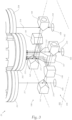
- Fig. 2 , Fig. 3 and Fig. 4 show schematically an exemplary embodiment of a light module 20 of a motor vehicle headlight, which includes eight light sources 211-218, each of which is set up to emit a collimated light beam 211-218.
- Fig. 3 and Fig. 4 is the light module 20 with the mirror device 100 Fig. 2 shown in perspective, with the representation of the Fig. 4 the arrangement 20 shows simplified.
- the notes on Fig. 1 with regard to the mirror device 100 apply equally.
- the light module 20 in turn comprises a mirror device 100 from the Fig. 1 , whereby the beam paths of the now eight light beams 211-218 with respective directions of incidence 251-258 are each guided onto a deflection mirror 111-118.
- the mirror device 100 serves to deflect and bundle eight incident, each collimated light beams 211-218 into a common main light beam bundle 102.
- Each of the incident light beams 211-218 enters the mirror device 100 along an assigned direction of incidence 251-258 normal to a main plane 101 of the mirror device 100.
- the main light beam bundle 102 in the direction of an extension direction 270 is aligned normal to the main plane 101 of the mirror device 100.
- the mirror device 100 has at least two mirrors for each incident light beam 211-218, which are arranged in the beam path of the respective light beam 211-218, namely a deflection mirror 111-118 and a central mirror 121-128.
- Each deflection mirror 111-118 has an orientation, position and shape that deflects the incident light beam 211-218 assigned to it from the respective direction of incidence to the central mirror 121-128 assigned to it.
- Each central mirror 121-128 has an orientation, position and shape that deflects the light beam 211-218 deflected onto it in the direction of the main light beam.
- the central mirrors 121-128 are positioned relative to one another in an arrangement in which the beam paths of the light beams 211-218 lie next to one another, preferably adjacent to one another, when viewed in the direction of the main light beam bundle. In special designs it can also be provided that the beam paths of the light beams overlap one another.
- the geometric distance between the deflection mirrors 111-118 of a pair of beam paths of the light beams 211-218 is greater than the distance between the central mirrors 121-128 of the pair of beam paths of the light beams 211-218.
- the four directions of incidence 251-254 and the direction of reflection 270 run in opposite directions to one another, as is the case with the directions of the beam paths of the light beams 111-118 at the respective locations on the deflection mirrors 111-118 or the central mirrors 121-128 by marking a circle with a central one point can be seen.
- the other four directions of incidence 255-258 of the beam paths of the light beams 115-118 lead from below into the plane of the drawing.
- the four directions of incidence 255-258 and the direction of departure 270 thus run in the same direction.
- the direction of incidence 270 of the eight beam paths of the light beams 111-118 runs upwards from the plane of the drawing.
- Two deflection mirrors 111 and 115, 112 and 116, 113 and 117, and 114 and 118 each form a common component 141-144.
- central mirrors 121, 122, 125 and 126 or 123, 124, 127 and 128 each form a common mirror surface and the eight central mirrors 121-128, which are formed on two mirror surfaces, form a total of a common component 147, as shown in the exemplary embodiment Mirror device 100 according to Fig. 5 is shown.
- the deflection mirrors 111-118 or the central mirrors 121-128 are inclined about respective deflection axes 151-158 or central axes 161-168, which axes are located in the main plane 101 or are oriented parallel to it.
- deflection axes 151-158 of the eight deflection mirrors 111-118 run coaxially, and the central axes 161-168 of the eight central mirrors 121-128 run coaxially.
- the deflection mirrors 111-118 and the central mirrors 121-128 are each inclined by ⁇ 45° with respect to the main plane 101 of the mirror device 1.
- a coupling mirror 131-138 is arranged in the beam path of the respective light beam 211-218 between the respective deflection mirror 111-118 and the respective central mirror 121-128.
- Two coupling mirrors 131 and 135, 132 and 136, 133 and 137, as well as 134 and 138 each form a common mirror surface and the coupling mirrors 131, 132, 135 and 136, as well as 133, 134, 137 and 138 each form a common component 145 and 146.
- the coupling mirrors 131-138 are each inclined about a coupling axis 171-178, which is oriented normal to the main plane 101.
- the coupling axes 171-178 of four coupling mirrors 131, 132, 135 and 136, or 133, 134, 137 and 138 run coaxially.
- the coupling mirrors 131-138 are inclined by ⁇ 45° with respect to the beam path of the light beams 211-218, or are oriented normal to the main plane 101 of the mirror device 1.
- a light conversion layer can be applied to at least one deflection mirror 111-118 and/or a central mirror 121-128 and/or a coupling mirror 131-138. This can be used if the incident light in one for one The spectral range is invisible to humans and is to be converted into a visible spectral range for use in a motor vehicle headlight.
- This light conversion layer can be arranged on the mirror surface of a deflection mirror 111-118 and/or a central mirror 121-128 and/or a coupling mirror 131-138, but is not shown in the figures.
- the Fig. 5 shows an exemplary embodiment of a mirror device 100 of a motor vehicle headlight.
- the mirror components 141-147 are connected to a common frame 103 or form a common component of the mirror device 100, the central mirror component 147 being connected to the frame 103 by means of a base plate 104.
- the base plate 104 has openings 105-108 to allow the incidence of collimated light beams 231-238 onto the associated mirror surfaces of the deflection mirrors 111-118.
- the exemplary embodiment of a mirror device 100 according to Fig. 2 to Fig. 5 shows an orientation of the deflection mirrors 111-118 of +45° or -45° each with respect to the main plane 101, that is to say the deflection axes 151-158 are parallel to the main plane 101.
- Component 141-144 Component 141-144.
- the central mirrors 121-128 have an orientation of +45° or -45° each with respect to the main plane 101, that is to say the central axes 161-168 are parallel to the main plane 101.
- Four central mirrors 121-128 each form a mirror surface.
- Two mirror surfaces of the central mirrors 121-128 each form a common central mirror component 147.
- the coupling mirrors 131-138 have an orientation of +45° or -45° each with respect to a normal to the main plane 101, that is to say the coupling axes 171-178 are normal to the main plane 101.
- Two coupling mirrors 131-138 each form a mirror surface.
- Two mirror surfaces of the coupling mirrors 131-138 each form a common coupling mirror component 145-146, 181-188.
- Fig. 6 shows schematically an embodiment not according to the invention for a light module 30 of a motor vehicle headlight, which comprises two light sources 201, 202, each of which is set up to emit a collimated light beam 211, 212.
- the light module 30 further comprises a mirror device 300, the beam paths of the two light beams 211, 212 each being guided onto a deflection mirror 311, 312 of the mirror device 300.
- the deflection mirrors 311, 312 form a common component 341 and the central mirrors 321, 322 form a common component 342.
- the arrangement has no coupling mirrors. The statements in the previous examples also apply.
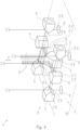
- Fig. 7 and Fig. 8 show schematically an exemplary embodiment of a light module 40 of a motor vehicle headlight, which comprises 16 light sources 201-218, 211-228, each of which is set up to emit a collimated light beam 211-218, 221-228.
- the light module 40 further comprises a mirror device 100, the beam paths of the 16 light beams 211-218, 221-228 each being guided onto a deflection mirror 111-118 of the mirror device 100.
- Two beam paths of the light beams 211-218, 231-238 are each guided to the same deflection mirror 111-118. This is achieved by arranging mirror components 181-188, which are used as coupling mirrors and deflect and focus two light beams from two different, preferably opposite directions.
- light beams 211 and 231 are deflected and focused by means of the mirrors on the mirror component 181. This ensures that two parallel beam paths of the light beams 211-218, 231-238 are each guided to a deflection mirror 111-118 of the mirror device 100.
- Fig. 8 the beam paths of the light beams 212, 214, 216, 218, 236 and 238 can be seen.
- the beam paths of the light beams 216 and 236 are bundled by a mirror component 186 and deflected in the direction of the deflection mirror component 142.
- the beam paths of the light beams 218 and 238 are bundled by a mirror component 188 and deflected in the direction of the deflection mirror component 144.
- the deflection mirror component 142 bundles the beam paths of the light beams 212, 216 and 236 and deflects them in the direction of the coupling mirror component 145.
- the deflection mirror component 144 bundles the beam paths of the light beams 214, 218 and 238 and deflects them in the direction of the coupling mirror component 146.
- the coupling mirror component 145 bundles the beam paths of the light beams 212, 216 and 236 and deflects them in the direction of the central mirror component 147.
- the coupling mirror component 146 bundles the beam paths of the light beams 214, 218 and 238 and deflects them in the direction of the central mirror component 147.
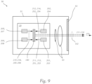
- Fig. 9 shows schematically a motor vehicle headlight 50 with a headlight housing 51 and a transparent headlight pane 52.
- the motor vehicle headlight 50 further includes the light module 20 according to Fig. 3 to Fig. 5 , which includes light sources 201-208 mounted on a common holder and the mirror device 100.
- the beam paths of the light beams 211-218 emitted by the light sources 201-208 in the direction of the direction of reflection 270 form the main light beam bundle 102 and can be further shaped by means of projection optics 53. Depending on the application, more may be possible optical elements, such as apertures or reflectors, are arranged in the respective beam path.
Landscapes
- Engineering & Computer Science (AREA)
- Physics & Mathematics (AREA)
- General Engineering & Computer Science (AREA)
- Optics & Photonics (AREA)
- General Physics & Mathematics (AREA)
- Condensed Matter Physics & Semiconductors (AREA)
- Electromagnetism (AREA)
- Microelectronics & Electronic Packaging (AREA)
- Non-Portable Lighting Devices Or Systems Thereof (AREA)
- Lighting Device Outwards From Vehicle And Optical Signal (AREA)
Priority Applications (3)
| Application Number | Priority Date | Filing Date | Title |
|---|---|---|---|
| EP18152029.7A EP3514447B1 (de) | 2018-01-17 | 2018-01-17 | Kraftfahrzeugscheinwerfer |
| KR1020190003359A KR102126259B1 (ko) | 2018-01-17 | 2019-01-10 | 자동차 헤드라이트 |
| CN201910043853.6A CN110043865B (zh) | 2018-01-17 | 2019-01-17 | 机动车前照灯 |
Applications Claiming Priority (1)
| Application Number | Priority Date | Filing Date | Title |
|---|---|---|---|
| EP18152029.7A EP3514447B1 (de) | 2018-01-17 | 2018-01-17 | Kraftfahrzeugscheinwerfer |
Publications (2)
| Publication Number | Publication Date |
|---|---|
| EP3514447A1 EP3514447A1 (de) | 2019-07-24 |
| EP3514447B1 true EP3514447B1 (de) | 2023-12-27 |
Family
ID=61005724
Family Applications (1)
| Application Number | Title | Priority Date | Filing Date |
|---|---|---|---|
| EP18152029.7A Active EP3514447B1 (de) | 2018-01-17 | 2018-01-17 | Kraftfahrzeugscheinwerfer |
Country Status (3)
| Country | Link |
|---|---|
| EP (1) | EP3514447B1 (ko) |
| KR (1) | KR102126259B1 (ko) |
| CN (1) | CN110043865B (ko) |
Families Citing this family (2)
| Publication number | Priority date | Publication date | Assignee | Title |
|---|---|---|---|---|
| JP6631798B2 (ja) * | 2016-06-30 | 2020-01-15 | ウシオ電機株式会社 | 投光装置 |
| CN117426031A (zh) * | 2021-06-14 | 2024-01-19 | 三菱电机株式会社 | 半导体激光装置以及半导体激光装置的制造方法 |
Family Cites Families (13)
| Publication number | Priority date | Publication date | Assignee | Title |
|---|---|---|---|---|
| CN100445801C (zh) * | 2006-01-18 | 2008-12-24 | 台达电子工业股份有限公司 | 用于光学设备的光线耦合装置 |
| JP5788194B2 (ja) * | 2011-03-03 | 2015-09-30 | シャープ株式会社 | 発光装置、照明装置、及び車両用前照灯 |
| DE102013200521B4 (de) * | 2013-01-15 | 2024-03-21 | Automotive Lighting Reutlingen Gmbh | Primäroptikeinrichtung für KFZ-Schweinwerfer mit Laserlichtquelle, schichtartigem Photolumineszenzelement, Lichtleitelement und Reflexionsflächen für Licht des Photolumineszenzelements und entsprechender KFZ-Scheinwerfer |
| JP2015069952A (ja) * | 2013-10-01 | 2015-04-13 | パナソニックIpマネジメント株式会社 | 車両用前照灯 |
| JPWO2015174312A1 (ja) * | 2014-05-15 | 2017-04-20 | 株式会社小糸製作所 | 光源モジュールおよび車両用灯具 |
| WO2015191659A1 (en) * | 2014-06-13 | 2015-12-17 | TeraDiode, Inc. | Optical alignment systems and methods for wavelength beam combining laser systems |
| FR3028007A1 (fr) * | 2014-10-29 | 2016-05-06 | Peugeot Citroen Automobiles Sa | Projecteur de vehicule |
| DE102015202961A1 (de) * | 2015-02-18 | 2016-08-18 | Osram Gmbh | Beleuchtungseinrichtung |
| US20170023200A1 (en) * | 2015-07-24 | 2017-01-26 | Ford Global Technologies, Llc | Headlamp assembly |
| DE102015218535A1 (de) * | 2015-09-28 | 2017-03-30 | Robert Bosch Gmbh | Lasermodul und Beleuchtungsvorrichtung mit einem Lasermodul |
| WO2018003409A1 (ja) * | 2016-06-30 | 2018-01-04 | ウシオ電機株式会社 | 投光装置 |
| JP2018006136A (ja) | 2016-06-30 | 2018-01-11 | ウシオ電機株式会社 | 投光装置 |
| JP6946054B2 (ja) | 2017-05-23 | 2021-10-06 | スタンレー電気株式会社 | 車両用灯具 |
-
2018
- 2018-01-17 EP EP18152029.7A patent/EP3514447B1/de active Active
-
2019
- 2019-01-10 KR KR1020190003359A patent/KR102126259B1/ko active IP Right Grant
- 2019-01-17 CN CN201910043853.6A patent/CN110043865B/zh active Active
Also Published As
| Publication number | Publication date |
|---|---|
| KR20190088012A (ko) | 2019-07-25 |
| EP3514447A1 (de) | 2019-07-24 |
| CN110043865B (zh) | 2022-03-29 |
| CN110043865A (zh) | 2019-07-23 |
| KR102126259B1 (ko) | 2020-06-25 |
Similar Documents
| Publication | Publication Date | Title |
|---|---|---|
| DE102012008833B4 (de) | Beleuchtungsanordnung und Fahrzeugscheinwerfer | |
| EP0562279A1 (de) | Beleuchtungseinrichtung für Fahrzeuge | |
| DE102014113700A1 (de) | Scheinwerfer für Fahrzeuge | |
| DE102016102263A1 (de) | Lichtgerät, insbesondere ein Scheinwerfer für Kraftfahrzeuge | |
| DE102015121697A1 (de) | Beleuchtungsvorrichtung für Fahrzeuge | |
| DE102015226633A1 (de) | Leuchtvorrichtung mit einem Halbleiterlaser und einer Linseneinrichtung | |
| EP3514447B1 (de) | Kraftfahrzeugscheinwerfer | |
| WO2016179620A1 (de) | Beleuchtungsvorrichtung mit einstellung der optischen bauelemente | |
| DE102020102226A1 (de) | Beleuchtungsvorrichtung für ein Fahrzeug, insbesondere Scheinwerfer | |
| DE102009008418A1 (de) | Beleuchtungsvorrichtung mit einer IR-LED-Lichtquelle | |
| DE10308703A1 (de) | Kraftfahrzeugscheinwerfer | |
| DE10016882A1 (de) | Beleuchtungseinrichtung und Verfahren zum Betreiben einer Beleuchtungseinrichtung | |
| DE10109047A1 (de) | Beleuchtungs- und Signalvorrichtungen für Fahr- oder Flugzeuge | |
| WO2021239590A1 (de) | Kraftfahrzeug | |
| DE102013221953A1 (de) | Leuchtvorrichtung für ein Kraftfahrzeug | |
| WO2018114558A1 (de) | System, verfahren, computerprogrammprodukt und computerlesbares medium zur lichtformung für eine fahrzeugaussenleuchte | |
| DE102011000699A1 (de) | Beleuchtungsvorrichtung für Fahrzeuge | |
| DE102017118139A1 (de) | Beleuchtungsvorrichtung für Fahrzeuge | |
| EP3686480B1 (de) | Anordnung zur lichtabgabe mit veränderbarer lichtabstrahlcharakteristik | |
| DE10308704A1 (de) | Kraftfahrzeugscheinwerfer | |
| DE10143357B4 (de) | Starrer Lichtleiter | |
| DE102015218535A1 (de) | Lasermodul und Beleuchtungsvorrichtung mit einem Lasermodul | |
| DE102017127355B4 (de) | Leuchte für eine Kraftfahrzeugkarosserie | |
| DE202004009121U1 (de) | Scheinwerfer mit änderbarem Projektionsbild | |
| DE102012100139B4 (de) | Lichtmodul für einen Scheinwerfer eines Fahrzeugs mit einer Laserstrahlquelle |
Legal Events
| Date | Code | Title | Description |
|---|---|---|---|
| PUAI | Public reference made under article 153(3) epc to a published international application that has entered the european phase |
Free format text: ORIGINAL CODE: 0009012 |
|
| STAA | Information on the status of an ep patent application or granted ep patent |
Free format text: STATUS: THE APPLICATION HAS BEEN PUBLISHED |
|
| AK | Designated contracting states |
Kind code of ref document: A1 Designated state(s): AL AT BE BG CH CY CZ DE DK EE ES FI FR GB GR HR HU IE IS IT LI LT LU LV MC MK MT NL NO PL PT RO RS SE SI SK SM TR |
|
| AX | Request for extension of the european patent |
Extension state: BA ME |
|
| STAA | Information on the status of an ep patent application or granted ep patent |
Free format text: STATUS: REQUEST FOR EXAMINATION WAS MADE |
|
| 17P | Request for examination filed |
Effective date: 20200123 |
|
| RBV | Designated contracting states (corrected) |
Designated state(s): AL AT BE BG CH CY CZ DE DK EE ES FI FR GB GR HR HU IE IS IT LI LT LU LV MC MK MT NL NO PL PT RO RS SE SI SK SM TR |
|
| STAA | Information on the status of an ep patent application or granted ep patent |
Free format text: STATUS: EXAMINATION IS IN PROGRESS |
|
| 17Q | First examination report despatched |
Effective date: 20220301 |
|
| RIC1 | Information provided on ipc code assigned before grant |
Ipc: G02B 27/14 20060101ALI20230829BHEP Ipc: G02B 27/10 20060101ALI20230829BHEP Ipc: H01S 5/40 20060101ALI20230829BHEP Ipc: H01S 5/00 20060101ALI20230829BHEP Ipc: F21S 41/365 20180101ALI20230829BHEP Ipc: F21S 41/176 20180101ALI20230829BHEP Ipc: F21S 41/16 20180101AFI20230829BHEP |
|
| GRAP | Despatch of communication of intention to grant a patent |
Free format text: ORIGINAL CODE: EPIDOSNIGR1 |
|
| STAA | Information on the status of an ep patent application or granted ep patent |
Free format text: STATUS: GRANT OF PATENT IS INTENDED |
|
| GRAS | Grant fee paid |
Free format text: ORIGINAL CODE: EPIDOSNIGR3 |
|
| INTG | Intention to grant announced |
Effective date: 20231023 |
|
| GRAA | (expected) grant |
Free format text: ORIGINAL CODE: 0009210 |
|
| STAA | Information on the status of an ep patent application or granted ep patent |
Free format text: STATUS: THE PATENT HAS BEEN GRANTED |
|
| AK | Designated contracting states |
Kind code of ref document: B1 Designated state(s): AL AT BE BG CH CY CZ DE DK EE ES FI FR GB GR HR HU IE IS IT LI LT LU LV MC MK MT NL NO PL PT RO RS SE SI SK SM TR |
|
| REG | Reference to a national code |
Ref country code: GB Ref legal event code: FG4D Free format text: NOT ENGLISH |
|
| REG | Reference to a national code |
Ref country code: CH Ref legal event code: EP |
|
| REG | Reference to a national code |
Ref country code: DE Ref legal event code: R096 Ref document number: 502018013855 Country of ref document: DE |
|
| REG | Reference to a national code |
Ref country code: IE Ref legal event code: FG4D Free format text: LANGUAGE OF EP DOCUMENT: GERMAN |
|
| PGFP | Annual fee paid to national office [announced via postgrant information from national office to epo] |
Ref country code: FR Payment date: 20231222 Year of fee payment: 7 |
|
| PG25 | Lapsed in a contracting state [announced via postgrant information from national office to epo] |
Ref country code: GR Free format text: LAPSE BECAUSE OF FAILURE TO SUBMIT A TRANSLATION OF THE DESCRIPTION OR TO PAY THE FEE WITHIN THE PRESCRIBED TIME-LIMIT Effective date: 20240328 |
|
| REG | Reference to a national code |
Ref country code: LT Ref legal event code: MG9D |
|
| PG25 | Lapsed in a contracting state [announced via postgrant information from national office to epo] |
Ref country code: LT Free format text: LAPSE BECAUSE OF FAILURE TO SUBMIT A TRANSLATION OF THE DESCRIPTION OR TO PAY THE FEE WITHIN THE PRESCRIBED TIME-LIMIT Effective date: 20231227 |
|
| PG25 | Lapsed in a contracting state [announced via postgrant information from national office to epo] |
Ref country code: ES Free format text: LAPSE BECAUSE OF FAILURE TO SUBMIT A TRANSLATION OF THE DESCRIPTION OR TO PAY THE FEE WITHIN THE PRESCRIBED TIME-LIMIT Effective date: 20231227 |
|
| PG25 | Lapsed in a contracting state [announced via postgrant information from national office to epo] |
Ref country code: LT Free format text: LAPSE BECAUSE OF FAILURE TO SUBMIT A TRANSLATION OF THE DESCRIPTION OR TO PAY THE FEE WITHIN THE PRESCRIBED TIME-LIMIT Effective date: 20231227 Ref country code: GR Free format text: LAPSE BECAUSE OF FAILURE TO SUBMIT A TRANSLATION OF THE DESCRIPTION OR TO PAY THE FEE WITHIN THE PRESCRIBED TIME-LIMIT Effective date: 20240328 Ref country code: FI Free format text: LAPSE BECAUSE OF FAILURE TO SUBMIT A TRANSLATION OF THE DESCRIPTION OR TO PAY THE FEE WITHIN THE PRESCRIBED TIME-LIMIT Effective date: 20231227 Ref country code: ES Free format text: LAPSE BECAUSE OF FAILURE TO SUBMIT A TRANSLATION OF THE DESCRIPTION OR TO PAY THE FEE WITHIN THE PRESCRIBED TIME-LIMIT Effective date: 20231227 Ref country code: BG Free format text: LAPSE BECAUSE OF FAILURE TO SUBMIT A TRANSLATION OF THE DESCRIPTION OR TO PAY THE FEE WITHIN THE PRESCRIBED TIME-LIMIT Effective date: 20240327 |
|
| PGFP | Annual fee paid to national office [announced via postgrant information from national office to epo] |
Ref country code: DE Payment date: 20231219 Year of fee payment: 7 |
|
| REG | Reference to a national code |
Ref country code: NL Ref legal event code: MP Effective date: 20231227 |
|
| P01 | Opt-out of the competence of the unified patent court (upc) registered |
Effective date: 20240408 |
|
| PG25 | Lapsed in a contracting state [announced via postgrant information from national office to epo] |
Ref country code: NL Free format text: LAPSE BECAUSE OF FAILURE TO SUBMIT A TRANSLATION OF THE DESCRIPTION OR TO PAY THE FEE WITHIN THE PRESCRIBED TIME-LIMIT Effective date: 20231227 |