EP3514395A1 - Rivet fileté aveugle - Google Patents
Rivet fileté aveugle Download PDFInfo
- Publication number
- EP3514395A1 EP3514395A1 EP18152534.6A EP18152534A EP3514395A1 EP 3514395 A1 EP3514395 A1 EP 3514395A1 EP 18152534 A EP18152534 A EP 18152534A EP 3514395 A1 EP3514395 A1 EP 3514395A1
- Authority
- EP
- European Patent Office
- Prior art keywords
- blind rivet
- bolt
- rivet
- sleeve
- rivet screw
- Prior art date
- Legal status (The legal status is an assumption and is not a legal conclusion. Google has not performed a legal analysis and makes no representation as to the accuracy of the status listed.)
- Pending
Links
- 239000000463 material Substances 0.000 claims description 28
- 238000000605 extraction Methods 0.000 claims description 4
- 230000000052 comparative effect Effects 0.000 claims description 3
- 230000015572 biosynthetic process Effects 0.000 description 2
- 150000001875 compounds Chemical class 0.000 description 1
- 238000002788 crimping Methods 0.000 description 1
- 239000002184 metal Substances 0.000 description 1
- 230000008092 positive effect Effects 0.000 description 1
- 230000003313 weakening effect Effects 0.000 description 1
Images

Classifications
-
- F—MECHANICAL ENGINEERING; LIGHTING; HEATING; WEAPONS; BLASTING
- F16—ENGINEERING ELEMENTS AND UNITS; GENERAL MEASURES FOR PRODUCING AND MAINTAINING EFFECTIVE FUNCTIONING OF MACHINES OR INSTALLATIONS; THERMAL INSULATION IN GENERAL
- F16B—DEVICES FOR FASTENING OR SECURING CONSTRUCTIONAL ELEMENTS OR MACHINE PARTS TOGETHER, e.g. NAILS, BOLTS, CIRCLIPS, CLAMPS, CLIPS OR WEDGES; JOINTS OR JOINTING
- F16B37/00—Nuts or like thread-engaging members
- F16B37/04—Devices for fastening nuts to surfaces, e.g. sheets, plates
- F16B37/06—Devices for fastening nuts to surfaces, e.g. sheets, plates by means of welding or riveting
- F16B37/062—Devices for fastening nuts to surfaces, e.g. sheets, plates by means of welding or riveting by means of riveting
- F16B37/065—Devices for fastening nuts to surfaces, e.g. sheets, plates by means of welding or riveting by means of riveting by deforming the material of the nut
- F16B37/067—Devices for fastening nuts to surfaces, e.g. sheets, plates by means of welding or riveting by means of riveting by deforming the material of the nut the material of the nut being deformed by a threaded member generating axial movement of the threaded part of the nut, e.g. blind rivet type
Definitions
- the present invention relates to a blind rivet with a rivet sleeve, which has a setting head and a deformation region for forming a closing head, and a bolt with an external thread which protrudes with a threaded portion of the setting head and is connected in a connecting region with the rivet.
- Such a blind rivet screw is fastened in the manner of a blind rivet in a structure which is referred to below as "joining material".
- the structure may be a single plate or a sheet. It but can also be a stack of two or more plate-like objects.
- the bolt with the external thread is available in order to fasten further parts to the joint material.
- a blind rivet screw in a motor vehicle to connect an airbag unit to the body of the motor vehicle.
- a preferred field of application of such a blind rivet screw is vehicle technology, which includes not only passenger cars but also trucks, railway carriages and airplanes.
- vehicle technology includes not only passenger cars but also trucks, railway carriages and airplanes.
- the weight or mass of the parts used plays a relatively large role, because during the movement of such a vehicle, this mass must be accelerated and decelerated.
- the invention has for its object to provide a blind rivet with small mass.
- the mass of the blind rivet screw can be kept to a minimum.
- the threaded portion protruding from the setting head only has a maximum of four threads plus 1 mm. Only this length is thus available for screwing a nut or the like. But this length is sufficient because with a screw connection between an internal thread and a External thread anyway the main load of the threaded connection of three threads is worn.
- the threaded portion only protrudes from the rivet sleeve by a maximum of four threads plus 1 mm plus the thickness of the set target area, then it may be that in the undeformed condition of the rivet sleeve the length of the threaded portion protruding from the rivet sleeve is too short to engage a tool that generates the closing head by applying a pulling force.
- the threaded section with at least four threads of the rivet sleeve before may arise, for example, if the thickness of the material to be joined is substantially greater than the thickness of the Anschraubguts.
- the thickness of the Anschraubguts which is to be fixed with the Blindnietschraube to the joining material, determines the target mounting area.
- the length of the threaded portion is thus defined to at least 4 threads with undeformed rivet and, if it could be longer with deformed rivet with trained lock then longer, to a maximum of 4 threads plus 1 mm plus target mounting area.
- the threaded portion is formed with a trained closing head a maximum of four threads longer than the Anschraubgut-desired range. This saves the 1 mm longer training of the embodiment described above. Again, however, that the threaded portion protrudes at undeformed rivet at least four threads on the rivet.
- connection area has at least one hole.
- the connection area between the bolt and the rivet sleeve is practically only loaded with tension on a blind rivet screw. If you remove material here, you can achieve a further saving in the mass of the blind rivet screw.
- the connecting region has at its end facing away from the setting head a radially inwardly facing bolt abutment wall, wherein the bolt abutment wall is preferably closed and in particular has a contour which deviates from a plane.
- the bolt is screwed into the rivet sleeve, more precisely into the connecting area of the rivet sleeve, namely until it comes into contact with the bolt abutment wall. If a sufficient torque is applied during this screwing, results in a jamming between the bolt and the connecting portion, which is usually sufficient to hold the bolt reliably in the rivet.
- it has been found that most of the contact force is absorbed by an area of the bolt abutment wall which lies radially outward.
- the bolt abutment wall may be limited to making the bolt abutment wall thick, while radially further inside, it may have a reduced thickness.
- the reduction in thickness of the bolt system wall can be ramped. In extreme cases, you can also provide a hole in the radial center of the bolt system wall to save mass.
- connection area has a thread with a maximum of two threads.
- Such a connection is sufficient to achieve the desired bracing forces.
- the connection area in the axial direction (relative to the axis of the bolt) is relatively short, so that one can also save material and thus mass here.
- the bolt has a thread-free holding contour in the connection region.
- This holding contour can for example consist of an axially extending toothing.
- the bolt and the rivet sleeve are integrally formed.
- the setting head and / or the deformed to the closing head deformation region has a comparison strength that is greater than a thread extraction force of the external thread, the comparison strength is in particular at most 50% higher, in particular at most 25% higher than the thread extraction force.
- the setting head and the deformation region can then be made relatively thin, which has a positive effect in a small mass.
- the rivet sleeve at least in the region of the setting head and / or deformation region, comprises a material in which the ratio between the elastic limit and the elongation at break is at least 10%, preferably at least 12%.
- the elastic limit also referred to as 0.2 percent proof stress or abbreviated R p, 0.2 , is the stress at which the residual elongation after relieving the initial length of the specimen is 0.2%.
- the rivet sleeve preferably has at least two different wall thicknesses between the setting head and the connecting region. You can use a thinner wall thickness to reduce the mass of the blind rivet screw.
- the rivet sleeve adjacent to the setting head has a smaller wall thickness than adjacent to the connection region.
- An area adjacent to the setting head is at least partially inserted into the material to be joined when setting the blind rivet screw and is then stabilized radially outward by the material to be joined. In this case, one can use a relatively small wall thickness without weakening the ability of the blind rivet screw to carry a given load.
- At least a portion of the rivet sleeve on its inner and / or outer periphery has a shape which deviates from a cylindrical or conical shape.
- a deviation can be formed, for example, in that the shape of the circumference is formed by a polygon, a helical shape or ribs. It is also possible to use here radially outwardly facing webs.
- the strength of the joint portion is strengthened in a radial direction, so that, with sufficient strength, it is necessary to use little material for the joint portion.
- the bolt has a cavity. This also saves material and thus mass.
- the load-carrying properties of the bolt are not affected by a cavity practically or at least not significantly negatively.
- the invention also relates to a fastening arrangement with a blind rivet screw, as described above, and a nut with an internal thread, in which the internal thread has a maximum of four threads.
- the nut With a maximum of four threads, the nut can be kept very short in the axial direction. This in turn saves material and thus mass. With four threads a sufficient fastening force is given.
- the internal thread has a first increase and the external thread has a second increase, wherein the first increase and the second increase differ by at least 2%.
- This is indeed a screwing the nut on the threaded portion possible. But it results in a distortion of the internal thread on the external thread, so that the load-carrying properties of the individual threads are slightly more closely matched to each other than in a threaded pairing, in which the two slopes are the same.
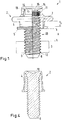
- Fig.1 shows a fastening assembly 1 with a blind rivet 2 and a nut. 3
- the blind rivet screw 2 has a rivet sleeve 4 with a setting head 5 and a deformation region 6 (FIG. Fig. 2 ) for forming a closing head 7 (FIG. Fig. 1 ) on.
- the blind rivet screw 2 also has bolts 8 with an external thread 9, which protrudes with a threaded portion 10 from the setting head 5 and is connected in a connecting region 11 with the rivet sleeve 4.
- Such a blind rivet screw 2 is usually provided for a precisely specified purpose.
- Fig. 1 Therefore, two parameters are shown, which are essential for the respective blind rivet 2.
- the length of the rivet sleeve 4 is matched to the joint material thickness F in order to ensure the correct formation of the closing head 7.
- the joining material may be, for example, a metal sheet or another sheet-like element. It may also be a stack of two or more such elements, which are also connected to each other when setting the blind rivet screw 2.
- Anschraubgutdicke ie the thickness of a Guts, which is to be fastened by means of the blind rivet 2 to the Fügegut.
- the Anschraubdicke thus forms a Anschraubgut-desired area A.
- the tightening target area A then defines the maximum allowable thickness of the intended Anschraubguts.
- the blind rivet screw is dimensioned such that the bolt 8 in the set state of the blind rivet screw 2, that is to say after formation of the closing head 7, protrudes with its threaded portion 10 as far as possible out of the rivet sleeve 4 on the side of the setting head 5, that the external thread after placement of the Anschraubguts protrudes with a maximum of four complete threads on the Anschraubgut.
- a surcharge of 1 mm may be allowed.
- conical tip of the bolt 8, which is thread-free remains outside in this consideration.
- the threaded portion that is, the part of the external thread 9 protruding from the rivet sleeve 4 has a maximum of four threads plus 1 mm longer than the target area A to be screwed on.
- the nut 3 has an internal thread 12 and a maximum of 4 threads.
- the internal thread 12 has a pitch which differs from the pitch of the external thread 9. The difference is at least 2%, but no more than 5%. This makes it possible to unscrew the nut 3 on the bolt 8, even if this requires an increased moment.
- the two threads 9, 12 brace something against each other, so that the loads are distributed more uniformly on the individual threads.
- the bolt 8 When forming the closing head 7, the bolt 8 is pulled out of the rivet sleeve slightly. In unfavorable conditions between the Anschraubgut-desired range A and Fügegutdicke F, it may then happen that with the above dimensioning rule of the threaded portion 10 when setting the blind rivet, so in undeformed state of the rivet 4 is too short to attack with a tool on the external thread 9 of the bolt 8 in order to apply the required to form the closing head 7 traction.
- the bolt 8 is, as in various embodiments of Fig. 3 can be seen formed with a cavity 13.
- the cavity can either be from a front side ( Fig. 3a ) or from the opposite end face ( Fig. 3b ) go out or he can enforce the bolt 8 over its entire length. This also saves mass.
- the bolt 8 has a head 14, which abuts against the rivet sleeve from the side facing away from the setting head 5.
- the bolt 8 has in the attachment area a thread-free retaining contour 15 in the form of a corrugation on which the rivet sleeve 4 is stamped in the connection area 11.
- the rivet sleeve 4 has at least one opening 16 in the connection region. This also saves material.
- Fig. 2 is one opposite Fig. 1 shown modified embodiment in which the bolt 8 is screwed in the connecting portion 11 in the rivet 4.
- the bolt 8 then abuts against a bolt abutment wall 17.
- the bolt abutment wall may simply be a radially inwardly projecting one Be projection of the rivet 4. However, it may also, as shown, be formed as a closed wall and have a contour which deviates from a plane. In the present case, the bolt system wall 17 has a conical depression 18, in which material is again saved.
- connection between the pin 8 and the sleeve 4 is formed in the connection area by a screw, which has a maximum of two threads.
- the bolt 8 is screwed into the connecting region 11 as far as the stop on the bolt system wall 17 and then clamped by applying a slightly larger torque against the bolt system wall 17.
- Such a compound, optionally including a subsequent crimping is sufficient to prevent accidental release.
- a torque on the bolt 8 is applied when screwing the nut 3, which would screw the bolt 8 further into the sleeve 4, so that even in this case accidental release is not to be feared.
- the rivet sleeve 4 on two different wall thicknesses.
- the rivet sleeve 4 has adjacent to the setting head 5 has a smaller wall thickness than adjacent to the connecting portion 11. Shown are two discrete wall thicknesses. But it is also possible that the thickness of the wall of the rivet sleeve 4 tapers continuously or according to another function in the connection region 11 to the setting head 5 out.
- the rivet sleeve 4 has a shape on the outer circumference, which deviates from a cylindrical or a cone shape.
- the rivet 4 has here a number of radially outwardly projecting ribs 19 which reinforce the connecting portion 11, without a corresponding material thickness over the entire circumference would be necessary.
- the same embodiment is also found in the embodiment Fig. 1 ,
- the rivet sleeve 4, but at least the setting head 7 and / or the deformation region 6 are formed from a material or comprise a material in which the ratio between the elastic limit and elongation at break is at least 10%, preferably at least 12%.
- This material thus forms a higher-strength material that can be heavily loaded.
- material can be saved by making the setting head 5 or the wall of the deformation section 6 relatively thin. This results in a total of a blind rivet 2 with a low mass.
- the setting head 5 and / or the deformation zone 6 deformed to the closing head 7 have a comparative strength which is greater than a thread withdrawal force of the external thread 9.
- This comparison strength should preferably be at most 50% higher, in particular at most 25% higher than be the thread extraction force.
- This material can be saved in turn, because the setting head 5 and / or the deformation region 6, which is to be formed to the closing head 7, may be formed relatively massearm.
- the blind rivet screw 2 has the following tasks: It is intended to hold together two or more elements of a material to be joined. It should also provide an external thread 9 available to screw later further elements here. The comparative strength and the thread pull-out force are now matched to one another such that if the thread fails, at least the first task, namely joining, is still maintained.
- Fig. 4 shows a further modified embodiment of a blind rivet screw 2, in which the bolt 8 and the rivet sleeve 4 are integrally formed. in the The rest are in the FIGS. 1 to 3 described features.
- the bolt 8 can also, as in Fig. 3 shown to be provided with a cavity 13.
Priority Applications (1)
| Application Number | Priority Date | Filing Date | Title |
|---|---|---|---|
| EP18152534.6A EP3514395A1 (fr) | 2018-01-19 | 2018-01-19 | Rivet fileté aveugle |
Applications Claiming Priority (1)
| Application Number | Priority Date | Filing Date | Title |
|---|---|---|---|
| EP18152534.6A EP3514395A1 (fr) | 2018-01-19 | 2018-01-19 | Rivet fileté aveugle |
Publications (1)
| Publication Number | Publication Date |
|---|---|
| EP3514395A1 true EP3514395A1 (fr) | 2019-07-24 |
Family
ID=61017820
Family Applications (1)
| Application Number | Title | Priority Date | Filing Date |
|---|---|---|---|
| EP18152534.6A Pending EP3514395A1 (fr) | 2018-01-19 | 2018-01-19 | Rivet fileté aveugle |
Country Status (1)
| Country | Link |
|---|---|
| EP (1) | EP3514395A1 (fr) |
Citations (5)
| Publication number | Priority date | Publication date | Assignee | Title |
|---|---|---|---|---|
| DE10001301A1 (de) * | 2000-01-14 | 2001-07-19 | Opel Adam Ag | Gewindemutter |
| DE10126747A1 (de) * | 2001-05-31 | 2002-12-19 | Gesipa Blindniettechnik | Blindnietmutter und Befestigungseinheit |
| EP1918596A1 (fr) * | 2006-11-03 | 2008-05-07 | Herbert Schruff | Rivet aveugle et son utilisation |
| EP2594813A1 (fr) * | 2011-11-21 | 2013-05-22 | Dregischan, Simone | Elément de rivet aveugle |
| EP2910801A1 (fr) * | 2014-02-24 | 2015-08-26 | GESIPA Blindniettechnik GmbH | Système de fixation à rivet aveugle |
-
2018
- 2018-01-19 EP EP18152534.6A patent/EP3514395A1/fr active Pending
Patent Citations (5)
| Publication number | Priority date | Publication date | Assignee | Title |
|---|---|---|---|---|
| DE10001301A1 (de) * | 2000-01-14 | 2001-07-19 | Opel Adam Ag | Gewindemutter |
| DE10126747A1 (de) * | 2001-05-31 | 2002-12-19 | Gesipa Blindniettechnik | Blindnietmutter und Befestigungseinheit |
| EP1918596A1 (fr) * | 2006-11-03 | 2008-05-07 | Herbert Schruff | Rivet aveugle et son utilisation |
| EP2594813A1 (fr) * | 2011-11-21 | 2013-05-22 | Dregischan, Simone | Elément de rivet aveugle |
| EP2910801A1 (fr) * | 2014-02-24 | 2015-08-26 | GESIPA Blindniettechnik GmbH | Système de fixation à rivet aveugle |
Similar Documents
| Publication | Publication Date | Title |
|---|---|---|
| EP1918596B1 (fr) | Rivet aveugle et son utilisation | |
| DE19749219B4 (de) | Nicht-wiederabnehmbare Befestigungsvorrichtung | |
| EP3698055A1 (fr) | Ensemble de compensation de tolérances | |
| EP1961976B1 (fr) | Dispositif de fixation | |
| EP3565976B1 (fr) | Dispositif de limitation de couple comportant trois brides | |
| EP3565978B1 (fr) | Limiteur de couple comprenant une pince | |
| DE102012221228A1 (de) | Toleranzausgleichsvorrichtung | |
| EP3315799B1 (fr) | Ecrou à rivet aveugle | |
| EP3387270B1 (fr) | Élément de fixation | |
| WO2020200776A1 (fr) | Élément de réglage en plusieurs parties pour un agencement de compensation de tolérances | |
| DE102009024264A1 (de) | Befestigungselement, insbesondere Mutter | |
| WO2007134654A1 (fr) | Système de vis et rivet aveugle, ensemble de liaison à vis et rivet aveugle, et procédé pour relier deux composants avec le système de vis et rivet aveugle | |
| EP2910801B1 (fr) | Système de fixation à rivet aveugle | |
| DE102014207554B4 (de) | Kraftfahrzeug mit einer Verbindungshülsen-Verbindungsanordnung | |
| EP2627915A1 (fr) | Dispositif d'ancrage destiné à fixer une pièce sur un élément de support | |
| EP3514395A1 (fr) | Rivet fileté aveugle | |
| EP0457249B1 (fr) | Attelage de remorque mot clef: dispositif antiperte avec distance de sécurité | |
| DE2641909A1 (de) | Blindbefestiger mit mehreren muffen | |
| DE102012220033A1 (de) | Funktionselement zum Einpressen in ein Blechteil und Zusammenbauteil bestehend aus dem Funktionselement und einem Blechteil | |
| DE19734539C2 (de) | Bauteilverbindung | |
| WO2001038747A1 (fr) | Ecrou dote d'une rondelle | |
| DE102004018800A1 (de) | Montageeinheit mit einer Nietverbindung | |
| DE102010055808A1 (de) | Befestigungsvorrichtung | |
| DE2619728A1 (de) | Blindbefestiger mit mehreren muffen | |
| DE202021100435U1 (de) | Rahmenbefestigungsanordnung, Tür und Befestigungsmittel |
Legal Events
| Date | Code | Title | Description |
|---|---|---|---|
| PUAI | Public reference made under article 153(3) epc to a published international application that has entered the european phase |
Free format text: ORIGINAL CODE: 0009012 |
|
| STAA | Information on the status of an ep patent application or granted ep patent |
Free format text: STATUS: THE APPLICATION HAS BEEN PUBLISHED |
|
| AK | Designated contracting states |
Kind code of ref document: A1 Designated state(s): AL AT BE BG CH CY CZ DE DK EE ES FI FR GB GR HR HU IE IS IT LI LT LU LV MC MK MT NL NO PL PT RO RS SE SI SK SM TR |
|
| AX | Request for extension of the european patent |
Extension state: BA ME |
|
| STAA | Information on the status of an ep patent application or granted ep patent |
Free format text: STATUS: REQUEST FOR EXAMINATION WAS MADE |
|
| 17P | Request for examination filed |
Effective date: 20191203 |
|
| RBV | Designated contracting states (corrected) |
Designated state(s): AL AT BE BG CH CY CZ DE DK EE ES FI FR GB GR HR HU IE IS IT LI LT LU LV MC MK MT NL NO PL PT RO RS SE SI SK SM TR |
|
| STAA | Information on the status of an ep patent application or granted ep patent |
Free format text: STATUS: EXAMINATION IS IN PROGRESS |
|
| STAA | Information on the status of an ep patent application or granted ep patent |
Free format text: STATUS: EXAMINATION IS IN PROGRESS |
|
| 17Q | First examination report despatched |
Effective date: 20201214 |
|
| STAA | Information on the status of an ep patent application or granted ep patent |
Free format text: STATUS: EXAMINATION IS IN PROGRESS |
|
| RAP1 | Party data changed (applicant data changed or rights of an application transferred) |
Owner name: SFS GROUP GERMANY GMBH |
|
| GRAP | Despatch of communication of intention to grant a patent |
Free format text: ORIGINAL CODE: EPIDOSNIGR1 |
|
| STAA | Information on the status of an ep patent application or granted ep patent |
Free format text: STATUS: GRANT OF PATENT IS INTENDED |
|
| INTG | Intention to grant announced |
Effective date: 20240305 |