EP3514395A1 - Blind rivet screw - Google Patents
Blind rivet screw Download PDFInfo
- Publication number
- EP3514395A1 EP3514395A1 EP18152534.6A EP18152534A EP3514395A1 EP 3514395 A1 EP3514395 A1 EP 3514395A1 EP 18152534 A EP18152534 A EP 18152534A EP 3514395 A1 EP3514395 A1 EP 3514395A1
- Authority
- EP
- European Patent Office
- Prior art keywords
- blind rivet
- bolt
- rivet
- sleeve
- rivet screw
- Prior art date
- Legal status (The legal status is an assumption and is not a legal conclusion. Google has not performed a legal analysis and makes no representation as to the accuracy of the status listed.)
- Pending
Links
- 239000000463 material Substances 0.000 claims description 28
- 238000000605 extraction Methods 0.000 claims description 4
- 230000000052 comparative effect Effects 0.000 claims description 3
- 230000015572 biosynthetic process Effects 0.000 description 2
- 150000001875 compounds Chemical class 0.000 description 1
- 238000002788 crimping Methods 0.000 description 1
- 239000002184 metal Substances 0.000 description 1
- 230000008092 positive effect Effects 0.000 description 1
- 230000003313 weakening effect Effects 0.000 description 1
Images

Classifications
-
- F—MECHANICAL ENGINEERING; LIGHTING; HEATING; WEAPONS; BLASTING
- F16—ENGINEERING ELEMENTS AND UNITS; GENERAL MEASURES FOR PRODUCING AND MAINTAINING EFFECTIVE FUNCTIONING OF MACHINES OR INSTALLATIONS; THERMAL INSULATION IN GENERAL
- F16B—DEVICES FOR FASTENING OR SECURING CONSTRUCTIONAL ELEMENTS OR MACHINE PARTS TOGETHER, e.g. NAILS, BOLTS, CIRCLIPS, CLAMPS, CLIPS OR WEDGES; JOINTS OR JOINTING
- F16B37/00—Nuts or like thread-engaging members
- F16B37/04—Devices for fastening nuts to surfaces, e.g. sheets, plates
- F16B37/06—Devices for fastening nuts to surfaces, e.g. sheets, plates by means of welding or riveting
- F16B37/062—Devices for fastening nuts to surfaces, e.g. sheets, plates by means of welding or riveting by means of riveting
- F16B37/065—Devices for fastening nuts to surfaces, e.g. sheets, plates by means of welding or riveting by means of riveting by deforming the material of the nut
- F16B37/067—Devices for fastening nuts to surfaces, e.g. sheets, plates by means of welding or riveting by means of riveting by deforming the material of the nut the material of the nut being deformed by a threaded member generating axial movement of the threaded part of the nut, e.g. blind rivet type
Definitions
- the present invention relates to a blind rivet with a rivet sleeve, which has a setting head and a deformation region for forming a closing head, and a bolt with an external thread which protrudes with a threaded portion of the setting head and is connected in a connecting region with the rivet.
- Such a blind rivet screw is fastened in the manner of a blind rivet in a structure which is referred to below as "joining material".
- the structure may be a single plate or a sheet. It but can also be a stack of two or more plate-like objects.
- the bolt with the external thread is available in order to fasten further parts to the joint material.
- a blind rivet screw in a motor vehicle to connect an airbag unit to the body of the motor vehicle.
- a preferred field of application of such a blind rivet screw is vehicle technology, which includes not only passenger cars but also trucks, railway carriages and airplanes.
- vehicle technology includes not only passenger cars but also trucks, railway carriages and airplanes.
- the weight or mass of the parts used plays a relatively large role, because during the movement of such a vehicle, this mass must be accelerated and decelerated.
- the invention has for its object to provide a blind rivet with small mass.
- the mass of the blind rivet screw can be kept to a minimum.
- the threaded portion protruding from the setting head only has a maximum of four threads plus 1 mm. Only this length is thus available for screwing a nut or the like. But this length is sufficient because with a screw connection between an internal thread and a External thread anyway the main load of the threaded connection of three threads is worn.
- the threaded portion only protrudes from the rivet sleeve by a maximum of four threads plus 1 mm plus the thickness of the set target area, then it may be that in the undeformed condition of the rivet sleeve the length of the threaded portion protruding from the rivet sleeve is too short to engage a tool that generates the closing head by applying a pulling force.
- the threaded section with at least four threads of the rivet sleeve before may arise, for example, if the thickness of the material to be joined is substantially greater than the thickness of the Anschraubguts.
- the thickness of the Anschraubguts which is to be fixed with the Blindnietschraube to the joining material, determines the target mounting area.
- the length of the threaded portion is thus defined to at least 4 threads with undeformed rivet and, if it could be longer with deformed rivet with trained lock then longer, to a maximum of 4 threads plus 1 mm plus target mounting area.
- the threaded portion is formed with a trained closing head a maximum of four threads longer than the Anschraubgut-desired range. This saves the 1 mm longer training of the embodiment described above. Again, however, that the threaded portion protrudes at undeformed rivet at least four threads on the rivet.
- connection area has at least one hole.
- the connection area between the bolt and the rivet sleeve is practically only loaded with tension on a blind rivet screw. If you remove material here, you can achieve a further saving in the mass of the blind rivet screw.
- the connecting region has at its end facing away from the setting head a radially inwardly facing bolt abutment wall, wherein the bolt abutment wall is preferably closed and in particular has a contour which deviates from a plane.
- the bolt is screwed into the rivet sleeve, more precisely into the connecting area of the rivet sleeve, namely until it comes into contact with the bolt abutment wall. If a sufficient torque is applied during this screwing, results in a jamming between the bolt and the connecting portion, which is usually sufficient to hold the bolt reliably in the rivet.
- it has been found that most of the contact force is absorbed by an area of the bolt abutment wall which lies radially outward.
- the bolt abutment wall may be limited to making the bolt abutment wall thick, while radially further inside, it may have a reduced thickness.
- the reduction in thickness of the bolt system wall can be ramped. In extreme cases, you can also provide a hole in the radial center of the bolt system wall to save mass.
- connection area has a thread with a maximum of two threads.
- Such a connection is sufficient to achieve the desired bracing forces.
- the connection area in the axial direction (relative to the axis of the bolt) is relatively short, so that one can also save material and thus mass here.
- the bolt has a thread-free holding contour in the connection region.
- This holding contour can for example consist of an axially extending toothing.
- the bolt and the rivet sleeve are integrally formed.
- the setting head and / or the deformed to the closing head deformation region has a comparison strength that is greater than a thread extraction force of the external thread, the comparison strength is in particular at most 50% higher, in particular at most 25% higher than the thread extraction force.
- the setting head and the deformation region can then be made relatively thin, which has a positive effect in a small mass.
- the rivet sleeve at least in the region of the setting head and / or deformation region, comprises a material in which the ratio between the elastic limit and the elongation at break is at least 10%, preferably at least 12%.
- the elastic limit also referred to as 0.2 percent proof stress or abbreviated R p, 0.2 , is the stress at which the residual elongation after relieving the initial length of the specimen is 0.2%.
- the rivet sleeve preferably has at least two different wall thicknesses between the setting head and the connecting region. You can use a thinner wall thickness to reduce the mass of the blind rivet screw.
- the rivet sleeve adjacent to the setting head has a smaller wall thickness than adjacent to the connection region.
- An area adjacent to the setting head is at least partially inserted into the material to be joined when setting the blind rivet screw and is then stabilized radially outward by the material to be joined. In this case, one can use a relatively small wall thickness without weakening the ability of the blind rivet screw to carry a given load.
- At least a portion of the rivet sleeve on its inner and / or outer periphery has a shape which deviates from a cylindrical or conical shape.
- a deviation can be formed, for example, in that the shape of the circumference is formed by a polygon, a helical shape or ribs. It is also possible to use here radially outwardly facing webs.
- the strength of the joint portion is strengthened in a radial direction, so that, with sufficient strength, it is necessary to use little material for the joint portion.
- the bolt has a cavity. This also saves material and thus mass.
- the load-carrying properties of the bolt are not affected by a cavity practically or at least not significantly negatively.
- the invention also relates to a fastening arrangement with a blind rivet screw, as described above, and a nut with an internal thread, in which the internal thread has a maximum of four threads.
- the nut With a maximum of four threads, the nut can be kept very short in the axial direction. This in turn saves material and thus mass. With four threads a sufficient fastening force is given.
- the internal thread has a first increase and the external thread has a second increase, wherein the first increase and the second increase differ by at least 2%.
- This is indeed a screwing the nut on the threaded portion possible. But it results in a distortion of the internal thread on the external thread, so that the load-carrying properties of the individual threads are slightly more closely matched to each other than in a threaded pairing, in which the two slopes are the same.
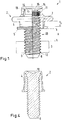
- Fig.1 shows a fastening assembly 1 with a blind rivet 2 and a nut. 3
- the blind rivet screw 2 has a rivet sleeve 4 with a setting head 5 and a deformation region 6 (FIG. Fig. 2 ) for forming a closing head 7 (FIG. Fig. 1 ) on.
- the blind rivet screw 2 also has bolts 8 with an external thread 9, which protrudes with a threaded portion 10 from the setting head 5 and is connected in a connecting region 11 with the rivet sleeve 4.
- Such a blind rivet screw 2 is usually provided for a precisely specified purpose.
- Fig. 1 Therefore, two parameters are shown, which are essential for the respective blind rivet 2.
- the length of the rivet sleeve 4 is matched to the joint material thickness F in order to ensure the correct formation of the closing head 7.
- the joining material may be, for example, a metal sheet or another sheet-like element. It may also be a stack of two or more such elements, which are also connected to each other when setting the blind rivet screw 2.
- Anschraubgutdicke ie the thickness of a Guts, which is to be fastened by means of the blind rivet 2 to the Fügegut.
- the Anschraubdicke thus forms a Anschraubgut-desired area A.
- the tightening target area A then defines the maximum allowable thickness of the intended Anschraubguts.
- the blind rivet screw is dimensioned such that the bolt 8 in the set state of the blind rivet screw 2, that is to say after formation of the closing head 7, protrudes with its threaded portion 10 as far as possible out of the rivet sleeve 4 on the side of the setting head 5, that the external thread after placement of the Anschraubguts protrudes with a maximum of four complete threads on the Anschraubgut.
- a surcharge of 1 mm may be allowed.
- conical tip of the bolt 8, which is thread-free remains outside in this consideration.
- the threaded portion that is, the part of the external thread 9 protruding from the rivet sleeve 4 has a maximum of four threads plus 1 mm longer than the target area A to be screwed on.
- the nut 3 has an internal thread 12 and a maximum of 4 threads.
- the internal thread 12 has a pitch which differs from the pitch of the external thread 9. The difference is at least 2%, but no more than 5%. This makes it possible to unscrew the nut 3 on the bolt 8, even if this requires an increased moment.
- the two threads 9, 12 brace something against each other, so that the loads are distributed more uniformly on the individual threads.
- the bolt 8 When forming the closing head 7, the bolt 8 is pulled out of the rivet sleeve slightly. In unfavorable conditions between the Anschraubgut-desired range A and Fügegutdicke F, it may then happen that with the above dimensioning rule of the threaded portion 10 when setting the blind rivet, so in undeformed state of the rivet 4 is too short to attack with a tool on the external thread 9 of the bolt 8 in order to apply the required to form the closing head 7 traction.
- the bolt 8 is, as in various embodiments of Fig. 3 can be seen formed with a cavity 13.
- the cavity can either be from a front side ( Fig. 3a ) or from the opposite end face ( Fig. 3b ) go out or he can enforce the bolt 8 over its entire length. This also saves mass.
- the bolt 8 has a head 14, which abuts against the rivet sleeve from the side facing away from the setting head 5.
- the bolt 8 has in the attachment area a thread-free retaining contour 15 in the form of a corrugation on which the rivet sleeve 4 is stamped in the connection area 11.
- the rivet sleeve 4 has at least one opening 16 in the connection region. This also saves material.
- Fig. 2 is one opposite Fig. 1 shown modified embodiment in which the bolt 8 is screwed in the connecting portion 11 in the rivet 4.
- the bolt 8 then abuts against a bolt abutment wall 17.
- the bolt abutment wall may simply be a radially inwardly projecting one Be projection of the rivet 4. However, it may also, as shown, be formed as a closed wall and have a contour which deviates from a plane. In the present case, the bolt system wall 17 has a conical depression 18, in which material is again saved.
- connection between the pin 8 and the sleeve 4 is formed in the connection area by a screw, which has a maximum of two threads.
- the bolt 8 is screwed into the connecting region 11 as far as the stop on the bolt system wall 17 and then clamped by applying a slightly larger torque against the bolt system wall 17.
- Such a compound, optionally including a subsequent crimping is sufficient to prevent accidental release.
- a torque on the bolt 8 is applied when screwing the nut 3, which would screw the bolt 8 further into the sleeve 4, so that even in this case accidental release is not to be feared.
- the rivet sleeve 4 on two different wall thicknesses.
- the rivet sleeve 4 has adjacent to the setting head 5 has a smaller wall thickness than adjacent to the connecting portion 11. Shown are two discrete wall thicknesses. But it is also possible that the thickness of the wall of the rivet sleeve 4 tapers continuously or according to another function in the connection region 11 to the setting head 5 out.
- the rivet sleeve 4 has a shape on the outer circumference, which deviates from a cylindrical or a cone shape.
- the rivet 4 has here a number of radially outwardly projecting ribs 19 which reinforce the connecting portion 11, without a corresponding material thickness over the entire circumference would be necessary.
- the same embodiment is also found in the embodiment Fig. 1 ,
- the rivet sleeve 4, but at least the setting head 7 and / or the deformation region 6 are formed from a material or comprise a material in which the ratio between the elastic limit and elongation at break is at least 10%, preferably at least 12%.
- This material thus forms a higher-strength material that can be heavily loaded.
- material can be saved by making the setting head 5 or the wall of the deformation section 6 relatively thin. This results in a total of a blind rivet 2 with a low mass.
- the setting head 5 and / or the deformation zone 6 deformed to the closing head 7 have a comparative strength which is greater than a thread withdrawal force of the external thread 9.
- This comparison strength should preferably be at most 50% higher, in particular at most 25% higher than be the thread extraction force.
- This material can be saved in turn, because the setting head 5 and / or the deformation region 6, which is to be formed to the closing head 7, may be formed relatively massearm.
- the blind rivet screw 2 has the following tasks: It is intended to hold together two or more elements of a material to be joined. It should also provide an external thread 9 available to screw later further elements here. The comparative strength and the thread pull-out force are now matched to one another such that if the thread fails, at least the first task, namely joining, is still maintained.
- Fig. 4 shows a further modified embodiment of a blind rivet screw 2, in which the bolt 8 and the rivet sleeve 4 are integrally formed. in the The rest are in the FIGS. 1 to 3 described features.
- the bolt 8 can also, as in Fig. 3 shown to be provided with a cavity 13.
Abstract
Es wird eine Blindnietschraube 2 angegeben mit einer Niethülse 4, die einen Setzkopf 5 und einen Verformungsbereich zum Ausbilden eines Schließkopfs 7 aufweist, und einen Bolzen 8 mit einem Außengewinde 9, der mit einem Gewindeabschnitt 10 aus dem Setzkopf 5 vorsteht und in einem Verbindungsbereich 11 mit der Niethülse 4 verbunden ist.Man möchte eine Blindnietschraube mit kleiner Masse bereitstellen können.Hierzu ist vorgesehen, dass der Gewindeabschnitt 10 bei ausgebildetem Schließkopf 7 maximal vier Gewindegänge plus 1 mm länger ist als der Anschraubgut-Sollbereich A der Blindnietschraube 2, der Gewindeabschnitt 10 bei unverformter Niethülse 4 mindestens jedoch maximal vier Gewindegänge über die Niethülse 4 vorsteht.A blind rivet screw 2 is specified with a rivet sleeve 4, which has a setting head 5 and a deformation area for forming a closing head 7, and a bolt 8 with an external thread 9, which projects out of the setting head 5 with a threaded section 10 and in a connecting area 11 The rivet sleeve 4 is connected. One would like to be able to provide a blind rivet screw with a small mass. For this purpose, it is provided that the threaded section 10 with a formed closing head 7 is a maximum of four thread turns plus 1 mm longer than the screw-on target area A of the blind rivet screw 2, the threaded section 10 in undeformed rivet sleeve 4 protrudes at least a maximum of four threads over the rivet sleeve 4.
Description
Die vorliegende Erfindung betrifft eine Blindnietschraube mit einer Niethülse, die einen Setzkopf und einen Verformungsbereich zum Ausbilden eines Schließkopfes aufweist, und einem Bolzen mit einem Außengewinde, der mit einem Gewindeabschnitt aus dem Setzkopf vorsteht und in einem Verbindungsbereich mit der Niethülse verbunden ist.The present invention relates to a blind rivet with a rivet sleeve, which has a setting head and a deformation region for forming a closing head, and a bolt with an external thread which protrudes with a threaded portion of the setting head and is connected in a connecting region with the rivet.
Eine derartige Blindnietschraube wird nach Art eines Blindniets in einer Struktur befestigt, die im Folgenden kurz als "Fügegut" bezeichnet wird. Bei der Struktur kann es sich um eine einzelne Platte oder ein Blech handeln. Es kann aber auch um einen Stapel aus zwei oder mehr plattenartigen Gegenständen handeln.Such a blind rivet screw is fastened in the manner of a blind rivet in a structure which is referred to below as "joining material". The structure may be a single plate or a sheet. It but can also be a stack of two or more plate-like objects.
Nach dem Setzen der Blindnietschraube steht der Bolzen mit dem Außengewinde zur Verfügung, um an dem Fügegut weitere Teile zu befestigen. Beispielsweise kann man eine derartige Blindnietschraube in einem Kraftfahrzeug verwenden, um eine Airbag-Einheit mit der Karosserie des Kraftfahrzeugs zu verbinden.After setting the blind rivet screw, the bolt with the external thread is available in order to fasten further parts to the joint material. For example, one can use such a blind rivet screw in a motor vehicle to connect an airbag unit to the body of the motor vehicle.
Allgemein ist ein bevorzugtes Anwendungsgebiet einer derartigen Blindnietschraube die Fahrzeugtechnik, die nicht nur Personenkraftwagen, sondern auch LKW, Eisenbahnwaggons und Flugzeuge umfasst. In diesem Bereich spielt das Gewicht oder die Masse der verwendeten Teile eine relativ große Rolle, weil bei der Bewegung eines derartigen Fahrzeugs diese Masse beschleunigt und abgebremst werden muss.In general, a preferred field of application of such a blind rivet screw is vehicle technology, which includes not only passenger cars but also trucks, railway carriages and airplanes. In this area, the weight or mass of the parts used plays a relatively large role, because during the movement of such a vehicle, this mass must be accelerated and decelerated.
Der Erfindung liegt die Aufgabe zugrunde, eine Blindnietschraube mit kleiner Masse bereitzustellen.The invention has for its object to provide a blind rivet with small mass.
Diese Aufgabe wird bei einer Blindnietschraube der eingangs genannten Art dadurch gelöst, dass der Gewindeabschnitt bei ausgebildetem Schließkopf maximal vier Gewindegänge plus 1 mm länger ist als ein Anschraubgut-Sollbereich der Blindnietschraube, der Gewindeabschnitt bei unverformter Niethülse mindestens jedoch vier Gewindegänge über die Niethülse vorsteht.This object is achieved with a blind rivet screw of the type mentioned above in that the threaded portion with trained closing head a maximum of four threads plus 1 mm longer than a Anschraubgut desired range of Blindnietschraube, the threaded portion protrudes at undeformed rivet but at least four threads on the rivet.
Mit einer derartigen Ausbildung kann die Masse der Blindnietschraube auf ein Minimum beschränkt werden. Der Gewindeabschnitt, der aus dem Setzkopf vorsteht, weist lediglich maximal vier Gewindegänge plus 1 mm auf. Lediglich diese Länge steht damit zum Aufschrauben einer Mutter oder dergleichen zur Verfügung. Diese Länge reicht aber aus, weil bei einer Schraubverbindung zwischen einem Innengewinde und einem Außengewinde ohnehin die Hauptlast der Gewindeverbindung von drei Gewindegängen getragen wird. Wenn der Gewindeabschnitt bei dem ausgebildeten Schließkopf nur um maximal vier Gewindegänge plus 1 mm plus die Dicke des Anschraubgut-Sollbereichs aus der Niethülse vorsteht, dann kann es allerdings sein, dass im unverformten Zustand der Niethülse die aus der Niethülse vorstehende Länge des Gewindeabschnitts zu kurz ist, um ein Werkzeug angreifen zu lassen, das durch Aufbringen einer Zugkraft den Schließkopf erzeugt. Um sicherzustellen, dass ein Werkzeug auf jeden Fall angreifen kann, geht der Gewindeabschnitt mit mindestens vier Gewindegängen aus der Niethülse vor. Eine derartige Situation kann sich beispielsweise dann ergeben, wenn die Dicke des Fügeguts wesentlich größer ist als die Dicke des Anschraubguts. Die Dicke des Anschraubguts, das mit der Blindnietschraube an dem Fügegut befestigt werden soll, bestimmt den Anschraubgut-Sollbereich. Die Länge des Gewindeabschnitts ist also definiert zu mindestens 4 Gewindegängen bei unverformter Niethülse und, sofern sie bei verformter Niethülse mit ausgebildetem Schließknopf dann länger sein könnte, zu maximal 4 Gewindegängen plus 1 mm plus Anschraubgut-Sollbereich.With such a design, the mass of the blind rivet screw can be kept to a minimum. The threaded portion protruding from the setting head only has a maximum of four threads plus 1 mm. Only this length is thus available for screwing a nut or the like. But this length is sufficient because with a screw connection between an internal thread and a External thread anyway the main load of the threaded connection of three threads is worn. If the threaded portion only protrudes from the rivet sleeve by a maximum of four threads plus 1 mm plus the thickness of the set target area, then it may be that in the undeformed condition of the rivet sleeve the length of the threaded portion protruding from the rivet sleeve is too short to engage a tool that generates the closing head by applying a pulling force. To ensure that a tool can engage in any case, the threaded section with at least four threads of the rivet sleeve before. Such a situation may arise, for example, if the thickness of the material to be joined is substantially greater than the thickness of the Anschraubguts. The thickness of the Anschraubguts, which is to be fixed with the Blindnietschraube to the joining material, determines the target mounting area. The length of the threaded portion is thus defined to at least 4 threads with undeformed rivet and, if it could be longer with deformed rivet with trained lock then longer, to a maximum of 4 threads plus 1 mm plus target mounting area.
Bevorzugterweise ist der Gewindeabschnitt bei ausgebildetem Schließkopf maximal vier Gewindegänge länger als der Anschraubgut-Sollbereich. Man spart sich damit die um 1 mm längere Ausbildung der zuvor beschriebenen Ausführungsform. Auch hier gilt allerdings, dass der Gewindeabschnitt bei unverformter Niethülse mindestens vier Gewindegänge über die Niethülse vorsteht.Preferably, the threaded portion is formed with a trained closing head a maximum of four threads longer than the Anschraubgut-desired range. This saves the 1 mm longer training of the embodiment described above. Again, however, that the threaded portion protrudes at undeformed rivet at least four threads on the rivet.
Vorzugsweise weist der Verbindungsbereich mindestens ein Loch auf. Der Verbindungsbereich zwischen dem Bolzen und der Niethülse ist bei einer Blindnietschraube praktisch nur auf Zug belastet. Wenn man hier Material entfernt, lässt sich eine weitere Einsparung bei der Masse der Blindnietschraube erzielen.Preferably, the connection area has at least one hole. The connection area between the bolt and the rivet sleeve is practically only loaded with tension on a blind rivet screw. If you remove material here, you can achieve a further saving in the mass of the blind rivet screw.
Vorzugsweise weist der Verbindungsbereich an seinem vom Setzkopf abgewandten Ende eine radial nach innen weisende Bolzenanlagewand aufweist, wobei die Bolzenanlagewand vorzugsweise geschlossen ist und insbesondere eine Kontur aufweist, die von einer Ebene abweicht. Bei einer derartigen Blindnietschraube ist der Bolzen in die Niethülse, genauer gesagt in den Verbindungsbereich der Niethülse eingeschraubt und zwar so lange, bis er an der Bolzenanlagewand zur Anlage kommt. Wenn bei diesem Einschrauben ein ausreichendes Drehmoment aufgebracht wird, ergibt sich ein Verklemmen zwischen dem Bolzen und dem Verbindungsbereich, was in der Regel ausreicht, um den Bolzen zuverlässig in der Niethülse zu halten. Es hat sich allerdings herausgestellt, dass der größte Teil der Anlagekraft von einem Bereich der Bolzenanlagewand aufgenommen wird, der radial außen liegt. Dementsprechend kann man sich darauf beschränken, die Bolzenanlagewand dort dick zu machen, während sie radial weiter innen eine verminderte Dicke aufweisen kann. Die Dickenverminderung der Bolzenanlagewand kann rampenförmig erfolgen. Im Extremfall kann man in der radialen Mitte der Bolzenanlagewand auch ein Loch vorsehen, um Masse zu sparen.Preferably, the connecting region has at its end facing away from the setting head a radially inwardly facing bolt abutment wall, wherein the bolt abutment wall is preferably closed and in particular has a contour which deviates from a plane. With such a blind rivet screw, the bolt is screwed into the rivet sleeve, more precisely into the connecting area of the rivet sleeve, namely until it comes into contact with the bolt abutment wall. If a sufficient torque is applied during this screwing, results in a jamming between the bolt and the connecting portion, which is usually sufficient to hold the bolt reliably in the rivet. However, it has been found that most of the contact force is absorbed by an area of the bolt abutment wall which lies radially outward. Accordingly, it may be limited to making the bolt abutment wall thick, while radially further inside, it may have a reduced thickness. The reduction in thickness of the bolt system wall can be ramped. In extreme cases, you can also provide a hole in the radial center of the bolt system wall to save mass.
Vorzugsweise weist der Verbindungsbereich ein Gewinde mit maximal zwei Gewindegängen auf. Eine derartige Verbindung reicht aus, um die gewünschten Verspannungskräfte zu erzielen. Mit zwei Gewindegängen ist der Verbindungsbereich in axialer Richtung (bezogen auf die Achse des Bolzens) relativ kurz, so dass man auch hier Material und damit Masse einsparen kann.Preferably, the connection area has a thread with a maximum of two threads. Such a connection is sufficient to achieve the desired bracing forces. With two threads, the connection area in the axial direction (relative to the axis of the bolt) is relatively short, so that one can also save material and thus mass here.
In einer alternativen Ausgestaltung ist vorgesehen, dass der Bolzen im Verbindungsbereich eine gewindefreie Haltekontur aufweist. Diese Haltekontur kann beispielsweise in einer axial verlaufenden Verzahnung bestehen. In diesem Fall wird beim Herstellen der Blindnietschraube eine Niethülse im Verbindungsbereich auf den Bolzen, genauer gesagt seine Haltekontur, aufgepresst.In an alternative embodiment, it is provided that the bolt has a thread-free holding contour in the connection region. This holding contour can for example consist of an axially extending toothing. In this case, when making the blind rivet screw a Rivet sleeve in the connection area on the bolt, more precisely its holding contour, pressed on.
In einer weiteren Ausgestaltung ist vorgesehen, dass der Bolzen und die Niethülse einstückig ausgebildet sind.In a further embodiment it is provided that the bolt and the rivet sleeve are integrally formed.
Bevorzugterweise weist der Setzkopf und/oder der zum Schließkopf umgeformte Verformungsbereich eine Vergleichsfestigkeit auf, die größer ist als eine Gewindeauszugskraft des Außengewindes, wobei die Vergleichsfestigkeit insbesondere maximal 50% höher, insbesondere maximal 25% höher als die Gewindeauszugskraft ist. Der Setzkopf und der Verformungsbereich können dann relativ dünn ausgebildet werden, was sich positiv in einer geringen Masse auswirkt.Preferably, the setting head and / or the deformed to the closing head deformation region has a comparison strength that is greater than a thread extraction force of the external thread, the comparison strength is in particular at most 50% higher, in particular at most 25% higher than the thread extraction force. The setting head and the deformation region can then be made relatively thin, which has a positive effect in a small mass.
Auch ist von Vorteil, wenn die Niethülse zumindest im Bereich von Setzkopf und/oder Verformungsbereich ein Material aufweist, bei dem das Verhältnis zwischen Elastizitätsgrenze und Bruchdehnung mindestens 10%, vorzugsweise mindestens 12% beträgt. Die Elastizitätsgrenze, die auch als 0,2-Prozent-Dehngrenze oder mit der Abkürzung Rp,0,2 bezeichnet wird, ist diejenige mechanische Spannung, bei der die auf die Anfangslänge der Probe bezogene bleibende Dehnung nach Entlastung 0,2% beträgt.
Bei der Verwendung eines Werkstoffs mit dem genannten Verhältnis verwendet man einen höherfesten Werkstoff, bei dem man mit einer geringeren Wandstärke die gleichen mechanischen Eigenschaften wie bei bisher bekannten Blindnietschrauben erreichen kann.It is also advantageous if the rivet sleeve, at least in the region of the setting head and / or deformation region, comprises a material in which the ratio between the elastic limit and the elongation at break is at least 10%, preferably at least 12%. The elastic limit, also referred to as 0.2 percent proof stress or abbreviated R p, 0.2 , is the stress at which the residual elongation after relieving the initial length of the specimen is 0.2%.
When using a material with said ratio is used a higher-strength material, in which one can achieve the same mechanical properties as previously known blind rivet with a smaller wall thickness.
Vorzugsweise weist die Niethülse zwischen dem Setzkopf und dem Verbindungsbereich mindestens zwei unterschiedliche Wandstärken auf. Man kann eine dünnere Wandstärke verwenden, um die Masse der Blindnietschraube zu verringern.The rivet sleeve preferably has at least two different wall thicknesses between the setting head and the connecting region. You can use a thinner wall thickness to reduce the mass of the blind rivet screw.
Hierbei ist bevorzugt, dass die Niethülse angrenzend an den Setzkopf eine geringere Wandstärke als angrenzend an den Verbindungsbereich aufweist. Ein Bereich, der an den Setzkopf angrenzt, wird beim Setzen der Blindnietschraube zumindest teilweise in das Fügegut eingesetzt und wird dann vom Fügegut radial nach außen stabilisiert. In diesem Fall kann man eine relativ geringe Wandstärke verwenden, ohne die Fähigkeit der Blindnietschraube, eine bestimmte Last zu tragen, zu schwächen.It is preferred that the rivet sleeve adjacent to the setting head has a smaller wall thickness than adjacent to the connection region. An area adjacent to the setting head is at least partially inserted into the material to be joined when setting the blind rivet screw and is then stabilized radially outward by the material to be joined. In this case, one can use a relatively small wall thickness without weakening the ability of the blind rivet screw to carry a given load.
Bevorzugterweise weist zumindest ein Abschnitt der Niethülse auf seinem Innen- und/oder Außenumfang eine Form auf, die von einer Zylinder- oder Konusform abweicht. Eine derartige Abweichung kann beispielsweise dadurch gebildet werden, dass die Form des Umfangs durch ein Polygon, eine Wendelform oder mit Rippen gebildet ist. Es ist auch möglich, hier radial nach außen weisende Stege zu verwenden. Wenn man die abweichende Form im Verbindungsbereich verwendet, wird die Festigkeit des Verbindungsbereichs in eine radiale Richtung verstärkt, so dass man bei einer ausreichenden Festigkeit nur wenig Material für den Verbindungsbereich verwenden muss.Preferably, at least a portion of the rivet sleeve on its inner and / or outer periphery has a shape which deviates from a cylindrical or conical shape. Such a deviation can be formed, for example, in that the shape of the circumference is formed by a polygon, a helical shape or ribs. It is also possible to use here radially outwardly facing webs. By using the deviating shape in the joint portion, the strength of the joint portion is strengthened in a radial direction, so that, with sufficient strength, it is necessary to use little material for the joint portion.
In einer bevorzugten Ausgestaltung weist der Bolzen einen Hohlraum auf. Auch dies spart Material und damit Masse ein. Die Lasttrage-Eigenschaften des Bolzens werden durch einen Hohlraum praktisch nicht oder jedenfalls nicht nennenswert negativ beeinflusst.In a preferred embodiment, the bolt has a cavity. This also saves material and thus mass. The load-carrying properties of the bolt are not affected by a cavity practically or at least not significantly negatively.
Die Erfindung betrifft auch eine Befestigungsanordnung mit einer Blindnietschraube, wie zuvor beschrieben, und einer Mutter mit einem Innengewinde, bei der das Innengewinde maximal vier Gewindegänge aufweist.The invention also relates to a fastening arrangement with a blind rivet screw, as described above, and a nut with an internal thread, in which the internal thread has a maximum of four threads.
Mit maximal vier Gewindegängen kann die Mutter in axialer Richtung sehr kurz gehalten werden. Dies spart wiederum Material und damit Masse ein. Bei vier Gewindegängen ist eine ausreichende Befestigungskraft gegeben.With a maximum of four threads, the nut can be kept very short in the axial direction. This in turn saves material and thus mass. With four threads a sufficient fastening force is given.
Hierbei ist bevorzugt, dass das Innengewinde eine erste Steigerung und das Außengewinde eine zweite Steigerung aufweist, wobei sich die erste Steigerung und die zweite Steigerung um mindestens 2% unterscheiden. Damit ist zwar ein Aufschrauben der Mutter auf den Gewindeabschnitt möglich. Es ergibt sich aber ein Verspannen des Innengewindes auf dem Außengewinde, so dass die Lasttrageeigenschaften der einzelnen Gewindegänge etwas stärker aneinander angeglichen werden als bei einer Gewindepaarung, bei der die beiden Steigungen gleich sind.It is preferred that the internal thread has a first increase and the external thread has a second increase, wherein the first increase and the second increase differ by at least 2%. This is indeed a screwing the nut on the threaded portion possible. But it results in a distortion of the internal thread on the external thread, so that the load-carrying properties of the individual threads are slightly more closely matched to each other than in a threaded pairing, in which the two slopes are the same.
Die Erfindung wird im Folgenden anhand von bevorzugten Ausführungsbeispielen in Verbindung mit den Zeichnungen beschrieben. Hierin zeigen:
- Fig. 1
- eine Befestigungsanordnung mit einer Blindnietschraube und einer Mutter,
- Fig. 2
- eine abgewandelte Form einer Blindnietschraube,
- Fig. 3
- verschiedene Ausführungsformen eines Bolzens der Blindnietschraube und
- Fig. 4
- eine dritte Ausführungsform einer Blindnietschraube.
- Fig. 1
- a fastening arrangement with a blind rivet screw and a nut,
- Fig. 2
- a modified form of blind rivet screw,
- Fig. 3
- various embodiments of a bolt of the blind rivet and
- Fig. 4
- a third embodiment of a blind rivet screw.
In allen Figuren sind die gleichen oder einander entsprechende Elemente mit den gleichen Bezugszeichen versehen. Sofern nicht anders angegeben, sind Merkmale, die nur bei einzelnen Ausführungsformen dargestellt sind, auch bei den anderen Ausführungsformen verwendbar.In all figures, the same or corresponding elements are provided with the same reference numerals. Unless otherwise stated, features that are shown only in individual embodiments, also in the other embodiments usable.
Die Blindnietschraube 2 weist eine Niethülse 4 mit einem Setzkopf 5 und einem Verformungsbereich 6 (
Eine derartige Blindnietschraube 2 ist in der Regel für einen genau spezifizierten Anwendungszweck vorgesehen. In
Es handelt sich zum einen um eine Fügegutdicke F. Die Länge der Niethülse 4 ist auf die Fügegutdicke F abgestimmt, um die korrekte Ausbildung des Schließkopfs 7 sicherzustellen. Das Fügegut kann beispielsweise ein Blech oder ein anderes blechartiges Element sein. Es kann sich auch um einen Stapel aus zwei oder mehr derartiger Elemente handeln, die beim Setzen der Blindnietschraube 2 auch miteinander verbunden werden.On the one hand, this is a joining material thickness F. The length of the rivet sleeve 4 is matched to the joint material thickness F in order to ensure the correct formation of the
Zum anderen handelt es sich um eine Anschraubgutdicke, also die Dicke eines Guts, der mithilfe der Blindnietschraube 2 an dem Fügegut befestigt werden soll. Die Anschraubdicke bildet damit einen Anschraubgut-Sollbereich A. In gewissen Grenzen kann man bei dem Anschraubgut eine kleine Variation der Dicke zulassen. Der Anschraubgut-Sollbereich A definiert dann die maximal zulässige Dicke des bestimmungsgemäßen Anschraubguts.On the other hand, it concerns a Anschraubgutdicke, ie the thickness of a Guts, which is to be fastened by means of the
Man dimensioniert die Blindnietschraube so, dass der Bolzen 8 im gesetzten Zustand der Blindnietschraube 2, also nach Ausbildung des Schließkopfs 7, mit seinem Gewindeabschnitt 10 maximal so weit aus der Niethülse 4 auf der Seite des Setzkopfs 5 vorsteht, dass das Außengewinde nach dem Aufsetzen des Anschraubguts mit maximal vier vollständigen Gewindegängen über das Anschraubgut übersteht. Ein Zuschlag von 1 mm ist gegebenenfalls gestattet. Die in
Damit stehen für die Befestigung des Anschraubguts zwar nur vier Gewindegänge zur Verfügung. Da bei einer Schraubverbindung zwischen einer Mutter und einem Gewindebolzen aber ohnehin drei Gewindegänge die meiste Last tragen, lässt sich auch mit vier Gewindegängen eine ausreichende Lasttrageeigenschaft erreichen.Although only four threads are available for attaching the Anschraubguts. Since in a screw connection between a nut and a threaded bolt but already three threads carry most of the load, can be achieved with four threads a sufficient load-bearing property.
Die Mutter 3 weist ein Innengewinde 12 und maximal 4 Gewindegänge auf. Das Innengewinde 12 hat eine Steigung, die sich von der Steigung des Außengewindes 9 unterscheidet. Der Unterschied beträgt mindestens 2%, maximal jedoch 5%. Damit ist es möglich, die Mutter 3 auf den Bolzen 8 aufzuschrauben, auch wenn hierzu ein erhöhtes Moment erforderlich ist. Die beiden Gewinde 9, 12 verspannen sich dabei etwas gegeneinander, so dass die Lasten gleichmäßiger auf die einzelnen Gewindegänge verteilt werden.The
Beim Ausbilden des Schließkopfs 7 wird der Bolzen 8 aus der Niethülse etwas herausgezogen. Bei ungünstigen Verhältnissen zwischen dem Anschraubgut-Sollbereich A und der Fügegutdicke F kann es dann vorkommen, dass mit der oben angegebenen Dimensionierungsvorschrift der Gewindeabschnitt 10 beim Setzen der Blindnietschraube, also im unverformten Zustand der Niethülse 4 zu kurz ist, um mit einem Werkzeug am Außengewinde 9 des Bolzens 8 anzugreifen, um die zum Ausbilden des Schließkopfs 7 erforderliche Zugkraft aufzubringen.When forming the
Es gibt daher eine zweite Bedingung für die Länge des über die Niethülse 4 vorstehenden Gewindeabschnitts. Im unverformten Zustand (
Der Bolzen 8 ist, wie dies in verschiedenen Ausgestaltungen der
Bei der Ausgestaltung nach
Die Niethülse 4 weist im Verbindungsbereich mindestens eine Öffnung 16 auf. Auch dies spart Material ein.The rivet sleeve 4 has at least one
In
Wie man in
Wie man in
Insbesondere im Verbindungsbereich 11 weist die Niethülse 4 eine Form auf dem Außenumfang auf, die von einer Zylinder- oder einer Konusform abweicht. Im vorliegenden Fall weist die Niethülse 4 hier eine Reihe von radial nach außen vorstehenden Rippen 19 auf, die den Verbindungsbereich 11 verstärken, ohne dass eine entsprechende Materialdicke über den gesamten Umfang notwendig wäre. Die gleiche Ausgestaltung findet sich auch bei der Ausführungsform nach
Die Niethülse 4, zumindest aber der Setzkopf 7 und/oder der Verformungsbereich 6, sind aus einem Material gebildet oder weisen ein Material auf, bei dem das Verhältnis zwischen Elastizitätsgrenze und Bruchdehnung mindestens 10%, vorzugsweise mindestens 12% beträgt. Dieses Material bildet also einen höherfesten Werkstoff, der stark belastet werden kann. Bei gleichen Anforderungen an die Belastung lässt sich Material einsparen, indem man den Setzkopf 5 oder die Wand des Verformungsabschnitts 6 relativ dünn ausbildet. Damit ergibt sich insgesamt eine Blindnietschraube 2 mit einer geringen Masse. In allen Ausgestaltungen kann man vorsehen, dass der Setzkopf 5 und/oder der zum Schließkopf 7 umgeformte Verformungsbereich 6 eine Vergleichsfestigkeit aufweist, die größer ist als eine Gewindeauszugskraft des Außengewindes 9. Diese Vergleichsfestigkeit sollte vorzugsweise maximal 50% höher, insbesondere maximal 25% höher als die Gewindeauszugskraft sein. Damit lässt sich wiederum Material einsparen, weil der Setzkopf 5 und/oder der Verformungsbereich 6, der zum Schließkopf 7 ausgebildet werden soll, relativ massearm ausgebildet sein können. Die Blindnietschraube 2 hat folgende Aufgaben: Sie soll zum einen zwei oder mehr Elemente eines Fügeguts zusammenhalten. Sie soll außerdem ein Außengewinde 9 zur Verfügung stellen, um später weitere Elemente hier festschrauben zu können. Die Vergleichsfestigkeit und die Gewindeauszugskraft sind nun so aufeinander abgestimmt, dass bei Versagen des Gewindes zumindest die erste Aufgabe, nämlich das Fügen, noch erhalten bleibt.The rivet sleeve 4, but at least the setting
Claims (15)
Priority Applications (1)
| Application Number | Priority Date | Filing Date | Title |
|---|---|---|---|
| EP18152534.6A EP3514395A1 (en) | 2018-01-19 | 2018-01-19 | Blind rivet screw |
Applications Claiming Priority (1)
| Application Number | Priority Date | Filing Date | Title |
|---|---|---|---|
| EP18152534.6A EP3514395A1 (en) | 2018-01-19 | 2018-01-19 | Blind rivet screw |
Publications (1)
| Publication Number | Publication Date |
|---|---|
| EP3514395A1 true EP3514395A1 (en) | 2019-07-24 |
Family
ID=61017820
Family Applications (1)
| Application Number | Title | Priority Date | Filing Date |
|---|---|---|---|
| EP18152534.6A Pending EP3514395A1 (en) | 2018-01-19 | 2018-01-19 | Blind rivet screw |
Country Status (1)
| Country | Link |
|---|---|
| EP (1) | EP3514395A1 (en) |
Citations (5)
| Publication number | Priority date | Publication date | Assignee | Title |
|---|---|---|---|---|
| DE10001301A1 (en) * | 2000-01-14 | 2001-07-19 | Opel Adam Ag | Nut for mounting components in car has internal threaded section which is mounted in bore in component and upper section which can be deformed using special tool to form collar which fixes nut in place |
| DE10126747A1 (en) * | 2001-05-31 | 2002-12-19 | Gesipa Blindniettechnik | Blind rivet nut and fastening unit |
| EP1918596A1 (en) * | 2006-11-03 | 2008-05-07 | Herbert Schruff | Blind rivet and use thereof |
| EP2594813A1 (en) * | 2011-11-21 | 2013-05-22 | Dregischan, Simone | Blind rivet element |
| EP2910801A1 (en) * | 2014-02-24 | 2015-08-26 | GESIPA Blindniettechnik GmbH | Blind rivet fastener |
-
2018
- 2018-01-19 EP EP18152534.6A patent/EP3514395A1/en active Pending
Patent Citations (5)
| Publication number | Priority date | Publication date | Assignee | Title |
|---|---|---|---|---|
| DE10001301A1 (en) * | 2000-01-14 | 2001-07-19 | Opel Adam Ag | Nut for mounting components in car has internal threaded section which is mounted in bore in component and upper section which can be deformed using special tool to form collar which fixes nut in place |
| DE10126747A1 (en) * | 2001-05-31 | 2002-12-19 | Gesipa Blindniettechnik | Blind rivet nut and fastening unit |
| EP1918596A1 (en) * | 2006-11-03 | 2008-05-07 | Herbert Schruff | Blind rivet and use thereof |
| EP2594813A1 (en) * | 2011-11-21 | 2013-05-22 | Dregischan, Simone | Blind rivet element |
| EP2910801A1 (en) * | 2014-02-24 | 2015-08-26 | GESIPA Blindniettechnik GmbH | Blind rivet fastener |
Similar Documents
| Publication | Publication Date | Title |
|---|---|---|
| EP1918596B1 (en) | Blind rivet and use thereof | |
| DE19749219B4 (en) | Non-removable fastening device | |
| EP3698055A1 (en) | Tolerance compensation assembly | |
| EP1961976B1 (en) | Fastening device | |
| EP3565976B1 (en) | Device for limiting torque with three webs | |
| DE102012221228A1 (en) | Device for compensating tolerances between two screwed components, has spacer ring that acts in axial direction and is moved to component against restoring force of fastener fixedly connected to base element | |
| EP3315799B1 (en) | Blind rivet nut | |
| EP3387270B1 (en) | Fastening element | |
| DE102018117131A1 (en) | Self-punching element and assembly part consisting of the element and a sheet metal part | |
| DE102009024264A1 (en) | Fastener i.e. nut, for screwing-on threaded bolt, has borehole with attachment areas, which exhibit inner diameters adapted to different standard thread diameters of threaded bolt, respectively | |
| EP2018484A1 (en) | Screw-in blind rivet, connecting arrangement with the screw-in blind rivet, and method of connecting two components with the screw-in blind rivet | |
| EP2910801B1 (en) | Blind rivet fastener | |
| WO2020200776A1 (en) | Multipart adjustment element for a tolerance compensation assembly | |
| DE102014207554B4 (en) | Motor vehicle with a ferrule connection assembly | |
| EP2627915A1 (en) | Anchoring device for fastening a component to a carrier element | |
| EP3514395A1 (en) | Blind rivet screw | |
| EP0457249B1 (en) | Trailer coupling key word: securing device with mechanical play | |
| DE2641909A1 (en) | BLIND FASTENER WITH MULTIPLE SLEEVE | |
| DE102012220033A1 (en) | Functional element, particularly nut element for pressing sheet metal unit of component assembly, has head unit to form flange and sheet metal contact surface formed at head unit | |
| DE19734539C2 (en) | Component connection | |
| WO2001038747A1 (en) | Nut with a pressure ring | |
| DE102010055808A1 (en) | fastening device | |
| DE2619728A1 (en) | BLIND FASTENER WITH MULTIPLE SLEEVE | |
| DE202021100435U1 (en) | Frame attachment assembly, door and fasteners | |
| DE102015119874A1 (en) | mounting assembly |
Legal Events
| Date | Code | Title | Description |
|---|---|---|---|
| PUAI | Public reference made under article 153(3) epc to a published international application that has entered the european phase |
Free format text: ORIGINAL CODE: 0009012 |
|
| STAA | Information on the status of an ep patent application or granted ep patent |
Free format text: STATUS: THE APPLICATION HAS BEEN PUBLISHED |
|
| AK | Designated contracting states |
Kind code of ref document: A1 Designated state(s): AL AT BE BG CH CY CZ DE DK EE ES FI FR GB GR HR HU IE IS IT LI LT LU LV MC MK MT NL NO PL PT RO RS SE SI SK SM TR |
|
| AX | Request for extension of the european patent |
Extension state: BA ME |
|
| STAA | Information on the status of an ep patent application or granted ep patent |
Free format text: STATUS: REQUEST FOR EXAMINATION WAS MADE |
|
| 17P | Request for examination filed |
Effective date: 20191203 |
|
| RBV | Designated contracting states (corrected) |
Designated state(s): AL AT BE BG CH CY CZ DE DK EE ES FI FR GB GR HR HU IE IS IT LI LT LU LV MC MK MT NL NO PL PT RO RS SE SI SK SM TR |
|
| STAA | Information on the status of an ep patent application or granted ep patent |
Free format text: STATUS: EXAMINATION IS IN PROGRESS |
|
| STAA | Information on the status of an ep patent application or granted ep patent |
Free format text: STATUS: EXAMINATION IS IN PROGRESS |
|
| 17Q | First examination report despatched |
Effective date: 20201214 |
|
| STAA | Information on the status of an ep patent application or granted ep patent |
Free format text: STATUS: EXAMINATION IS IN PROGRESS |
|
| RAP1 | Party data changed (applicant data changed or rights of an application transferred) |
Owner name: SFS GROUP GERMANY GMBH |
|
| GRAP | Despatch of communication of intention to grant a patent |
Free format text: ORIGINAL CODE: EPIDOSNIGR1 |
|
| STAA | Information on the status of an ep patent application or granted ep patent |
Free format text: STATUS: GRANT OF PATENT IS INTENDED |
|
| INTG | Intention to grant announced |
Effective date: 20240305 |