EP3514101B1 - Crane - Google Patents
Crane Download PDFInfo
- Publication number
- EP3514101B1 EP3514101B1 EP19152992.4A EP19152992A EP3514101B1 EP 3514101 B1 EP3514101 B1 EP 3514101B1 EP 19152992 A EP19152992 A EP 19152992A EP 3514101 B1 EP3514101 B1 EP 3514101B1
- Authority
- EP
- European Patent Office
- Prior art keywords
- crane
- arm
- load
- designed
- stabilising
- Prior art date
- Legal status (The legal status is an assumption and is not a legal conclusion. Google has not performed a legal analysis and makes no representation as to the accuracy of the status listed.)
- Active
Links
- 230000003019 stabilising effect Effects 0.000 claims description 23
- 230000000284 resting effect Effects 0.000 claims description 10
- 230000003213 activating effect Effects 0.000 claims description 2
- 238000000034 method Methods 0.000 description 3
- 238000010586 diagram Methods 0.000 description 2
- 238000011144 upstream manufacturing Methods 0.000 description 2
- 230000000694 effects Effects 0.000 description 1
- 238000012986 modification Methods 0.000 description 1
- 230000004048 modification Effects 0.000 description 1
Images


Classifications
-
- B—PERFORMING OPERATIONS; TRANSPORTING
- B66—HOISTING; LIFTING; HAULING
- B66C—CRANES; LOAD-ENGAGING ELEMENTS OR DEVICES FOR CRANES, CAPSTANS, WINCHES, OR TACKLES
- B66C23/00—Cranes comprising essentially a beam, boom, or triangular structure acting as a cantilever and mounted for translatory of swinging movements in vertical or horizontal planes or a combination of such movements, e.g. jib-cranes, derricks, tower cranes
- B66C23/88—Safety gear
- B66C23/90—Devices for indicating or limiting lifting moment
- B66C23/905—Devices for indicating or limiting lifting moment electrical
-
- B—PERFORMING OPERATIONS; TRANSPORTING
- B60—VEHICLES IN GENERAL
- B60P—VEHICLES ADAPTED FOR LOAD TRANSPORTATION OR TO TRANSPORT, TO CARRY, OR TO COMPRISE SPECIAL LOADS OR OBJECTS
- B60P1/00—Vehicles predominantly for transporting loads and modified to facilitate loading, consolidating the load, or unloading
- B60P1/54—Vehicles predominantly for transporting loads and modified to facilitate loading, consolidating the load, or unloading using cranes for self-loading or self-unloading
- B60P1/5404—Vehicles predominantly for transporting loads and modified to facilitate loading, consolidating the load, or unloading using cranes for self-loading or self-unloading with a fixed base
- B60P1/5423—Vehicles predominantly for transporting loads and modified to facilitate loading, consolidating the load, or unloading using cranes for self-loading or self-unloading with a fixed base attached to the loading platform or similar
- B60P1/5433—Vehicles predominantly for transporting loads and modified to facilitate loading, consolidating the load, or unloading using cranes for self-loading or self-unloading with a fixed base attached to the loading platform or similar and having the first pivot on a vertical axis
-
- B—PERFORMING OPERATIONS; TRANSPORTING
- B66—HOISTING; LIFTING; HAULING
- B66C—CRANES; LOAD-ENGAGING ELEMENTS OR DEVICES FOR CRANES, CAPSTANS, WINCHES, OR TACKLES
- B66C13/00—Other constructional features or details
- B66C13/18—Control systems or devices
- B66C13/40—Applications of devices for transmitting control pulses; Applications of remote control devices
-
- B—PERFORMING OPERATIONS; TRANSPORTING
- B66—HOISTING; LIFTING; HAULING
- B66C—CRANES; LOAD-ENGAGING ELEMENTS OR DEVICES FOR CRANES, CAPSTANS, WINCHES, OR TACKLES
- B66C23/00—Cranes comprising essentially a beam, boom, or triangular structure acting as a cantilever and mounted for translatory of swinging movements in vertical or horizontal planes or a combination of such movements, e.g. jib-cranes, derricks, tower cranes
- B66C23/62—Constructional features or details
- B66C23/64—Jibs
- B66C23/70—Jibs constructed of sections adapted to be assembled to form jibs or various lengths
- B66C23/701—Jibs constructed of sections adapted to be assembled to form jibs or various lengths telescopic
Definitions
- This invention relates to a crane for moving loads.
- the crane is, in particular, mounted on a respective movable transport vehicle, preferably in the form of a vehicle movable on the road, in particular the vehicle being in the form of a truck which has a respective box for supporting the load in which is positioned the crane.
- the prior art cranes comprise an arm for supporting the load which is telescopically movable in a plurality of positions of extension included between a retracted position and a position of maximum extension and which comprises a plurality of sliding members, and have the respective supporting arm which is rotatable angularly, in particular horizontally, relative to a respective axis of rotation of the crane and can therefore be positioned in different angular positions of rotation.
- the prior art cranes also comprise means which are designed to stabilise the crane to avoid the risk of overturning during the working operations of the arm, the stabilising means being configurable in a plurality of stabilising configurations of the crane.
- the present invention therefore proposes a new and/or alternative solution to the solutions known up to now and, more specifically, proposes to overcome one or more of the above mentioned drawbacks or problems and/or to meet one or more of the needs felt in the trade or inferable from the above.
- a crane is therefore provided for moving loads, in particular mounted on a respective movable transport vehicle, preferably in the form of a vehicle movable on the road, in particular the vehicle being in the form of a truck which has a respective box for supporting the load in which is positioned the crane;
- the crane comprising an arm for supporting the load which is telescopically movable in a plurality of positions of extension included between a retracted position and a position of maximum extension and which comprises a plurality of sliding members;
- the supporting arm being rotatable angularly, in particular horizontally, relative to a respective axis of rotation of the crane and it can be positioned in different angular positions of rotation;
- the crane also comprising means which are designed to stabilise the crane to avoid the risk of overturning during the working operations of the arm, the stabilising means being configurable in a plurality of stabilising configurations of the crane.
- It comprises means which are designed to indicate, in particular to the user of the crane, the maximum load which can be lifted by the crane, that is to say, by the arm of the crane, as a function of the condition of extension of the arm and/or the respective angular position of rotation of the arm.
- the indicator means are located at the control means of the crane; characterised in that the indicator means comprise a respective screen page, on a corresponding display unit of the crane, the screen page comprising symbols indicating the number of sliding members which are in an extended condition.
- the screen page comprises a plurality of zones, in particular situated at the symbols, in particular alongside the symbols, in which is indicated, or displayed, the respective value of the maximum load in the respective condition of extension of the arm of the crane.
- the screen page comprising an area in which is indicated, or displayed, the respective angular position of rotation for which are indicated, or displayed, the values of maximum load which can be lifted.
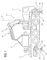
- FIG. 1 illustrates a preferred embodiment of a crane 10 for moving loads 13, in particular mounted on a respective movable transport vehicle, preferably in the form of a vehicle movable on the road, in particular the vehicle being in the form of a truck 11 which has a respective box for supporting the load 111 in which is positioned the crane 10.
- the crane 10 comprises an arm 12 for supporting the load 13 which is telescopically movable in a plurality of positions of extension included between a retracted position and a position of maximum extension and which comprises a plurality of sliding members 121.
- the supporting arm 12 is rotatable angularly, in particular horizontally, relative to a respective axis of rotation "P" of the crane 12 and it can be positioned in different angular positions of rotation, in particular situated along an angular range of extension of 360°.
- the crane 10 also comprising means 14 which are designed to stabilise the crane 12 to avoid the risk of overturning during the working operations of the arm 12, the stabilising means 14 being configurable in a plurality of stabilising configurations of the crane 12, as described in more detail below.
- each sliding member 121 is movable, in particular slidable, relative to the adjacent sliding member between a respective retracted position relative to the adjacent, or upstream, sliding member 121 and a respective extended position relative to the adjacent, or upstream, sliding member 121, for respectively extending and withdrawing the arm 12.
- the arm 12 for moving the load 13 can be positioned in respective inclined positions, in particular inclined with respect to a corresponding horizontal plane, between a maximum angular or inclined position, wherein the arm 12 can reach the maximum height for moving the load 13, and a minimum angular or inclined position, wherein the arm 12 can reach the minimum height for moving the load 13.
- the means 14 which are designed to stabilise the crane 12 to avoid the risk of overturning during the working operations of the arm 12 comprise one or more elements, or feet, for resting on the ground, 141, in particular in this embodiment there are four feet 141 resting on the ground which are each supported by the end of the rod of a respective jack preferably vertical 140 which can each be respectively positioned in a plurality of stabilising positions of the crane 12, between a respective position close to the crane 12, or to the vehicle 11 supporting the crane 12), and a position furthest away from the crane 12, or the vehicle 11 for supporting the crane 12.
- the elements, or feet, for resting on the ground, 141 which are supported at the end of the rod of respective vertical jacks 140, are supported by respective sliding members 142 which are movable, in particular transversely or horizontally, between a position retracted in a corresponding housing 143 fixed to the vehicle 11, and a maximum extension position wherein the sliding members 142 are outside the housing, in particular tubular, 143.
- the means 14 which are designed to stabilise the crane 12 are fixed, or extend, from the frame of the vehicle for supporting the crane, in particular laterally to the latter.
- means 18 which are designed to indicate, in particular to the user of the crane 10, the maximum load which can be lifted by the crane, that is to say, by the arm of the crane 10, as a function of the condition of extension of the arm 12 and/or the respective angular position of rotation of the arm 12.
- the means 18 for indicating the maximum load which can be lifted by the crane are in the form of means which display the maximum load which can be lifted.
- the indicator means 18 are provided at the means 16 for controlling the crane 12, in particular for controlling the load movement arm 12 of the crane 10.
- control means of the crane 10, or of the arm 12 comprise a display unit 15 and respective manual control means, in particular in the form of pushbuttons and/or respective control levers 160, which can be suitably operated by the user.
- the display unit 15 of the means 16 for controlling the crane 12, in particular for controlling the load movement arm 12 of the crane 10, is designed to define the means 18 for indicating the maximum load which can be lifted.
- the means 16 for controlling the crane 12, in particular the load movement arm 12 of the crane 10 are in the form of a remote control device, in particular portable, having a respective display unit 15.
- the means 18 which are designed to indicate to the user the maximum load which can be lifted by the crane 10, that is to say, by the arm 12 of the crane 10, indicate, in particular progressively, for the respective angular position of rotation 182, the maximum load which can be lifted as a function of the number of sliding members 121 of the arm 12 which are in the extended condition.
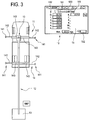
- the means 18 which are designed to indicate to the user the load which can be lifted by the crane 10, that is to say, the load which can be lifted by the arm 12 of the crane 10, provide, or comprise, a respective screen page, on a corresponding display unit 15 of the crane 12, the screen page comprising symbols 180 indicating the number of sliding members 121 which are in the extended condition or not; the symbols being in particular, as illustrated in Figures 3 to 5 , in the form of a sequence of natural numbers between the number zero and the number of the sliding members 121 of the respective arm 12 of the crane 10.
- the means 18 which are designed to indicate to the user the load which can be lifted by the crane 10, that is to say, the load which can be lifted by the arm (12) of the crane 10, provide a respective screen page, on a corresponding display unit 15 of the crane 12, the screen page comprising a plurality of zones 181, in particular situated at the symbols, in particular alongside the symbols 180, in which is indicated, or displayed, the respective value, for example, as illustrated, expressed in kilograms, of the maximum load which can be lifted by the crane 10, or by the arm 12 of the crane 10, in the corresponding working condition, that is, in the respective condition of extension of the arm 12 of the crane 10.
- the means 18 which are designed to indicate to the user the load which can be lifted by the crane 10, that is to say, the load which can be lifted by the arm 12 of the crane 10, provide a respective screen page, on a corresponding display unit 15 of the crane 12, the screen page comprising an area 182 in which is indicated, or displayed, the respective angular position of rotation for which are indicated, or displayed, the values of maximum load which can be lifted 181.
- the means for determining, or calculating, the maximum load which can be lifted by the crane 12, that is to say, by the arm 12 of the crane 10, as a function of the condition of extension of the arm 12 and/or the respective angular position of rotation of the arm 12, comprise respective means 22 which measure the specific configuration of the stabilising means 14 of the crane 12, in the respective working condition, in particular the configuration being defined by the respective condition or the extension position of the sliding members 142 for supporting the means 141 for resting on the ground of the stabilising means 14.
- the means 22 designed to measure the configuration of the stabilising means 14 comprise sensor means, which are not illustrated in detail in the accompanying drawings, which are designed to measure the length of extension of the sliding members 142 which carry the respective means 14 for resting on the ground.
- the means designed to indicate to the user the load which can be lifted by the crane 10, that is to say, by the arm 12 of the crane 10, comprise respective means 26, in particular including, or in the form of corresponding, software means or program instructions, which are designed to calculate the limit of stability point by point around the crane 10, in particular as a function of the configuration of the stabilising means 14 of the crane 12.
- the means designed to indicate to the user the load which can be lifted by the crane 10, that is to say, by the arm 12 of the crane 10, comprise respective means 28, in particular including, or in the form of corresponding, software means, which are designed to create a table which, for each angular position of rotation, associates with the respective number of sliding members 121 in the extended condition the relative maximum load value which can be lifted, in particular as a function of the configuration of the stabilising means 14 of the crane 12.
- the means which are designed to indicate to the user the load which can be lifted by the crane 10, that is to say, by the arm 12 of the crane 10, comprise respective means, in particular including or in the form of corresponding software means, which are designed to display, on the display unit 15, in particular of the crane, that is, in the respective area 181 of this, for the respective angular position of the arm indicated in the respective area 182, the value of maximum load which can be lifted that can be associated to the respective number of sliding members 121 in the extended condition, with the values of maximum load which can be lifted which are taken from the table created in the step 28.
Landscapes
- Engineering & Computer Science (AREA)
- Mechanical Engineering (AREA)
- Transportation (AREA)
- Automation & Control Theory (AREA)
- Control And Safety Of Cranes (AREA)
Applications Claiming Priority (1)
| Application Number | Priority Date | Filing Date | Title |
|---|---|---|---|
| IT201800001688A IT201800001688A1 (it) | 2018-01-23 | 2018-01-23 | Gru |
Publications (2)
| Publication Number | Publication Date |
|---|---|
| EP3514101A1 EP3514101A1 (en) | 2019-07-24 |
| EP3514101B1 true EP3514101B1 (en) | 2021-03-17 |
Family
ID=62044837
Family Applications (1)
| Application Number | Title | Priority Date | Filing Date |
|---|---|---|---|
| EP19152992.4A Active EP3514101B1 (en) | 2018-01-23 | 2019-01-22 | Crane |
Country Status (3)
| Country | Link |
|---|---|
| EP (1) | EP3514101B1 (it) |
| DK (1) | DK3514101T3 (it) |
| IT (1) | IT201800001688A1 (it) |
Family Cites Families (4)
| Publication number | Priority date | Publication date | Assignee | Title |
|---|---|---|---|---|
| US4211332A (en) | 1978-04-03 | 1980-07-08 | R O Corporation | Color coded boom and chart system |
| JP2000034093A (ja) | 1998-07-21 | 2000-02-02 | Kobe Steel Ltd | 旋回式作業機械とその安全作業領域及び定格荷重の設定方法 |
| DE102014105618A1 (de) | 2014-04-22 | 2015-10-22 | Terex Cranes Germany Gmbh | Verfahren und Vorrichtung zum Betreiben eines Mobilkrans sowie Mobilkran |
| JP6231727B1 (ja) | 2016-02-03 | 2017-11-15 | 株式会社タダノ | 遠隔操作端末および移動式クレーンの遠隔操作システム |
-
2018
- 2018-01-23 IT IT201800001688A patent/IT201800001688A1/it unknown
-
2019
- 2019-01-22 DK DK19152992.4T patent/DK3514101T3/da active
- 2019-01-22 EP EP19152992.4A patent/EP3514101B1/en active Active
Non-Patent Citations (1)
| Title |
|---|
| None * |
Also Published As
| Publication number | Publication date |
|---|---|
| EP3514101A1 (en) | 2019-07-24 |
| DK3514101T3 (da) | 2021-06-14 |
| IT201800001688A1 (it) | 2019-07-23 |
Similar Documents
| Publication | Publication Date | Title |
|---|---|---|
| US7252203B2 (en) | Mobile crane having a superlift device | |
| EP2616382B3 (en) | Controller for use with a machine, machine including said controller, and method for controlling a machine. | |
| JP6097441B1 (ja) | クレーン作業補助装置 | |
| JP6594559B2 (ja) | 制御部およびモバイル制御モジュールから成る装置 | |
| US9957141B2 (en) | Method for determining the load capacity of cranes | |
| JP6624173B2 (ja) | 過負荷防止装置 | |
| JP2013199349A (ja) | 作業機械 | |
| JP6620798B2 (ja) | 過負荷防止装置 | |
| US10336588B2 (en) | Mobile crane | |
| JP6053141B2 (ja) | 作業確認装置 | |
| JP6258598B2 (ja) | クレーンのアウトリガーの接地検出機構およびクレーンの転倒防止システム | |
| US6779961B2 (en) | Material handler with electronic load chart | |
| EP3514101B1 (en) | Crane | |
| JP2773854B2 (ja) | 作業車の作業表示装置 | |
| EP4077198A1 (en) | System and method for monitoring crane and crane having the same | |
| KR101038523B1 (ko) | 고소작업차량의 작업반경 제어장치 | |
| JP2007031977A (ja) | 杭打機 | |
| GB2353513A (en) | Crane lifting capacity optimisation | |
| JP7516141B2 (ja) | 建設機械の重量計測装置及び建設機械 | |
| US10913643B1 (en) | Dual boom load monitoring | |
| US20190241407A1 (en) | Suspended load calculation device | |
| JP2019104551A (ja) | 移動式クレーン | |
| CN207903797U (zh) | 一种可移动式悬臂吊装置 | |
| JP2016113218A (ja) | 地切り補助装置 | |
| JP2019006565A (ja) | クレーン |
Legal Events
| Date | Code | Title | Description |
|---|---|---|---|
| PUAI | Public reference made under article 153(3) epc to a published international application that has entered the european phase |
Free format text: ORIGINAL CODE: 0009012 |
|
| STAA | Information on the status of an ep patent application or granted ep patent |
Free format text: STATUS: THE APPLICATION HAS BEEN PUBLISHED |
|
| AK | Designated contracting states |
Kind code of ref document: A1 Designated state(s): AL AT BE BG CH CY CZ DE DK EE ES FI FR GB GR HR HU IE IS IT LI LT LU LV MC MK MT NL NO PL PT RO RS SE SI SK SM TR |
|
| AX | Request for extension of the european patent |
Extension state: BA ME |
|
| STAA | Information on the status of an ep patent application or granted ep patent |
Free format text: STATUS: REQUEST FOR EXAMINATION WAS MADE |
|
| 17P | Request for examination filed |
Effective date: 20190927 |
|
| RBV | Designated contracting states (corrected) |
Designated state(s): AL AT BE BG CH CY CZ DE DK EE ES FI FR GB GR HR HU IE IS IT LI LT LU LV MC MK MT NL NO PL PT RO RS SE SI SK SM TR |
|
| STAA | Information on the status of an ep patent application or granted ep patent |
Free format text: STATUS: EXAMINATION IS IN PROGRESS |
|
| 17Q | First examination report despatched |
Effective date: 20200312 |
|
| GRAP | Despatch of communication of intention to grant a patent |
Free format text: ORIGINAL CODE: EPIDOSNIGR1 |
|
| STAA | Information on the status of an ep patent application or granted ep patent |
Free format text: STATUS: GRANT OF PATENT IS INTENDED |
|
| INTG | Intention to grant announced |
Effective date: 20201002 |
|
| RAP1 | Party data changed (applicant data changed or rights of an application transferred) |
Owner name: EFFER S.P.A. |
|
| GRAS | Grant fee paid |
Free format text: ORIGINAL CODE: EPIDOSNIGR3 |
|
| GRAA | (expected) grant |
Free format text: ORIGINAL CODE: 0009210 |
|
| STAA | Information on the status of an ep patent application or granted ep patent |
Free format text: STATUS: THE PATENT HAS BEEN GRANTED |
|
| AK | Designated contracting states |
Kind code of ref document: B1 Designated state(s): AL AT BE BG CH CY CZ DE DK EE ES FI FR GB GR HR HU IE IS IT LI LT LU LV MC MK MT NL NO PL PT RO RS SE SI SK SM TR |
|
| REG | Reference to a national code |
Ref country code: GB Ref legal event code: FG4D |
|
| REG | Reference to a national code |
Ref country code: CH Ref legal event code: EP |
|
| REG | Reference to a national code |
Ref country code: DE Ref legal event code: R096 Ref document number: 602019003145 Country of ref document: DE |
|
| REG | Reference to a national code |
Ref country code: IE Ref legal event code: FG4D |
|
| REG | Reference to a national code |
Ref country code: AT Ref legal event code: REF Ref document number: 1372072 Country of ref document: AT Kind code of ref document: T Effective date: 20210415 |
|
| REG | Reference to a national code |
Ref country code: DK Ref legal event code: T3 Effective date: 20210608 |
|
| RAP4 | Party data changed (patent owner data changed or rights of a patent transferred) |
Owner name: EFFER S.R.L. |
|
| REG | Reference to a national code |
Ref country code: LT Ref legal event code: MG9D |
|
| PG25 | Lapsed in a contracting state [announced via postgrant information from national office to epo] |
Ref country code: NO Free format text: LAPSE BECAUSE OF FAILURE TO SUBMIT A TRANSLATION OF THE DESCRIPTION OR TO PAY THE FEE WITHIN THE PRESCRIBED TIME-LIMIT Effective date: 20210617 Ref country code: BG Free format text: LAPSE BECAUSE OF FAILURE TO SUBMIT A TRANSLATION OF THE DESCRIPTION OR TO PAY THE FEE WITHIN THE PRESCRIBED TIME-LIMIT Effective date: 20210617 Ref country code: FI Free format text: LAPSE BECAUSE OF FAILURE TO SUBMIT A TRANSLATION OF THE DESCRIPTION OR TO PAY THE FEE WITHIN THE PRESCRIBED TIME-LIMIT Effective date: 20210317 Ref country code: GR Free format text: LAPSE BECAUSE OF FAILURE TO SUBMIT A TRANSLATION OF THE DESCRIPTION OR TO PAY THE FEE WITHIN THE PRESCRIBED TIME-LIMIT Effective date: 20210618 Ref country code: HR Free format text: LAPSE BECAUSE OF FAILURE TO SUBMIT A TRANSLATION OF THE DESCRIPTION OR TO PAY THE FEE WITHIN THE PRESCRIBED TIME-LIMIT Effective date: 20210317 |
|
| REG | Reference to a national code |
Ref country code: NL Ref legal event code: MP Effective date: 20210317 |
|
| PG25 | Lapsed in a contracting state [announced via postgrant information from national office to epo] |
Ref country code: SE Free format text: LAPSE BECAUSE OF FAILURE TO SUBMIT A TRANSLATION OF THE DESCRIPTION OR TO PAY THE FEE WITHIN THE PRESCRIBED TIME-LIMIT Effective date: 20210317 Ref country code: RS Free format text: LAPSE BECAUSE OF FAILURE TO SUBMIT A TRANSLATION OF THE DESCRIPTION OR TO PAY THE FEE WITHIN THE PRESCRIBED TIME-LIMIT Effective date: 20210317 Ref country code: LV Free format text: LAPSE BECAUSE OF FAILURE TO SUBMIT A TRANSLATION OF THE DESCRIPTION OR TO PAY THE FEE WITHIN THE PRESCRIBED TIME-LIMIT Effective date: 20210317 |
|
| PG25 | Lapsed in a contracting state [announced via postgrant information from national office to epo] |
Ref country code: NL Free format text: LAPSE BECAUSE OF FAILURE TO SUBMIT A TRANSLATION OF THE DESCRIPTION OR TO PAY THE FEE WITHIN THE PRESCRIBED TIME-LIMIT Effective date: 20210317 |
|
| REG | Reference to a national code |
Ref country code: AT Ref legal event code: PC Ref document number: 1372072 Country of ref document: AT Kind code of ref document: T Owner name: EFFER S.R.L., IT Effective date: 20210824 |
|
| PG25 | Lapsed in a contracting state [announced via postgrant information from national office to epo] |
Ref country code: LT Free format text: LAPSE BECAUSE OF FAILURE TO SUBMIT A TRANSLATION OF THE DESCRIPTION OR TO PAY THE FEE WITHIN THE PRESCRIBED TIME-LIMIT Effective date: 20210317 Ref country code: CZ Free format text: LAPSE BECAUSE OF FAILURE TO SUBMIT A TRANSLATION OF THE DESCRIPTION OR TO PAY THE FEE WITHIN THE PRESCRIBED TIME-LIMIT Effective date: 20210317 Ref country code: EE Free format text: LAPSE BECAUSE OF FAILURE TO SUBMIT A TRANSLATION OF THE DESCRIPTION OR TO PAY THE FEE WITHIN THE PRESCRIBED TIME-LIMIT Effective date: 20210317 Ref country code: SM Free format text: LAPSE BECAUSE OF FAILURE TO SUBMIT A TRANSLATION OF THE DESCRIPTION OR TO PAY THE FEE WITHIN THE PRESCRIBED TIME-LIMIT Effective date: 20210317 |
|
| PG25 | Lapsed in a contracting state [announced via postgrant information from national office to epo] |
Ref country code: SK Free format text: LAPSE BECAUSE OF FAILURE TO SUBMIT A TRANSLATION OF THE DESCRIPTION OR TO PAY THE FEE WITHIN THE PRESCRIBED TIME-LIMIT Effective date: 20210317 Ref country code: RO Free format text: LAPSE BECAUSE OF FAILURE TO SUBMIT A TRANSLATION OF THE DESCRIPTION OR TO PAY THE FEE WITHIN THE PRESCRIBED TIME-LIMIT Effective date: 20210317 Ref country code: PT Free format text: LAPSE BECAUSE OF FAILURE TO SUBMIT A TRANSLATION OF THE DESCRIPTION OR TO PAY THE FEE WITHIN THE PRESCRIBED TIME-LIMIT Effective date: 20210719 Ref country code: PL Free format text: LAPSE BECAUSE OF FAILURE TO SUBMIT A TRANSLATION OF THE DESCRIPTION OR TO PAY THE FEE WITHIN THE PRESCRIBED TIME-LIMIT Effective date: 20210317 Ref country code: IS Free format text: LAPSE BECAUSE OF FAILURE TO SUBMIT A TRANSLATION OF THE DESCRIPTION OR TO PAY THE FEE WITHIN THE PRESCRIBED TIME-LIMIT Effective date: 20210717 |
|
| REG | Reference to a national code |
Ref country code: DE Ref legal event code: R097 Ref document number: 602019003145 Country of ref document: DE |
|
| PLBE | No opposition filed within time limit |
Free format text: ORIGINAL CODE: 0009261 |
|
| STAA | Information on the status of an ep patent application or granted ep patent |
Free format text: STATUS: NO OPPOSITION FILED WITHIN TIME LIMIT |
|
| PG25 | Lapsed in a contracting state [announced via postgrant information from national office to epo] |
Ref country code: AL Free format text: LAPSE BECAUSE OF FAILURE TO SUBMIT A TRANSLATION OF THE DESCRIPTION OR TO PAY THE FEE WITHIN THE PRESCRIBED TIME-LIMIT Effective date: 20210317 Ref country code: ES Free format text: LAPSE BECAUSE OF FAILURE TO SUBMIT A TRANSLATION OF THE DESCRIPTION OR TO PAY THE FEE WITHIN THE PRESCRIBED TIME-LIMIT Effective date: 20210317 |
|
| 26N | No opposition filed |
Effective date: 20211220 |
|
| PG25 | Lapsed in a contracting state [announced via postgrant information from national office to epo] |
Ref country code: SI Free format text: LAPSE BECAUSE OF FAILURE TO SUBMIT A TRANSLATION OF THE DESCRIPTION OR TO PAY THE FEE WITHIN THE PRESCRIBED TIME-LIMIT Effective date: 20210317 |
|
| PG25 | Lapsed in a contracting state [announced via postgrant information from national office to epo] |
Ref country code: IS Free format text: LAPSE BECAUSE OF FAILURE TO SUBMIT A TRANSLATION OF THE DESCRIPTION OR TO PAY THE FEE WITHIN THE PRESCRIBED TIME-LIMIT Effective date: 20210717 |
|
| PGFP | Annual fee paid to national office [announced via postgrant information from national office to epo] |
Ref country code: FR Payment date: 20220126 Year of fee payment: 4 |
|
| REG | Reference to a national code |
Ref country code: DE Ref legal event code: R081 Ref document number: 602019003145 Country of ref document: DE Owner name: HIAB AB, SE Free format text: FORMER OWNER: EFFER S.P.A., MINERBIO, IT |
|
| REG | Reference to a national code |
Ref country code: GB Ref legal event code: 732E Free format text: REGISTERED BETWEEN 20220714 AND 20220720 |
|
| PG25 | Lapsed in a contracting state [announced via postgrant information from national office to epo] |
Ref country code: MC Free format text: LAPSE BECAUSE OF FAILURE TO SUBMIT A TRANSLATION OF THE DESCRIPTION OR TO PAY THE FEE WITHIN THE PRESCRIBED TIME-LIMIT Effective date: 20210317 |
|
| REG | Reference to a national code |
Ref country code: CH Ref legal event code: PL |
|
| REG | Reference to a national code |
Ref country code: BE Ref legal event code: MM Effective date: 20220131 |
|
| PG25 | Lapsed in a contracting state [announced via postgrant information from national office to epo] |
Ref country code: LU Free format text: LAPSE BECAUSE OF NON-PAYMENT OF DUE FEES Effective date: 20220122 |
|
| PG25 | Lapsed in a contracting state [announced via postgrant information from national office to epo] |
Ref country code: BE Free format text: LAPSE BECAUSE OF NON-PAYMENT OF DUE FEES Effective date: 20220131 |
|
| REG | Reference to a national code |
Ref country code: AT Ref legal event code: PC Ref document number: 1372072 Country of ref document: AT Kind code of ref document: T Owner name: HIAB AB, SE Effective date: 20221018 |
|
| PG25 | Lapsed in a contracting state [announced via postgrant information from national office to epo] |
Ref country code: LI Free format text: LAPSE BECAUSE OF NON-PAYMENT OF DUE FEES Effective date: 20220131 Ref country code: CH Free format text: LAPSE BECAUSE OF NON-PAYMENT OF DUE FEES Effective date: 20220131 |
|
| PG25 | Lapsed in a contracting state [announced via postgrant information from national office to epo] |
Ref country code: IE Free format text: LAPSE BECAUSE OF NON-PAYMENT OF DUE FEES Effective date: 20220122 |
|
| REG | Reference to a national code |
Ref country code: AT Ref legal event code: UEP Ref document number: 1372072 Country of ref document: AT Kind code of ref document: T Effective date: 20210317 |
|
| GBPC | Gb: european patent ceased through non-payment of renewal fee |
Effective date: 20230122 |
|
| PG25 | Lapsed in a contracting state [announced via postgrant information from national office to epo] |
Ref country code: GB Free format text: LAPSE BECAUSE OF NON-PAYMENT OF DUE FEES Effective date: 20230122 |
|
| PG25 | Lapsed in a contracting state [announced via postgrant information from national office to epo] |
Ref country code: FR Free format text: LAPSE BECAUSE OF NON-PAYMENT OF DUE FEES Effective date: 20230131 |
|
| PGFP | Annual fee paid to national office [announced via postgrant information from national office to epo] |
Ref country code: AT Payment date: 20240118 Year of fee payment: 6 |
|
| PG25 | Lapsed in a contracting state [announced via postgrant information from national office to epo] |
Ref country code: MK Free format text: LAPSE BECAUSE OF FAILURE TO SUBMIT A TRANSLATION OF THE DESCRIPTION OR TO PAY THE FEE WITHIN THE PRESCRIBED TIME-LIMIT Effective date: 20210317 Ref country code: CY Free format text: LAPSE BECAUSE OF FAILURE TO SUBMIT A TRANSLATION OF THE DESCRIPTION OR TO PAY THE FEE WITHIN THE PRESCRIBED TIME-LIMIT Effective date: 20210317 |
|
| PGFP | Annual fee paid to national office [announced via postgrant information from national office to epo] |
Ref country code: DE Payment date: 20240129 Year of fee payment: 6 |
|
| PG25 | Lapsed in a contracting state [announced via postgrant information from national office to epo] |
Ref country code: HU Free format text: LAPSE BECAUSE OF FAILURE TO SUBMIT A TRANSLATION OF THE DESCRIPTION OR TO PAY THE FEE WITHIN THE PRESCRIBED TIME-LIMIT; INVALID AB INITIO Effective date: 20190122 |
|
| PGFP | Annual fee paid to national office [announced via postgrant information from national office to epo] |
Ref country code: IT Payment date: 20240123 Year of fee payment: 6 Ref country code: DK Payment date: 20240125 Year of fee payment: 6 |
|
| PG25 | Lapsed in a contracting state [announced via postgrant information from national office to epo] |
Ref country code: TR Free format text: LAPSE BECAUSE OF FAILURE TO SUBMIT A TRANSLATION OF THE DESCRIPTION OR TO PAY THE FEE WITHIN THE PRESCRIBED TIME-LIMIT Effective date: 20210317 |