EP3514101A1 - Crane - Google Patents
Crane Download PDFInfo
- Publication number
- EP3514101A1 EP3514101A1 EP19152992.4A EP19152992A EP3514101A1 EP 3514101 A1 EP3514101 A1 EP 3514101A1 EP 19152992 A EP19152992 A EP 19152992A EP 3514101 A1 EP3514101 A1 EP 3514101A1
- Authority
- EP
- European Patent Office
- Prior art keywords
- crane
- arm
- load
- designed
- stabilising
- Prior art date
- Legal status (The legal status is an assumption and is not a legal conclusion. Google has not performed a legal analysis and makes no representation as to the accuracy of the status listed.)
- Granted
Links
- 230000003019 stabilising effect Effects 0.000 claims abstract description 25
- 230000000284 resting effect Effects 0.000 claims description 10
- 230000003213 activating effect Effects 0.000 claims description 2
- 238000000034 method Methods 0.000 description 3
- 238000010586 diagram Methods 0.000 description 2
- 238000011144 upstream manufacturing Methods 0.000 description 2
- 230000000694 effects Effects 0.000 description 1
- 238000012986 modification Methods 0.000 description 1
- 230000004048 modification Effects 0.000 description 1
Images


Classifications
-
- B—PERFORMING OPERATIONS; TRANSPORTING
- B66—HOISTING; LIFTING; HAULING
- B66C—CRANES; LOAD-ENGAGING ELEMENTS OR DEVICES FOR CRANES, CAPSTANS, WINCHES, OR TACKLES
- B66C23/00—Cranes comprising essentially a beam, boom, or triangular structure acting as a cantilever and mounted for translatory of swinging movements in vertical or horizontal planes or a combination of such movements, e.g. jib-cranes, derricks, tower cranes
- B66C23/88—Safety gear
- B66C23/90—Devices for indicating or limiting lifting moment
- B66C23/905—Devices for indicating or limiting lifting moment electrical
-
- B—PERFORMING OPERATIONS; TRANSPORTING
- B60—VEHICLES IN GENERAL
- B60P—VEHICLES ADAPTED FOR LOAD TRANSPORTATION OR TO TRANSPORT, TO CARRY, OR TO COMPRISE SPECIAL LOADS OR OBJECTS
- B60P1/00—Vehicles predominantly for transporting loads and modified to facilitate loading, consolidating the load, or unloading
- B60P1/54—Vehicles predominantly for transporting loads and modified to facilitate loading, consolidating the load, or unloading using cranes for self-loading or self-unloading
- B60P1/5404—Vehicles predominantly for transporting loads and modified to facilitate loading, consolidating the load, or unloading using cranes for self-loading or self-unloading with a fixed base
- B60P1/5423—Vehicles predominantly for transporting loads and modified to facilitate loading, consolidating the load, or unloading using cranes for self-loading or self-unloading with a fixed base attached to the loading platform or similar
- B60P1/5433—Vehicles predominantly for transporting loads and modified to facilitate loading, consolidating the load, or unloading using cranes for self-loading or self-unloading with a fixed base attached to the loading platform or similar and having the first pivot on a vertical axis
-
- B—PERFORMING OPERATIONS; TRANSPORTING
- B66—HOISTING; LIFTING; HAULING
- B66C—CRANES; LOAD-ENGAGING ELEMENTS OR DEVICES FOR CRANES, CAPSTANS, WINCHES, OR TACKLES
- B66C13/00—Other constructional features or details
- B66C13/18—Control systems or devices
- B66C13/40—Applications of devices for transmitting control pulses; Applications of remote control devices
-
- B—PERFORMING OPERATIONS; TRANSPORTING
- B66—HOISTING; LIFTING; HAULING
- B66C—CRANES; LOAD-ENGAGING ELEMENTS OR DEVICES FOR CRANES, CAPSTANS, WINCHES, OR TACKLES
- B66C23/00—Cranes comprising essentially a beam, boom, or triangular structure acting as a cantilever and mounted for translatory of swinging movements in vertical or horizontal planes or a combination of such movements, e.g. jib-cranes, derricks, tower cranes
- B66C23/62—Constructional features or details
- B66C23/64—Jibs
- B66C23/70—Jibs constructed of sections adapted to be assembled to form jibs or various lengths
- B66C23/701—Jibs constructed of sections adapted to be assembled to form jibs or various lengths telescopic
Definitions
- This invention relates to a crane for moving loads.
- the crane is, in particular, mounted on a respective movable transport vehicle, preferably in the form of a vehicle movable on the road, in particular the vehicle being in the form of a truck which has a respective box for supporting the load in which is positioned the crane.
- the prior art cranes comprise an arm for supporting the load which is telescopically movable in a plurality of positions of extension included between a retracted position and a position of maximum extension and which comprises a plurality of sliding members, and have the respective supporting arm which is rotatable angularly, in particular horizontally, relative to a respective axis of rotation of the crane and can therefore be positioned in different angular positions of rotation.
- the prior art cranes also comprise means which are designed to stabilise the crane to avoid the risk of overturning during the working operations of the arm, the stabilising means being configurable in a plurality of stabilising configurations of the crane.
- the need is also felt in the sector to provide a crane which is easy to use.
- the need is felt in the sector to provide a crane which allows the user to foresee which manoeuvres can be performed safely.
- the present invention therefore proposes a new and/or alternative solution to the solutions known up to now and, more specifically, proposes to overcome one or more of the above mentioned drawbacks or problems and/or to meet one or more of the needs felt in the trade or inferable from the above.
- a crane is therefore provided for moving loads, in particular mounted on a respective movable transport vehicle, preferably in the form of a vehicle movable on the road, in particular the vehicle being in the form of a truck which has a respective box for supporting the load in which is positioned the crane;
- the crane comprising an arm for supporting the load which is telescopically movable in a plurality of positions of extension included between a retracted position and a position of maximum extension and which comprises a plurality of sliding members;
- the supporting arm being rotatable angularly, in particular horizontally, relative to a respective axis of rotation of the crane and it can be positioned in different angular positions of rotation;
- the crane also comprising means which are designed to stabilise the crane to avoid the risk of overturning during the working operations of the arm, the stabilising means being configurable in a plurality of stabilising configurations of the crane; characterised in that it comprises means which are designed to indicate, in particular to the user of the crane, the maximum load which can
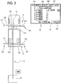
- FIG. 1 illustrates a preferred embodiment of a crane 10 for moving loads 13, in particular mounted on a respective movable transport vehicle, preferably in the form of a vehicle movable on the road, in particular the vehicle being in the form of a truck 11 which has a respective box for supporting the load 111 in which is positioned the crane 10.
- the crane 10 comprises an arm 12 for supporting the load 13 which is telescopically movable in a plurality of positions of extension included between a retracted position and a position of maximum extension and which comprises a plurality of sliding members 121.
- the supporting arm 12 is rotatable angularly, in particular horizontally, relative to a respective axis of rotation "P" of the crane 12 and it can be positioned in different angular positions of rotation, in particular situated along an angular range of extension of 360°.
- the crane 10 also comprising means 14 which are designed to stabilise the crane 12 to avoid the risk of overturning during the working operations of the arm 12, the stabilising means 14 being configurable in a plurality of stabilising configurations of the crane 12, as described in more detail below.
- each sliding member 121 is movable, in particular slidable, relative to the adjacent sliding member between a respective retracted position relative to the adjacent, or upstream, sliding member 121 and a respective extended position relative to the adjacent, or upstream, sliding member 121, for respectively extending and withdrawing the arm 12.
- the arm 12 for moving the load 13 can be positioned in respective inclined positions, in particular inclined with respect to a corresponding horizontal plane, between a maximum angular or inclined position, wherein the arm 12 can reach the maximum height for moving the load 13, and a minimum angular or inclined position, wherein the arm 12 can reach the minimum height for moving the load 13.
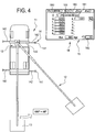
- the means 14 which are designed to stabilise the crane 12 to avoid the risk of overturning during the working operations of the arm 12 comprise one or more elements, or feet, for resting on the ground, 141, in particular in this embodiment there are four feet 141 resting on the ground which are each supported by the end of the rod of a respective jack preferably vertical 140 which can each be respectively positioned in a plurality of stabilising positions of the crane 12, between a respective position close to the crane 12, or to the vehicle 11 supporting the crane 12), and a position furthest away from the crane 12, or the vehicle 11 for supporting the crane 12.
- the elements, or feet, for resting on the ground, 141 which are supported at the end of the rod of respective vertical jacks 140, are supported by respective sliding members 142 which are movable, in particular transversely or horizontally, between a position retracted in a corresponding housing 143 fixed to the vehicle 11, and a maximum extension position wherein the sliding members 142 are outside the housing, in particular tubular, 143.
- the means 14 which are designed to stabilise the crane 12 are fixed, or extend, from the frame of the vehicle for supporting the crane, in particular laterally to the latter.
- the crane 10 there are means 18 which are designed to indicate, in particular to the user of the crane 10, the maximum load which can be lifted by the crane, that is to say, by the arm of the crane 10, as a function of the condition of extension of the arm 12 and/or the respective angular position of rotation of the arm 12.
- the means 18 for indicating the maximum load which can be lifted by the crane are in the form of means which display the maximum load which can be lifted.
- the indicator means 18 are provided at the means 16 for controlling the crane 12, in particular for controlling the load movement arm 12 of the crane 10.
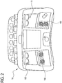
- control means of the crane 10, or of the arm 12 comprise a display unit 15 and respective manual control means, in particular in the form of pushbuttons and/or respective control levers 160, which can be suitably operated by the user.
- the display unit 15 of the means 16 for controlling the crane 12, in particular for controlling the load movement arm 12 of the crane 10, is designed to define the means 18 for indicating the maximum load which can be lifted.
- the means 16 for controlling the crane 12, in particular ther load movement arm 12 of the crane 10 are in the form of a remote control device, in particular portable, having a respective display unit 15.
- the means 18 which are designed to indicate to the user the maximum load which can be lifted by the crane 10, that is to say, by the arm 12 of the crane 10, indicate, in particular progressively, for the respective angular position of rotation 182, the maximum load which can be lifted as a function of the number of sliding members 121 of the arm 12 which are in the extended condition.
- the means 18 which are designed to indicate to the user the load which can be lifted by the crane 10, that is to say, the load which can be lifted by the arm 12 of the crane 10, provide, or comprise, a respective screen page, on a corresponding display unit 15 of the crane 12, the screen page comprising symbols 180 indicating the number of sliding members 121 which are in the extended condition or not; the symbols being in particular, as illustrated in Figures 3 to 5 , in the form of a sequence of natural numbers between the number zero and the number of the sliding members 121 of the respective arm 12 of the crane 10.
- the means 18 which are designed to indicate to the user the load which can be lifted by the crane 10, that is to say, the load which can be lifted by the arm (12) of the crane 10, provide a respective screen page, on a corresponding display unit 15 of the crane 12, the screen page comprising a plurality of zones 181, in particular situated at the symbols, in particular alongside the symbols 180, in which is indicated, or displayed, the respective value, for example, as illustrated, expressed in kilograms, of the maximum load which can be lifted by the crane 10, or by the arm 12 of the crane 10, in the corresponding working condition, that is, in the respective condition of extension of the arm 12 of the crane 10.
- the means 18 which are designed to indicate to the user the load which can be lifted by the crane 10, that is to say, the load which can be lifted by the arm 12 of the crane 10, provide a respective screen page, on a corresponding display unit 15 of the crane 12, the screen page comprising an area 182 in which is indicated, or displayed, the respective angular position of rotation for which are indicated, or displayed, the values of maximum load which can be lifted 181.
- the means for determining, or calculating, the maximum load which can be lifted by the crane 12, that is to say, by the arm 12 of the crane 10, as a function of the condition of extension of the arm 12 and/or the respective angular position of rotation of the arm 12, comprise respective means 22 which measure the specific configuration of the stabilising means 14 of the crane 12, in the respective working condition, in particular the configuration being defined by the respective condition or the extension position of the sliding members 142 for supporting the means 141 for resting on the ground of the stabilising means 14.
- the means 22 designed to measure the configuration of the stabilising means 14 comprise sensor means, which are not illustrated in detail in the accompanying drawings, which are designed to measure the length of extension of the sliding members 142 which carry the respective means 14 for resting on the ground.
- the means designed to indicate to the user the load which can be lifted by the crane 10, that is to say, by the arm 12 of the crane 10, comprise respective means 26, in particular including, or in the form of corresponding, software means or program instructions, which are designed to calculate the limit of stability point by point around the crane 10, in particular as a function of the configuration of the stabilising means 14 of the crane 12.
- the means designed to indicate to the user the load which can be lifted by the crane 10, that is to say, by the arm 12 of the crane 10, comprise respective means 28, in particular including, or in the form of corresponding, software means, which are designed to create a table which, for each angular position of rotation, associates with the respective number of sliding members 121 in the extended condition the relative maximum load value which can be lifted, in particular as a function of the configuration of the stabilising means 14 of the crane 12.
- the means which are designed to indicate to the user the load which can be lifted by the crane 10, that is to say, by the arm 12 of the crane 10, comprise respective means, in particular including or in the form of corresponding software means, which are designed to display, on the display unit 15, in particular of the crane, that is, in the respective area 181 of this, for the respective angular position of the arm indicated in the respective area 182, the value of maximum load which can be lifted that can be associated to the respective number of sliding members 121 in the extended condition, with the values of maximum load which can be lifted which are taken from the table created in the step 28.
Abstract
Description
- This invention relates to a crane for moving loads.
- The crane is, in particular, mounted on a respective movable transport vehicle, preferably in the form of a vehicle movable on the road, in particular the vehicle being in the form of a truck which has a respective box for supporting the load in which is positioned the crane.
- There are prior art cranes for moving loads which are mounted on a corresponding truck which has a respective box for supporting the load in which is positioned the crane.
- The prior art cranes comprise an arm for supporting the load which is telescopically movable in a plurality of positions of extension included between a retracted position and a position of maximum extension and which comprises a plurality of sliding members, and have the respective supporting arm which is rotatable angularly, in particular horizontally, relative to a respective axis of rotation of the crane and can therefore be positioned in different angular positions of rotation.
- The prior art cranes also comprise means which are designed to stabilise the crane to avoid the risk of overturning during the working operations of the arm, the stabilising means being configurable in a plurality of stabilising configurations of the crane.
- One problem seen in relation to these prior art cranes regards the fact that the user, whilst operating the crane, it is not able to know with certainty whether the operation is being performed in a dangerous condition or not. In fact, the manufacturers of these cranes usually provide the users with information regarding the maximum load which can be lifted by the crane, in the condition of maximum stability.
- Sometimes, however, it is necessary to operate in ambient conditions in which the condition of maximum stability is not achievable and in these cases the personnel cannot know whether the operation is being carried out safely or not.
- The need is therefor felt in the sector to provide a crane which allows the users to operate in a safe fashion.
- However, the need is felt in the sector to provide a crane which is particularly reliable.
- Moreover, the need is felt in the sector to provide a crane which allows users to operate in a particularly fast manner.
- The need is also felt in the sector to provide a crane which is easy to use. In addition, the need is felt in the sector to provide a crane which allows the user to foresee which manoeuvres can be performed safely.
- Some cranes are described in patent documents
US2017/036894 ,WO2017/135382 ,US4211332 ,US6170681 . - The present invention therefore proposes a new and/or alternative solution to the solutions known up to now and, more specifically, proposes to overcome one or more of the above mentioned drawbacks or problems and/or to meet one or more of the needs felt in the trade or inferable from the above.
- A crane is therefore provided for moving loads, in particular mounted on a respective movable transport vehicle, preferably in the form of a vehicle movable on the road, in particular the vehicle being in the form of a truck which has a respective box for supporting the load in which is positioned the crane; the crane comprising an arm for supporting the load which is telescopically movable in a plurality of positions of extension included between a retracted position and a position of maximum extension and which comprises a plurality of sliding members; the supporting arm being rotatable angularly, in particular horizontally, relative to a respective axis of rotation of the crane and it can be positioned in different angular positions of rotation; the crane also comprising means which are designed to stabilise the crane to avoid the risk of overturning during the working operations of the arm, the stabilising means being configurable in a plurality of stabilising configurations of the crane; characterised in that it comprises means which are designed to indicate, in particular to the user of the crane, the maximum load which can be lifted by the crane, that is to say, by the arm of the crane, as a function of the condition of extension of the arm and/or the respective angular position of rotation of the arm.
- In this way, it is possible to immediately inform the personnel regarding the operating capacity of the apparatus and it is therefore possible to operate in complete safety.
- This and other innovative aspects, or specific advantageous embodiments, are set out in the appended claims and its technical features are apparent from the detailed description which follows of a preferred, advantageous embodiment which must, however, be considered purely as a non-limiting example of the invention; the description being made with reference to the accompanying drawings, in which:
-
Figure 1 is a schematic side view of a preferred embodiment of the crane; -
Figure 2 is a schematic front elevation view of a remote control which can be used in the crane; -
Figures 3 to 5 illustrate respective schematic views which show different operational situations of the embodiment of the crane according to the invention; -
Figure 6 is a flow diagram of the preferred process, implemented by a respective software, to obtain the maximum load values which can be lifted. - The accompanying drawings illustrate a preferred embodiment of a
crane 10 for movingloads 13, in particular mounted on a respective movable transport vehicle, preferably in the form of a vehicle movable on the road, in particular the vehicle being in the form of atruck 11 which has a respective box for supporting theload 111 in which is positioned thecrane 10. - As may be inferred from the drawings, the
crane 10 comprises anarm 12 for supporting theload 13 which is telescopically movable in a plurality of positions of extension included between a retracted position and a position of maximum extension and which comprises a plurality of slidingmembers 121. - As may be inferred from the drawings, the supporting
arm 12 is rotatable angularly, in particular horizontally, relative to a respective axis of rotation "P" of thecrane 12 and it can be positioned in different angular positions of rotation, in particular situated along an angular range of extension of 360°. As may be inferred from the drawings, thecrane 10 also comprisingmeans 14 which are designed to stabilise thecrane 12 to avoid the risk of overturning during the working operations of thearm 12, the stabilising means 14 being configurable in a plurality of stabilising configurations of thecrane 12, as described in more detail below. - More specifically, as may be inferred from
Figure 1 , each slidingmember 121 is movable, in particular slidable, relative to the adjacent sliding member between a respective retracted position relative to the adjacent, or upstream, slidingmember 121 and a respective extended position relative to the adjacent, or upstream, slidingmember 121, for respectively extending and withdrawing thearm 12. - More specifically, moreover, the
arm 12 for moving theload 13 can be positioned in respective inclined positions, in particular inclined with respect to a corresponding horizontal plane, between a maximum angular or inclined position, wherein thearm 12 can reach the maximum height for moving theload 13, and a minimum angular or inclined position, wherein thearm 12 can reach the minimum height for moving theload 13. - More specifically, as may be inferred from the drawings, the
means 14 which are designed to stabilise thecrane 12 to avoid the risk of overturning during the working operations of thearm 12 comprise one or more elements, or feet, for resting on the ground, 141, in particular in this embodiment there are fourfeet 141 resting on the ground which are each supported by the end of the rod of a respective jack preferably vertical 140 which can each be respectively positioned in a plurality of stabilising positions of thecrane 12, between a respective position close to thecrane 12, or to thevehicle 11 supporting the crane 12), and a position furthest away from thecrane 12, or thevehicle 11 for supporting thecrane 12. - In effect, as illustrated, the elements, or feet, for resting on the ground, 141, which are supported at the end of the rod of respective
vertical jacks 140, are supported by respective slidingmembers 142 which are movable, in particular transversely or horizontally, between a position retracted in acorresponding housing 143 fixed to thevehicle 11, and a maximum extension position wherein the slidingmembers 142 are outside the housing, in particular tubular, 143. - As illustrated, the
means 14 which are designed to stabilise thecrane 12 are fixed, or extend, from the frame of the vehicle for supporting the crane, in particular laterally to the latter. - Advantageously, in the
crane 10 there aremeans 18 which are designed to indicate, in particular to the user of thecrane 10, the maximum load which can be lifted by the crane, that is to say, by the arm of thecrane 10, as a function of the condition of extension of thearm 12 and/or the respective angular position of rotation of thearm 12. - In this way, it is possible to immediately inform the personnel regarding the operating capacity of the apparatus and it is therefore possible to operate in complete safety.
- Advantageously, as may be inferred in particular from the drawing, the
means 18 for indicating the maximum load which can be lifted by the crane, that is to say, by the arm of the crane, are in the form of means which display the maximum load which can be lifted. - More specifically, as may be inferred in particular from
Figure 2 , there are means 16 for controlling thecrane 12, in particular thearm 12 for moving the load of thecrane 10. - Advantageously, as may be inferred from
Figures 2 to 5 , the indicator means 18 are provided at themeans 16 for controlling thecrane 12, in particular for controlling theload movement arm 12 of thecrane 10. - More specifically, as may be inferred from
Figure 2 , the control means of thecrane 10, or of thearm 12, comprise adisplay unit 15 and respective manual control means, in particular in the form of pushbuttons and/orrespective control levers 160, which can be suitably operated by the user. - Advantageously, as may be inferred from
Figures 3 to 5 , thedisplay unit 15 of themeans 16 for controlling thecrane 12, in particular for controlling theload movement arm 12 of thecrane 10, is designed to define themeans 18 for indicating the maximum load which can be lifted. Advantageously, as may be inferred fromFigure 2 , themeans 16 for controlling thecrane 12, in particular therload movement arm 12 of thecrane 10, are in the form of a remote control device, in particular portable, having arespective display unit 15. - Advantageously, as may be inferred from
Figures 3 to 5 , themeans 18 which are designed to indicate to the user the maximum load which can be lifted by thecrane 10, that is to say, by thearm 12 of thecrane 10, indicate, in particular progressively, for the respective angular position ofrotation 182, the maximum load which can be lifted as a function of the number of slidingmembers 121 of thearm 12 which are in the extended condition. - In this way, the user can immediately understand the current working condition and can understand the corresponding operating decisions. Advantageously, as may be inferred from
Figures 3 to 5 , themeans 18 which are designed to indicate to the user the load which can be lifted by thecrane 10, that is to say, the load which can be lifted by thearm 12 of thecrane 10, provide, or comprise, a respective screen page, on acorresponding display unit 15 of thecrane 12, the screenpage comprising symbols 180 indicating the number of slidingmembers 121 which are in the extended condition or not; the symbols being in particular, as illustrated inFigures 3 to 5 , in the form of a sequence of natural numbers between the number zero and the number of the slidingmembers 121 of therespective arm 12 of thecrane 10. - Advantageously, as may be inferred from
Figures 3 to 5 , themeans 18 which are designed to indicate to the user the load which can be lifted by thecrane 10, that is to say, the load which can be lifted by the arm (12) of thecrane 10, provide a respective screen page, on acorresponding display unit 15 of thecrane 12, the screen page comprising a plurality ofzones 181, in particular situated at the symbols, in particular alongside thesymbols 180, in which is indicated, or displayed, the respective value, for example, as illustrated, expressed in kilograms, of the maximum load which can be lifted by thecrane 10, or by thearm 12 of thecrane 10, in the corresponding working condition, that is, in the respective condition of extension of thearm 12 of thecrane 10. - Advantageously, as may be inferred from
Figures 3 to 5 , themeans 18 which are designed to indicate to the user the load which can be lifted by thecrane 10, that is to say, the load which can be lifted by thearm 12 of thecrane 10, provide a respective screen page, on acorresponding display unit 15 of thecrane 12, the screen page comprising anarea 182 in which is indicated, or displayed, the respective angular position of rotation for which are indicated, or displayed, the values of maximum load which can be lifted 181. - Advantageously, there are electronic processing means, not illustrated in detail in the accompanying drawings, implementing a corresponding process, through a respective program or software, which are designed to determine or calculate the maximum load which can be lifted by the
crane 12, that is to say, by thearm 12 of thecrane 10, as a function of the condition of extension of thearm 12 and/or the respective angular position of rotation of thearm 12. - Advantageously, as may be inferred in particular from
Figure 6 which illustrates a flow diagram of the process implemented by the crane, the means for determining, or calculating, the maximum load which can be lifted by thecrane 12, that is to say, by thearm 12 of thecrane 10, as a function of the condition of extension of thearm 12 and/or the respective angular position of rotation of thearm 12, compriserespective means 22 which measure the specific configuration of thestabilising means 14 of thecrane 12, in the respective working condition, in particular the configuration being defined by the respective condition or the extension position of the slidingmembers 142 for supporting themeans 141 for resting on the ground of thestabilising means 14. - Advantageously, the
means 22 designed to measure the configuration of thestabilising means 14 comprise sensor means, which are not illustrated in detail in the accompanying drawings, which are designed to measure the length of extension of the slidingmembers 142 which carry therespective means 14 for resting on the ground. - Advantageously, as may be inferred in particular from
Figure 6 , the means designed to indicate to the user the load which can be lifted by thecrane 10, that is to say, by thearm 12 of thecrane 10, compriserespective means 26, in particular including, or in the form of corresponding, software means or program instructions, which are designed to calculate the limit of stability point by point around thecrane 10, in particular as a function of the configuration of the stabilising means 14 of thecrane 12. Advantageously, as may be inferred in particular fromFigure 6 , the means designed to indicate to the user the load which can be lifted by thecrane 10, that is to say, by thearm 12 of thecrane 10, compriserespective means 28, in particular including, or in the form of corresponding, software means, which are designed to create a table which, for each angular position of rotation, associates with the respective number of slidingmembers 121 in the extended condition the relative maximum load value which can be lifted, in particular as a function of the configuration of the stabilising means 14 of thecrane 12. - Preferably, the means which are designed to indicate to the user the load which can be lifted by the
crane 10, that is to say, by thearm 12 of thecrane 10, comprise respective means, in particular including or in the form of corresponding software means, which are designed to display, on thedisplay unit 15, in particular of the crane, that is, in therespective area 181 of this, for the respective angular position of the arm indicated in therespective area 182, the value of maximum load which can be lifted that can be associated to the respective number of slidingmembers 121 in the extended condition, with the values of maximum load which can be lifted which are taken from the table created in thestep 28. - Advantageously, as may be inferred from
Figures 3 to 5 , the means for displaying in succession, on the display means 15 of thecrane 10, the values of maximum load which can be lifted by thecrane 10, in particular as a function of the number of slidingmembers 121 of thearm 12 which are in the extended condition, at respective angular positions ofrotation 182 of thearm 12, the displaying means comprising respective key means 165, in particular in the form of key means of theremote control unit 16, in particular which increase, for example by 10° degrees each time, the respective screens which display the respective values of maximum load which can be lifted by thecrane 10. - In this way, by progressively displaying the various screens which illustrate the maximum loads which can be lifted by the crane, in particular in the various positions of extension of the arm, along a respective angular range, if necessary along the entire angular arc of 360° around the crane, the user can immediately understand which actions may be undertaken to lift the load in a suitable manner.
- More specifically, as illustrated, there are means for activating the respective sliding
member 121 of thearm 12 of thecrane 10 relative to the adjacent sliding member between a respective retracted position relative to the latter and a respective extended position relative to the adjacent sliding member, in particular in the form of corresponding hydraulic drive means, in particular in the form of respective hydraulic jacks. - More specifically, as illustrated, although not illustrated in detail in the accompanying drawings, there are drive means for rotating the
telescopic arm 12 relative to the axis of rotation P perpendicular to thecrane 12. More specifically, as illustrated, although not illustrated in detail in the accompanying drawings, there are drive means for inclining thetelescopic arm 12 in respective inclined positions, in particular in the form of corresponding hydraulic drive means. - More specifically, as illustrated, although not illustrated in detail in the accompanying drawings, there are drive means for the sliding
members 142 which carry the stabilising means for resting on theground 141, in particular in the form of corresponding hydraulic drive means, preferably in the form of respective hydraulic jacks. - In practice, as is evident, the technical features described above allow the present invention, individually or in respective combination, to achieve one or more of the following advantageous results:
- it is possible to immediately inform the personnel regarding the operating capacity of the apparatus and it is therefore possible to operate in complete safety.
- the user can immediately understand the current working condition;
- a crane can be provided which is particularly reliable;
- a crane can be provided which makes it possible to operate in a particularly fast manner;
- a crane can be provided which is easy to use;
- a crane can be provided which allows the user to foresee which manoeuvres are to be performed.
- The invention described above is susceptible of industrial application. It would be obvious to one skilled in the art that several changes and modifications can be made to the invention without departing from the spirit and scope of the invention, described in depth above. It is also easy to imagine further embodiments of the invention comprising one or more of the features described herein. Moreover, it will be understood that all the details of the invention may be substituted for technically equivalent elements.
Claims (15)
- A crane (10) for moving loads (13), comprising an arm (12) for supporting the load (13) which is telescopically movable in a plurality of positions of extension included between a retracted position and a position of maximum extension and a plurality of sliding members (121); the supporting arm (12) being rotatable angularly, in particular horizontally, relative to a respective axis of rotation (P) of the crane (12) and it can be positioned in different angular positions of rotation; the crane (10) also comprising means (14) which are designed to stabilise the crane (12) to avoid the risk of overturning during the working operations of the arm (12), the stabilising means (14) being configurable in a plurality of stabilising configurations of the crane (12); wherein:- there are indicator means (18) which are designed to indicate, in particular to the user of the crane (10), the maximum load which can be lifted by the arm (12) of the crane (10), as a function of the condition of extension of the arm (12) and/or the respective angular position of rotation of the arm (12);wherein:- there are means (16) for controlling the load movement arm (12) of the crane (10);- the indicator means (18) are located at the control means (16) of the crane (12);- the indicator means (18) comprise a respective screen page, on a corresponding display unit (15) of the crane (12), the screen page comprising symbols (180) indicating the number of sliding members (121) which are in an extended condition;- the screen page comprises a plurality of zones (181), in particular situated at the symbols, in particular alongside the symbols (180), in which is indicated, or displayed, the respective value of the maximum load in the respective condition of extension of the arm (12) of the crane (10);- there are means for displaying in succession, on the display means (15) of the crane (10), the values of maximum load as a function of the number of sliding members (121) of the arm (12) which are in the extended condition, at respective angular positions of rotation (182) of the arm (12), the displaying means comprising respective key means (165);- the screen page comprising an area (182) in which is indicated, or displayed, the respective angular position of rotation for which are indicated, or displayed, the values of maximum load which can be lifted (181).
- The crane according to claim 1, wherein the means (18) for indicting the maximum load which can be lifted are in the form of means which display the maximum load which can be lifted.
- The crane according to any one of the preceding claims, wherein the control means of the crane (10) comprise a display unit (15) designed to define the indicator means (18) and comprise respective manual control means, in particular in the form of pushbuttons and/or respective control levers (160), which can be suitably operated by the user.
- The crane according to claim 3, wherein the control means (16) are in the form of a remote control device, in particular portable, having the display unit (15).
- The crane according to any one of the preceding claims, wherein the indicator means indicate, in particular progressively, for the respective angular position of rotation (182), the maximum load which can be lifted as a function of the number of sliding members (121) of the arm (12) which are in the extended condition.
- The crane according to any one of the preceding claims, wherein there are electronic processing means, implementing a corresponding program or software, which are designed to determine or calculate the maximum load as a function of the condition of extension of the arm (12) and/or the respective angular position of rotation of the arm (12).
- The crane according to claim 6, wherein the means which are designed to determine, or calculate, the maximum load comprise respective means (22) which measure the specific configuration of the stabilising means (14) of the crane (12), in the respective working condition, in particular the configuration being defined by the respective condition or the extension position of the sliding members (142) for supporting the means (141) for resting on the ground of the stabilising means (14).
- The crane according to claim 7, wherein the means (22) designed to measure the configuration of the stabilising means (14) comprise sensor means which are designed to measure the length of extension of the sliding members (142) which carry the respective means (14) for resting on the ground.
- The crane according to any one of the preceding claims, wherein:- the indicator means comprise respective software means or program instructions, which are designed to calculate the limit of stability point by point around the crane (10), as a function of the configuration of the means (14) for stabilising the crane (12);- the software means are designed to create a table which, for each angular position of rotation of the arm, associates with the respective number of sliding members (121) in the extended condition the relative maximum load value which can be lifted, in particular as a function of the configuration of the stabilising means (14) of the crane (12);- the stabilising means (14) comprise one or more elements, or feet, for resting on the ground, (141), which can each be respectively positioned in a plurality of stabilising positions of the crane (12), between a respective position close to the crane (12), or to the vehicle (11) supporting the crane (12), and a position furthest away from the crane (12), or the vehicle (11) for supporting the crane (12).
- The crane according to any one of the preceding claims, wherein the arm (12) for moving the load (13) can be positioned in respective inclined positions between a maximum angular or inclined position, wherein the arm (12) can reach the maximum height for moving the load (13), and a minimum angular or inclined position, wherein the arm (12) can reach the minimum height for moving the load (13).
- The crane according to any one of the preceding claims, wherein each sliding member (121) is movable, in particular slidable, relative to the adjacent sliding member between a respective retracted position relative to the adjacent sliding member (121) and a respective extended position relative to the adjacent sliding member (121), for respectively extending and withdrawing the arm (12).
- The crane according to any one of the preceding claims, wherein there are means for activating the respective sliding member (121) of the arm (12) of the crane (10) relative to the adjacent sliding member between a respective retracted position relative to the latter and a respective extended position relative to the same adjacent sliding member, in the form of respective hydraulic jacks.
- The crane according to any one of the preceding claims, wherein there are drive means for rotating the telescopic arm (12) relative to the axis of rotation (P) perpendicular to the crane (12).
- The crane according to any one of the preceding claims, wherein there are drive means for inclining the telescopic arm (12) in respective inclined positions, in the form of corresponding hydraulic drive means.
- The crane according to any one of the preceding claims, wherein there are drive means for the sliding members (142) which carry the stabilising means for resting on the ground (141), in the form of respective hydraulic jacks.
Applications Claiming Priority (1)
| Application Number | Priority Date | Filing Date | Title |
|---|---|---|---|
| IT201800001688A IT201800001688A1 (en) | 2018-01-23 | 2018-01-23 | TOWER CRANE |
Publications (2)
| Publication Number | Publication Date |
|---|---|
| EP3514101A1 true EP3514101A1 (en) | 2019-07-24 |
| EP3514101B1 EP3514101B1 (en) | 2021-03-17 |
Family
ID=62044837
Family Applications (1)
| Application Number | Title | Priority Date | Filing Date |
|---|---|---|---|
| EP19152992.4A Active EP3514101B1 (en) | 2018-01-23 | 2019-01-22 | Crane |
Country Status (3)
| Country | Link |
|---|---|
| EP (1) | EP3514101B1 (en) |
| DK (1) | DK3514101T3 (en) |
| IT (1) | IT201800001688A1 (en) |
Citations (4)
| Publication number | Priority date | Publication date | Assignee | Title |
|---|---|---|---|---|
| US4211332A (en) | 1978-04-03 | 1980-07-08 | R O Corporation | Color coded boom and chart system |
| US6170681B1 (en) | 1998-07-21 | 2001-01-09 | Kabushiki Kaisha Kobe Seiko Sho (Kobe Steel, Ltd.) Steel | Swing type machine and method for setting a safe work area and a rated load in same |
| US20170036894A1 (en) | 2014-04-22 | 2017-02-09 | Terex Global Gmbh | Method and Device for Operating a Mobile Crane and Mobile Crane |
| WO2017135382A1 (en) | 2016-02-03 | 2017-08-10 | 株式会社タダノ | Remote operation terminal, and system for remotely operating mobile crane |
-
2018
- 2018-01-23 IT IT201800001688A patent/IT201800001688A1/en unknown
-
2019
- 2019-01-22 EP EP19152992.4A patent/EP3514101B1/en active Active
- 2019-01-22 DK DK19152992.4T patent/DK3514101T3/en active
Patent Citations (4)
| Publication number | Priority date | Publication date | Assignee | Title |
|---|---|---|---|---|
| US4211332A (en) | 1978-04-03 | 1980-07-08 | R O Corporation | Color coded boom and chart system |
| US6170681B1 (en) | 1998-07-21 | 2001-01-09 | Kabushiki Kaisha Kobe Seiko Sho (Kobe Steel, Ltd.) Steel | Swing type machine and method for setting a safe work area and a rated load in same |
| US20170036894A1 (en) | 2014-04-22 | 2017-02-09 | Terex Global Gmbh | Method and Device for Operating a Mobile Crane and Mobile Crane |
| WO2017135382A1 (en) | 2016-02-03 | 2017-08-10 | 株式会社タダノ | Remote operation terminal, and system for remotely operating mobile crane |
Also Published As
| Publication number | Publication date |
|---|---|
| DK3514101T3 (en) | 2021-06-14 |
| EP3514101B1 (en) | 2021-03-17 |
| IT201800001688A1 (en) | 2019-07-23 |
Similar Documents
| Publication | Publication Date | Title |
|---|---|---|
| US7252203B2 (en) | Mobile crane having a superlift device | |
| US10144621B2 (en) | Method and device for operating a mobile crane and mobile crane | |
| EP2616382B3 (en) | Controller for use with a machine, machine including said controller, and method for controlling a machine. | |
| US7004285B2 (en) | Load-sensing mechanism for aerial work apparatus | |
| JP6161776B1 (en) | Crane work auxiliary device | |
| US9957141B2 (en) | Method for determining the load capacity of cranes | |
| JP6594559B2 (en) | Device comprising a control unit and a mobile control module | |
| JP6624173B2 (en) | Overload prevention device | |
| US10336588B2 (en) | Mobile crane | |
| US6779961B2 (en) | Material handler with electronic load chart | |
| EP3514101B1 (en) | Crane | |
| JP2010159148A (en) | Jack reaction display device of work vehicle and work vehicle | |
| JP2773854B2 (en) | Work display device for work vehicles | |
| KR101038523B1 (en) | Working radius of crane vehicle control device | |
| JP2016179869A (en) | Adjusting device of work machine | |
| US10913643B1 (en) | Dual boom load monitoring | |
| CN207903797U (en) | A kind of packaged type cantilever device for hoisting | |
| JP2016113218A (en) | Dynamic lift off assist device | |
| EP4077198A1 (en) | System and method for monitoring crane and crane having the same | |
| US20190241407A1 (en) | Suspended load calculation device | |
| US20230227300A1 (en) | Machine stability detection and indication for mobile lifting equipment | |
| JPH10258991A (en) | Crane cargo operation display | |
| JPH0373795A (en) | Operation state display device in self traveling type crane | |
| WO2017170381A1 (en) | Display system for work vehicle | |
| JPH0781886A (en) | Display device for movable range of crane |
Legal Events
| Date | Code | Title | Description |
|---|---|---|---|
| PUAI | Public reference made under article 153(3) epc to a published international application that has entered the european phase |
Free format text: ORIGINAL CODE: 0009012 |
|
| STAA | Information on the status of an ep patent application or granted ep patent |
Free format text: STATUS: THE APPLICATION HAS BEEN PUBLISHED |
|
| AK | Designated contracting states |
Kind code of ref document: A1 Designated state(s): AL AT BE BG CH CY CZ DE DK EE ES FI FR GB GR HR HU IE IS IT LI LT LU LV MC MK MT NL NO PL PT RO RS SE SI SK SM TR |
|
| AX | Request for extension of the european patent |
Extension state: BA ME |
|
| STAA | Information on the status of an ep patent application or granted ep patent |
Free format text: STATUS: REQUEST FOR EXAMINATION WAS MADE |
|
| 17P | Request for examination filed |
Effective date: 20190927 |
|
| RBV | Designated contracting states (corrected) |
Designated state(s): AL AT BE BG CH CY CZ DE DK EE ES FI FR GB GR HR HU IE IS IT LI LT LU LV MC MK MT NL NO PL PT RO RS SE SI SK SM TR |
|
| STAA | Information on the status of an ep patent application or granted ep patent |
Free format text: STATUS: EXAMINATION IS IN PROGRESS |
|
| 17Q | First examination report despatched |
Effective date: 20200312 |
|
| GRAP | Despatch of communication of intention to grant a patent |
Free format text: ORIGINAL CODE: EPIDOSNIGR1 |
|
| STAA | Information on the status of an ep patent application or granted ep patent |
Free format text: STATUS: GRANT OF PATENT IS INTENDED |
|
| INTG | Intention to grant announced |
Effective date: 20201002 |
|
| RAP1 | Party data changed (applicant data changed or rights of an application transferred) |
Owner name: EFFER S.P.A. |
|
| GRAS | Grant fee paid |
Free format text: ORIGINAL CODE: EPIDOSNIGR3 |
|
| GRAA | (expected) grant |
Free format text: ORIGINAL CODE: 0009210 |
|
| STAA | Information on the status of an ep patent application or granted ep patent |
Free format text: STATUS: THE PATENT HAS BEEN GRANTED |
|
| AK | Designated contracting states |
Kind code of ref document: B1 Designated state(s): AL AT BE BG CH CY CZ DE DK EE ES FI FR GB GR HR HU IE IS IT LI LT LU LV MC MK MT NL NO PL PT RO RS SE SI SK SM TR |
|
| REG | Reference to a national code |
Ref country code: GB Ref legal event code: FG4D |
|
| REG | Reference to a national code |
Ref country code: CH Ref legal event code: EP |
|
| REG | Reference to a national code |
Ref country code: DE Ref legal event code: R096 Ref document number: 602019003145 Country of ref document: DE |
|
| REG | Reference to a national code |
Ref country code: IE Ref legal event code: FG4D |
|
| REG | Reference to a national code |
Ref country code: AT Ref legal event code: REF Ref document number: 1372072 Country of ref document: AT Kind code of ref document: T Effective date: 20210415 |
|
| REG | Reference to a national code |
Ref country code: DK Ref legal event code: T3 Effective date: 20210608 |
|
| RAP4 | Party data changed (patent owner data changed or rights of a patent transferred) |
Owner name: EFFER S.R.L. |
|
| REG | Reference to a national code |
Ref country code: LT Ref legal event code: MG9D |
|
| PG25 | Lapsed in a contracting state [announced via postgrant information from national office to epo] |
Ref country code: NO Free format text: LAPSE BECAUSE OF FAILURE TO SUBMIT A TRANSLATION OF THE DESCRIPTION OR TO PAY THE FEE WITHIN THE PRESCRIBED TIME-LIMIT Effective date: 20210617 Ref country code: BG Free format text: LAPSE BECAUSE OF FAILURE TO SUBMIT A TRANSLATION OF THE DESCRIPTION OR TO PAY THE FEE WITHIN THE PRESCRIBED TIME-LIMIT Effective date: 20210617 Ref country code: FI Free format text: LAPSE BECAUSE OF FAILURE TO SUBMIT A TRANSLATION OF THE DESCRIPTION OR TO PAY THE FEE WITHIN THE PRESCRIBED TIME-LIMIT Effective date: 20210317 Ref country code: GR Free format text: LAPSE BECAUSE OF FAILURE TO SUBMIT A TRANSLATION OF THE DESCRIPTION OR TO PAY THE FEE WITHIN THE PRESCRIBED TIME-LIMIT Effective date: 20210618 Ref country code: HR Free format text: LAPSE BECAUSE OF FAILURE TO SUBMIT A TRANSLATION OF THE DESCRIPTION OR TO PAY THE FEE WITHIN THE PRESCRIBED TIME-LIMIT Effective date: 20210317 |
|
| REG | Reference to a national code |
Ref country code: NL Ref legal event code: MP Effective date: 20210317 |
|
| PG25 | Lapsed in a contracting state [announced via postgrant information from national office to epo] |
Ref country code: SE Free format text: LAPSE BECAUSE OF FAILURE TO SUBMIT A TRANSLATION OF THE DESCRIPTION OR TO PAY THE FEE WITHIN THE PRESCRIBED TIME-LIMIT Effective date: 20210317 Ref country code: RS Free format text: LAPSE BECAUSE OF FAILURE TO SUBMIT A TRANSLATION OF THE DESCRIPTION OR TO PAY THE FEE WITHIN THE PRESCRIBED TIME-LIMIT Effective date: 20210317 Ref country code: LV Free format text: LAPSE BECAUSE OF FAILURE TO SUBMIT A TRANSLATION OF THE DESCRIPTION OR TO PAY THE FEE WITHIN THE PRESCRIBED TIME-LIMIT Effective date: 20210317 |
|
| PG25 | Lapsed in a contracting state [announced via postgrant information from national office to epo] |
Ref country code: NL Free format text: LAPSE BECAUSE OF FAILURE TO SUBMIT A TRANSLATION OF THE DESCRIPTION OR TO PAY THE FEE WITHIN THE PRESCRIBED TIME-LIMIT Effective date: 20210317 |
|
| REG | Reference to a national code |
Ref country code: AT Ref legal event code: PC Ref document number: 1372072 Country of ref document: AT Kind code of ref document: T Owner name: EFFER S.R.L., IT Effective date: 20210824 |
|
| PG25 | Lapsed in a contracting state [announced via postgrant information from national office to epo] |
Ref country code: LT Free format text: LAPSE BECAUSE OF FAILURE TO SUBMIT A TRANSLATION OF THE DESCRIPTION OR TO PAY THE FEE WITHIN THE PRESCRIBED TIME-LIMIT Effective date: 20210317 Ref country code: CZ Free format text: LAPSE BECAUSE OF FAILURE TO SUBMIT A TRANSLATION OF THE DESCRIPTION OR TO PAY THE FEE WITHIN THE PRESCRIBED TIME-LIMIT Effective date: 20210317 Ref country code: EE Free format text: LAPSE BECAUSE OF FAILURE TO SUBMIT A TRANSLATION OF THE DESCRIPTION OR TO PAY THE FEE WITHIN THE PRESCRIBED TIME-LIMIT Effective date: 20210317 Ref country code: SM Free format text: LAPSE BECAUSE OF FAILURE TO SUBMIT A TRANSLATION OF THE DESCRIPTION OR TO PAY THE FEE WITHIN THE PRESCRIBED TIME-LIMIT Effective date: 20210317 |
|
| PG25 | Lapsed in a contracting state [announced via postgrant information from national office to epo] |
Ref country code: SK Free format text: LAPSE BECAUSE OF FAILURE TO SUBMIT A TRANSLATION OF THE DESCRIPTION OR TO PAY THE FEE WITHIN THE PRESCRIBED TIME-LIMIT Effective date: 20210317 Ref country code: RO Free format text: LAPSE BECAUSE OF FAILURE TO SUBMIT A TRANSLATION OF THE DESCRIPTION OR TO PAY THE FEE WITHIN THE PRESCRIBED TIME-LIMIT Effective date: 20210317 Ref country code: PT Free format text: LAPSE BECAUSE OF FAILURE TO SUBMIT A TRANSLATION OF THE DESCRIPTION OR TO PAY THE FEE WITHIN THE PRESCRIBED TIME-LIMIT Effective date: 20210719 Ref country code: PL Free format text: LAPSE BECAUSE OF FAILURE TO SUBMIT A TRANSLATION OF THE DESCRIPTION OR TO PAY THE FEE WITHIN THE PRESCRIBED TIME-LIMIT Effective date: 20210317 Ref country code: IS Free format text: LAPSE BECAUSE OF FAILURE TO SUBMIT A TRANSLATION OF THE DESCRIPTION OR TO PAY THE FEE WITHIN THE PRESCRIBED TIME-LIMIT Effective date: 20210717 |
|
| REG | Reference to a national code |
Ref country code: DE Ref legal event code: R097 Ref document number: 602019003145 Country of ref document: DE |
|
| PLBE | No opposition filed within time limit |
Free format text: ORIGINAL CODE: 0009261 |
|
| STAA | Information on the status of an ep patent application or granted ep patent |
Free format text: STATUS: NO OPPOSITION FILED WITHIN TIME LIMIT |
|
| PG25 | Lapsed in a contracting state [announced via postgrant information from national office to epo] |
Ref country code: AL Free format text: LAPSE BECAUSE OF FAILURE TO SUBMIT A TRANSLATION OF THE DESCRIPTION OR TO PAY THE FEE WITHIN THE PRESCRIBED TIME-LIMIT Effective date: 20210317 Ref country code: ES Free format text: LAPSE BECAUSE OF FAILURE TO SUBMIT A TRANSLATION OF THE DESCRIPTION OR TO PAY THE FEE WITHIN THE PRESCRIBED TIME-LIMIT Effective date: 20210317 |
|
| 26N | No opposition filed |
Effective date: 20211220 |
|
| PG25 | Lapsed in a contracting state [announced via postgrant information from national office to epo] |
Ref country code: SI Free format text: LAPSE BECAUSE OF FAILURE TO SUBMIT A TRANSLATION OF THE DESCRIPTION OR TO PAY THE FEE WITHIN THE PRESCRIBED TIME-LIMIT Effective date: 20210317 |
|
| PG25 | Lapsed in a contracting state [announced via postgrant information from national office to epo] |
Ref country code: IS Free format text: LAPSE BECAUSE OF FAILURE TO SUBMIT A TRANSLATION OF THE DESCRIPTION OR TO PAY THE FEE WITHIN THE PRESCRIBED TIME-LIMIT Effective date: 20210717 |
|
| PGFP | Annual fee paid to national office [announced via postgrant information from national office to epo] |
Ref country code: FR Payment date: 20220126 Year of fee payment: 4 |
|
| REG | Reference to a national code |
Ref country code: DE Ref legal event code: R081 Ref document number: 602019003145 Country of ref document: DE Owner name: HIAB AB, SE Free format text: FORMER OWNER: EFFER S.P.A., MINERBIO, IT |
|
| REG | Reference to a national code |
Ref country code: GB Ref legal event code: 732E Free format text: REGISTERED BETWEEN 20220714 AND 20220720 |
|
| PG25 | Lapsed in a contracting state [announced via postgrant information from national office to epo] |
Ref country code: MC Free format text: LAPSE BECAUSE OF FAILURE TO SUBMIT A TRANSLATION OF THE DESCRIPTION OR TO PAY THE FEE WITHIN THE PRESCRIBED TIME-LIMIT Effective date: 20210317 |
|
| REG | Reference to a national code |
Ref country code: CH Ref legal event code: PL |
|
| REG | Reference to a national code |
Ref country code: BE Ref legal event code: MM Effective date: 20220131 |
|
| PG25 | Lapsed in a contracting state [announced via postgrant information from national office to epo] |
Ref country code: LU Free format text: LAPSE BECAUSE OF NON-PAYMENT OF DUE FEES Effective date: 20220122 |
|
| PG25 | Lapsed in a contracting state [announced via postgrant information from national office to epo] |
Ref country code: BE Free format text: LAPSE BECAUSE OF NON-PAYMENT OF DUE FEES Effective date: 20220131 |
|
| REG | Reference to a national code |
Ref country code: AT Ref legal event code: PC Ref document number: 1372072 Country of ref document: AT Kind code of ref document: T Owner name: HIAB AB, SE Effective date: 20221018 |
|
| PG25 | Lapsed in a contracting state [announced via postgrant information from national office to epo] |
Ref country code: LI Free format text: LAPSE BECAUSE OF NON-PAYMENT OF DUE FEES Effective date: 20220131 Ref country code: CH Free format text: LAPSE BECAUSE OF NON-PAYMENT OF DUE FEES Effective date: 20220131 |
|
| PG25 | Lapsed in a contracting state [announced via postgrant information from national office to epo] |
Ref country code: IE Free format text: LAPSE BECAUSE OF NON-PAYMENT OF DUE FEES Effective date: 20220122 |
|
| PGFP | Annual fee paid to national office [announced via postgrant information from national office to epo] |
Ref country code: DK Payment date: 20230126 Year of fee payment: 5 |
|
| PGFP | Annual fee paid to national office [announced via postgrant information from national office to epo] |
Ref country code: IT Payment date: 20230120 Year of fee payment: 5 Ref country code: DE Payment date: 20230127 Year of fee payment: 5 |
|
| REG | Reference to a national code |
Ref country code: AT Ref legal event code: UEP Ref document number: 1372072 Country of ref document: AT Kind code of ref document: T Effective date: 20210317 |
|
| GBPC | Gb: european patent ceased through non-payment of renewal fee |
Effective date: 20230122 |
|
| PG25 | Lapsed in a contracting state [announced via postgrant information from national office to epo] |
Ref country code: GB Free format text: LAPSE BECAUSE OF NON-PAYMENT OF DUE FEES Effective date: 20230122 |
|
| PG25 | Lapsed in a contracting state [announced via postgrant information from national office to epo] |
Ref country code: FR Free format text: LAPSE BECAUSE OF NON-PAYMENT OF DUE FEES Effective date: 20230131 |