EP3513707B1 - Vorrichtung für optische kohärenztomografie - Google Patents
Vorrichtung für optische kohärenztomografie Download PDFInfo
- Publication number
- EP3513707B1 EP3513707B1 EP19152797.7A EP19152797A EP3513707B1 EP 3513707 B1 EP3513707 B1 EP 3513707B1 EP 19152797 A EP19152797 A EP 19152797A EP 3513707 B1 EP3513707 B1 EP 3513707B1
- Authority
- EP
- European Patent Office
- Prior art keywords
- entropy
- light
- interference signals
- generated
- interference
- Prior art date
- Legal status (The legal status is an assumption and is not a legal conclusion. Google has not performed a legal analysis and makes no representation as to the accuracy of the status listed.)
- Active
Links
Images


Classifications
-
- A—HUMAN NECESSITIES
- A61—MEDICAL OR VETERINARY SCIENCE; HYGIENE
- A61B—DIAGNOSIS; SURGERY; IDENTIFICATION
- A61B3/00—Apparatus for testing the eyes; Instruments for examining the eyes
- A61B3/10—Objective types, i.e. instruments for examining the eyes independent of the patients' perceptions or reactions
- A61B3/12—Objective types, i.e. instruments for examining the eyes independent of the patients' perceptions or reactions for looking at the eye fundus, e.g. ophthalmoscopes
- A61B3/1225—Objective types, i.e. instruments for examining the eyes independent of the patients' perceptions or reactions for looking at the eye fundus, e.g. ophthalmoscopes using coherent radiation
- A61B3/1233—Objective types, i.e. instruments for examining the eyes independent of the patients' perceptions or reactions for looking at the eye fundus, e.g. ophthalmoscopes using coherent radiation for measuring blood flow, e.g. at the retina
-
- A—HUMAN NECESSITIES
- A61—MEDICAL OR VETERINARY SCIENCE; HYGIENE
- A61B—DIAGNOSIS; SURGERY; IDENTIFICATION
- A61B3/00—Apparatus for testing the eyes; Instruments for examining the eyes
- A61B3/10—Objective types, i.e. instruments for examining the eyes independent of the patients' perceptions or reactions
- A61B3/102—Objective types, i.e. instruments for examining the eyes independent of the patients' perceptions or reactions for optical coherence tomography [OCT]
-
- A—HUMAN NECESSITIES
- A61—MEDICAL OR VETERINARY SCIENCE; HYGIENE
- A61B—DIAGNOSIS; SURGERY; IDENTIFICATION
- A61B5/00—Measuring for diagnostic purposes; Identification of persons
- A61B5/0059—Measuring for diagnostic purposes; Identification of persons using light, e.g. diagnosis by transillumination, diascopy, fluorescence
- A61B5/0062—Arrangements for scanning
- A61B5/0066—Optical coherence imaging
-
- G—PHYSICS
- G01—MEASURING; TESTING
- G01B—MEASURING LENGTH, THICKNESS OR SIMILAR LINEAR DIMENSIONS; MEASURING ANGLES; MEASURING AREAS; MEASURING IRREGULARITIES OF SURFACES OR CONTOURS
- G01B9/00—Measuring instruments characterised by the use of optical techniques
- G01B9/02—Interferometers
- G01B9/0209—Low-coherence interferometers
- G01B9/02091—Tomographic interferometers, e.g. based on optical coherence
Definitions
- the technique disclosed herein relates to an optical coherence tomographic device.
- a dynamic part in a scattering sample such as a position of a blood vessel in a living organism
- fluorescence imaging that is employed in a wide variety of clinical uses nowadays is known as a method for specifying a dynamic part in a scattering sample.
- a dynamic part in a scattering sample is specified by injecting a contrast medium containing fluorochrome into a patient's body and detecting fluorescence exhibited by the fluorochrome.
- OCT optical coherence tomography
- US 2014/0334707 A1 discloses the features of the preamble of claim 1 and describes an eye tracking method for determining a position of an eye or a part of an eye in an image of an image sequence by performing a comparison between said image and a reference image.
- WO 2014/085911 A1 describes various embodiments of systems and methods for obtaining wide filed OCT images and other types of image data from at least one portion of a sample.
- EP 3 278 720 A1 describes an optical coherence tomographic device, which is configured to acquire a tomographic image of a subject by using an optical interferometry.
- the contrast medium needs to be injected into the patient's body, and thus there was a problem that patient's affliction is grave. Further, in a method using OCT as described in US Patent Application Publication No. 2016/0066798 , there was a problem that the dynamic part in the scattering sample cannot be specified with high accuracy.
- the disclosure herein discloses a technique that detects a dynamic part in a scattering sample noninvasively and with high accuracy.
- An optical coherence tomographic device comprises: a light source; a measurement light generator configured to generate measurement light by using light from the light source and to generate reflected light from a target region in a scattering sample by irradiating the target region with the measurement light, the target region comprising a blood vessel; a reference light generator configured to generate reference light by using the light from the light source; an interference light generator configured to generate interference light by combining the reflected light from the target region generated in the measurement light generator and the reference light generated in the reference light generator; an interference light detector configured to detect the interference light generated in the interference light generator and to generate interference signals by converting the interference light; a processor; and a memory storing computer-readable instructions therein, the computer-readable instructions, when executed by the processor, causing the optical coherence tomographic device to execute: acquiring a plurality of tomographic images for a same cross section in the target region in time series from the interference signals generated in the interference light detector; calculating an entropy of the generated interference signals based on
- the plurality of tomographic images is acquired for the same cross section in the specific target region in time series, by which the entropy of the acquired interference signals can be calculated.
- Tomographic images hardly change over time at a stationary part in the scattering sample, whereas the tomographic images change over time at a dynamic part in the scattering sample. Due to this, from a time-series perspective, the entropy is low at the stationary part such as a tissue that hardly moves in the scattering sample, and it is high at the dynamic part such as a blood vessel. Due to this, the dynamic part can be specified noninvasively and with high accuracy by calculating the entropy of the interference signals.
- the computer-readable instructions when executed by the processor, may further cause the optical coherence tomographic device to execute: calculating an entropy of noise component in the generated interference signals based on the plurality of tomographic images acquired in time series; and correcting the entropy of the generated interference signals by subtracting the entropy of noise component from the entropy of the generated interference signals.
- the entropy of the generated interference signals includes the entropy of the noise component.
- randomness (entropy) which authentic interference signals possess is statistically not correlated with randomness (entropy) caused by the noise component.
- the entropy of the generated interference signals is a sum of the entropy which the authentic interference signals possess and the entropy of the noise component. Therefore, according to the invention, the entropy of the authentic interference signals is calculated by calculating the entropy of the noise component and subtracting this from the entropy of the generated interference signals. By doing so, the entropy of the interference signals is accurately calculated, and a dynamic part is more accurately specified.
- the computer-readable instructions when executed by the processor, may further cause the optical coherence tomographic device to execute: acquiring a plurality of tomographic images for each of a plurality of cross sections in the target region in time series; and generating specified tomographic images respectively for the plurality of cross sections by executing the calculating of the entropy of the generated interference signals and the specifying of the dynamic part to each of the plurality of cross sections, each of the specified tomographic images specifying the dynamic part in corresponding one of the plurality of cross sections.
- the target region can be grasped three-dimensionally. Due to this, an examiner can more accurately grasp the dynamic part of the target region.
- the computer-readable instructions when executed by the processor, may further cause the optical coherence tomographic device to execute: generating a front image of the target region by using three-dimensional image data obtained by superimposing the specified tomographic images. According to such a configuration, a two-dimensional front image is generated for the target region for which the dynamic part has been specified. Due to this, the examiner can more easily grasp the dynamic part in the target region.
- the optical coherence tomographic device includes an interference optical system 10 configured to cause reflected light reflected from a subject eye E and reference light to interfere with each other, an observation optical system 42 configured to observe an anterior part of the subject eye E, an alignment optical system (not shown) configured to align the optical coherence tomographic device in a predetermined positional relationship with the subject eye E, and a K-clock generator 56 (shown in FIG. 2 ) configured to generate K-clock signals. Since a configuration in a known ophthalmology device may be used as the alignment optical system, a detailed description thereof will be omitted.
- the interference optical system 10 includes a light source 12, a measurement optical system configured to irradiate inside of the subject eye E with light from the light source 12 and generate reflected light therefrom, a reference optical system configured to generate reference light from the light of the light source 12, and a balance detector 38 configured to detect interference light that is a combination of the reflected light guided by the measurement optical system and the reference light guided by the reference optical system.
- the light source 12 is a wavelength-sweeping light source, and is configured to change a waveform of the light emitted therefrom at a predetermined cycle.
- a reflected position of reflected light that interferes with the reference light, among reflected light from respective parts of the subject eye E in a depth direction changes in the depth direction of the subject eye E in accordance with the wavelength of the emitted light. Due to this, it is possible to specify positions of the respective parts (such as a crystalline lens and a retina) inside the subject eye E by measuring the interference light while changing the wavelength of the emitted light.
- the measurement optical system includes fiber couplers 16, 36, a collimator lens 18, a focus lens 20, a Galvano mirror 22, a lens 24, a dichroic mirror 26, and an object lens 28.
- Light outputted from the light source 12 is inputted to the fiber coupler 16 through an optical fiber.
- the light inputted to the fiber coupler 16 is split into measurement light and reference light in the fiber coupler 16 and they are outputted therefrom.
- the measurement light outputted from the fiber coupler 16 is inputted to the collimator lens 18 through an optical fiber.
- the measurement light outputted to the collimator lens 18 enters the subject eye E through the focus lens 20, the Galvano mirror 22, the lens 24, the dichroic mirror 26, and the object lens 28.
- Reflected light from the subject eye E is inputted to the collimator lens 18 through the object lens 28, the dichroic mirror 26, the lens 24, the Galvano mirror 22, and the focus lens 20, in an opposite direction from the above.
- the reflected light inputted to the collimator lens 18 is inputted to the fiber coupler 16 through the optical fiber.
- the reflected light inputted to the fiber coupler 16 is inputted to one of inputs of the fiber coupler 36 through an optical fiber.
- the measurement optical system includes a second driver 48 (shown in FIG. 2 ) configured to move the focus lens 20 forward and backward in an optical axis direction, and a third driver 50 (shown in FIG. 2 ) configured to tilt the Galvano mirror 22 with respect to an optical axis.
- a position of a focal point of the light entering the subject eye E changes in the depth direction of the subject eye E by the second driver 48 moving the focus lens 20 in a direction of an arrow A in FIG. 1 .
- an irradiation position of the measurement light to the subject eye E is scanned by the third driver 50 tilting the Galvano mirror 22.
- the reference optical system includes the fiber coupler 16, collimator lenses 30, 34, a prism 32, and the fiber coupler 36.
- the reference light outputted from the fiber coupler 16 is inputted to the collimator lens 30 through an optical fiber.
- the reference light inputted to the collimator lens 30 is reflected at the prism 32, and then is outputted to the collimator lens 34.
- the reference light inputted to the collimator lens 34 is inputted to another one of the inputs of the fiber coupler 36 through an optical fiber.
- the reference optical system includes a fourth driver 52 (shown in FIG. 2 ) configured to move the prism 32 forward and backward with respect to the collimator lenses 30, 34.
- An optical path length of the reference optical system changes by the fourth driver 52 moving the prism 32 in a direction of an arrow B in FIG. 1 . Due to this, the optical path length of the reference optical system can be adjusted to substantially match an optical path length of the measurement optical system.
- the fiber coupler 36 is configured to combine the reflected light from the subject eye E and the reference light that were inputted thereto to generate interference light.
- the fiber coupler 36 is further configured to split the generated interference light into two interference light having phases that differ by 180 degrees from each other, and input them to the balance detector 38.
- the balance detector 38 is configured to execute a process for differential amplification and a process for reducing noise on the two interference light having the phases that differ by 180 degrees, which are inputted from the fiber coupler 36, to convert them into electric signals (interference signals).
- the balance detector 38 is configured to output the generated interference signals to an AD converter 40.
- the AD converter 40 is configured to execute A/D conversion on the inputted interference signals, and sample them as digital signals. The sampled interference signals are outputted to a processor 60.
- the K-clock generator 56 (shown in FIG. 2 ) is configured to optically generate sample clock (K-clock) signals from the light of the light source 12 to sample the interference signals at a regular interval frequency (frequency interval that is equalized with respect to light frequency). Further, the generated K-clock signals are outputted toward the processor 60. Due to this, the processor 60 samples the interference signals based on the K-clock signals, by which distortion in the interference signals can be suppressed and deterioration in resolution can be prevented. In the present embodiment, the interference signals that were sampled at timings defined by the K-clock signals are inputted to the processor 60, however, no limitation is placed to this configuration. For example, the processor 60 may execute a process to scale data sampled at a predetermined time interval by using a function indicating a frequency with respect to a preset sweep time, or a sweep profile that is acquired simultaneously therewith.
- the observation optical system 42 is configured to irradiate the subject eye E with observation light via the dichroic mirror 26, and captures reflected light reflected from the subject eye E (that is, reflected light of the irradiated observation light).
- the dichroic mirror 26 allows the light from the light source 12 of the interference optical system 10 pass therethrough, while it reflects the light from a light source of the observation optical system 42. Due to this, in the optical coherence tomographic device according to the present embodiment, the measurement by the interference optical system 10 and the observation of the anterior part by the observation optical system 42 can be carried out simultaneously. Since a configuration used in a known optical coherence tomographic device can be used as the observation optical system 42, a description of its detailed configuration will be omitted.
- the optical coherence tomographic device may be provided with a vision fixation target optical system configured to lead vision fixation of the subject to facilitate the measurement, and may be provided with a SLO optical system configured to acquire a planar image of a fundus of the subject eye E.
- the optical coherence tomographic device includes a position adjusting mechanism 44 (shown in FIG. 2 ) configured to adjust a position of the optical coherence tomographic device with respect to the subject eye E, and a first driver 46 (shown in FIG. 2 ) configured to drive this position adjusting mechanism 44.
- a position adjusting mechanism 44 shown in FIG. 2
- a first driver 46 shown in FIG. 2
- a process to adjust the position by the position adjusting mechanism 44 will be described later.
- the optical coherence tomographic device is controlled by the processor 60.
- the processor 60 includes a microcomputer (microprocessor) constituted of CPU, ROM, RAM, and the like.
- the processor 60 is connected to the light source 12, the first to fourth drivers 46 to 52, a monitor 54, and the observation optical system 42.
- the processor 60 is configured to control on/off of the light source 12, and drive the respective units 42, 20, 22, 32 by controlling the first to fourth drivers 46 to 52.
- the processor 60 is configured to control the observation optical system 42 to display an image of the anterior part captured by the observation optical system 42 on the monitor 54.
- the processor 60 is also connected to the AD converter 40 and the K-clock generator 56.
- the K-clock signals from the K-clock generator 56 are inputted to the processor 60, and the interference signals sampled at the timings according to the K-clock signals are inputted to the processor 60 from the AD converter 40.
- the processor 60 executes calculation processes, such as a Fourier transform process, on the interference signals from the AD converter 40 to generate tomographic images. Data inputted to the processor 60 and calculation results thereof are stored in a memory (not shown).
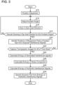
- FIG. 3 is a flowchart showing an example of the process to specify a dynamic part of the subject eye E by using the optical coherence tomographic device according to the present embodiment.
- steps S12 to S22 are processes to capture a plurality of tomographic images for a same cross section of the subject eye E in time series
- steps S24 to S30 are processes to specify a dynamic part in the scattering sample from the acquired tomographic images.
- the examiner operates an operation member, such as a joystick which is not shown, to position the optical coherence tomographic device with respect to the subject eye E (S12). That is, the processor 60 drives the position adjusting mechanism 44 by controlling the first driver 46 according to the examiner's operation on the operation member. Due to this, positions of the optical coherence tomographic device with respect to the subject eye E in xy directions (vertical and horizontal directions) and in a z direction (a direction along which the optical coherence tomographic device moves forward/backward with respect to the subject eye E) are adjusted. Further, the processor 60 drives the second driver 48 to adjust a position of the focus lens 20, and drives the fourth driver 52 to adjust a position of the prism 32.
- an operation member such as a joystick which is not shown
- the position of the focal point of the light entering the subject eye E from the light source 12 is set to a predetermined position in the subject eye E (such as an anterior surface of the cornea), and a zero-point position where the optical path length of the measurement optical system matches the optical path length of the reference optical system is set to a predetermined position on the subject eye E (such as the anterior surface of the cornea).
- the processor 60 drives the third driver 50 to adjust the Galvano mirror 22 to one of scan angles within a scan angle range (S14). Due to this, the light from the light source 12 is to enter the subject eye E at an incident position and at an incident angle corresponding to the adjusted scan angle.
- the processor 60 turns on the light source 12, and acquires the interference signals that were detected by the balance detector 38 and sampled by the AD converter 40 while changing the frequency of the light outputted from the light source 12 (S16).
- Each of the interference signals outputted from the AD converter 40 is a signal of which signal intensity changes over time as shown in FIG. 4 , and this signal is a signal composed of an interference wave that is obtained by combining the reference light and the reflected light reflected at each part of the subject eye E (such as anterior and posterior surfaces of the cornea, anterior and posterior surfaces of the crystalline lens, and the retina).
- the processor 60 can extract interference signal components of the reflected light reflected at each part of the subject eye E (such as at the anterior and posterior surfaces of the cornea, the anterior and posterior surfaces of the crystalline lens, and the retina) from these signals. By doing so, the processor 60 can specify positions of the parts of the subject eye E in the depth direction.
- the acquisition of the interference signals including positional information of the respective parts of the subject eye E in the depth direction by changing the frequency of the light outputted from the light source 12 is termed A-scan.
- the processor 60 determines whether or not the measurement of step S16 has been executed for all of scan angles that were set in advance prior to the measurement (that is, for all of the incident positions and the incident angles) (S18). In a case where the measurement of step S16 has not been executed for all the scan angles (NO in step S 18), the processor 60 returns to step S14, and the processes from step S14 are repeated. Due to this, the interference signals obtained by the A-scan for each scan angle for scanning the Galvano mirror 22 are thereby acquired. Causing the incident position and the incident angle of the light from the light source 12 to change by changing the scan angle of the Galvano mirror 22 is herein termed a B-scan.
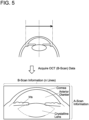
- the processor 60 identifies the positions of the respective parts of the subject eye E (such as the anterior and posterior surfaces of the cornea, the anterior and posterior surfaces of the crystalline lens and the retina) from the interference signals acquired for the respective scan angles (S20). Specifically, when the process of step S16 is executed for each of the scan angles, information on the interference signals (A-scan information) is acquired for each of those scan angles. Accordingly, as shown in FIG. 5 , two-dimensional information in which the interference signal information (the A-scan information) are arranged by a number of the scan angles (n lines) is acquired.
- the processor 60 identifies the positions of the respective parts of the subject eye E by calculating borderlines between the respective parts of the subject eye E (such as the cornea, the anterior chamber, an iris, and the crystalline lens) included in the respective interference signal information.
- the processor 60 writes acquired (captured) tomographic image data in the memory.
- the processor 60 determines whether or not the tomographic image data acquired in the aforementioned steps S14 to S20 has been acquired for all of time slots (timepoints of image capturing) that were preset before the measurement (S22).
- a plurality of tomographic images is acquired for a same cross section of the subject eye E in time series. That is, the processor 60 acquires B-scan information for the same cross section of the subject eye E with a preset time interval and with a preset number of times (that is, at all of the timepoints of image capturing within a preset image capturing period).
- step S22 In a case where tomographic images have not been acquired for all of the time slots (NO in step S22), the processor 60 returns to step S14, and the processes from step S14 are repeated. Due to this, the plurality of tomographic image data which have been acquired (captured) is written in the memory in a time series order. On the other hand, in a case where tomographic images have been acquired for all of the time slots (YES in step S22), the processor 60 proceeds to the subsequent process.
- an entropy of the generated interference signals is calculated from the acquired plurality of tomographic images (S24).
- the memory stores the plurality of tomographic image data for the same cross section of the subject eye E by the aforementioned processes up to step S22. Since the plurality of tomographic images is for the same cross section, a difference is less likely to occur among the plurality of images at a stationary part in the scattering sample. That is, the entropy at that part is low. On the other hand, a difference occurs more likely among the plurality of images at a dynamic part in the scattering sample. That is, the entropy at that part is high.
- the dynamic part in the tomographic images can be specified noninvasively and with high accuracy by calculating the entropy from the plurality of images acquired in time series. Further, in a conventional method of specifying a dynamic part from tomographic images, a measurement time for measuring a target region had to be long in order to specify whether a difference among the images captured in time series is caused due to being a dynamic part or due to noise. In the present embodiment, the dynamic part is specified by calculating the entropy, and thus a measurement time for measuring the target region can be made short.
- the dynamic part in the tomographic images may, for example, be a blood vessel in the subject eye E.
- a process of step S24 is executed by a procedure as follows.
- a complex signal of the interference light acquired at a time t is defined as g(t).
- a pair of complex signals of the interference light acquired at the time t and a time t+ ⁇ t is defined as in Math 1 as below.
- E(t) indicates an authentic complex signal (a complex signal that does not include noise component) at the time t, and ⁇ indicates an additive complex white noise.
- the processor 60 calculates an ensemble average of the covariance matrix of above Math 1.
- the ensemble average of the covariance matrix of Math 1 is represented as in Math 2 below.
- Each overline indicates an ensemble average
- the superscript dagger indicates Hermitian transpose
- each superscript asterisk indicates a complex conjugate.
- a pair of complex signals of the interference light acquired at a time t+n ⁇ t and a time t+(n+1) ⁇ t may be represented as in Math 3 below.
- the processor 60 may replace above Math 1 with Math 3 and calculate the ensemble average of the covariance matrix of Math 3. Further, although above Math 2 represents the ensemble average of the covariance matrix at one point in a space, multiple points in a spatially-defined kernel size may be included in the ensemble average.
- ⁇ 1 and ⁇ 2 are normalized as shown in Math 5 below.
- the processor 60 can calculate the entropy of the generated interference signals by using the plurality of tomographic image data for the same cross section of the subject eye E.
- the processor 60 may use either one of Math 6 and Math 8 as the entropy of the generated interference signals.
- Math 6 will be used as the entropy of the generated interference signals to facilitate explanation.
- the processor 60 calculates an entropy of noise component in the interference signals (S26).
- the entropy of the generated interference signals calculated in step S24 includes not only randomness which authentic interference signals have (hereinbelow termed an entropy of the authentic interference signals) but also randomness caused by the noise component (hereinbelow termed an entropy of the noise component).
- the entropy of the authentic interference signals and the entropy of the noise component are statistically not correlated with each other. Due to this, a sum of the entropy of the authentic interference signals and the entropy of the noise component matches the entropy of the generated interference signals. Therefore, in step S26, the entropy of the noise component is calculated to calculate the entropy of the authentic interference signals.
- a process of step S26 is executed by a procedure as follows. Aside from step S24 as above, tomographic images that measured only noise without setting a measurement target in the device are prepared and used for the process of step S26.
- the equation represented in above Math 1 is a vector with two rows and 1 column, similarly to a Jones vector. Further, Jones vector can be transformed to DOP (degree of polarization). Due to this, the equation represented in Math 1 can be transformed by applying a calculation method for transforming Jones vector to DOP. Then, the processor 60 transforms Math 1 to Math 9 below by using the calculation method for transforming Jones vector to DOP.
- DOP transformed from the Jones vectors can further be transformed to eigenvalues.
- the processor 60 transforms above Math 9 to Math 10 below by using a calculation method for transforming DOP, which has been transformed from Jones vector, to eigenvalues.
- ⁇ 1 1 + P 2
- ⁇ 2 1 ⁇ P 2
- H noise indicates the entropy of the noise component.
- the processor 60 calculates the entropy of the authentic interference signals (S28).
- the entropy of the authentic interference signals can be calculated by subtracting the entropy of the noise component from the entropy of the generated interference signals.
- an equation represented in Math 12 below is established.
- H subject indicates the entropy of the authentic interference signals.
- H subject H ⁇ H noise
- the processor 60 assigns the entropy of the interference signals calculated in step S24 and the entropy of the noise component calculated in step S26 to Math 12 to calculate the entropy of the authentic interference signals.
- the entropy of the generated interference signals and the entropy of the noise component are calculated independently from each other. Due to this, even if the interference signals are small, for example, the entropy of the generated interference signals and the entropy of the noise component can be calculated with high accuracy. Thus, the entropy of the authentic interference signals can more accurately be calculated.
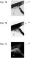
- FIGS. 6 and 7A to 7C show tomographic images near the corner angle of the subject eye E.
- FIG. 6 is an image indicating an intensity of the interference signals
- FIGS. 7A to 7C are images respectively indicating entropies at a portion matching that of the image of FIG. 6 .
- FIG. 7A is an image indicating the entropy of the generated interference signals
- FIG. 7B is an image indicating the entropy of the noise component
- FIGS. 7A to 7C is an image obtained by subtracting the entropy of the noise component from the entropy of the generated interference signals.
- a portion in FIGS. 7A to 7C denoted by a reference sign 70 indicates a part of the cornea
- a portion denoted by a reference sign 72 indicates a part of a ciliary body.
- portions with high entropy are shown in white and portions with low entropy are shown in black.
- the entropy is low in the portion 70 since no blood vessel is present in the cornea, and the entropy is high in the portion 72 since the ciliary body includes a large number of blood vessels. As shown in FIG. 7A , the entropy of the generated interference signals is extremely high in the portion 72 indicating the ciliary body, however, it is also relatively high in the portion 70 indicating the cornea as well, though it is somewhat lower than that of the portion 72 indicating the ciliary body.
- the entropy of the noise component is high in the portion 70 indicating the cornea. Accordingly, the entropy of the generated interference signals in the portion 70 indicating the cornea (see FIG. 7A ) can be said as being high due to the noise component. Further, the entropy of the noise component is somewhat high also in the portion 72 indicating the ciliary body. Due to this, the entropy of the generated interference signals in the portion 72 indicating the ciliary body (see FIG. 7A ) can also be said as including the noise component to some degree.
- the entropy of the interference signals became low in the portion 70 indicating the cornea. That is, it has been indicated that no blood vessel is present in the portion 70 indicating the cornea. Further, the entropy of the interference signals was sufficiently high in the portion 72 indicating the ciliary body. That is, it has been indicated that the large number of blood vessels are present in the portion 72 indicating the ciliary body. Thus, it has been confirmed that the entropy of the interference signals can accurately be calculated by subtracting the entropy of the noise component from the entropy of the generated interference signals.
- the processor 60 specifies a dynamic part of the subject eye E from the calculated entropy of the authentic interference signals (S30). Specifically, the processor 60 specifies a portion with high entropy of the authentic interference signals calculated in step S28 as the dynamic part of the subject eye E. When the dynamic part is specified, the processor 60 writes data of the image indicating the entropy of the authentic interference signals in the memory, and terminates the process of specifying the dynamic part of the subject eye E.
- the dynamic part is specified in the tomographic images of the single cross section, however, no limitation is placed to this configuration.
- the dynamic part specifying process as above may be executed while the position of a cross section of the subject eye E is changed, and three-dimensional data may be acquired from tomographic images for a plurality of cross sections.
- the tomographic images for the plurality of cross sections may be acquired by a radial scan scheme in which each scan line passes through an apex of the cornea. In so doing, the plurality tomographic images is captured for each cross section in time series. By so doing, the plurality of tomographic images of the subject eye E is acquired in time series for all of the cross sections.
- the tomographic images are acquired with a B-scan direction set in radial directions from the apex of the cornea of the subject eye E and a C-scan direction set in a circumferential direction thereof. Further, the processor 60 calculates the entropy of the authentic interference signals and specifies the dynamic part for the tomographic images of each cross section that were acquired, to construct three-dimensional data. Due to this, the three-dimensional data of the dynamic part of the subject eye E can be acquired.
- a method of acquiring the three-dimensional data is not particularly limited.
- the tomographic images for the plurality of cross sections may be acquired by a raster scan scheme.
- a front image of the subject eye E may be acquired by using the three-dimensional data of the entropy constructed as above (hereinbelow may be termed three-dimensional entropy data).
- the front image is, for example, an en face image.
- a maximum value, an average value and the like in the depth direction are calculated for each A-scan in the three-dimensional entropy data, and the three-dimensional data is compressed into a two-dimensional en face image.
- three-dimensional data may be acquired plural times for a same part in the subject eye E (such as the anterior part), and a maximum value and an average value at each position in a plurality of three-dimensional entropy data or at each position in a plurality of the two-dimensional entropy en face images may be calculated. Due to this, measurement noise can be reduced. Further, the data acquired plural times may not indicate exactly the same position, due to motions of the subject eye E. Thus, the measurement noise can more efficiently be reduced by carrying out accurate positioning for the part that was captured plural times prior to the calculation of the maximum value and the average value of the entropy at each position.
- the blood vessel in the subject eye E is specified, however, no limitation is placed to this configuration.
- Any dynamic part in the scattering sample can be specified by calculating the entropy from the plurality of tomographic images for the same cross section, and for example, not only the blood vessel in the anterior part of the eye, but also a blood vessel in the fundus, a cerebral vessel, and a hypodermic blood vessel can be specified.
- the optical coherence tomographic device specifies the dynamic part of the scattering sample by using OCT, however, a type of OCT is not particularly limited.
- the optical coherence tomographic device may be a polarization-sensitive optical coherence tomographic device.
Landscapes
- Health & Medical Sciences (AREA)
- Life Sciences & Earth Sciences (AREA)
- General Health & Medical Sciences (AREA)
- Physics & Mathematics (AREA)
- Medical Informatics (AREA)
- Animal Behavior & Ethology (AREA)
- Veterinary Medicine (AREA)
- Engineering & Computer Science (AREA)
- Biomedical Technology (AREA)
- Heart & Thoracic Surgery (AREA)
- Radiology & Medical Imaging (AREA)
- Molecular Biology (AREA)
- Surgery (AREA)
- Biophysics (AREA)
- Nuclear Medicine, Radiotherapy & Molecular Imaging (AREA)
- Public Health (AREA)
- Ophthalmology & Optometry (AREA)
- General Physics & Mathematics (AREA)
- Hematology (AREA)
- Pathology (AREA)
- Investigating Or Analysing Materials By Optical Means (AREA)
- Eye Examination Apparatus (AREA)
Claims (3)
- Optische Kohärenztomographievorrichtung, das Folgendes beinhaltet:eine Lichtquelle (12);einen Messlichtgenerator, der so gestaltet ist, dass er Messlicht durch Verwendung von Licht von der Lichtquelle (12) erzeugt und reflektiertes Licht von einem Zielbereich (E) in einer Streuprobe durch Bestrahlen des Zielbereichs (E) mit dem Messlicht erzeugt, wobei der Zielbereich (E) ein Blutgefäß umfasst;einen Referenzlichtgenerator, der so gestaltet ist, dass er Referenzlicht unter Verwendung des Lichts von der Lichtquelle (12) erzeugt;einen Interferenzlichtgenerator (10), der so gestaltet ist, dass er Interferenzlicht erzeugt durch Kombinieren des in dem Messlichtgenerator erzeugten reflektierten Lichts von der Zielregion (E) und des in dem Referenzlichtgenerator erzeugten Referenzlichts;einen Interferenzlichtdetektor (38), der so gestaltet ist, dass er das im Interferenzlichtgenerator (10) erzeugte Interferenzlicht erfasst und durch Umwandeln des Interferenzlichts Interferenzsignale erzeugt;einen Prozessor (60); undeinen Speicher, der computerlesbare Anweisungen darin speichert,dadurch gekennzeichnet, dassdie computerlesbaren Anweisungen, wenn sie vom Prozessor (60) ausgeführt werden, bewirken, dass die optische Kohärenztomographievorrichtung Folgendes ausführt:Zeitreihenerfassung einer Vielzahl von tomographischen Bildern für denselben Querschnitt in der Zielregion (E) aus den im Interferenzlichtdetektor (38) erzeugten Interferenzsignalen;Berechnen (S24) einer Entropie der erzeugten Interferenzsignale auf Grundlage der Vielzahl von in zeitlicher Abfolge erfassten tomographischen Bildern;Berechnen (S26) einer Entropie einer Rauschkomponente in den erzeugten Interferenzsignalen auf Grundlage der Vielzahl von in Zeitreihe erfassten tomographischen Bildern; undKorrigieren (S28) der Entropie der erzeugten Interferenzsignale durch Subtrahieren der Entropie der Rauschkomponente von der Entropie der erzeugten Interferenzsignale,Bestimmen (S30) eines dynamischen Teils in den tomographischen Bildern auf Grundlage der korrigierten Entropie der erzeugten Interferenzsignale;wobei der dynamische Teil das Blutgefäß ist, das von der Zielregion (E) umfasst wird.
- Optische Kohärenztomographievorrichtung nach Anspruch 1, wobei
die computerlesbaren Anweisungen, wenn sie vom Prozessor (60) ausgeführt werden, das optische Kohärenztomographiegerät ferner dazu veranlassen, Folgendes auszuführen:Erfassen einer Vielzahl von tomographischen Bildern für jeden einer Vielzahl von Querschnitten in der Zielregion (E) in einer Zeitreihe; undErzeugen von jeweils festgelegten tomographischen Bildern für die Vielzahl von Querschnitten durch Ausführen der Berechnung der Entropie der erzeugten Interferenzsignale und der Bestimmung des dynamischen Teils für jeden der Vielzahl von Querschnitten, wobei jedes der festgelegten tomographischen Bilder den dynamischen Teil in einem entsprechenden der Vielzahl von Querschnitten bestimmt. - Optische Kohärenztomographievorrichtung nach Anspruch 2, wobei
die computerlesbaren Anweisungen, wenn sie durch den Prozessor (60) ausgeführt werden, ferner bewirken, dass die optische Kohärenztomographievorrichtung Folgendes ausführt:
Erzeugen eines Frontbildes des Zielbereichs (E) unter Verwendung von dreidimensionalen Bilddaten, die durch Überlagern der festgelegten tomographischen Bilder erhalten werden.
Applications Claiming Priority (1)
| Application Number | Priority Date | Filing Date | Title |
|---|---|---|---|
| JP2018008265A JP7019128B2 (ja) | 2018-01-22 | 2018-01-22 | 光断層画像撮影装置 |
Publications (2)
| Publication Number | Publication Date |
|---|---|
| EP3513707A1 EP3513707A1 (de) | 2019-07-24 |
| EP3513707B1 true EP3513707B1 (de) | 2025-02-26 |
Family
ID=65351851
Family Applications (1)
| Application Number | Title | Priority Date | Filing Date |
|---|---|---|---|
| EP19152797.7A Active EP3513707B1 (de) | 2018-01-22 | 2019-01-21 | Vorrichtung für optische kohärenztomografie |
Country Status (4)
| Country | Link |
|---|---|
| US (1) | US11478146B2 (de) |
| EP (1) | EP3513707B1 (de) |
| JP (1) | JP7019128B2 (de) |
| CN (1) | CN110063714B (de) |
Families Citing this family (3)
| Publication number | Priority date | Publication date | Assignee | Title |
|---|---|---|---|---|
| US12510458B2 (en) * | 2020-06-18 | 2025-12-30 | Hamamatsu Photonics K.K. | Observation device and observation method using a low-speed camera as an imaging unit when observing a moving observation object |
| CN114909987B (zh) * | 2022-05-09 | 2024-02-02 | 东南大学 | 一种b扫描分割法抑制样品整体抖动的方法 |
| CN115778319B (zh) * | 2022-11-09 | 2024-05-07 | 山东大学 | 基于双光谱仪进行光源噪声补偿的可见光oct系统 |
Citations (1)
| Publication number | Priority date | Publication date | Assignee | Title |
|---|---|---|---|---|
| EP3278720A1 (de) * | 2016-08-05 | 2018-02-07 | Tomey Corporation | Vorrichtung für optische kohärenztomografie |
Family Cites Families (24)
| Publication number | Priority date | Publication date | Assignee | Title |
|---|---|---|---|---|
| JP2003516531A (ja) * | 1999-12-09 | 2003-05-13 | オーティーアイ オフサルミック テクノロジーズ インク | 可変奥行き解像力を有する光学マッピング装置 |
| EP1602321A1 (de) * | 2004-06-02 | 2005-12-07 | SensoMotoric Instruments GmbH | Methode und Gerät zur bildgestützten Augenverfolgung bei Apparaten zur Diagnose oder Chirurgie der Retina |
| JP4389032B2 (ja) * | 2007-01-18 | 2009-12-24 | 国立大学法人 筑波大学 | 光コヒーレンストモグラフィーの画像処理装置 |
| EP2173254A2 (de) * | 2007-07-31 | 2010-04-14 | The General Hospital Corporation | System und verfahren zur bereitstellung von strahlerfassungsmustern für hochgeschwindigkeits-abbildungen optischer dopplerfrequenzdomänen |
| JP5623028B2 (ja) * | 2009-01-23 | 2014-11-12 | キヤノン株式会社 | 光干渉断層画像を撮る撮像方法及びその装置 |
| US20130003077A1 (en) * | 2010-03-31 | 2013-01-03 | Canon Kabushiki Kaisha | Tomographic imaging apparatus and control apparatus for tomographic imaging apparatus |
| JP2012002597A (ja) * | 2010-06-15 | 2012-01-05 | Fujifilm Corp | 光断層画像化装置及び光断層画像化方法 |
| US20120188554A1 (en) * | 2011-01-24 | 2012-07-26 | Canon Kabushiki Kaisha | Light source device and imaging apparatus using the same |
| CA2844433A1 (en) | 2011-08-09 | 2013-02-14 | Optovue, Inc. | Motion correction and normalization of features in optical coherence tomography |
| DE102012019467A1 (de) * | 2012-09-28 | 2014-06-12 | Carl Zeiss Meditec Ag | Verfahren zur verlässlichen Bestimmung der Achslänge eines Auges |
| US9677869B2 (en) * | 2012-12-05 | 2017-06-13 | Perimeter Medical Imaging, Inc. | System and method for generating a wide-field OCT image of a portion of a sample |
| WO2014168930A1 (en) | 2013-04-09 | 2014-10-16 | University Of Washington Through Its Center For Commercialization | Methods and systems for determining hemodynamic properties of a tissue |
| JP6346410B2 (ja) * | 2013-05-24 | 2018-06-20 | 国立大学法人 筑波大学 | ジョーンズマトリックスoctシステム及び該octで得られた計測データを画像処理するプログラム |
| JP2015129730A (ja) * | 2014-01-09 | 2015-07-16 | 住友電気工業株式会社 | 光学的測定方法 |
| JP6606800B2 (ja) * | 2015-04-23 | 2019-11-20 | 株式会社トーメーコーポレーション | 偏光情報を利用した光干渉断層計 |
| CN104958061B (zh) * | 2015-07-28 | 2016-09-14 | 北京信息科技大学 | 双目立体视觉三维成像的眼底oct成像方法及其系统 |
| JP6602108B2 (ja) * | 2015-08-27 | 2019-11-06 | キヤノン株式会社 | 眼科装置、情報処理方法及びプログラム |
| JP6632267B2 (ja) * | 2015-09-04 | 2020-01-22 | キヤノン株式会社 | 眼科装置、表示制御方法およびプログラム |
| JP6624945B2 (ja) * | 2016-01-21 | 2019-12-25 | キヤノン株式会社 | 画像形成方法及び装置 |
| US10002435B2 (en) * | 2016-01-29 | 2018-06-19 | Google Llc | Detecting motion in images |
| US10453191B2 (en) * | 2016-04-20 | 2019-10-22 | Case Western Reserve University | Automated intravascular plaque classification |
| US10010247B2 (en) * | 2016-04-26 | 2018-07-03 | Optos Plc | Retinal image processing |
| JP6843602B2 (ja) * | 2016-12-05 | 2021-03-17 | キヤノン株式会社 | 画像表示装置、画像表示方法、及びプログラム |
| US10426337B2 (en) * | 2017-06-01 | 2019-10-01 | Santec Corporation | Flow imaging in an optical coherence tomography (OCT) system |
-
2018
- 2018-01-22 JP JP2018008265A patent/JP7019128B2/ja active Active
-
2019
- 2019-01-17 US US16/250,376 patent/US11478146B2/en active Active
- 2019-01-21 CN CN201910054816.5A patent/CN110063714B/zh active Active
- 2019-01-21 EP EP19152797.7A patent/EP3513707B1/de active Active
Patent Citations (1)
| Publication number | Priority date | Publication date | Assignee | Title |
|---|---|---|---|---|
| EP3278720A1 (de) * | 2016-08-05 | 2018-02-07 | Tomey Corporation | Vorrichtung für optische kohärenztomografie |
Also Published As
| Publication number | Publication date |
|---|---|
| EP3513707A1 (de) | 2019-07-24 |
| CN110063714B (zh) | 2023-12-29 |
| CN110063714A (zh) | 2019-07-30 |
| JP2019128180A (ja) | 2019-08-01 |
| US20190223717A1 (en) | 2019-07-25 |
| JP7019128B2 (ja) | 2022-02-15 |
| US11478146B2 (en) | 2022-10-25 |
Similar Documents
| Publication | Publication Date | Title |
|---|---|---|
| US9033500B2 (en) | Optical coherence tomography and method thereof | |
| EP2420181B1 (de) | Gerät zur inspektion des augenhintergrundes | |
| US9042622B2 (en) | Optical coherence tomographic apparatus, control method for optical coherence tomographic apparatus and storage medium | |
| US9875541B2 (en) | Enhanced algorithm for the detection of eye motion from fundus images | |
| US10912458B2 (en) | Ophthalmic apparatus | |
| US9554700B2 (en) | Optical coherence tomographic imaging apparatus and method of controlling the same | |
| EP2823752A1 (de) | Optische Kohärenztomografie mit dynamischer Fokusumschaltung und Fenstermittlung | |
| US10939817B2 (en) | Fundus imaging apparatus and imaging method | |
| KR20140029224A (ko) | 안과장치, 안과장치의 제어방법, 및 기억매체 | |
| EP3513707B1 (de) | Vorrichtung für optische kohärenztomografie | |
| JP2017046976A (ja) | 眼科撮影装置及び眼科撮影プログラム | |
| JP2017046975A (ja) | 眼科撮影装置及び眼科撮影プログラム | |
| US9918623B2 (en) | Optical tomographic imaging apparatus | |
| US10123699B2 (en) | Ophthalmologic apparatus and imaging method | |
| EP3050497A1 (de) | Ophthalmische vorrichtung und verfahren zur steuerung davon | |
| EP3375349B1 (de) | Informationsverarbeitungsvorrichtung, bilderzeugungsverfahren und computerlesbares medium | |
| US10188286B2 (en) | Tomographic image capturing device | |
| JP7410481B2 (ja) | 画像処理方法、走査型イメージング方法、画像処理装置、その制御方法、走査型イメージング装置、その制御方法、プログラム、及び記録媒体 | |
| US11074694B2 (en) | Image processing apparatus, optical coherence tomography apparatus, image processing method, and computer-readable medium | |
| CN111265185A (zh) | 眼科装置 | |
| JP2017046924A (ja) | 光干渉断層計及びその制御方法 | |
| US20200305719A1 (en) | Medical image processing device, oct device, and non-transitory computer-readable storage medium storing computer-readable instructions |
Legal Events
| Date | Code | Title | Description |
|---|---|---|---|
| PUAI | Public reference made under article 153(3) epc to a published international application that has entered the european phase |
Free format text: ORIGINAL CODE: 0009012 |
|
| STAA | Information on the status of an ep patent application or granted ep patent |
Free format text: STATUS: THE APPLICATION HAS BEEN PUBLISHED |
|
| AK | Designated contracting states |
Kind code of ref document: A1 Designated state(s): AL AT BE BG CH CY CZ DE DK EE ES FI FR GB GR HR HU IE IS IT LI LT LU LV MC MK MT NL NO PL PT RO RS SE SI SK SM TR |
|
| AX | Request for extension of the european patent |
Extension state: BA ME |
|
| STAA | Information on the status of an ep patent application or granted ep patent |
Free format text: STATUS: REQUEST FOR EXAMINATION WAS MADE |
|
| 17P | Request for examination filed |
Effective date: 20191218 |
|
| RBV | Designated contracting states (corrected) |
Designated state(s): AL AT BE BG CH CY CZ DE DK EE ES FI FR GB GR HR HU IE IS IT LI LT LU LV MC MK MT NL NO PL PT RO RS SE SI SK SM TR |
|
| STAA | Information on the status of an ep patent application or granted ep patent |
Free format text: STATUS: EXAMINATION IS IN PROGRESS |
|
| 17Q | First examination report despatched |
Effective date: 20220225 |
|
| GRAP | Despatch of communication of intention to grant a patent |
Free format text: ORIGINAL CODE: EPIDOSNIGR1 |
|
| STAA | Information on the status of an ep patent application or granted ep patent |
Free format text: STATUS: GRANT OF PATENT IS INTENDED |
|
| INTG | Intention to grant announced |
Effective date: 20240925 |
|
| P01 | Opt-out of the competence of the unified patent court (upc) registered |
Free format text: CASE NUMBER: APP_64402/2024 Effective date: 20241205 |
|
| GRAS | Grant fee paid |
Free format text: ORIGINAL CODE: EPIDOSNIGR3 |
|
| GRAA | (expected) grant |
Free format text: ORIGINAL CODE: 0009210 |
|
| STAA | Information on the status of an ep patent application or granted ep patent |
Free format text: STATUS: THE PATENT HAS BEEN GRANTED |
|
| AK | Designated contracting states |
Kind code of ref document: B1 Designated state(s): AL AT BE BG CH CY CZ DE DK EE ES FI FR GB GR HR HU IE IS IT LI LT LU LV MC MK MT NL NO PL PT RO RS SE SI SK SM TR |
|
| REG | Reference to a national code |
Ref country code: GB Ref legal event code: FG4D |
|
| REG | Reference to a national code |
Ref country code: CH Ref legal event code: EP |
|
| REG | Reference to a national code |
Ref country code: DE Ref legal event code: R096 Ref document number: 602019066397 Country of ref document: DE |
|
| REG | Reference to a national code |
Ref country code: IE Ref legal event code: FG4D |
|
| REG | Reference to a national code |
Ref country code: NL Ref legal event code: MP Effective date: 20250226 |
|
| PG25 | Lapsed in a contracting state [announced via postgrant information from national office to epo] |
Ref country code: RS Free format text: LAPSE BECAUSE OF FAILURE TO SUBMIT A TRANSLATION OF THE DESCRIPTION OR TO PAY THE FEE WITHIN THE PRESCRIBED TIME-LIMIT Effective date: 20250526 |
|
| PG25 | Lapsed in a contracting state [announced via postgrant information from national office to epo] |
Ref country code: FI Free format text: LAPSE BECAUSE OF FAILURE TO SUBMIT A TRANSLATION OF THE DESCRIPTION OR TO PAY THE FEE WITHIN THE PRESCRIBED TIME-LIMIT Effective date: 20250226 |
|
| PG25 | Lapsed in a contracting state [announced via postgrant information from national office to epo] |
Ref country code: PL Free format text: LAPSE BECAUSE OF FAILURE TO SUBMIT A TRANSLATION OF THE DESCRIPTION OR TO PAY THE FEE WITHIN THE PRESCRIBED TIME-LIMIT Effective date: 20250226 |
|
| PG25 | Lapsed in a contracting state [announced via postgrant information from national office to epo] |
Ref country code: ES Free format text: LAPSE BECAUSE OF FAILURE TO SUBMIT A TRANSLATION OF THE DESCRIPTION OR TO PAY THE FEE WITHIN THE PRESCRIBED TIME-LIMIT Effective date: 20250226 |
|
| REG | Reference to a national code |
Ref country code: LT Ref legal event code: MG9D |
|
| PG25 | Lapsed in a contracting state [announced via postgrant information from national office to epo] |
Ref country code: IS Free format text: LAPSE BECAUSE OF FAILURE TO SUBMIT A TRANSLATION OF THE DESCRIPTION OR TO PAY THE FEE WITHIN THE PRESCRIBED TIME-LIMIT Effective date: 20250626 Ref country code: NO Free format text: LAPSE BECAUSE OF FAILURE TO SUBMIT A TRANSLATION OF THE DESCRIPTION OR TO PAY THE FEE WITHIN THE PRESCRIBED TIME-LIMIT Effective date: 20250526 |
|
| PG25 | Lapsed in a contracting state [announced via postgrant information from national office to epo] |
Ref country code: NL Free format text: LAPSE BECAUSE OF FAILURE TO SUBMIT A TRANSLATION OF THE DESCRIPTION OR TO PAY THE FEE WITHIN THE PRESCRIBED TIME-LIMIT Effective date: 20250226 |
|
| PG25 | Lapsed in a contracting state [announced via postgrant information from national office to epo] |
Ref country code: HR Free format text: LAPSE BECAUSE OF FAILURE TO SUBMIT A TRANSLATION OF THE DESCRIPTION OR TO PAY THE FEE WITHIN THE PRESCRIBED TIME-LIMIT Effective date: 20250226 |
|
| PG25 | Lapsed in a contracting state [announced via postgrant information from national office to epo] |
Ref country code: PT Free format text: LAPSE BECAUSE OF FAILURE TO SUBMIT A TRANSLATION OF THE DESCRIPTION OR TO PAY THE FEE WITHIN THE PRESCRIBED TIME-LIMIT Effective date: 20250626 Ref country code: LV Free format text: LAPSE BECAUSE OF FAILURE TO SUBMIT A TRANSLATION OF THE DESCRIPTION OR TO PAY THE FEE WITHIN THE PRESCRIBED TIME-LIMIT Effective date: 20250226 |
|
| PG25 | Lapsed in a contracting state [announced via postgrant information from national office to epo] |
Ref country code: GR Free format text: LAPSE BECAUSE OF FAILURE TO SUBMIT A TRANSLATION OF THE DESCRIPTION OR TO PAY THE FEE WITHIN THE PRESCRIBED TIME-LIMIT Effective date: 20250527 Ref country code: BG Free format text: LAPSE BECAUSE OF FAILURE TO SUBMIT A TRANSLATION OF THE DESCRIPTION OR TO PAY THE FEE WITHIN THE PRESCRIBED TIME-LIMIT Effective date: 20250226 |
|
| REG | Reference to a national code |
Ref country code: AT Ref legal event code: MK05 Ref document number: 1769807 Country of ref document: AT Kind code of ref document: T Effective date: 20250226 |
|
| PG25 | Lapsed in a contracting state [announced via postgrant information from national office to epo] |
Ref country code: SE Free format text: LAPSE BECAUSE OF FAILURE TO SUBMIT A TRANSLATION OF THE DESCRIPTION OR TO PAY THE FEE WITHIN THE PRESCRIBED TIME-LIMIT Effective date: 20250226 |
|
| PG25 | Lapsed in a contracting state [announced via postgrant information from national office to epo] |
Ref country code: SM Free format text: LAPSE BECAUSE OF FAILURE TO SUBMIT A TRANSLATION OF THE DESCRIPTION OR TO PAY THE FEE WITHIN THE PRESCRIBED TIME-LIMIT Effective date: 20250226 |
|
| PG25 | Lapsed in a contracting state [announced via postgrant information from national office to epo] |
Ref country code: DK Free format text: LAPSE BECAUSE OF FAILURE TO SUBMIT A TRANSLATION OF THE DESCRIPTION OR TO PAY THE FEE WITHIN THE PRESCRIBED TIME-LIMIT Effective date: 20250226 |
|
| PG25 | Lapsed in a contracting state [announced via postgrant information from national office to epo] |
Ref country code: IT Free format text: LAPSE BECAUSE OF FAILURE TO SUBMIT A TRANSLATION OF THE DESCRIPTION OR TO PAY THE FEE WITHIN THE PRESCRIBED TIME-LIMIT Effective date: 20250226 |
|
| PG25 | Lapsed in a contracting state [announced via postgrant information from national office to epo] |
Ref country code: AT Free format text: LAPSE BECAUSE OF FAILURE TO SUBMIT A TRANSLATION OF THE DESCRIPTION OR TO PAY THE FEE WITHIN THE PRESCRIBED TIME-LIMIT Effective date: 20250226 |
|
| PG25 | Lapsed in a contracting state [announced via postgrant information from national office to epo] |
Ref country code: EE Free format text: LAPSE BECAUSE OF FAILURE TO SUBMIT A TRANSLATION OF THE DESCRIPTION OR TO PAY THE FEE WITHIN THE PRESCRIBED TIME-LIMIT Effective date: 20250226 Ref country code: CZ Free format text: LAPSE BECAUSE OF FAILURE TO SUBMIT A TRANSLATION OF THE DESCRIPTION OR TO PAY THE FEE WITHIN THE PRESCRIBED TIME-LIMIT Effective date: 20250226 |
|
| PG25 | Lapsed in a contracting state [announced via postgrant information from national office to epo] |
Ref country code: RO Free format text: LAPSE BECAUSE OF FAILURE TO SUBMIT A TRANSLATION OF THE DESCRIPTION OR TO PAY THE FEE WITHIN THE PRESCRIBED TIME-LIMIT Effective date: 20250226 |
|
| PG25 | Lapsed in a contracting state [announced via postgrant information from national office to epo] |
Ref country code: SK Free format text: LAPSE BECAUSE OF FAILURE TO SUBMIT A TRANSLATION OF THE DESCRIPTION OR TO PAY THE FEE WITHIN THE PRESCRIBED TIME-LIMIT Effective date: 20250226 |
|
| REG | Reference to a national code |
Ref country code: DE Ref legal event code: R097 Ref document number: 602019066397 Country of ref document: DE |
|
| PLBE | No opposition filed within time limit |
Free format text: ORIGINAL CODE: 0009261 |
|
| STAA | Information on the status of an ep patent application or granted ep patent |
Free format text: STATUS: NO OPPOSITION FILED WITHIN TIME LIMIT |
|
| 26N | No opposition filed |
Effective date: 20251127 |
|
| PGFP | Annual fee paid to national office [announced via postgrant information from national office to epo] |
Ref country code: DE Payment date: 20251203 Year of fee payment: 8 |