EP3512758B1 - Verfahren zur fahrunterstützung, verfahren zur implementierung solch eines verfahrens und vorrichtung zur fahrunterstützung - Google Patents
Verfahren zur fahrunterstützung, verfahren zur implementierung solch eines verfahrens und vorrichtung zur fahrunterstützung Download PDFInfo
- Publication number
- EP3512758B1 EP3512758B1 EP17780473.9A EP17780473A EP3512758B1 EP 3512758 B1 EP3512758 B1 EP 3512758B1 EP 17780473 A EP17780473 A EP 17780473A EP 3512758 B1 EP3512758 B1 EP 3512758B1
- Authority
- EP
- European Patent Office
- Prior art keywords
- vehicle
- obstacle
- trajectory
- distance
- detected
- Prior art date
- Legal status (The legal status is an assumption and is not a legal conclusion. Google has not performed a legal analysis and makes no representation as to the accuracy of the status listed.)
- Active
Links
Images
Classifications
-
- B—PERFORMING OPERATIONS; TRANSPORTING
- B60—VEHICLES IN GENERAL
- B60K—ARRANGEMENT OR MOUNTING OF PROPULSION UNITS OR OF TRANSMISSIONS IN VEHICLES; ARRANGEMENT OR MOUNTING OF PLURAL DIVERSE PRIME-MOVERS IN VEHICLES; AUXILIARY DRIVES FOR VEHICLES; INSTRUMENTATION OR DASHBOARDS FOR VEHICLES; ARRANGEMENTS IN CONNECTION WITH COOLING, AIR INTAKE, GAS EXHAUST OR FUEL SUPPLY OF PROPULSION UNITS IN VEHICLES
- B60K31/00—Vehicle fittings, acting on a single sub-unit only, for automatically controlling vehicle speed, i.e. preventing speed from exceeding an arbitrarily established velocity or maintaining speed at a particular velocity, as selected by the vehicle operator
- B60K31/0008—Vehicle fittings, acting on a single sub-unit only, for automatically controlling vehicle speed, i.e. preventing speed from exceeding an arbitrarily established velocity or maintaining speed at a particular velocity, as selected by the vehicle operator including means for detecting potential obstacles in vehicle path
-
- B—PERFORMING OPERATIONS; TRANSPORTING
- B60—VEHICLES IN GENERAL
- B60Q—ARRANGEMENT OF SIGNALLING OR LIGHTING DEVICES, THE MOUNTING OR SUPPORTING THEREOF OR CIRCUITS THEREFOR, FOR VEHICLES IN GENERAL
- B60Q9/00—Arrangement or adaptation of signal devices not provided for in one of main groups B60Q1/00 - B60Q7/00, e.g. haptic signalling
- B60Q9/002—Arrangement or adaptation of signal devices not provided for in one of main groups B60Q1/00 - B60Q7/00, e.g. haptic signalling for parking purposes, e.g. for warning the driver that his vehicle has contacted or is about to contact an obstacle
- B60Q9/004—Arrangement or adaptation of signal devices not provided for in one of main groups B60Q1/00 - B60Q7/00, e.g. haptic signalling for parking purposes, e.g. for warning the driver that his vehicle has contacted or is about to contact an obstacle using wave sensors
-
- B—PERFORMING OPERATIONS; TRANSPORTING
- B60—VEHICLES IN GENERAL
- B60Q—ARRANGEMENT OF SIGNALLING OR LIGHTING DEVICES, THE MOUNTING OR SUPPORTING THEREOF OR CIRCUITS THEREFOR, FOR VEHICLES IN GENERAL
- B60Q9/00—Arrangement or adaptation of signal devices not provided for in one of main groups B60Q1/00 - B60Q7/00, e.g. haptic signalling
- B60Q9/002—Arrangement or adaptation of signal devices not provided for in one of main groups B60Q1/00 - B60Q7/00, e.g. haptic signalling for parking purposes, e.g. for warning the driver that his vehicle has contacted or is about to contact an obstacle
- B60Q9/007—Arrangement or adaptation of signal devices not provided for in one of main groups B60Q1/00 - B60Q7/00, e.g. haptic signalling for parking purposes, e.g. for warning the driver that his vehicle has contacted or is about to contact an obstacle providing information about the distance to an obstacle, e.g. varying sound
-
- B—PERFORMING OPERATIONS; TRANSPORTING
- B62—LAND VEHICLES FOR TRAVELLING OTHERWISE THAN ON RAILS
- B62D—MOTOR VEHICLES; TRAILERS
- B62D15/00—Steering not otherwise provided for
- B62D15/02—Steering position indicators ; Steering position determination; Steering aids
- B62D15/025—Active steering aids, e.g. helping the driver by actively influencing the steering system after environment evaluation
- B62D15/0265—Automatic obstacle avoidance by steering
-
- B—PERFORMING OPERATIONS; TRANSPORTING
- B62—LAND VEHICLES FOR TRAVELLING OTHERWISE THAN ON RAILS
- B62D—MOTOR VEHICLES; TRAILERS
- B62D15/00—Steering not otherwise provided for
- B62D15/02—Steering position indicators ; Steering position determination; Steering aids
- B62D15/027—Parking aids, e.g. instruction means
- B62D15/0275—Parking aids, e.g. instruction means by overlaying a vehicle path based on present steering angle over an image without processing that image
-
- B—PERFORMING OPERATIONS; TRANSPORTING
- B62—LAND VEHICLES FOR TRAVELLING OTHERWISE THAN ON RAILS
- B62D—MOTOR VEHICLES; TRAILERS
- B62D15/00—Steering not otherwise provided for
- B62D15/02—Steering position indicators ; Steering position determination; Steering aids
- B62D15/029—Steering assistants using warnings or proposing actions to the driver without influencing the steering system
- B62D15/0295—Steering assistants using warnings or proposing actions to the driver without influencing the steering system by overlaying a vehicle path based on present steering angle over an image without processing that image
-
- G—PHYSICS
- G08—SIGNALLING
- G08G—TRAFFIC CONTROL SYSTEMS
- G08G1/00—Traffic control systems for road vehicles
- G08G1/16—Anti-collision systems
- G08G1/165—Anti-collision systems for passive traffic, e.g. including static obstacles, trees
-
- B—PERFORMING OPERATIONS; TRANSPORTING
- B60—VEHICLES IN GENERAL
- B60R—VEHICLES, VEHICLE FITTINGS, OR VEHICLE PARTS, NOT OTHERWISE PROVIDED FOR
- B60R2300/00—Details of viewing arrangements using cameras and displays, specially adapted for use in a vehicle
- B60R2300/80—Details of viewing arrangements using cameras and displays, specially adapted for use in a vehicle characterised by the intended use of the viewing arrangement
- B60R2300/8093—Details of viewing arrangements using cameras and displays, specially adapted for use in a vehicle characterised by the intended use of the viewing arrangement for obstacle warning
Definitions
- the present invention relates generally to the automotive field.
- It relates more particularly to the field of driving assistance methods for motor vehicle drivers.
- It also relates to a method for implementing this method in a motor vehicle.
- a driving assistance method is known according to which it is possible to detect an obstacle near a vehicle, and to indicate to the driver the approximate zone of its location in the environment of the vehicle.
- the environment surrounding the vehicle is represented schematically on a screen of the vehicle by a plurality of zones surrounding this vehicle.
- the zones are all off or grayed out.
- the method warns the driver of the presence of this obstacle by making this zone stand out in relation to the other zones, for example by lighting or coloring this zone.
- This method further indicates to the driver the approximate distance of the obstacle from the vehicle. For example, if the obstacle is relatively far from the vehicle, the area is colored green, and as the vehicle approaches the obstacle, the area is colored orange and then red.
- the driver does not know whether he will really come into contact with the obstacle.
- the driver must himself to deduce, for example according to the evolution of the colors of the zones, if it moves away or approaches the obstacle.
- the present invention proposes a more precise driving aid method making it possible to indicate to the driver whether he risks coming into contact with the obstacle detected. or if this obstacle is simply present in the environment of the vehicle without danger of percussion.
- the driver can visualize the trajectory of the vehicle, which allows him to see whether or not there is a risk of hitting the obstacle detected.
- driving is made easier because the driver visualizes the impact of a change in orientation of the wheels on the trajectory, and consequently on the avoidance or not of the obstacle.
- the driver sees whether the change in orientation of the wheels is sufficient to avoid the obstacle or whether a maneuver is necessary.
- the driving aid method can be easily installed on any type of vehicle.
- the implementation method according to the invention associated with the driving assistance method according to the invention allows a generality of implementation of said method.
- At least one image sensor suitable for capturing an image of said obstacle, and for communicating with said computer so that the screen displays a graphic representation of the obstacle captured.
- the environment of the vehicle corresponds to a zone outside the vehicle, located close to this vehicle and all around the latter.
- the environment of the vehicle corresponds to a strip between 0 and 3 meters (m) in width, or between 0 and 2m in width, surrounding the vehicle, the width of the strip being given from the body of the vehicle, in a direction normal to the point of the body in question.
- the front of the vehicle is the zone located outside the vehicle, surrounding the vehicle from the front, that is to say by the bonnet, and connecting the two front wheels to one another.
- the rear of the vehicle is the area located outside the vehicle, surrounding the vehicle from the rear, that is to say by the trunk, and connecting the two rear wheels to each other.
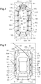
- two display screens 1 have been shown; 2 in accordance with a first and a second embodiment of a device 100 for driving assistance for a driver of a motor vehicle, respectively.
- the first and second embodiments of the device 100 according to the invention are respectively associated with first and second embodiments of a driving assistance method according to the invention.
- the angular sensor 101 is suitable for determining the angular position of the steering wheel, that is to say the angle of rotation of the steering wheel measured with respect to a reference position of this steering wheel.
- the angular position of the steering wheel is linked to the orientation of the two front wheels of the vehicle. It can also be linked to the orientation of the two front wheels and the two rear wheels of the vehicle in the case of vehicles with four steered wheels.
- the angular position, determined by the angular sensor 101, is given in degrees (°).
- the reference position of the steering wheel corresponds to the position of the steering wheel in which the four wheels of the vehicle are aligned and parallel.
- Angular position is associated with a positive angle when the steering wheel is turned to the right, and with a negative angle when the steering wheel is turned to the left.
- the angular position is between -N ° and + N °, the zero angle of 0 ° corresponding to the reference position of the steering wheel, that is to say to the rectilinear orientation of the four wheels of the aligned vehicle. and parallels.
- N is for example greater than or equal to 360.
- the value of N corresponds to the fact that it is necessary to turn the steering wheel several times to reach the maximum rotation of the wheels, in one direction or the other.
- the steering wheel reaches the maximum deflection, that is to say when it is at the end of its travel, the angular position is itself maximum, in absolute value.
- the angular sensor 101 is an electronic sensor connected to a support axis of the steering wheel of the vehicle.
- the obstacle detector 102 comprises a plurality of ultrasonic sensors 104 distributed around the vehicle.
- the ultrasonic sensors 104 are adapted to send and receive ultrasound to probe the environment of the vehicle and to detect any obstacles therein.
- each ultrasound sensor 104 operates in the manner of a radar, that is to say it comprises a transmitter suitable for sending ultrasound and a receiver suitable for receiving ultrasound.
- the emitted ultrasound is reflected when it encounters an obstacle so that it is likely to be received by the sensor that sent them.
- Each ultrasound sensor 104 is thus adapted to detect the presence of an obstacle and, by measuring the time of flight of the ultrasound, to evaluate the distance from this obstacle.
- the detector 102 here comprises twelve ultrasonic sensors 104 mounted on the vehicle, only three of these ultrasonic sensors 104 being shown in the figure. figure 4 . Six of these ultrasonic sensors 104 are arranged at the front of the vehicle and six others are arranged at the rear of the vehicle.
- the ultrasonic sensors 104 are distributed so as to be able to probe the front environment and the rear environment of the vehicle.
- each ultrasonic sensor 104 is suitable for probing, at the front and at the rear of the vehicle, a band between 0 and Da, from the body of the vehicle, in each direction normal to each point of the body considered. .
- Da is a distance, for example equal to 2 meters or to 1.2 meters.
- the obstacle detector 102 thus formed is adapted to communicate with the computer 103 of the device 100.
- Db is a distance for example equal to 1.2 meters, 1 meter or even 60 centimeters.
- This deduction is made by the computer 103 from the front and rear detections made by the ultrasonic sensors 104, of the speed of the vehicle and of the trajectory of said vehicle.
- the fact of having ultrasonic sensors 104 only at the front and at the rear makes it possible to use fewer ultrasonic sensors while guaranteeing a satisfactory survey of the environment of the vehicle.
- said device further comprises at least one image sensor suitable for capturing at least one image of the environment of the vehicle, in particular of the obstacle detected by the ultrasonic sensors.
- the image sensor is for example a camera suitable for capturing several images of the obstacle in the environment of the vehicle.
- said device comprises for example four cameras, each adapted to capture an image of the environment of the vehicle, in particular of the obstacle detected in this environment.
- the four cameras are respectively arranged on the vehicle body, at the front end of the vehicle, at the rear end of the vehicle, and under each side mirror of the vehicle.
- the cameras of the second embodiment of the device according to the invention it is possible to display on the display screen of the device a representation of the environment observed by the cameras, and in particular , if applicable, of the obstacle detected by the ultrasonic sensors.
- the driver has an idea of the nature of the obstacle detected, of its shape, and possibly of its dimension in a plane parallel to the ground.
- the computer 103 is suitable for receiving information from the angular sensor 101 of the device.
- the computer 103 is also adapted to receive the speed of the vehicle, and its direction of travel, namely whether reverse gear is engaged or if another speed is engaged.
- the computer 103 is adapted to deduce the orientation of the two front wheels of the vehicle from the only angular position of the steering wheel.
- the computer When the vehicle is fitted with four steered wheels, the computer is adapted to deduce the orientation of the four wheels of the vehicle from the angular position of the steering wheel and from the speed of movement of the vehicle.
- the computer 103 is also suitable for determining the trajectory of the vehicle from the orientation of the two front wheels of the vehicle, or even of the four wheels of the vehicle.
- the trajectory is a prediction of the path that the front wheel of the vehicle and the rear wheel diametrically opposite to this front wheel will travel.
- the trajectory corresponds to the prediction of the path that the right front wheel and the left rear wheel will travel, regardless of the direction of travel of the vehicle.
- the trajectory corresponds to the prediction of the path that the left front wheel and the right rear wheel will travel, regardless of the direction of travel of the vehicle.
- the trajectory is the prediction of the largest footprint that the moving vehicle would leave on the road.
- the computer 103 determines the trajectory in real time, so that the trajectory is recalculated as the steering wheel rotates.
- the computer 103 is adapted to receive information from the detector 102.
- the computer 103 is adapted to receive information from the various ultrasonic sensors 104.
- the computer 103 receives the time elapsed between the emission and the reception of ultrasound by each ultrasound sensor 104 having detected an obstacle.
- the computer 103 is thus adapted, from the trajectory of the vehicle, the speed of the vehicle and the ultrasound travel times, to deduce the relative position of the obstacle with respect to the ultrasonic sensors 104 which have detected the obstacle, and therefore in relation to the vehicle.
- the computer also receives at least one image of the obstacle captured by the image sensor.
- the computer is then suitable for generating a graphic representation of the obstacle in a top view called “ bird view ” of the vehicle, displayed on the display screen 1; 2.
- the computer 103 controls the display of the screen 1; 2.
- the display screen 1; 2 is arranged in the vehicle so as to be visible to the driver.
- screen 1; 2 comprises for example approximately 230 pixels in height and 150 pixels in width.
- the screen 1; 2 is suitable here for displaying information in color, for example at least in green, orange, red and blue.
- the screen is suitable for displaying information in different levels of white, gray and black.
- the screen 1; 2 is adapted to display a graphic representation of the environment of the vehicle, said representation being divided into several parts 10; 20 geometric shapes.
- screens 1; 2 respective first and second embodiments of the device are each adapted to display fourteen parts 10; 20 contiguous to each other.
- the area at the front of the vehicle is represented by the five parts 10M, 10N, 10A, 10B, 10C; 20M, 20N, 20A, 20B, 20C juxtaposed located at the top of the screen 1; 2, as shown in the figures 1, 2 .
- the zone located at the rear of the vehicle is represented by the five parts 10J, 10I, 10H, 10G 10F; 20J, 20I, 20H, 20G 20F juxtaposed located at the bottom of the screen, as shown on the drawing board.
- the side zones are represented by the two parts 10L, 10K; 20L, 20K juxtaposed to the right on the figures 1 and 2 and the two parts 10D, 10E; 20D, 20E juxtaposed on the left on the figures 1 and 2 , said parts 10L, 10K, 10D, 10E; 20L, 20K, 20D, 20E being located in the middle zone of the screen 1; 2.
- the vehicle is not shown on the screen 1 of the first embodiment of the device 100, but it is virtually located in the central zone surrounded by the different parts 10.
- each of the parts 10 surrounding the central zone is subdivided into at least three longitudinal bands: the so-called “outer” band is furthest from the central area, the so-called “outer” band. internal ”is closest to the central zone, and the so-called“ intermediate ”band is that between the two inner and outer bands.
- the part 10A which represents the zone extending the front hood of the vehicle and the part 10H which represents the zone extending the rear trunk are each subdivided into 4 longitudinal bands.
- These two specific parts 10A and 10H comprise two outer bands, an intermediate band and an inner band.
- the vehicle 3 is shown in a top view (“ bird view ”). It is located in the central area surrounded by all 20 parts.
- the display screen 1; 2 is also suitable for displaying an envelope 50 representative of the trajectory of the vehicle calculated by the computer 103.
- This envelope 50 comprises in practice two lines representing the prediction of the footprint that one of the front wheels and the rear wheel would make on the ground diametrically opposed to this front wheel, as a function of the angular position of the steering wheel.
- the envelope 50 is superimposed on the parts 10; 20 representing the environment of the vehicle.
- the display screen 1; 2 is further adapted to display the indicator representative of the relative position of the obstacle detected with respect to the trajectory and to the motor vehicle.
- This indicator comprises a first visual signal, emitted when the distance between the vehicle and said obstacle is less than a threshold value.
- the distance between the vehicle and said obstacle is considered to be the smallest distance existing between the vehicle and the obstacle. In other words, it is the distance measured in the direction of a normal to the body of the vehicle passing through the obstacle.
- the display screen 1; 2 makes it possible to visually warn the driver of the presence of an obstacle in his close environment.
- display screen 1; 2 warns the driver if an obstacle is detected at a distance less than or equal to D from the bodywork, measured in a direction normal to the bodywork and passing through the obstacle.
- the distance D is a distance less than or equal to the detection (or deduction) distance of the ultrasonic sensors, that is to say less than or equal to Da (or to Db).
- the distance D is for example chosen to be equal to 1.2 meters.
- the first signal corresponds to the at least partial illumination of at least one of the parts 10, each illuminated part 10 being selected as a function of the position of the obstacle by in relation to this part 10.
- the illuminated part 10 is that representing the zone of the environment in which the obstacle is physically located.
- the first signal corresponds to a graphic representation of the obstacle detected, said graphic representation being determined from said image captured by the image sensor.
- the driver thus has a better idea of the obstacle in question, in particular of its nature, its shape and possibly its dimensions in top view, that is to say out of height.
- the indicator displayed by the screen 1; 2 further comprises a second visual signal, emitted when the distance between the vehicle and said obstacle is less than a threshold value and that the detected obstacle is placed on the path of the vehicle.
- the second visual signal is distinct from the first visual signal and here is added to the first visual signal.
- the display screen 1; 2 of the device alerts the driver of this situation.
- the second visual signal corresponds to a particular mode of illumination of said illuminated part 10, said illumination mode being chosen as a function of the position of said illuminated part 10 with respect to the trajectory of the vehicle.
- the illumination mode here corresponds to the illumination of the part with a particular light intensity.
- the obstacle is located on the predicted route, that is to say on the calculated trajectory of the vehicle, the part representing the area in which the obstacle is located lights up with high intensity.
- the part representing the zone in which the obstacle is located lights up with a lower intensity.
- said second visual signal corresponds to the illumination of at least one of the parts 20 representing the environment of the vehicle, said illuminated part 20 being selected as a function of the position of the vehicle. 'obstacle in relation to this part 20.
- the obstacle is located on the predicted route of the vehicle, not only the obstacle is represented graphically on the screen, but in addition the part 20 representing the zone in which the obstacle is located lights up.
- the obstacle is only located at a distance from the vehicle less than D, without being on the planned route of the vehicle, only the graphic representation of the obstacle is displayed on the screen, without the part 20 representing the zone in which the obstacle is located does not light up.
- the indicator to further include information relating to the distance between the obstacle detected and said vehicle.
- the distance between the obstacle and the vehicle is represented on the screen 1 by the various longitudinal, internal, intermediate and external bands, cutting each part 10.
- D2 is a distance less than the distance D, for example equal to 70 centimeters.
- the outer and intermediate bands of the corresponding part 10 light up.
- D1 is here a distance less than D2, for example equal to 30 centimeters.
- each strip is illuminated in a color which is specific to it.
- the outer bands are illuminated in green
- the middle bands are illuminated in orange
- the inner bands are illuminated in red.
- the green color is materialized by dots, the orange color by oblique hatching and the red color by hatching perpendicular to the bodywork.
- the distance between the obstacle and the vehicle is represented on the screen 2 by a specific color of the illuminated part 20.
- the indicator only includes information relating to the distance when the obstacle is located in the path of the vehicle.
- the corresponding part lights up in green, in totality.
- D2 is a distance less than the distance D, for example equal to 70 centimeters, as in the first embodiment.
- the corresponding part 20 lights up in orange, in full. .
- D1 is here a distance less than D2, for example equal to 30 centimeters, as in the first embodiment.
- the corresponding part 20 lights up in red, in full. .
- the display screen 1; 2 of each embodiment of the device 100 according to the invention is therefore suitable for displaying different indicators, obtained respectively according to the first embodiment of the driving assistance method according to the invention and according to the second mode of implementation of the method according to the invention.
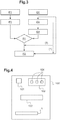
- step a) represented by box P1 on the figure 3 , the angular sensor 101 determines the angular position of the steering wheel and sends to the computer 103 the corresponding angle of the steering wheel.
- This step is identical for the two embodiments of the invention.
- step b the emitters of the various ultrasonic sensors 104 of the detector 102 send ultrasound to probe the environment of the vehicle.
- the detector 102 When the ultrasounds are received by at least one receiver of the various ultrasonic sensors 104, the detector 102 considers that an obstacle is detected because it is it which reflected the said ultrasounds initially emitted.
- the image sensors capture images of the environment of the vehicle.
- At least one image sensor captures at least one image of the obstacle.
- step c whatever the mode of implementation of the method, the computer 103 calculates the trajectory of the vehicle from the angular position of the steering wheel determined in step a). This step is represented by box P2 on the figure 3 .
- step b the computer 103 calculates, in step c), the distance between said obstacle and the receiver of the ultrasonic sensor 104 having received the ultrasound reflected by the obstacle .
- the computer 103 calculates this distance as a function of the speed of the vehicle, of the trajectory of said vehicle estimated previously, and of the travel time of the ultrasounds, that is to say of the time elapsed between their emission and their reception by the sensor.
- the computer 103 then deduces, as a function of the dimensions of the vehicle, the distance between said obstacle and the vehicle, that is to say the shortest distance existing between the obstacle and the vehicle. This distance is that measured in the direction of a normal to the body of the vehicle passing through the obstacle.
- This step is represented by box Q2 of the figure 3 .
- step c) the computer 103 identifies the zone of the environment of the vehicle in which said obstacle is located. This step is represented by box Q3 on the figure 3 .
- step d) of the method according to the invention the computer 103 controls the screen 1; 2 of the vehicle so that it simultaneously displays the various driving assistance information useful to the driver.
- This display step is represented by box R2 of the figure 3 .
- screen 1; 2 displays the envelope 50 representative of the trajectory of said vehicle calculated in step c), and the indicator representative of the relative position of the obstacle detected in step b) with respect to said trajectory and to the motor vehicle.
- the screen 1; 2 displays the envelope 50 representative of the trajectory in the form of two lines. These lines represent the predictive path that will be traced on the ground by one of the front wheels of the vehicle and the rear wheel diametrically opposed to this front wheel, if the angular position of the steering wheel determined in step a) is maintained.
- This display of the envelope 50 changes as the driver turns his steering wheel.
- the lines are drawn so as to be distinguished from the other information present on the screen.
- they are drawn in color, for example in blue.
- the screen 2 also displays a representation of a top view of the vehicle.
- an image portion captured by the camera located at the front end of the vehicle is displayed, in a solid angle corresponding to the area of the environment. represented by these parts 20A, 20N, 20B.
- parts 20M, 20L representing the environment of the vehicle
- a portion of the image captured by the side camera located under the left rearview mirror of the vehicle is displayed, in a solid angle corresponding to the zone of the environment represented by these parts 20M, 20L.
- parts 20H, 20I, 20G of screen 2 respectively in parts 20C, 20D, thanks to the camera located at the rear end of the vehicle, respectively to the side camera located under the right mirror of the vehicle.
- the indicator displayed by the screen 1; 2 comprises the first visual signal, emitted when the distance between the vehicle and the obstacle detected is less than a threshold value.
- step d) the computer 103 compares the shortest distance existing between the obstacle and the vehicle, as it was calculated in step c), and the threshold value.
- the threshold value is chosen small enough so that the driver is alerted if the obstacle is too close to the vehicle and if there is a risk of impact, while being large enough to give the driver a chance to react and avoid the accident. 'obstacle.
- the threshold value is chosen equal to the distance D, for example equal to 1.2 m.
- the distance D and therefore the threshold value, could be chosen to be equal to 1.5m, to 1.4m, to 1.3m, or to any other value. It would then be appropriate to adapt all the distances, in particular the distances D1, D2 given in this description.
- the first visual signal is not triggered (or emitted).
- the screen 1 displays only the envelope 50, and the geometric parts representing the environment, in a gray color.
- the screen 2 displays only the envelope 50 of the trajectory and the top view of the vehicle.
- the first visual signal is triggered (or emitted).
- the first visual signal is necessarily emitted by the screen 1; 2 display.
- the screen 1 indicates to the driver the zone in which the obstacle is located, as it was identified in step c) by the computer.
- Such an indication may for example consist of lighting the area or producing a light flash in the area. Here the area is illuminated.
- the screen 2 displays a graphic representation of the obstacle in the zone identified in step c).
- the graphic representation of the obstacle is determined by the computer, from the image of the obstacle captured in step b).
- the indicator displayed by the screen 1; 2 comprises the second signal emitted when the distance between the vehicle and said obstacle is less than a threshold value and the obstacle detected belongs to the trajectory of the vehicle.
- the second visual signal is of course not triggered, the first visual signal itself not being triggered.
- the second visual signal is triggered.
- the method according to the invention determines whether the zone identified in step c), in which the obstacle is located, belongs at least in part to the trajectory of the vehicle.
- the computer 103 determines whether the zone in which the obstacle is located is likely to belong to the trajectory, as a function of the direction of travel of the vehicle, and of the angular position of the steering wheel.
- the areas of the environment likely to belong to the trajectory are represented by parts 10A, 10B, 10N, 10M, 10L, 10K; 20A, 20B, 20N, 20M, 20L, 20K (see figures 1 and 2 ).
- the areas of the environment likely to belong to the trajectory are represented by parts 10A, 10B, 10C, 10D, 10E, 10N; 20A, 20B, 20C, 20D, 20E, 20N (see figures 1 and 2 ).
- the areas of the environment likely to belong to the trajectory are represented by parts 10D, 10E, 10F, 10G, 10H, 10I; 20D, 20E, 20F, 20G, 20H, 20I (see figures 1 and 2 ).
- the areas of the environment likely to belong to the trajectory are represented by the parts 10L, 10K, 10J, 10I, 10H, 10G; 20L, 20K, 20J, 20I, 20H, 20G (see figures 1 and 2 ).
- the second visual signal is not triggered.
- the computer 103 When the computer 103 has identified the zone in which the obstacle is located as likely to belong to the trajectory, it determines whether this zone actually belongs to the trajectory.
- step c) If the zone identified in step c) is zone 10A; 20A and the vehicle is moving forward, the second visual signal is triggered on this zone.
- step c) If the zone identified in step c) is zone 10H; 20H and the vehicle is in reverse, the second visual signal will be triggered on this zone
- the computer 103 compares the turning radius of the vehicle with the distance separating the turning center of the vehicle and a characteristic limit point of part 10; 20 representing the area in question.
- This step is represented by box R1 on the figure 3 .
- the computer 103 deduces the turning radius of the vehicle with two steered wheels from the orientation of the wheels, itself deduced from the angular position of the steering wheel, and from the wheelbase of the wheels, that is to say - say the distance separating the center of rotation of a front side wheel and the center of rotation of the rear wheel located on the same side as this front wheel.
- the computer 103 identifies a point on the ground as being the turning center, that is to say the point around which the vehicle describes a circle when the angular position of the steering wheel remains constant.
- the characteristic limit point of each part 10; 20 corresponds to the point of this part 10; 20 likely to belong to the trajectory while all the other points of this part 10; 20 are still out of the way.
- the characteristic limit points of the parts 10N, 10M, 10L and 10K; 20N, 20M, 20L and 20K and 10B, 10C, 10D and 10E; 20B, 20C, 20D and 20E are respectively the points N1, M1, L1, K1 and B1, C1, D1 and E1.
- the zone does not belong to the trajectory.
- the second visual signal is not triggered.
- the zone belongs to the trajectory.
- the second visual signal is triggered.
- the part 10 considered lights up according to a particular mode of illumination.
- the part 20 considered lights up.
- the display indicates that no obstacle has been detected.
- the display indicates that two obstacles have been detected, respectively in the area represented by part 10A and in the area represented by part 10D, these two areas being in the path of the vehicle.
- the indicator displayed on the screen 1; 2 here comprises the information relating to the distance between said detected obstacle and said vehicle.
- this information relating to the distance can be represented, regardless of the state of the second visual signal (triggered or not). This is represented by the dotted arrow (1) on the figure 3 .
- the information relating to the distance is displayed on the screen 2 only when the second visual signal is triggered. This is represented by the arrow (2) in solid line on the figure 3 .
- step d the computer 103 compares the distance between the vehicle and the obstacle determined in step c) and various intermediate threshold values.
- the environment of the vehicle is divided into three risk sectors: a sector with a low risk of percussion represented by a strip located at a distance between D2 and D from the vehicle, a sector with a medium risk of impact represented by a strip located at a distance between D2 and D of the vehicle. distance between D1 and D2 of the vehicle, and a sector with a high risk of percussion represented by a band located at a distance between 0cm and D1 of the vehicle.
- the three risk sectors are each associated with an intermediate threshold value: a low risk threshold value chosen equal to the trigger threshold value of the first visual signal of the method according to the invention, here equal to D, a risk threshold value means chosen equal to D2, and a high-risk threshold value chosen equal to D1.
- the computer 103 first compares the distance between the vehicle and the obstacle with the high risk threshold value.
- the screen 1; 2 alerts the driver.
- the inner band of the part 10 concerned lights up in red
- the outer band lights up in green are
- the part 20 representing the zone in which the obstacle is located lights up in red, in its entirety.
- the computer 103 compares the distance between the vehicle and the obstacle with the medium risk threshold value.
- the screen 1; 2 alerts the driver.
- the internal strip of the part 10 concerned is not illuminated, the intermediate strip lights up in orange and the external strip lights up in green.
- the part 20 representing the zone in which the obstacle is located lights up in orange, in its entirety.
- the risk of hitting the obstacle is low.
- the inner and intermediate bands of the part 10 concerned are not illuminated, and the outer band lights up in green.
- the part 20 representing the zone in which the obstacle is located lights up in green, in its entirety.
- Screen 1 of the figure 1 indicates that the two detected obstacles are in a low risk area.
- the limit in which the detection is carried out corresponds to the physical limit of detection of the ultrasonic sensors 104. This limit is reduced to the scale of the screen 1; 2 by a homothety.
- the geometric shape of the parts 10; 20 representing the environment of the vehicle is chosen to be faithful to the shapes of the detection zones actually reached by the ultrasonic sensors 104.
- the implementation method comprises a preliminary step of capturing an image of the vehicle, in top view.
- the envelope representative of the trajectory of the vehicle is segmented into arc portions at each intersection with a strip. Each arc portion is then colored according to the position of the obstacle with respect to this strip. In fact, if we consider the same color references as in the previous examples, the trajectory remains drawn in blue when it only interferes with an external band. and the arc portion intersecting the intermediate band is colored orange and the arc portion intersecting the inner band of part 10 is colored red.
- the graphic representation of the environment by the sole coloring of the envelope 50 representative of the trajectory thus clearly informs the risk of an obstacle.
- the representation alone of the second visual signal which corresponds in this preferred embodiment to the coloring of the trajectory as a function of the proximity to an obstacle, makes it possible to better focus the driver's attention on the risks. obstacle on its trajectory compared to the embodiments with illuminations and modes of illumination of the parts 10.
Landscapes
- Engineering & Computer Science (AREA)
- Transportation (AREA)
- Mechanical Engineering (AREA)
- Chemical & Material Sciences (AREA)
- Combustion & Propulsion (AREA)
- Human Computer Interaction (AREA)
- Radar, Positioning & Navigation (AREA)
- Remote Sensing (AREA)
- Physics & Mathematics (AREA)
- General Physics & Mathematics (AREA)
- Traffic Control Systems (AREA)
Claims (12)
- Fahrassistenz-Methode für einen Fahrer eines Kraftfahrzeugs, die die folgenden Schritte enthält:a) Bestimmung der Winkelstellung des Lenkrads des Kraftfahrzeugs (P1);b) Aufnahme mindestens eines Bilds einer Umgebung des Fahrzeugs und Erfassung des Vorhandenseins eines Hindernisses in der Nähe des Kraftfahrzeugs (Q1);c) Bestimmung einer Fahrspur des Kraftfahrzeugs mindestens ausgehend von der Winkelstellung des Lenkrads (P2), Bestimmung einer Größe bezüglich der Position des im Schritt b) erfassten Hindernisses und Bestimmung eines Abstands zwischen dem erfassten Hindernis und dem Fahrzeug (Q2), und Erkennung einer Zone der Umgebung des Fahrzeugs, in der sich das Hindernis befindet;d) Anzeige einer ausgehend von dem aufgenommenen Bild bestimmten graphischen Darstellung der Umgebung des Fahrzeugs, wobei die Darstellung in mehrere Teile (10; 20) geometrischer Form unterteilt ist, die das Fahrzeug umgeben, und gleichzeitige Anzeige auf einem Bildschirm (1; 2) des Kraftfahrzeugs einer für die Fahrspur des Fahrzeugs repräsentativen Hüllkurve (50) und eines für die relative Position des im Schritt b) erfassten Hindernisses im Verhältnis zum Kraftfahrzeug (R2) repräsentativen Anzeigers,
wobei der Anzeiger ein zweites visuelles Signal enthält, das gesendet wird, wenn der Abstand zwischen dem Fahrzeug und dem Hindernis geringer als ein Schwellwert ist und wenn das erfasste Hindernis außerdem zur Fahrspur des Fahrzeugs gehört. - Methode nach Anspruch 1, wobei im Schritt c) außerdem vorgesehen ist, die Position des Anzeigers im Bildschirm (1; 2) abhängig von der Größe bezüglich der Position des Hindernisses im Verhältnis zum Fahrzeug zu bestimmen.
- Methode nach einem der vorhergehenden Ansprüche, wobei im Schritt d) der Anzeiger ein erstes visuelles Signal enthält, das gesendet wird, wenn der Abstand zwischen dem Fahrzeug und dem Hindernis geringer ist als ein Schwellwert.
- Methode nach dem vorhergehenden Anspruch, wobei im Schritt d) das erste visuelle Signal der Beleuchtung mindestens eines der Teile (10) geometrischer Form entspricht, wobei jeder beleuchtete Teil abhängig von der Position des Hindernisses im Verhältnis zu diesem Teil ausgewählt wird.
- Methode nach dem vorhergehenden Anspruch, wobei im Schritt d) das zweite visuelle Signal einem besonderen Beleuchtungsmodus des Teils (10) entspricht, der abhängig von der Position des beleuchteten Teils (10) im Verhältnis zur Fahrspur des Fahrzeugs gewählt wird.
- Methode nach Anspruch 1, wobei im Schritt d) jeder der Teile (10) geometrischer Form in mindestens drei Längsstreifen unterteilt wird, und
die für die Fahrspur des Fahrzeugs repräsentative Hüllkurve (59) an jeder Schnittstelle der Hüllkurve mit den Streifen in Bogenabschnitte segmentiert wird, und das zweite visuelle Signal einer bestimmten Färbung jedes Bogenabschnitts abhängig von der Position des Hindernisses im Verhältnis zum vom Bogenabschnitt durchquerten Streifen entspricht. - Methode nach Anspruch 3, wobei im Schritt b) mindestens ein Bild des Hindernisses aufgenommen wird, und im Schritt d) das erste visuelle Signal einer graphischen Darstellung des im Schritt b) erfassten Hindernisses entspricht, wobei die graphische Darstellung ausgehend von dem aufgenommenen Bild bestimmt wird.
- Methode nach dem vorhergehenden Anspruch, wobei im Schritt d) das zweite visuelle Signal der Beleuchtung mindestens eines dieser Teile (20) geometrischer Form entspricht, wobei der beleuchtete Teil (20) abhängig von der Position des Hindernisses im Verhältnis zu diesem Teil (20) ausgewählt wird.
- Methode nach einem der Ansprüche 3 bis 8, wobei im Schritt d) der Anzeiger eine Information bezüglich des Abstands zwischen dem erfassten Hindernis und dem Fahrzeug enthält.
- Verfahren zur Implementierung der Fahrassistenz-Methode nach einem der Ansprüche 1 bis 9 in einem Kraftfahrzeug, das die folgenden Schritte enthält:- Parametrieren mindestens einer charakteristischen Abmessung des Fahrzeugs;- Parametrieren einer Grenze, innerhalb der die Erfassung im Schritt b) durchgeführt wird;- Parametrieren einer Vielzahl von Teilen geometrischer Form, die das Fahrzeug umgeben.
- Fahrassistenzvorrichtung (100) für einen Fahrer eines Kraftfahrzeugs, die enthält:- einen Winkelsensor (101), der geeignet ist, die Winkelstellung des Lenkrads des Kraftfahrzeugs zu bestimmen,- einen Bildsensor, der mindestens ein Bild einer Umgebung des Fahrzeugs aufnehmen kann,- einen Detektor (102), der geeignet ist, das Vorhandensein eines Hindernisses in der Nähe des Kraftfahrzeugs zu erfassen,- einen Rechner (103), der geeignet ist, eine Fahrspur des Kraftfahrzeugs zumindest ausgehend von der Winkelstellung des Lenkrads zu bestimmen und eine Größe bezüglich der Position des erfassten Hindernisses zu bestimmen, einen Abstand zwischen dem erfassten Hindernis und dem Fahrzeug zu bestimmen und eine Zone der Umgebung des Fahrzeugs zu erkennen, in der sich das Hindernis befindet; und- einen Anzeigebildschirm (1; 2), der geeignet ist, eine graphische Darstellung der Umgebung des Fahrzeugs anzuzeigen, die ausgehend von dem vom Bildsensor aufgenommenen Bild bestimmt wird, wobei die Darstellung in mehrere Teile geometrischer Form aufgeteilt ist, die das Fahrzeug umgeben, und gleichzeitig eine für die Fahrspur des Fahrzeugs repräsentative Hüllkurve (50) und einen für die relative Position des erfassten Hindernisses im Verhältnis zur Fahrspur und zum Kraftfahrzeug repräsentativen Anzeiger anzuzeigen, wobei der Anzeiger ein zweites visuelles Signal enthält, das gesendet wird, wenn der Abstand zwischen dem Fahrzeug und dem Hindernis geringer ist als ein Schwellwert und das erfasste Hindernis außerdem zum Fahrspur des Fahrzeugs gehört.
- Vorrichtung nach Anspruch 11, wobei außerdem mindestens ein Bildsensor vorgesehen ist, der geeignet ist, ein Bild des Hindernisses aufzunehmen und mit dem Rechner (103) zu kommunizieren, damit der Bildschirm (2) eine graphische Darstellung des aufgenommenen Hindernisses anzeigt.
Applications Claiming Priority (2)
| Application Number | Priority Date | Filing Date | Title |
|---|---|---|---|
| FR1658651A FR3055870B1 (fr) | 2016-09-15 | 2016-09-15 | Methode d'aide a la conduite, procede d'implementation d'une telle methode et dispositif d'aide a la conduite |
| PCT/FR2017/052434 WO2018051012A1 (fr) | 2016-09-15 | 2017-09-13 | Methode d'aide a la conduite, procede d'implementation d'une telle methode et dispositif d'aide a la conduite |
Publications (2)
| Publication Number | Publication Date |
|---|---|
| EP3512758A1 EP3512758A1 (de) | 2019-07-24 |
| EP3512758B1 true EP3512758B1 (de) | 2021-12-29 |
Family
ID=57539409
Family Applications (1)
| Application Number | Title | Priority Date | Filing Date |
|---|---|---|---|
| EP17780473.9A Active EP3512758B1 (de) | 2016-09-15 | 2017-09-13 | Verfahren zur fahrunterstützung, verfahren zur implementierung solch eines verfahrens und vorrichtung zur fahrunterstützung |
Country Status (3)
| Country | Link |
|---|---|
| EP (1) | EP3512758B1 (de) |
| FR (1) | FR3055870B1 (de) |
| WO (1) | WO2018051012A1 (de) |
Families Citing this family (3)
| Publication number | Priority date | Publication date | Assignee | Title |
|---|---|---|---|---|
| CN114919662A (zh) * | 2022-06-16 | 2022-08-19 | 岚图汽车科技有限公司 | 一种动态倒车辅助线的建立方法、装置和存储介质 |
| CN116118784B (zh) * | 2023-04-17 | 2023-06-13 | 禾多科技(北京)有限公司 | 车辆控制方法、装置、电子设备和计算机可读介质 |
| CN119636709B (zh) * | 2024-11-29 | 2025-12-09 | 赛力斯汽车有限公司 | 一种障碍物的指示方法、装置、车辆及介质 |
Family Cites Families (3)
| Publication number | Priority date | Publication date | Assignee | Title |
|---|---|---|---|---|
| JP5071743B2 (ja) * | 2010-01-19 | 2012-11-14 | アイシン精機株式会社 | 車両周辺監視装置 |
| FR2979299B1 (fr) * | 2011-08-31 | 2014-09-12 | Peugeot Citroen Automobiles Sa | Dispositif de traitement pour estimer une trajectoire future d'un vehicule, associee a une couleur fonction d'un niveau de risque de collision estime, pour un systeme d'aide a la conduite |
| FR3012784B1 (fr) * | 2013-11-04 | 2016-12-30 | Renault Sa | Dispositif de detection de la position laterale d'un pieton par rapport a la trajectoire du vehicule |
-
2016
- 2016-09-15 FR FR1658651A patent/FR3055870B1/fr active Active
-
2017
- 2017-09-13 EP EP17780473.9A patent/EP3512758B1/de active Active
- 2017-09-13 WO PCT/FR2017/052434 patent/WO2018051012A1/fr not_active Ceased
Also Published As
| Publication number | Publication date |
|---|---|
| WO2018051012A1 (fr) | 2018-03-22 |
| FR3055870A1 (fr) | 2018-03-16 |
| EP3512758A1 (de) | 2019-07-24 |
| FR3055870B1 (fr) | 2019-09-27 |
Similar Documents
| Publication | Publication Date | Title |
|---|---|---|
| EP2061006B1 (de) | Erfassungsverfahren eines Störphänomens der Sicht für ein Fahrzeug | |
| EP3512758B1 (de) | Verfahren zur fahrunterstützung, verfahren zur implementierung solch eines verfahrens und vorrichtung zur fahrunterstützung | |
| FR2883825A1 (fr) | Appareil d'assistance a la conduite d'un vehicule | |
| FR2896219A1 (fr) | Procede de reglage de l'orientation d'une camera installee dans un vehicule et systeme de mise en oeuvre de ce procede | |
| EP3439917A1 (de) | Verfahren zur steuerung der automatischen anzeige eines bildsymbols, das die präsenz einer störung vor einem fahrzeug darstellt | |
| FR3056804A1 (fr) | Dispositif d'aide a la conduite d'un vehicule par determination et affichage de la distance de freinage dudit vehicule | |
| EP2043044B1 (de) | Verfahren und Vorrichtung zur Einparkhilfe eines Kraftfahrzeugs | |
| FR3076521A1 (fr) | Procede d'aide a la conduite d'un vehicule et dispositifs associes | |
| FR3067999B1 (fr) | Procede d'aide a la conduite d'un vehicule automobile | |
| EP3867126B1 (de) | Verfahren und vorrichtung zur unterstützung des fahrens eines kraftfahrzeugs während des rückwärtsfahrens | |
| EP3488380B1 (de) | Verfahren zum bestimmen einer blendungshöhe für einen kraftfahrzeugführer | |
| EP3682320B1 (de) | Verfahren zur anzeige der umgebung eines kraftfahrzeugs auf einem bildschirm und kraftfahrzeug, in dem solch ein verfahren implementiert ist | |
| FR2979311A1 (fr) | Dispositif de traitement pour associer a un element graphique une couleur en fonction d'un niveau de risque de collision d'un obstacle avec une trajectoire future d'un vehicule, pour un systeme d'aide a la conduite | |
| FR3049529A1 (fr) | Procede de commande d'affichage automatique d'un pictogramme representatif de la violation d'une distance de securite par un vehicule suivant | |
| FR3056803A1 (fr) | Dispositif d'aide a la conduite d'un vehicule par determination et affichage d'une distance d'adaptation de la vitesse dudit vehicule | |
| FR2962583A1 (fr) | Procede et dispositif d'assistance d'un conducteur de vehicule pour une manoeuvre de conduite | |
| EP1067499A1 (de) | Eingebaute Anlage zur Unterstützung von Fahrbahnänderung für ein Fahrzeug | |
| FR3056773A1 (fr) | Dispositif d'aide a la conduite d'un vehicule automobile | |
| WO2022063465A1 (fr) | Procédé de différentiation d'un marquage au sol secondaire d'une route d'un marquage au sol primaire | |
| EP3677928A1 (de) | Elektronische vorrichtung und überwachungsverfahren einer szene um ein kraftfahrzeug, entsprechendes kraftfahrzeug, transportsystem und computerprogramm | |
| EP4165601A1 (de) | Verfahren zur kalibrierung einer kamera und zugehörige vorrichtung | |
| FR3056808A1 (fr) | Dispositif d'aide a la conduite d'un vehicule par determination et affichage de la distance d'adaptation de la vitesse dudit vehicule et d'un objet de la scene de route | |
| FR3142730A1 (fr) | Procédé de détection d’une ligne centrale d’une voie de circulation et de pilotage d’un véhicule automobile | |
| FR3032411A1 (fr) | Dispositif de controle de la direction d’un vehicule automobile | |
| FR3082485A1 (fr) | Dispositif d'affichage pour l'aide a la conduite d'un conducteur d'un vehicule |
Legal Events
| Date | Code | Title | Description |
|---|---|---|---|
| STAA | Information on the status of an ep patent application or granted ep patent |
Free format text: STATUS: UNKNOWN |
|
| STAA | Information on the status of an ep patent application or granted ep patent |
Free format text: STATUS: THE INTERNATIONAL PUBLICATION HAS BEEN MADE |
|
| PUAI | Public reference made under article 153(3) epc to a published international application that has entered the european phase |
Free format text: ORIGINAL CODE: 0009012 |
|
| STAA | Information on the status of an ep patent application or granted ep patent |
Free format text: STATUS: REQUEST FOR EXAMINATION WAS MADE |
|
| 17P | Request for examination filed |
Effective date: 20190318 |
|
| AK | Designated contracting states |
Kind code of ref document: A1 Designated state(s): AL AT BE BG CH CY CZ DE DK EE ES FI FR GB GR HR HU IE IS IT LI LT LU LV MC MK MT NL NO PL PT RO RS SE SI SK SM TR |
|
| AX | Request for extension of the european patent |
Extension state: BA ME |
|
| DAV | Request for validation of the european patent (deleted) | ||
| DAX | Request for extension of the european patent (deleted) | ||
| REG | Reference to a national code |
Ref country code: DE Ref legal event code: R079 Ref document number: 602017051613 Country of ref document: DE Free format text: PREVIOUS MAIN CLASS: B62D0015020000 Ipc: G08G0001160000 |
|
| GRAP | Despatch of communication of intention to grant a patent |
Free format text: ORIGINAL CODE: EPIDOSNIGR1 |
|
| STAA | Information on the status of an ep patent application or granted ep patent |
Free format text: STATUS: GRANT OF PATENT IS INTENDED |
|
| RIC1 | Information provided on ipc code assigned before grant |
Ipc: G08G 1/16 20060101AFI20210625BHEP |
|
| INTG | Intention to grant announced |
Effective date: 20210723 |
|
| GRAS | Grant fee paid |
Free format text: ORIGINAL CODE: EPIDOSNIGR3 |
|
| GRAA | (expected) grant |
Free format text: ORIGINAL CODE: 0009210 |
|
| STAA | Information on the status of an ep patent application or granted ep patent |
Free format text: STATUS: THE PATENT HAS BEEN GRANTED |
|
| AK | Designated contracting states |
Kind code of ref document: B1 Designated state(s): AL AT BE BG CH CY CZ DE DK EE ES FI FR GB GR HR HU IE IS IT LI LT LU LV MC MK MT NL NO PL PT RO RS SE SI SK SM TR |
|
| REG | Reference to a national code |
Ref country code: GB Ref legal event code: FG4D Free format text: NOT ENGLISH |
|
| REG | Reference to a national code |
Ref country code: CH Ref legal event code: EP |
|
| REG | Reference to a national code |
Ref country code: AT Ref legal event code: REF Ref document number: 1459271 Country of ref document: AT Kind code of ref document: T Effective date: 20220115 |
|
| REG | Reference to a national code |
Ref country code: IE Ref legal event code: FG4D Free format text: LANGUAGE OF EP DOCUMENT: FRENCH |
|
| REG | Reference to a national code |
Ref country code: DE Ref legal event code: R096 Ref document number: 602017051613 Country of ref document: DE |
|
| RAP4 | Party data changed (patent owner data changed or rights of a patent transferred) |
Owner name: RENAULT S.A.S |
|
| REG | Reference to a national code |
Ref country code: LT Ref legal event code: MG9D |
|
| PG25 | Lapsed in a contracting state [announced via postgrant information from national office to epo] |
Ref country code: RS Free format text: LAPSE BECAUSE OF FAILURE TO SUBMIT A TRANSLATION OF THE DESCRIPTION OR TO PAY THE FEE WITHIN THE PRESCRIBED TIME-LIMIT Effective date: 20211229 Ref country code: LT Free format text: LAPSE BECAUSE OF FAILURE TO SUBMIT A TRANSLATION OF THE DESCRIPTION OR TO PAY THE FEE WITHIN THE PRESCRIBED TIME-LIMIT Effective date: 20211229 Ref country code: FI Free format text: LAPSE BECAUSE OF FAILURE TO SUBMIT A TRANSLATION OF THE DESCRIPTION OR TO PAY THE FEE WITHIN THE PRESCRIBED TIME-LIMIT Effective date: 20211229 Ref country code: BG Free format text: LAPSE BECAUSE OF FAILURE TO SUBMIT A TRANSLATION OF THE DESCRIPTION OR TO PAY THE FEE WITHIN THE PRESCRIBED TIME-LIMIT Effective date: 20220329 |
|
| REG | Reference to a national code |
Ref country code: NL Ref legal event code: MP Effective date: 20211229 |
|
| REG | Reference to a national code |
Ref country code: AT Ref legal event code: MK05 Ref document number: 1459271 Country of ref document: AT Kind code of ref document: T Effective date: 20211229 |
|
| PG25 | Lapsed in a contracting state [announced via postgrant information from national office to epo] |
Ref country code: SE Free format text: LAPSE BECAUSE OF FAILURE TO SUBMIT A TRANSLATION OF THE DESCRIPTION OR TO PAY THE FEE WITHIN THE PRESCRIBED TIME-LIMIT Effective date: 20211229 Ref country code: NO Free format text: LAPSE BECAUSE OF FAILURE TO SUBMIT A TRANSLATION OF THE DESCRIPTION OR TO PAY THE FEE WITHIN THE PRESCRIBED TIME-LIMIT Effective date: 20220329 Ref country code: LV Free format text: LAPSE BECAUSE OF FAILURE TO SUBMIT A TRANSLATION OF THE DESCRIPTION OR TO PAY THE FEE WITHIN THE PRESCRIBED TIME-LIMIT Effective date: 20211229 Ref country code: HR Free format text: LAPSE BECAUSE OF FAILURE TO SUBMIT A TRANSLATION OF THE DESCRIPTION OR TO PAY THE FEE WITHIN THE PRESCRIBED TIME-LIMIT Effective date: 20211229 Ref country code: GR Free format text: LAPSE BECAUSE OF FAILURE TO SUBMIT A TRANSLATION OF THE DESCRIPTION OR TO PAY THE FEE WITHIN THE PRESCRIBED TIME-LIMIT Effective date: 20220330 |
|
| PG25 | Lapsed in a contracting state [announced via postgrant information from national office to epo] |
Ref country code: NL Free format text: LAPSE BECAUSE OF FAILURE TO SUBMIT A TRANSLATION OF THE DESCRIPTION OR TO PAY THE FEE WITHIN THE PRESCRIBED TIME-LIMIT Effective date: 20211229 |
|
| RAP4 | Party data changed (patent owner data changed or rights of a patent transferred) |
Owner name: RENAULT S.A.S |
|
| PG25 | Lapsed in a contracting state [announced via postgrant information from national office to epo] |
Ref country code: SM Free format text: LAPSE BECAUSE OF FAILURE TO SUBMIT A TRANSLATION OF THE DESCRIPTION OR TO PAY THE FEE WITHIN THE PRESCRIBED TIME-LIMIT Effective date: 20211229 Ref country code: SK Free format text: LAPSE BECAUSE OF FAILURE TO SUBMIT A TRANSLATION OF THE DESCRIPTION OR TO PAY THE FEE WITHIN THE PRESCRIBED TIME-LIMIT Effective date: 20211229 Ref country code: RO Free format text: LAPSE BECAUSE OF FAILURE TO SUBMIT A TRANSLATION OF THE DESCRIPTION OR TO PAY THE FEE WITHIN THE PRESCRIBED TIME-LIMIT Effective date: 20211229 Ref country code: PT Free format text: LAPSE BECAUSE OF FAILURE TO SUBMIT A TRANSLATION OF THE DESCRIPTION OR TO PAY THE FEE WITHIN THE PRESCRIBED TIME-LIMIT Effective date: 20220429 Ref country code: ES Free format text: LAPSE BECAUSE OF FAILURE TO SUBMIT A TRANSLATION OF THE DESCRIPTION OR TO PAY THE FEE WITHIN THE PRESCRIBED TIME-LIMIT Effective date: 20211229 Ref country code: EE Free format text: LAPSE BECAUSE OF FAILURE TO SUBMIT A TRANSLATION OF THE DESCRIPTION OR TO PAY THE FEE WITHIN THE PRESCRIBED TIME-LIMIT Effective date: 20211229 Ref country code: CZ Free format text: LAPSE BECAUSE OF FAILURE TO SUBMIT A TRANSLATION OF THE DESCRIPTION OR TO PAY THE FEE WITHIN THE PRESCRIBED TIME-LIMIT Effective date: 20211229 |
|
| PG25 | Lapsed in a contracting state [announced via postgrant information from national office to epo] |
Ref country code: PL Free format text: LAPSE BECAUSE OF FAILURE TO SUBMIT A TRANSLATION OF THE DESCRIPTION OR TO PAY THE FEE WITHIN THE PRESCRIBED TIME-LIMIT Effective date: 20211229 Ref country code: AT Free format text: LAPSE BECAUSE OF FAILURE TO SUBMIT A TRANSLATION OF THE DESCRIPTION OR TO PAY THE FEE WITHIN THE PRESCRIBED TIME-LIMIT Effective date: 20211229 |
|
| PG25 | Lapsed in a contracting state [announced via postgrant information from national office to epo] |
Ref country code: IS Free format text: LAPSE BECAUSE OF FAILURE TO SUBMIT A TRANSLATION OF THE DESCRIPTION OR TO PAY THE FEE WITHIN THE PRESCRIBED TIME-LIMIT Effective date: 20220429 |
|
| REG | Reference to a national code |
Ref country code: DE Ref legal event code: R097 Ref document number: 602017051613 Country of ref document: DE |
|
| PG25 | Lapsed in a contracting state [announced via postgrant information from national office to epo] |
Ref country code: DK Free format text: LAPSE BECAUSE OF FAILURE TO SUBMIT A TRANSLATION OF THE DESCRIPTION OR TO PAY THE FEE WITHIN THE PRESCRIBED TIME-LIMIT Effective date: 20211229 Ref country code: AL Free format text: LAPSE BECAUSE OF FAILURE TO SUBMIT A TRANSLATION OF THE DESCRIPTION OR TO PAY THE FEE WITHIN THE PRESCRIBED TIME-LIMIT Effective date: 20211229 |
|
| PLBE | No opposition filed within time limit |
Free format text: ORIGINAL CODE: 0009261 |
|
| STAA | Information on the status of an ep patent application or granted ep patent |
Free format text: STATUS: NO OPPOSITION FILED WITHIN TIME LIMIT |
|
| 26N | No opposition filed |
Effective date: 20220930 |
|
| PG25 | Lapsed in a contracting state [announced via postgrant information from national office to epo] |
Ref country code: SI Free format text: LAPSE BECAUSE OF FAILURE TO SUBMIT A TRANSLATION OF THE DESCRIPTION OR TO PAY THE FEE WITHIN THE PRESCRIBED TIME-LIMIT Effective date: 20211229 |
|
| PG25 | Lapsed in a contracting state [announced via postgrant information from national office to epo] |
Ref country code: MC Free format text: LAPSE BECAUSE OF FAILURE TO SUBMIT A TRANSLATION OF THE DESCRIPTION OR TO PAY THE FEE WITHIN THE PRESCRIBED TIME-LIMIT Effective date: 20211229 |
|
| REG | Reference to a national code |
Ref country code: CH Ref legal event code: PL |
|
| REG | Reference to a national code |
Ref country code: BE Ref legal event code: MM Effective date: 20220930 |
|
| PG25 | Lapsed in a contracting state [announced via postgrant information from national office to epo] |
Ref country code: IT Free format text: LAPSE BECAUSE OF FAILURE TO SUBMIT A TRANSLATION OF THE DESCRIPTION OR TO PAY THE FEE WITHIN THE PRESCRIBED TIME-LIMIT Effective date: 20211229 |
|
| PG25 | Lapsed in a contracting state [announced via postgrant information from national office to epo] |
Ref country code: LU Free format text: LAPSE BECAUSE OF NON-PAYMENT OF DUE FEES Effective date: 20220913 |
|
| P01 | Opt-out of the competence of the unified patent court (upc) registered |
Effective date: 20230608 |
|
| PG25 | Lapsed in a contracting state [announced via postgrant information from national office to epo] |
Ref country code: LI Free format text: LAPSE BECAUSE OF NON-PAYMENT OF DUE FEES Effective date: 20220930 Ref country code: IE Free format text: LAPSE BECAUSE OF NON-PAYMENT OF DUE FEES Effective date: 20220913 Ref country code: CH Free format text: LAPSE BECAUSE OF NON-PAYMENT OF DUE FEES Effective date: 20220930 |
|
| PG25 | Lapsed in a contracting state [announced via postgrant information from national office to epo] |
Ref country code: BE Free format text: LAPSE BECAUSE OF NON-PAYMENT OF DUE FEES Effective date: 20220930 |
|
| PG25 | Lapsed in a contracting state [announced via postgrant information from national office to epo] |
Ref country code: HU Free format text: LAPSE BECAUSE OF FAILURE TO SUBMIT A TRANSLATION OF THE DESCRIPTION OR TO PAY THE FEE WITHIN THE PRESCRIBED TIME-LIMIT; INVALID AB INITIO Effective date: 20170913 |
|
| PG25 | Lapsed in a contracting state [announced via postgrant information from national office to epo] |
Ref country code: CY Free format text: LAPSE BECAUSE OF FAILURE TO SUBMIT A TRANSLATION OF THE DESCRIPTION OR TO PAY THE FEE WITHIN THE PRESCRIBED TIME-LIMIT Effective date: 20211229 |
|
| PG25 | Lapsed in a contracting state [announced via postgrant information from national office to epo] |
Ref country code: MK Free format text: LAPSE BECAUSE OF FAILURE TO SUBMIT A TRANSLATION OF THE DESCRIPTION OR TO PAY THE FEE WITHIN THE PRESCRIBED TIME-LIMIT Effective date: 20211229 |
|
| REG | Reference to a national code |
Ref country code: DE Ref legal event code: R081 Ref document number: 602017051613 Country of ref document: DE Owner name: AMPERE S.A.S., FR Free format text: FORMER OWNER: RENAULT S.A.S., BOULOGNE-BILLANCOURT, FR |
|
| PG25 | Lapsed in a contracting state [announced via postgrant information from national office to epo] |
Ref country code: MT Free format text: LAPSE BECAUSE OF FAILURE TO SUBMIT A TRANSLATION OF THE DESCRIPTION OR TO PAY THE FEE WITHIN THE PRESCRIBED TIME-LIMIT Effective date: 20211229 |
|
| REG | Reference to a national code |
Ref country code: GB Ref legal event code: 732E Free format text: REGISTERED BETWEEN 20250501 AND 20250507 |
|
| PGFP | Annual fee paid to national office [announced via postgrant information from national office to epo] |
Ref country code: DE Payment date: 20250919 Year of fee payment: 9 |
|
| PGFP | Annual fee paid to national office [announced via postgrant information from national office to epo] |
Ref country code: GB Payment date: 20250919 Year of fee payment: 9 |
|
| PGFP | Annual fee paid to national office [announced via postgrant information from national office to epo] |
Ref country code: FR Payment date: 20250922 Year of fee payment: 9 |
|
| PG25 | Lapsed in a contracting state [announced via postgrant information from national office to epo] |
Ref country code: TR Free format text: LAPSE BECAUSE OF FAILURE TO SUBMIT A TRANSLATION OF THE DESCRIPTION OR TO PAY THE FEE WITHIN THE PRESCRIBED TIME-LIMIT Effective date: 20211229 |