EP3511048B1 - Nadelscheibenwalzvorrichtung - Google Patents
Nadelscheibenwalzvorrichtung Download PDFInfo
- Publication number
- EP3511048B1 EP3511048B1 EP17848983.7A EP17848983A EP3511048B1 EP 3511048 B1 EP3511048 B1 EP 3511048B1 EP 17848983 A EP17848983 A EP 17848983A EP 3511048 B1 EP3511048 B1 EP 3511048B1
- Authority
- EP
- European Patent Office
- Prior art keywords
- roller
- needle
- needle disc
- valve hole
- disc roller
- Prior art date
- Legal status (The legal status is an assumption and is not a legal conclusion. Google has not performed a legal analysis and makes no representation as to the accuracy of the status listed.)
- Active
Links
Images



Classifications
-
- A—HUMAN NECESSITIES
- A61—MEDICAL OR VETERINARY SCIENCE; HYGIENE
- A61M—DEVICES FOR INTRODUCING MEDIA INTO, OR ONTO, THE BODY; DEVICES FOR TRANSDUCING BODY MEDIA OR FOR TAKING MEDIA FROM THE BODY; DEVICES FOR PRODUCING OR ENDING SLEEP OR STUPOR
- A61M37/00—Other apparatus for introducing media into the body; Percutany, i.e. introducing medicines into the body by diffusion through the skin
-
- A—HUMAN NECESSITIES
- A61—MEDICAL OR VETERINARY SCIENCE; HYGIENE
- A61H—PHYSICAL THERAPY APPARATUS, e.g. DEVICES FOR LOCATING OR STIMULATING REFLEX POINTS IN THE BODY; ARTIFICIAL RESPIRATION; MASSAGE; BATHING DEVICES FOR SPECIAL THERAPEUTIC OR HYGIENIC PURPOSES OR SPECIFIC PARTS OF THE BODY
- A61H15/00—Massage by means of rollers, balls, e.g. inflatable, chains, or roller chains
-
- A—HUMAN NECESSITIES
- A61—MEDICAL OR VETERINARY SCIENCE; HYGIENE
- A61H—PHYSICAL THERAPY APPARATUS, e.g. DEVICES FOR LOCATING OR STIMULATING REFLEX POINTS IN THE BODY; ARTIFICIAL RESPIRATION; MASSAGE; BATHING DEVICES FOR SPECIAL THERAPEUTIC OR HYGIENIC PURPOSES OR SPECIFIC PARTS OF THE BODY
- A61H15/00—Massage by means of rollers, balls, e.g. inflatable, chains, or roller chains
- A61H15/0092—Massage by means of rollers, balls, e.g. inflatable, chains, or roller chains hand-held
-
- A—HUMAN NECESSITIES
- A61—MEDICAL OR VETERINARY SCIENCE; HYGIENE
- A61H—PHYSICAL THERAPY APPARATUS, e.g. DEVICES FOR LOCATING OR STIMULATING REFLEX POINTS IN THE BODY; ARTIFICIAL RESPIRATION; MASSAGE; BATHING DEVICES FOR SPECIAL THERAPEUTIC OR HYGIENIC PURPOSES OR SPECIFIC PARTS OF THE BODY
- A61H15/00—Massage by means of rollers, balls, e.g. inflatable, chains, or roller chains
- A61H15/02—Massage by means of rollers, balls, e.g. inflatable, chains, or roller chains adapted for simultaneous treatment with light, heat or drugs
-
- A—HUMAN NECESSITIES
- A61—MEDICAL OR VETERINARY SCIENCE; HYGIENE
- A61M—DEVICES FOR INTRODUCING MEDIA INTO, OR ONTO, THE BODY; DEVICES FOR TRANSDUCING BODY MEDIA OR FOR TAKING MEDIA FROM THE BODY; DEVICES FOR PRODUCING OR ENDING SLEEP OR STUPOR
- A61M37/00—Other apparatus for introducing media into the body; Percutany, i.e. introducing medicines into the body by diffusion through the skin
- A61M37/0015—Other apparatus for introducing media into the body; Percutany, i.e. introducing medicines into the body by diffusion through the skin by using microneedles
-
- A—HUMAN NECESSITIES
- A61—MEDICAL OR VETERINARY SCIENCE; HYGIENE
- A61M—DEVICES FOR INTRODUCING MEDIA INTO, OR ONTO, THE BODY; DEVICES FOR TRANSDUCING BODY MEDIA OR FOR TAKING MEDIA FROM THE BODY; DEVICES FOR PRODUCING OR ENDING SLEEP OR STUPOR
- A61M39/00—Tubes, tube connectors, tube couplings, valves, access sites or the like, specially adapted for medical use
- A61M39/22—Valves or arrangement of valves
-
- A—HUMAN NECESSITIES
- A61—MEDICAL OR VETERINARY SCIENCE; HYGIENE
- A61H—PHYSICAL THERAPY APPARATUS, e.g. DEVICES FOR LOCATING OR STIMULATING REFLEX POINTS IN THE BODY; ARTIFICIAL RESPIRATION; MASSAGE; BATHING DEVICES FOR SPECIAL THERAPEUTIC OR HYGIENIC PURPOSES OR SPECIFIC PARTS OF THE BODY
- A61H15/00—Massage by means of rollers, balls, e.g. inflatable, chains, or roller chains
- A61H2015/0007—Massage by means of rollers, balls, e.g. inflatable, chains, or roller chains with balls or rollers rotating about their own axis
- A61H2015/0014—Massage by means of rollers, balls, e.g. inflatable, chains, or roller chains with balls or rollers rotating about their own axis cylinder-like, i.e. rollers
-
- A—HUMAN NECESSITIES
- A61—MEDICAL OR VETERINARY SCIENCE; HYGIENE
- A61H—PHYSICAL THERAPY APPARATUS, e.g. DEVICES FOR LOCATING OR STIMULATING REFLEX POINTS IN THE BODY; ARTIFICIAL RESPIRATION; MASSAGE; BATHING DEVICES FOR SPECIAL THERAPEUTIC OR HYGIENIC PURPOSES OR SPECIFIC PARTS OF THE BODY
- A61H2201/00—Characteristics of apparatus not provided for in the preceding codes
- A61H2201/10—Characteristics of apparatus not provided for in the preceding codes with further special therapeutic means, e.g. electrotherapy, magneto therapy or radiation therapy, chromo therapy, infrared or ultraviolet therapy
- A61H2201/105—Characteristics of apparatus not provided for in the preceding codes with further special therapeutic means, e.g. electrotherapy, magneto therapy or radiation therapy, chromo therapy, infrared or ultraviolet therapy with means for delivering media, e.g. drugs or cosmetics
-
- A—HUMAN NECESSITIES
- A61—MEDICAL OR VETERINARY SCIENCE; HYGIENE
- A61H—PHYSICAL THERAPY APPARATUS, e.g. DEVICES FOR LOCATING OR STIMULATING REFLEX POINTS IN THE BODY; ARTIFICIAL RESPIRATION; MASSAGE; BATHING DEVICES FOR SPECIAL THERAPEUTIC OR HYGIENIC PURPOSES OR SPECIFIC PARTS OF THE BODY
- A61H2201/00—Characteristics of apparatus not provided for in the preceding codes
- A61H2201/12—Driving means
- A61H2201/1253—Driving means driven by a human being, e.g. hand driven
-
- A—HUMAN NECESSITIES
- A61—MEDICAL OR VETERINARY SCIENCE; HYGIENE
- A61H—PHYSICAL THERAPY APPARATUS, e.g. DEVICES FOR LOCATING OR STIMULATING REFLEX POINTS IN THE BODY; ARTIFICIAL RESPIRATION; MASSAGE; BATHING DEVICES FOR SPECIAL THERAPEUTIC OR HYGIENIC PURPOSES OR SPECIFIC PARTS OF THE BODY
- A61H2201/00—Characteristics of apparatus not provided for in the preceding codes
- A61H2201/16—Physical interface with patient
- A61H2201/1602—Physical interface with patient kind of interface, e.g. head rest, knee support or lumbar support
- A61H2201/1635—Hand or arm, e.g. handle
-
- A—HUMAN NECESSITIES
- A61—MEDICAL OR VETERINARY SCIENCE; HYGIENE
- A61M—DEVICES FOR INTRODUCING MEDIA INTO, OR ONTO, THE BODY; DEVICES FOR TRANSDUCING BODY MEDIA OR FOR TAKING MEDIA FROM THE BODY; DEVICES FOR PRODUCING OR ENDING SLEEP OR STUPOR
- A61M37/00—Other apparatus for introducing media into the body; Percutany, i.e. introducing medicines into the body by diffusion through the skin
- A61M37/0015—Other apparatus for introducing media into the body; Percutany, i.e. introducing medicines into the body by diffusion through the skin by using microneedles
- A61M2037/0023—Drug applicators using microneedles
Definitions
- the following disclosure relates to a needle disc roller apparatus for forming fine needle holes in skin using a needle disc roller and for injecting a drug through the needle holes, and more particularly, to a coaxial double rotation type needle disc roller apparatus which enables more efficient needling procedure by rotating a needle disc roller while contacting needle discs provided in the needle disc roller with the skin and by doubly rotating by a core rotation shaft and a hollow rotation shaft that are coaxial to each other while restraining the needle discs in the needle disc roller with respect to each other.
- a needle roller apparatus in which a head of a roller is coupled to the upper end of a drug container filled with a drug, and a hole is formed between the drug container and the head to allow the drug to come out.
- an opening formed at the upper end of the drug container is formed as an elastically deformable incision portion, and has a valve structure in which the incision portion is pushed by the weight of a ball located in the inside thereof when the drug container is inverted.
- this apparatus is difficult to reliably deliver a drug to each of the needles, and it is difficult to control the deformation of the incision portion due to the ball weight.
- the apparatus since the incision portion is permanently deformed as the period of use increases, the apparatus may become unusable. Furthermore, the related art has inconvenience in coupling the needle disc roller to the drug container. In addition, the related-art apparatus is not good in assembling property in that assembling of the assembly including the needle disc roller requires bolt fastening, adhesion, and the like.
- the needle disc roller when the needle disc roller is pressed and rotatably operated on the skin in such a manner that the entire needle disc roller is rotated with respect to one shaft, the smoothness of rotation is reduced.
- rotation fails, it is apprehended that the needle disc will damage the skin due to an external force that pushes the needle disc roller against the skin.
- KR 101 573 252 B1 , KR 101 647009 B1 , KR 100 873 221 B1 and CN 101 670 145 B disclose a needle disc roller apparatus with the features of the preamble of claim 1.
- the present disclosure provides a coaxial double rotation type needle disc roller apparatus which enables more efficient needling procedure by rotating a needle disc roller while contacting needle discs provided in a needle disc roller with the skin and by doubly rotating by a core rotation shaft and a hollow rotation shaft that are coaxial to each other while restraining the needle discs spaced by a plurality of spacers in the needle disc roller with respect to each other.
- the present disclosure also provides a needle disc roller apparatus in which a valve hole formed in a valve membrane is elastically expanded by retraction of a needle disc roller when the needle disc roller is pressed against the skin, allowing a drug of a drug container to be reliably delivered to the needle disc of the needle disc roller. Also, since there is no incision around the valve hole, there is almost no permanent deformation, and the amount of drug delivery can be appropriately controlled.
- the present disclosure also provides a needle disc roller apparatus which includes a bidirectional connection structure is capable of reliable one-touch sealing connection to a connection portion of a drug container, and capable of reliable sealing connection with a roller guiding holder of the needle disc roller apparatus.
- a needle disc roller apparatus includes: a connection cap (12); a roller guiding holder (14) coupled to a front end of the connection cap (12); and a needle disc roller (20) maintained so as to be movable forward and backward in the roller guiding holder (14), wherein the needle disc roller (20) includes: a roller bracket (22) installed to be rectilinearly movable forward and backward along the guide groove (142); a core rotation shaft (21) rotatably installed for the roller bracket (22), a roller bobbin (24) rotatably installed for the core rotation shaft (21); and a plurality of ring-shaped needle discs (26) and a plurality of ring-shaped spacers (28) that are all restrained by the roller bobbin (24) and rotate about the core rotation shaft (21) together with the roller bobbin (24), the roller bracket (22) includes: a base portion (221); and a pair of shaft mounting walls (222 and 222) vertically formed on both sides of
- the needle disc roller further includes a drug delivery mechanism for delivering a drug in a drug container to ring-shaped needle discs (26) of the needle disc roller (20) in response to the movement of the needle disc roller (20) back and forth as the needle disc roller (20) is pressed against the skin.
- the roller bobbin (24) may include: a hollow rotation shaft (241) rotatably installed on the outer circumferential surface of the core rotation shaft (21) so as to be rotatable about the core rotation shaft (21), and; a pair of bobbin covers (242a and 242b) provided at both ends of the hollow rotation shaft (241) to prevent separation of the plurality of ring-shaped needle discs (26) and the plurality of ring-shaped spacers (28). At least one bobbin cover (242b) of the pair of bobbin covers (242a and 242b) may be detachably assembled with respect to the hollow rotation shaft (241).
- At least one key groove (2412) may be formed on the outer circumference of the hollow rotation shaft (241) in the longitudinal direction, each of the plurality of ring-shaped needle discs (26) may include a first key (265) on an inner surface thereof to be fitted in the key groove (2412), each of the plurality of ring-shaped spacers may include a second key on an inner circumferential surface thereof to be fitted in the key groove (2412), and the plurality of ring-shaped needle discs (26) and the plurality of ring-shaped spacers (28) may be restrained by the hollow rotation shaft (241) by fitting the first key (265) and the second key (285) of the plurality of ring-shaped needle discs (26) and the plurality of ring-shaped spacers (28) into the key groove (2412) in a row.
- the drug delivery mechanism may include: a valve membrane (123) of a viscoelastic material having a valve hole (1232) which is formed in the connection cap (12) and communicates with a front end opening of the drug container; and a valve operating part (23) selectively opening and closing the valve hole (1232) by moving forward and backward together with the needle disc roller (20), and the valve operating part (23) includes: a rod portion (231) moving forward and backward integrally with the needle disc roller (20) while being inserted into the valve hole (1232) without a gap; a tapered pressing portion (232) formed in the middle of the rod portion (231) and elastically expanding the valve hole (1232) by being fitted into the valve hole (1232) when moving backward together with the rod portion (231); and at least one drug passage incision groove (233) formed on the tapered pressing portion (232) and connecting to the valve hole (1232) to open the valve hole (1232) when the valve hole (1232) is expanded by the tapered pressing portion (232).
- a needle disc roller apparatus includes: a viscoelastic connection cap (12) coupled to cover a front end opening of a drug container (2); a roller guiding holder (14) coupled to a front end of the viscoelastic connection cap (12); a needle disc roller (20) maintained so as to be movable forward and backward in the roller guiding holder (14); and a drug delivery mechanism delivering a drug in a drug container (2) to a needle disc (26) of the needle disc roller (20) when pressing the needle disc roller (20) on the skin, wherein the drug delivery mechanism includes: a valve membrane (123) of a viscoelastic material having a valve hole (1232) which is formed in the viscoelastic connection cap (12) and communicates with a front end opening of the drug container; and a valve operating part (23) selectively opening and closing the valve hole (1232) by moving forward and backward together with the needle disc roller (20), and the valve operating part (23) includes: a rod portion (231) moving forward and backward integrally with the needle
- the viscoelastic connection cap (12) may include: a rear outer tube (120a) closely adhered to the outer circumferential surface of the front end opening of the drug container (2) when being coupled to the front end of the drug container (2); a rear outer tube (120b) inserted into an opening and closely adhered to the inner circumferential surface of the opening thereof; a plate-shaped ring (120c) connecting the inner circumference of the front end of the rear outer tube (120a) and the outer circumference of the front end of the rear inner tube (120b); a front outer tube (121) closely adhered to the outer surface of a portion of a rear end of the roller guiding holder (14) when being coupled to the rear end of the roller guiding holder (14); and a front inner tube (122) having a concentric axis and formed inside the front outer tube (121).
- the valve membrane (123) may be integrally formed inside the hollow of the front inner tube (122), and the valve hole (1232) may be formed at the center of the valve membrane (123).
- the tapered pressing portion (232) may have a shape gradually increasing in diameter from the rear end having the same diameter as the rod portion (231) toward the front end having a diameter larger than the diameter of the rod portion (231).
- the drug passage incision groove (233) may form a pair with the drug passage incision groove (233) formed at one side of the tapered pressing portion (232) while being formed at the other side of the tapered pressing portion (232), and the pair of drug passage incision grooves (233 and 233) may be formed adjacent to the outer circumference of the needle disc (26) and opposite to each other.
- a needle disc roller apparatus may include: a viscoelastic connection cap (12) coupled to cover a front end opening of a drug container (2); a roller guiding holder (14) coupled to a front end of the viscoelastic connection cap (12); a needle disc roller (20) maintained so as to be movable forward and backward in the roller guiding holder (14); and a drug delivery mechanism delivering a drug in a drug container (2) to a needle disc (26) of the needle disc roller (20) when pressing the needle disc roller (20) on the skin
- the viscoelastic connection cap (12) includes: a rear outer tube (120a) having a circular inner circumference that is closely adhered to the outer circumferential surface of the front end opening of the drug container (2) when being coupled to the front end of the drug container (2); a rear outer tube (120b) having a circular outer circumference that is inserted into the opening of the drug container (2) and is closely adhered to the inner circumferential surface of the opening thereof; a plate-shaped ring
- a valve membrane (123) may be integrally formed inside the hollow of the front inner tube part (128), the valve membrane (123) may be a valve hole (1232) at the center thereof, and the valve hole (1232) may be elastically expanded or contracted by an external force.
- the drug delivery mechanism may include a valve operating part (23) provided on the needle disc roller (20) together with the valve membrane (123), and the valve operating part (23) may interact with the valve membrane (123) in accordance with the forward and backward movement of the valve disc (12) to open or close the valve hole (1232).
- the valve operating part may include: a rod portion moving forward and backward integrally with the needle disc roller (20) while being fitted in the valve hole without a gap; a tapered pressing portion (234) formed at the center of the rod portion (231) and having a shape gradually increasing in diameter from the rear end having the same diameter as the rod portion (231) toward the front end having a diameter larger than the diameter of the rod portion (231); and a drug passage incision groove (233) formed in the tapered pressing portion (232), wherein when the rod portion (231) moves backward and the tapered pressing portion (232) presses the valve membrane (123), the valve membrane (123) is pushed by the tapered pressing portion (232) to expand the valve hole (1232), and the valve hole (1232) is connected to the drug passage incision groove (233) and is opened while being expanded by the tapered pressing portion (232).
- a coaxial double rotation type needle disc roller apparatus enables more efficient needling procedure, when rotatably operating a needle disc roller while contacting needle discs provided in a needle disc roller with the skin, by doubly rotating the needle discs by a core rotation shaft and a hollow rotation shaft that are coaxial to each other while restraining the needle discs spaced by a plurality of spacers in the needle disc roller with respect to each other.
- a needle disc roller apparatus can reliably deliver a drug of a drug container through a flow path by securing the flow path connected to a valve hole while the valve hole formed in a valve membrane is being elastically expanded by retraction of a needle disc roller when the needle disc roller is pressed against the skin. In this case, since there is no incision around the valve hole, there is almost no permanent deformation, and the amount of drug delivery can be appropriately controlled.
- FIG. 1 is a perspective view illustrating a needle disc roller apparatus according to an embodiment of the present invention.
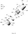
- FIGS. 2A and 2B are exploded perspective views illustrating a needle disc roller apparatus according to an embodiment of the present invention.
- FIG. 3 is a cross-sectional view illustrating the needle disc roller apparatus shown in FIGS. 1 , 2A and 2B .
- FIG. 4 is a perspective view illustrating a needle disc roller.
- FIG. 5 is an exploded perspective view illustrating a needle disc roller.
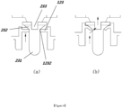
- FIG. 6 is a view illustrating an action of a drug delivery mechanism of a needle disc roller apparatus according to an embodiment of the present invention.
- a needle disc roller apparatus 1 is used in combination with the front end of a drug container 2 having an opening.
- the needle disc roller apparatus 1 includes a viscoelastic connection cap 12 coupled to cover the front end opening of the drug container 2, a roller guiding holder 14 coupled to the front end of the viscoelastic connection cap 12, a needle disc roller 20 maintained so as to be movable forward and backward in the roller guiding holder 14, and a drug delivery mechanism for delivering a drug in the drug container 2 to the needle disc 26 of the needle disc roller 20 when pressurizing the needle disc roller 20 against the skin.
- the needle disc roller apparatus 1 may further include a connection ring 13 for a more reliable assembly between the viscoelastic connection cap 12 and the roller guiding holder 14.
- the drug container 2 stores a drug in a general form of medicine bottle.
- This drug may be various kinds of drugs that may help the needling procedure of punching a plurality of fine holes in the skin.
- the drug container 2 includes a ring-shaped stopping protrusion 2a protruding in a radial direction on the outer circumferential surface of the front end opening. The stopping protrusion 2a is used for one-touch coupling with the viscoelastic connection cap 12, which will be described in detail below.
- the viscoelastic connection cap 12 as a part of the needle disc roller apparatus 1, allows the needle disc roller apparatus 1 to be reliably assembled to the drug container 2 in a sealed state. Also, the viscoelastic connection cap 12 is configured to be detachably coupled to the drug container 2 in a one-touch manner, and to be detachably coupled to the roller guiding holder 14.
- the viscoelastic connection cap 12 is formed of a silicone material that is a viscoelastic material capable of enhancing the assembling property with the drug container 2 and the assembling property with the roller guiding holder 14, and capable of improving the elastic expandability and contractibility of the valve hole which will be described in detail below.
- the viscoelastic connection cap 12 includes a rear outer tube 120a having a circular inner circumference that is closely adhered to the outer circumferential surface of the front end opening of the drug container 2 when being coupled to the front end of the drug container 2, a rear outer tube 120b having a circular outer circumference that is inserted into the opening of the drug container 2 and is closely adhered to the inner circumferential surface of the opening thereof, a plate-shaped ring 120c connecting the inner circumference of the front end of the rear outer tube 120a and the outer circumference of the front end of the rear inner tube 120b, a front outer tube 121 closely adhered to the outer surface of a rear end step 140 of the roller guiding holder 14 when being coupled to the rear end of the roller guiding holder 14, and a front inner tube 128 having a concentric axis and formed inside the front outer tube 121.
- the viscoelastic connection cap 12 integrally includes a hook 122 that is formed so as to direct to the inside from the rear end of the rear outer tube 120a and thus hooked at the stopping protrusion 2a of the drug container 2 in a one-touch manner when being assembled with the viscoelastic connection cap 12 and the drug container 2.
- the outer tube 120a of the drug container 2 is expanded and elastically deformed in a radial direction.
- the coupling is completed, the outer tube 120a is restored to its original state, and the hook 122 is hooked at the stopping protrusion 2a of the drug container 2.
- one-touch fixing of the viscoelastic connection cap 14 is completed.
- the viscoelastic connection cap 12 includes a ring-shaped retaining cover 121a extending inward from the front end of the front outer casing 121.
- the ring-shaped retaining cover 121a as a part of the viscoelastic connection cap 12, has viscoelasticity, and thus is elastically deformed such that the rear end step 140 of the roller guiding holder 14 is inserted into the inside thereof.
- the ring-shaped retaining cover 121a is closely adhered to the front surface of the rear end step 140 and tightly fixes the roller guiding holder 14 to the viscoelastic connection cap 12 in a sealed state.
- the viscoelastic connection cap 12 integrally includes a valve membrane 123 integrally formed in the inside of the hollow of the front inner tube 128.
- the valve membrane 123 has a valve hole 1232 at the center thereof, and allows the valve hole 1232 to be elastically expanded or contracted by an external force due to the characteristics of a viscoelastic material, especially, silicone material.
- the valve membrane 123 with the valve hole 1232 constitutes one drug delivery mechanism together with a valve operating part 23 provided on the needle disc roller 20.
- the valve operating part 23 opens and closes the valve hole 1232 by interacting with the valve membrane 123 as the needle disc roller 20 moves forward or backward.
- the rear inner tube 120b of the viscoelastic connection cap 12 is formed to have a diameter such that the entire outer circumference thereof can be closely inserted into the opening of the drug container 2 without any gap. Accordingly, when the viscoelastic connection cap 12 is coupled to the drug container 2, the rear inner tube 120 makes complete contact with the inner circumferential surface of the opening of the drug container 2 to prevent a drug from leaking.
- the roller guiding holder 14 is a hollow cylindrical structure having front and rear sides opened.
- the roller guiding holder 14 allows the needle disc roller 20 to be movable forward and backward when the needle disc roller 20 is fitted in the hollow of the roller guiding holder 14.
- the roller guiding holder 14 is provided with a pair of guide grooves 142 guiding the forward and backward linear motion of the needle disc roller 20.
- the pair of guide grooves 142 is provided so as to face each other on the inner circumferential surface of the roller guiding holder 14.
- the needle guiding holder 14 includes a front end stopper 143 to prevent the needle guide roller 20 from separating from the front end of the guide groove 142.
- the needle disc roller 20 is held by the roller guiding holder 14 so as to be linearly movable backward and forward.
- the needle disc roller 20 includes a roller bracket 22 installed to be rectilinearly movable forward and backward along the guide groove 142, a core rotation shaft 21 rotatably installed for the roller bracket 22, a roller bobbin 24 rotatably installed for the core rotation shaft 21, and a plurality of ring-shaped needle discs 26 and a plurality of ring-shaped spacers 28 that are all restrained by the roller bobbin 24 and rotate about the core rotation shaft 21 together with the roller bobbin 24.
- the roller bobbin 24 includes a hollow rotation shaft 241 rotatably installed on the outer circumferential surface of the core rotation shaft 21 so as to be rotatable about the core rotation shaft 21, and a pair of bobbin covers 242a and 242b provided at both ends of the hollow rotation shaft 241 to prevent separation of a disc-spacer set including the plurality of ring-shaped needle discs 26 and the plurality of ring-shaped spacers 28.
- at least one bobbin cover 242b of the pair of bobbin covers 242a and 242b may be detachably assembled to the hollow rotation shaft 241 so as to facilitate assembly and separation of the ring-shaped needle discs 26 and ring-shaped spacers 28.
- the plurality of ring-shaped needle discs 26 and the plurality of ring-shaped spacers 28 may be restrained by the hollow rotation shaft 241 and may be integrally rotated although the plurality of ring-shaped needle discs 26 and the plurality of ring-shaped spacers 28 are assembled in a separated state.
- a key groove 2412 formed on the outer circumferential surface of the hollow rotation shaft 241 in a longitudinal direction, and first keys 265 formed on the inner circumferential surfaces of the respective needle discs 26 and the second keys 285 formed on the inner circumferential surfaces of the respective spacers 28 are provided.
- Each of the plurality of needle discs 26 includes a plurality of sawtooth-shaped needles 262 at a certain interval along the outer circumference thereof. Also, a drug delivery groove 263 is formed between neighboring needles 262.
- the pair of bobbin covers 242a and 242b includes a first bobbin cover 242a integrated with the hollow shaft 241 and a second bobbin cover 242b assembled with the first bobbin cover 242a.
- the ring-shaped needle discs 26 and the ring-shaped spacers 28 may be mounted onto or separated from the outer circumferential surface of the hollow rotation shaft 241.
- the ring-shaped needle discs 26 and the ring-shaped spacers 28 are alternately arranged on the outer circumferential surface of the hollow rotation shaft 241.
- the rectangular first keys 265 formed on the ring-shaped needle discs 26 and the rectangular second keys 285 formed on the ring-shaped spacers 28 may be fitted in the key groove 2412 formed on the outer circumferential surface of the hollow rotation shaft 241 in a row.
- the ring-shaped needle discs 26 and the ring-shaped spacers 28 may be restrained by the hollow rotation shaft 26 and may be integrally rotated.
- the needle disc roller 20 may be manufactured by replacing only the corresponding needle discs.
- the roller bracket 22 includes a base portion 221 and a pair of shaft mounting walls 222 and 222 vertically formed on both sides of the front surface of the base portion 221. Also, shaft holes 2224 and 2224 in which the core rotation shaft 21 is rotatably fitted are formed in the pair of shaft mounting walls 222. Each of the pair of shaft mounting walls 222 is slidably fitted in the guide groove 142 (see FIGS. 1 to 3 ) of the roller guiding holder 14 described above.
- the valve operating part 23 constituting a part of the drug delivery mechanism is formed on the rear surface of the base portion 221.
- the valve operating part 23 includes a rod portion 231 perpendicular to the base portion 221 and longitudinally extended from the center of the rear surface of the base portion 221, and a tapered pressing portion 232 formed on the outer circumferential surface of the rod portion 231.
- the rod portion 231 is fitted into the circular valve hole 1232 formed in the valve membrane 123 in a sealed state without forming a fine gap, and moves forward and backward together with the forward and backward movement of the needle disc roller 20.
- the tapered pressing portion 232 is formed in the middle of the rod portion 231, and has a shape gradually increasing in diameter from the rear end having the same diameter as the rod portion 231 toward the front end having a diameter larger than the diameter of the rod portion 231.
- the size of the valve hole 1232 formed in the valve membrane 123 is expanded in accordance with the increase of the diameter of the tapered pressing portion 232.
- a drug passage incision groove 233 is formed from the outer side of the tapered pressing portion 232 having a largest diameter to the inner side of the tapered pressing portion 232 having a smallest diameter.
- the drug passage incision groove 233 allows a drug to pass therethrough while the tapered pressing portion 232 is pressing the valve hole 1232.
- the drug passage incision groove 233 is not formed in the tapered pressing portion 232, even if the tapered pressing portion 232 presses the valve membrane 123 to expand the valve hole 1232, the valve hole 123 is blocked by the tapered pressing portion 232, resulting in failure of passage of the drug.
- a part of the valve hole 1232 expanded is connected to the drug passage incision groove 233 to allow the drug to pass therethrough.
- the tapered pressing portion 232 has a pair of drug passage incision grooves 233 most adjacently to the outer circumference of the needle disc-spacer set, and the pair of drug passage incision grooves 233 are formed at positions opposed to each other so as to smoothly supply the drug regardless of the clockwise or counterclockwise direction of the needle disc 26. More specifically, the pair of drug passage incision grooves 233 is formed in a form of bisecting the tapered pressing portion 232 in parallel with the needle disc 26.
- FIG. 6 is a view illustrating an action of a drug delivery mechanism of a needle disc roller apparatus according to an embodiment of the present invention.
- the rod portion 231 is inserted into the valve hole 1232 formed in the valve membrane 123 in a sealed state to prevent from leaking from the drug container.
- the valve membrane 123 is not pressurized. Accordingly, the valve hole 1232 formed in the valve membrane 123 is not elastically expanded.
- the rod portion 231 and the tapered pressing portion 232 moves backward as shown in FIG. 6B to push back and deform the valve membrane 123 and simultaneously expand the valve hole 1232. Since the tapered pressing portion 232 is fitted into the valve hole 1232 while expanding the valve hole 1232, the valve hole 1232 is opened through the drug passage incision groove 233 formed on the tapered pressing portion 232. Accordingly, a drug stored in the drug container is supplied from the drug container to the needle disc of the disc roller through the valve hole 1232 and the drug passage incision groove 233.
Landscapes
- Health & Medical Sciences (AREA)
- Life Sciences & Earth Sciences (AREA)
- Engineering & Computer Science (AREA)
- Veterinary Medicine (AREA)
- Public Health (AREA)
- General Health & Medical Sciences (AREA)
- Animal Behavior & Ethology (AREA)
- Heart & Thoracic Surgery (AREA)
- Biomedical Technology (AREA)
- Hematology (AREA)
- Anesthesiology (AREA)
- Epidemiology (AREA)
- Pain & Pain Management (AREA)
- Physical Education & Sports Medicine (AREA)
- Rehabilitation Therapy (AREA)
- Medical Informatics (AREA)
- Dermatology (AREA)
- Pulmonology (AREA)
- Bioinformatics & Cheminformatics (AREA)
- Infusion, Injection, And Reservoir Apparatuses (AREA)
- Media Introduction/Drainage Providing Device (AREA)
Claims (14)
- Nadelscheibenrollenvorrichtung mit:einer Verbindungskappe (12),einem Rollenführungshalter (14), der mit einem vorderen Ende der Verbindungskappe (12) gekoppelt ist, undeiner Nadelscheibenrolle (20),wobei die Nadelscheibenrolle (20) aufweist:einen Rollenhalter (22);eine Kerndrehwelle (21), die drehbar in den Rollenbügel (22) eingebaut ist, eine Rollenspule (24), die mit der Kerndrehwelle (21) drehbar eingebaut ist, undmehrere ringförmige Nadelscheiben (26) und mehrere ringförmige Abstandhalter (28), die sämtlich durch die Rollenspule (24) gehalten sind und zusammen mit der Rollenspule (24) um die Kerndrehwelle (21) drehen,wobei der Rollenbügel (22) aufweist:einen Basisbereich (221); undzwei Wellenbefestigungswände (222 und 222), die vertikal auf beiden Seiten der Vorderfläche des Basisbereichs ausgebildet sind, undwobei die beiden Wellenbefestigungswände (222) Wellenlöcher (2224 und 2224) aufweisen, in welche die Kerndrehwelle (21) drehbar eingesetzt ist, dadurch gekennzeichnet,dass die Nadelscheibenrolle vorwärts und rückwärts bewegbar in dem Rollenführungshalter (14) gehalten ist;dass der Rollenbügel (22) entlang einer Führungsnut (142) geradlinig vorwärts und rückwärts bewegbar eingebaut ist, wobei jede der beiden Wellenbefestigungswände (222) gleitend bewegbar in die Führungsnut (142) eingesetzt ist;dass die Nadelscheibenrolle ferner einen Medikamentenabgabemechanismus aufweist, welcher in Reaktion auf das Vor- und Zurückbewegen der Nadelscheibenrolle (20) ein in einem Medikamentenbehälter befindliche Medikament an die ringförmigen Nadelscheiben (26) der Nadelscheibenrolle (20) abgibt, während die Nadelscheibenrolle (20) gegen die Haut gedrückt wird.
- Nadelscheibenrollenvorrichtung nach Anspruch 1, bei welcher die Rollenspule (24) aufweist:eine hohle Drehwelle (241), die auf der Außenumfangsfläche der Kerndrehwelle (21) derart drehbar angebracht ist, dass sie um die Kerndrehwelle (21) drehbar ist; undzwei Spulenabdeckungen (242a und 242b), die an beiden Enden der hohlen Drehwelle (241) vorgesehen sind, um ein Lösen der mehreren ringförmigen Nadelscheiben (26) und der mehreren ringförmigen Abstandhalter (28) zu verhindern.
- Nadelscheibenrollenvorrichtung nach Anspruch 2, bei welcher mindestens eine Spulenabdeckung (242b) der beiden Spulenabdeckung (242a und 242b) in Bezug auf die hohle Drehwelle (241) lösbar montiert ist.
- Nadelscheibenrollenvorrichtung nach Anspruch 2, bei welcher mindestens eine Passfedernut (2412) in Längsrichtung in der Außenumfangsfläche der hohlen Drehwelle (241) ausgebildet ist, jede der mehreren ringförmigen Nadelscheiben (26) eine erste Passfeder (265) auf einer Innenfläche derselben zum Einsetzen in die Passfedernut (2412) aufweist, jeder der mehreren ringförmigen Abstandhalter eine zweite Passfeder auf einer Innenumfangsfläche desselben zum Einsetzen in die Passfedernut (2412) aufweist, und die mehreren ringförmigen Nadelscheiben (26) und die mehreren ringförmigen Abstandhalter (28) durch die hohle Drehwelle (241) durch Einsetzen der ersten Passfeder (265) und der zweiten Passfeder (285) der mehreren ringförmigen Nadelscheiben (26) und der mehreren ringförmigen Abstandhalter (28) in einer Reihe in die Passfedernut (2412) zurückgehalten sind.
- Nadelscheibenrollenvorrichtung nach Anspruch 1, dadurch gekennzeichnet, dass der Medikamentenabgabemechanismus aufweist:eine Ventilmembran (123) aus einem viskoelastischen Material mit einem Ventilloch (1232), das in der Verbindungskappe (12) ausgebildet ist und mit einer Vorderendöffnung des Medikamentenbehälters verbunden ist; undein Ventilbetätigungsteil (23), welches das Ventilloch (1232) wahlweise öffnet und schließt, indem es sich zusammen mit der Nadelscheibenrolle (20) vorwärts und rückwärts bewegt; undwobei das Ventilbetätigungsteil (23) aufweist:einen Stabbereich (231), der sich einstückig mit der Nadelscheibenrolle (20) vorwärts und rückwärts bewegt, wobei er spaltfrei in den Ventilloch (1232) eingesetzt ist;einen sich verjüngenden Pressbereich (232), der in der Mitte des Stabbereichs (231) ausgebildet ist und das Ventilloch (1232) elastisch aufweitet, indem er in das Ventilloch (1232) eingeführt wird, während er sich zusammen mit dem Stabbereich (231) zurückbewegt; undmindestens eine Medikamentendurchlasseinschnittrille (233), die in dem sich verjüngenden Pressbereich (232) gebildet ist und mit dem Ventilloch (1232) verbunden ist, um das Ventilloch (1232) zu öffnen, wenn das Ventilloch (1232) durch den sich verjüngenden Pressbereich (232) aufgeweitet ist.
- Nadelscheibenrollenvorrichtung nach Anspruch 1, dadurch gekennzeichnet,dass die Verbindungskappe (12) aus viskoelastischem Material besteht und zum Abdecken einer Vorderendöffnung des Medikamentenbehälters (2) verbunden ist,dadurch gekennzeichnet, dass der Medikamentenabgabemechanismus aufweist:eine Ventilmembran (123) aus einem viskoelastischen Material mit einem Ventilloch (1232), das in der viskoelastischen Verbindungskappe (12) ausgebildet ist und mit einer Vorderendöffnung des Medikamentenbehälters verbunden ist; undein Ventilbetätigungsteil (23), welches das Ventilloch (1232) wahlweise öffnet und schließt, indem es sich zusammen mit der Nadelscheibenrolle (20) vorwärts und rückwärts bewegt; undwobei das Ventilbetätigungsteil (23) aufweist:einen Stabbereich (231), der sich einstückig mit der Nadelscheibenrolle (20) vorwärts und rückwärts bewegt, wobei er spaltfrei in den Ventilloch (1232) eingeführt wird;einen sich verjüngenden Pressbereich (232), der in der Mitte des Stabbereichs (231) ausgebildet ist und das Ventilloch (1232) elastisch aufweitet, indem er in das Ventilloch (1232) eingeführt wird, während er sich zusammen mit dem Stabbereich (231) zurückbewegt; undmindestens eine Medikamentendurchlasseinschnittrille (233), die in dem sich verjüngenden Pressbereich (232) gebildet ist und mit dem Ventilloch (1232) verbunden ist, um das Ventilloch (1232) zu öffnen, wenn das Ventilloch (1232) durch den sich verjüngenden Pressbereich (232) aufgeweitet ist.
- Nadelscheibenrollenvorrichtung nach Anspruch 6, bei welcher die viskoelastische Verbindungskappe (12) aufweist:ein hinteres äußeres Rohr (120a), das eng an der Außenumfangsfläche der Vorderendöffnung des Medikamentenbehälters (2) anliegt, wenn es mit dem Vorderende des Medikamentenbehälters (2) gekoppelt ist;ein hinteres inneres Rohr (120b), das in eine Öffnung eingesetzt ist und eng an der Innenumfangsfläche der Öffnung anliegt;einen plattenförmigen Ring (120c), der den innenumfang des Vorderendes des hinteren äußeren Rohrs (120a) und den Außenumfang der Vorderendes des hinteren inneren Rohrs (120b) verbindet;ein vorderes äußeres Rohr (121), das eng an der Außenfläche eines Bereichs eines hinteren Endes des Rollenführungshalters anliegt, wenn es mit dem Rollenführungshalter (14) verbunden ist; undein vorderes inneres Rohr (128), das eine konzentrische Achse aufweist und in dem vorderen äußeren Rohr (121) ausgebildet ist.
- Nadelscheibenrollenvorrichtung nach Anspruch 7, bei welcher die Ventilmembran (123) einstückig in dem Hohlraum des vorderen inneren Rohrs (128) ausgebildet ist, und das Ventilloch (1232) in der Mitte der Ventilmembran (123) gebildet ist.
- Nadelscheibenrollenvorrichtung nach Anspruch 6, bei welcher der sich verjüngende Pressbereich (232) eine Form aufweist, die von dem hinteren Ende, das denselben Durchmesser aufweist wie der Stabbereich (231) zum vorderen Ende (231), das einen Durchmesser aufweist, der größer als der Durchmesser des Stabbereichs (231) ist, allmählich zunimmt.
- Nadelscheibenrollenvorrichtung nach Anspruch 9, bei welcher die Medikamentendurchlasseinschnittrille (233) ein Paar mit der auf einer Seite des sich verjüngenden Drückbereichs (232) gebildeten Medikamentendurchlasseinschnittrille (233) bildet, wobei sie auf der anderen Seite des sich verjüngenden Drückbereichs (232) gebildet ist, und die beiden Medikamentendurchlasseinschnittrillen (233 und 233) nahe dem Außenumfang der Nadelscheibe (26) und einander gegenüberliegend gebildet sind.
- Nadelscheibenrollenvorrichtung nach Anspruch 1, dadurch gekennzeichnet,dass die Verbindungskappe (12) aus viskoelastischem Material besteht und zum Abdecken einer Vorderendöffnung des Medikamentenbehälters (2) verbunden ist; unddadurch gekennzeichnet, dass die Verbindungskappe (12) aufweist:ein hinteres äußeres Rohr (120a) mit einem kreisförmigen Innenumfang, das eng an der Außenumfangsfläche der Vorderendöffnung des Medikamentenbehälters (2) anliegt, wenn es mit dem Vorderende des Medikamentenbehälters (2) gekoppelt ist;ein hinteres inneres Rohr (120b) mit einem kreisförmigen Außenumfang, das in die Öffnung des Medikamentenbehälters (2) eingesetzt ist und eng an der Innenumfangsfläche der Öffnung desselben anliegt;einen plattenförmigen Ring (120c), der den innenumfang des Vorderendes des hinteren äußeren Rohrs (120a) und den Außenumfang der Vorderendes des hinteren inneren Rohrs (120b) verbindet;ein vorderes äußeres Rohr (121), das eng an der Außenfläche einer hinteren Endstufe (140) des Rollenführungshalters (14) anliegt, wenn es mit dem hinteren Ende des Rollenführungshalters (14) verbunden ist; undein vorderes inneres Rohr (128), das eine konzentrische Achse aufweist und in dem vorderen äußeren Rohr (121) ausgebildet ist;ein Haken (122), der derart ausgebildet ist, dass er von dem inneren Ende des hinteren äußeren Rohrs (120a) nach innen gerichtet ist, und somit auf One-Touch-Weise mit einem Stoppvorsprung (2a) des Medikamentenbehälters (2) verhakt wird, wenn er mit der viskoelastischen Verbindungskappe (12) und dem Medikamentenbehälter (2) zusammengesetzt wird; undeine ringförmige Rückhalteabdeckung (121a), die sich von dem vorderen Ende des vorderen äußeren Gehäuses (121) nach innen erstreckt und derart elastisch verformt ist, dass eine hintere Endstufe (140) des Rollenführungshalters (14) in das Innere derselben eingesetzt ist.
- Nadelscheibenrollenvorrichtung nach Anspruch 11, bei welcher eine Ventilmembran (123) einstückig in dem Hohlraum des vorderen inneren Rohrteils (128) gebildet ist, die Ventilmembran (123) ein Ventilloch (1223) in deren Mitte aufweist, und das Ventilloch (1232) durch eine externe Kraft elastisch aufgeweitet oder zusammengezogen wird.
- Nadelscheibenrollenvorrichtung nach Anspruch 12, bei welcher der Medikamentenausgabemechanismus ein Ventilöffnungsteil (23) aufweist, das zusammen mit der Ventilmembran (123) an der Nadelscheibenroll (20) vorgesehen ist, und das Ventilöffnungsteil (23) mit der Ventilmembran (123) gemäß der Vorwärts- und Rückwärtsbewegung der Ventilscheibe (12) zusammenwirkt, um das Ventilloch (1232) zu öffnen oder zu schließen.
- Nadelscheibenrollenvorrichtung nach Anspruch 13, bei welcher das Ventilbetätigungsteil aufweist:einen Stabbereich, der sich mit der Nadelscheibenrolle (20) vorwärts und rückwärts bewegt, wobei er spaltfrei in den Ventilloch (1232) eingesetzt ist;einen sich verjüngenden Pressbereich (232), der in der Mitte des Stabbereichs (231) ausgebildet ist und eine Form aufweist, die von dem hinteren Ende, das denselben Durchmesser aufweist wie der Stabbereich (231) zum vorderen Ende (231), das einen Durchmesser aufweist, der größer als der Durchmesser des Stabbereichs (231) ist, allmählich zunimmt; undeine in dem sich verjüngenden Drückbereich (232) ausgebildete Medikamentendurchlasseinschnittrille (233),wobei, wenn sich der Stabbereich (231) rückwärts bewegt und der sich verjüngende Drückbereich (232) gegen die Ventilmembran (123) drückt, die Ventilmembran (123) von dem sich verjüngenden Drückbereich (232) gedrückt wird, um das Ventilloch (1232) aufzuweiten, und das Ventilloch (1232) mit der Medikamentendurchlasseinschnittrille (233) verbunden wird und geöffnet wird, während es durch den sich verjüngenden Drückbereich (232) aufgeweitet ist.
Applications Claiming Priority (4)
| Application Number | Priority Date | Filing Date | Title |
|---|---|---|---|
| KR1020160117175A KR101682863B1 (ko) | 2016-09-12 | 2016-09-12 | 가압 개방식 약물 전달 기구를 갖는 니들 디스크 롤러 장치 |
| KR1020160117193A KR101700563B1 (ko) | 2016-09-12 | 2016-09-12 | 양방형 접속 구조를 갖는 점탄성 연결캡을 포함하는 니들 디스크 롤러 장치 |
| KR1020160117166A KR101701097B1 (ko) | 2016-09-12 | 2016-09-12 | 동축 이중 회전형 니들 디스크 롤러 장치 |
| PCT/KR2017/008225 WO2018048099A1 (ko) | 2016-09-12 | 2017-07-31 | 니들 디스크 롤러 장치 |
Publications (3)
| Publication Number | Publication Date |
|---|---|
| EP3511048A1 EP3511048A1 (de) | 2019-07-17 |
| EP3511048A4 EP3511048A4 (de) | 2020-05-20 |
| EP3511048B1 true EP3511048B1 (de) | 2024-11-27 |
Family
ID=61561870
Family Applications (1)
| Application Number | Title | Priority Date | Filing Date |
|---|---|---|---|
| EP17848983.7A Active EP3511048B1 (de) | 2016-09-12 | 2017-07-31 | Nadelscheibenwalzvorrichtung |
Country Status (4)
| Country | Link |
|---|---|
| EP (1) | EP3511048B1 (de) |
| CN (1) | CN108778397B (de) |
| ES (1) | ES2997369T3 (de) |
| WO (1) | WO2018048099A1 (de) |
Families Citing this family (2)
| Publication number | Priority date | Publication date | Assignee | Title |
|---|---|---|---|---|
| WO2023236765A1 (zh) * | 2022-06-08 | 2023-12-14 | 苏州纳生微电子有限公司 | 微针滚轮和容器 |
| CN120000939B (zh) * | 2025-04-22 | 2025-07-11 | 山东同齐医学科技有限公司 | 一种防刮肉皮肤滚针 |
Family Cites Families (16)
| Publication number | Priority date | Publication date | Assignee | Title |
|---|---|---|---|---|
| KR100873221B1 (ko) * | 2008-06-02 | 2008-12-10 | 주식회사 제이앤엘 | 마이크로니들 롤러구조체 |
| CN201231007Y (zh) * | 2008-07-23 | 2009-05-06 | 冯来坤 | 一种美容用简易滚轮式微针导入器 |
| CN101670145B (zh) * | 2009-09-01 | 2012-06-06 | 陈德锋 | 美容仪 |
| KR101157739B1 (ko) * | 2010-03-12 | 2012-06-25 | 이명인 | 쇼버형 니들 롤러 |
| KR101208440B1 (ko) * | 2010-06-01 | 2012-12-10 | (주)에스엔피월드 | 롤러부가 구비된 액상도포장치 |
| US9227021B2 (en) * | 2010-06-29 | 2016-01-05 | Genesis Biosystems, Inc. | Microneedle roller (MNR) infusion system |
| US9616211B2 (en) * | 2011-11-21 | 2017-04-11 | New Permanent Makeup Ltd. | Roller device |
| EP2774594B1 (de) * | 2011-12-08 | 2019-08-07 | King Saud University | Vorrichtung zur transdermalen Abgabe einer bioaktiven Lösung |
| KR101182494B1 (ko) * | 2012-02-20 | 2012-09-12 | 윤니나 | 다수 개의 니들들을 포함하는 니들 롤러 및 이에 사용되는 디스크의 제조방법 |
| KR20140044098A (ko) * | 2012-10-04 | 2014-04-14 | 공광열 | 마이크로니들 롤러 |
| KR101573252B1 (ko) * | 2015-09-11 | 2015-12-11 | 윤형 | 이미용기구 |
| KR101584703B1 (ko) * | 2015-09-18 | 2016-01-12 | 주식회사 지엠홀딩스 | 피부 및 탈모 치료용 이미용기기 |
| KR101647009B1 (ko) * | 2016-03-29 | 2016-08-23 | 윤형 | 이미용기구 |
| KR101682863B1 (ko) * | 2016-09-12 | 2016-12-06 | 이창우 | 가압 개방식 약물 전달 기구를 갖는 니들 디스크 롤러 장치 |
| KR101700563B1 (ko) * | 2016-09-12 | 2017-01-31 | 이창우 | 양방형 접속 구조를 갖는 점탄성 연결캡을 포함하는 니들 디스크 롤러 장치 |
| KR101701097B1 (ko) * | 2016-09-12 | 2017-02-14 | 이창우 | 동축 이중 회전형 니들 디스크 롤러 장치 |
-
2017
- 2017-07-31 WO PCT/KR2017/008225 patent/WO2018048099A1/ko not_active Ceased
- 2017-07-31 CN CN201780016681.2A patent/CN108778397B/zh active Active
- 2017-07-31 ES ES17848983T patent/ES2997369T3/es active Active
- 2017-07-31 EP EP17848983.7A patent/EP3511048B1/de active Active
Also Published As
| Publication number | Publication date |
|---|---|
| CN108778397B (zh) | 2020-10-16 |
| EP3511048A1 (de) | 2019-07-17 |
| WO2018048099A1 (ko) | 2018-03-15 |
| ES2997369T3 (en) | 2025-02-17 |
| EP3511048A4 (de) | 2020-05-20 |
| CN108778397A (zh) | 2018-11-09 |
Similar Documents
| Publication | Publication Date | Title |
|---|---|---|
| KR101682863B1 (ko) | 가압 개방식 약물 전달 기구를 갖는 니들 디스크 롤러 장치 | |
| CN108778396B (zh) | 包括瓶颈下端紧贴结构的粘弹性连接盖的微针滚轮装置 | |
| KR102399468B1 (ko) | 약물 전달 장치용 투여 조립체 및 이를 포함하는 약물 전달 장치 | |
| US10898646B2 (en) | Container holder assembly | |
| JP6566964B2 (ja) | 経皮的薬物送達装置および方法 | |
| KR102414648B1 (ko) | 약물 전달 장치용 투여 조립체 및 이를 포함하는 약물 전달 장치 | |
| EP2865401B1 (de) | Instrument zum betrieb eines fluidinjektors mit einer multimikronadelvorrichtung | |
| JP6561069B2 (ja) | 経皮的薬物送達装置のレセプタクル部分および方法 | |
| EP3511048B1 (de) | Nadelscheibenwalzvorrichtung | |
| US10926072B2 (en) | Operation tool for fluid injector using multi microneedle device | |
| KR20150037745A (ko) | 멀티 마이크로니들 디바이스 사용 유체 주입기 조작 기구 | |
| US20180028744A1 (en) | Medical fluid injector and medical fluid supply device including same | |
| JP2004245217A (ja) | 体積流を手動で発生させる吐出装置 | |
| CN211175578U (zh) | 磁转子组件及电子膨胀阀 | |
| JP2017516513A (ja) | 経皮的薬物送達装置のコントローラ部分および方法 | |
| EP3490646B1 (de) | Medikamentenbehälteranordnung für eine medikamentenabgabevorrichtung | |
| US20170296751A1 (en) | Cartridge Retainer for an Injection Device | |
| KR101701097B1 (ko) | 동축 이중 회전형 니들 디스크 롤러 장치 | |
| KR101700563B1 (ko) | 양방형 접속 구조를 갖는 점탄성 연결캡을 포함하는 니들 디스크 롤러 장치 | |
| JP2015533530A (ja) | 2段式のトリガを有する使い捨て注射器 | |
| JP4717438B2 (ja) | 医療用の製品を注入するためのデバイス | |
| JP2021508588A (ja) | 解除可能に連結されたピペットチップをロックするための、電磁的に駆動可能なロックアクチュエータを有するピペット装置 | |
| EP3643959A1 (de) | Sicherheitsventil für eine gasflasche und gasflasche mit solch einem ventil | |
| US9245701B2 (en) | Pressure switch for a motor vehicle | |
| EP3117818A1 (de) | Massagevorrichtung |
Legal Events
| Date | Code | Title | Description |
|---|---|---|---|
| STAA | Information on the status of an ep patent application or granted ep patent |
Free format text: STATUS: THE INTERNATIONAL PUBLICATION HAS BEEN MADE |
|
| PUAI | Public reference made under article 153(3) epc to a published international application that has entered the european phase |
Free format text: ORIGINAL CODE: 0009012 |
|
| STAA | Information on the status of an ep patent application or granted ep patent |
Free format text: STATUS: REQUEST FOR EXAMINATION WAS MADE |
|
| 17P | Request for examination filed |
Effective date: 20190408 |
|
| AK | Designated contracting states |
Kind code of ref document: A1 Designated state(s): AL AT BE BG CH CY CZ DE DK EE ES FI FR GB GR HR HU IE IS IT LI LT LU LV MC MK MT NL NO PL PT RO RS SE SI SK SM TR |
|
| AX | Request for extension of the european patent |
Extension state: BA ME |
|
| DAV | Request for validation of the european patent (deleted) | ||
| DAX | Request for extension of the european patent (deleted) | ||
| RAP1 | Party data changed (applicant data changed or rights of an application transferred) |
Owner name: K.L GLOBAL CO., LTD. |
|
| RIN1 | Information on inventor provided before grant (corrected) |
Inventor name: YI, CHANGWOO |
|
| RIN1 | Information on inventor provided before grant (corrected) |
Inventor name: LEE, CHANGWOO |
|
| A4 | Supplementary search report drawn up and despatched |
Effective date: 20200421 |
|
| RIC1 | Information provided on ipc code assigned before grant |
Ipc: A61M 37/00 20060101AFI20200415BHEP |
|
| REG | Reference to a national code |
Ref country code: DE Ref legal event code: R079 Free format text: PREVIOUS MAIN CLASS: A61M0037000000 Ipc: A61M0039220000 Ref country code: DE Ref legal event code: R079 Ref document number: 602017086440 Country of ref document: DE Free format text: PREVIOUS MAIN CLASS: A61M0037000000 Ipc: A61M0039220000 |
|
| GRAP | Despatch of communication of intention to grant a patent |
Free format text: ORIGINAL CODE: EPIDOSNIGR1 |
|
| STAA | Information on the status of an ep patent application or granted ep patent |
Free format text: STATUS: GRANT OF PATENT IS INTENDED |
|
| RIC1 | Information provided on ipc code assigned before grant |
Ipc: A61M 37/00 20060101ALI20240523BHEP Ipc: A61H 15/02 20060101ALI20240523BHEP Ipc: A61H 15/00 20060101ALI20240523BHEP Ipc: A61M 39/22 20060101AFI20240523BHEP |
|
| INTG | Intention to grant announced |
Effective date: 20240619 |
|
| GRAS | Grant fee paid |
Free format text: ORIGINAL CODE: EPIDOSNIGR3 |
|
| GRAA | (expected) grant |
Free format text: ORIGINAL CODE: 0009210 |
|
| STAA | Information on the status of an ep patent application or granted ep patent |
Free format text: STATUS: THE PATENT HAS BEEN GRANTED |
|
| AK | Designated contracting states |
Kind code of ref document: B1 Designated state(s): AL AT BE BG CH CY CZ DE DK EE ES FI FR GB GR HR HU IE IS IT LI LT LU LV MC MK MT NL NO PL PT RO RS SE SI SK SM TR |
|
| REG | Reference to a national code |
Ref country code: GB Ref legal event code: FG4D |
|
| REG | Reference to a national code |
Ref country code: CH Ref legal event code: EP |
|
| REG | Reference to a national code |
Ref country code: IE Ref legal event code: FG4D |
|
| REG | Reference to a national code |
Ref country code: DE Ref legal event code: R096 Ref document number: 602017086440 Country of ref document: DE |
|
| REG | Reference to a national code |
Ref country code: ES Ref legal event code: FG2A Ref document number: 2997369 Country of ref document: ES Kind code of ref document: T3 Effective date: 20250217 |
|
| REG | Reference to a national code |
Ref country code: LT Ref legal event code: MG9D |
|
| REG | Reference to a national code |
Ref country code: NL Ref legal event code: MP Effective date: 20241127 |
|
| PG25 | Lapsed in a contracting state [announced via postgrant information from national office to epo] |
Ref country code: IS Free format text: LAPSE BECAUSE OF FAILURE TO SUBMIT A TRANSLATION OF THE DESCRIPTION OR TO PAY THE FEE WITHIN THE PRESCRIBED TIME-LIMIT Effective date: 20250327 Ref country code: HR Free format text: LAPSE BECAUSE OF FAILURE TO SUBMIT A TRANSLATION OF THE DESCRIPTION OR TO PAY THE FEE WITHIN THE PRESCRIBED TIME-LIMIT Effective date: 20241127 Ref country code: PT Free format text: LAPSE BECAUSE OF FAILURE TO SUBMIT A TRANSLATION OF THE DESCRIPTION OR TO PAY THE FEE WITHIN THE PRESCRIBED TIME-LIMIT Effective date: 20250327 |
|
| PG25 | Lapsed in a contracting state [announced via postgrant information from national office to epo] |
Ref country code: FI Free format text: LAPSE BECAUSE OF FAILURE TO SUBMIT A TRANSLATION OF THE DESCRIPTION OR TO PAY THE FEE WITHIN THE PRESCRIBED TIME-LIMIT Effective date: 20241127 Ref country code: NL Free format text: LAPSE BECAUSE OF FAILURE TO SUBMIT A TRANSLATION OF THE DESCRIPTION OR TO PAY THE FEE WITHIN THE PRESCRIBED TIME-LIMIT Effective date: 20241127 |
|
| REG | Reference to a national code |
Ref country code: AT Ref legal event code: MK05 Ref document number: 1745148 Country of ref document: AT Kind code of ref document: T Effective date: 20241127 |
|
| PG25 | Lapsed in a contracting state [announced via postgrant information from national office to epo] |
Ref country code: BG Free format text: LAPSE BECAUSE OF FAILURE TO SUBMIT A TRANSLATION OF THE DESCRIPTION OR TO PAY THE FEE WITHIN THE PRESCRIBED TIME-LIMIT Effective date: 20241127 |
|
| PG25 | Lapsed in a contracting state [announced via postgrant information from national office to epo] |
Ref country code: NO Free format text: LAPSE BECAUSE OF FAILURE TO SUBMIT A TRANSLATION OF THE DESCRIPTION OR TO PAY THE FEE WITHIN THE PRESCRIBED TIME-LIMIT Effective date: 20250227 |
|
| PG25 | Lapsed in a contracting state [announced via postgrant information from national office to epo] |
Ref country code: GR Free format text: LAPSE BECAUSE OF FAILURE TO SUBMIT A TRANSLATION OF THE DESCRIPTION OR TO PAY THE FEE WITHIN THE PRESCRIBED TIME-LIMIT Effective date: 20250228 Ref country code: LV Free format text: LAPSE BECAUSE OF FAILURE TO SUBMIT A TRANSLATION OF THE DESCRIPTION OR TO PAY THE FEE WITHIN THE PRESCRIBED TIME-LIMIT Effective date: 20241127 Ref country code: AT Free format text: LAPSE BECAUSE OF FAILURE TO SUBMIT A TRANSLATION OF THE DESCRIPTION OR TO PAY THE FEE WITHIN THE PRESCRIBED TIME-LIMIT Effective date: 20241127 |
|
| PG25 | Lapsed in a contracting state [announced via postgrant information from national office to epo] |
Ref country code: PL Free format text: LAPSE BECAUSE OF FAILURE TO SUBMIT A TRANSLATION OF THE DESCRIPTION OR TO PAY THE FEE WITHIN THE PRESCRIBED TIME-LIMIT Effective date: 20241127 |
|
| PG25 | Lapsed in a contracting state [announced via postgrant information from national office to epo] |
Ref country code: RS Free format text: LAPSE BECAUSE OF FAILURE TO SUBMIT A TRANSLATION OF THE DESCRIPTION OR TO PAY THE FEE WITHIN THE PRESCRIBED TIME-LIMIT Effective date: 20250227 |
|
| PG25 | Lapsed in a contracting state [announced via postgrant information from national office to epo] |
Ref country code: SM Free format text: LAPSE BECAUSE OF FAILURE TO SUBMIT A TRANSLATION OF THE DESCRIPTION OR TO PAY THE FEE WITHIN THE PRESCRIBED TIME-LIMIT Effective date: 20241127 |
|
| PG25 | Lapsed in a contracting state [announced via postgrant information from national office to epo] |
Ref country code: DK Free format text: LAPSE BECAUSE OF FAILURE TO SUBMIT A TRANSLATION OF THE DESCRIPTION OR TO PAY THE FEE WITHIN THE PRESCRIBED TIME-LIMIT Effective date: 20241127 |
|
| PG25 | Lapsed in a contracting state [announced via postgrant information from national office to epo] |
Ref country code: EE Free format text: LAPSE BECAUSE OF FAILURE TO SUBMIT A TRANSLATION OF THE DESCRIPTION OR TO PAY THE FEE WITHIN THE PRESCRIBED TIME-LIMIT Effective date: 20241127 |
|
| PG25 | Lapsed in a contracting state [announced via postgrant information from national office to epo] |
Ref country code: RO Free format text: LAPSE BECAUSE OF FAILURE TO SUBMIT A TRANSLATION OF THE DESCRIPTION OR TO PAY THE FEE WITHIN THE PRESCRIBED TIME-LIMIT Effective date: 20241127 |
|
| PG25 | Lapsed in a contracting state [announced via postgrant information from national office to epo] |
Ref country code: SK Free format text: LAPSE BECAUSE OF FAILURE TO SUBMIT A TRANSLATION OF THE DESCRIPTION OR TO PAY THE FEE WITHIN THE PRESCRIBED TIME-LIMIT Effective date: 20241127 |
|
| PG25 | Lapsed in a contracting state [announced via postgrant information from national office to epo] |
Ref country code: CZ Free format text: LAPSE BECAUSE OF FAILURE TO SUBMIT A TRANSLATION OF THE DESCRIPTION OR TO PAY THE FEE WITHIN THE PRESCRIBED TIME-LIMIT Effective date: 20241127 |
|
| REG | Reference to a national code |
Ref country code: DE Ref legal event code: R097 Ref document number: 602017086440 Country of ref document: DE |
|
| PG25 | Lapsed in a contracting state [announced via postgrant information from national office to epo] |
Ref country code: SE Free format text: LAPSE BECAUSE OF FAILURE TO SUBMIT A TRANSLATION OF THE DESCRIPTION OR TO PAY THE FEE WITHIN THE PRESCRIBED TIME-LIMIT Effective date: 20241127 |
|
| PLBE | No opposition filed within time limit |
Free format text: ORIGINAL CODE: 0009261 |
|
| STAA | Information on the status of an ep patent application or granted ep patent |
Free format text: STATUS: NO OPPOSITION FILED WITHIN TIME LIMIT |
|
| REG | Reference to a national code |
Ref country code: CH Ref legal event code: L10 Free format text: ST27 STATUS EVENT CODE: U-0-0-L10-L00 (AS PROVIDED BY THE NATIONAL OFFICE) Effective date: 20251008 |
|
| PGFP | Annual fee paid to national office [announced via postgrant information from national office to epo] |
Ref country code: ES Payment date: 20250819 Year of fee payment: 9 |
|
| PGFP | Annual fee paid to national office [announced via postgrant information from national office to epo] |
Ref country code: DE Payment date: 20250617 Year of fee payment: 9 |
|
| PGFP | Annual fee paid to national office [announced via postgrant information from national office to epo] |
Ref country code: TR Payment date: 20250728 Year of fee payment: 9 Ref country code: IT Payment date: 20250731 Year of fee payment: 9 |
|
| PGFP | Annual fee paid to national office [announced via postgrant information from national office to epo] |
Ref country code: GB Payment date: 20250724 Year of fee payment: 9 |
|
| PGFP | Annual fee paid to national office [announced via postgrant information from national office to epo] |
Ref country code: FR Payment date: 20250723 Year of fee payment: 9 |
|
| 26N | No opposition filed |
Effective date: 20250828 |
|
| REG | Reference to a national code |
Ref country code: CH Ref legal event code: H13 Free format text: ST27 STATUS EVENT CODE: U-0-0-H10-H13 (AS PROVIDED BY THE NATIONAL OFFICE) Effective date: 20260224 |
|
| PG25 | Lapsed in a contracting state [announced via postgrant information from national office to epo] |
Ref country code: LU Free format text: LAPSE BECAUSE OF NON-PAYMENT OF DUE FEES Effective date: 20250731 |
|
| REG | Reference to a national code |
Ref country code: BE Ref legal event code: MM Effective date: 20250731 |
|
| PG25 | Lapsed in a contracting state [announced via postgrant information from national office to epo] |
Ref country code: BE Free format text: LAPSE BECAUSE OF NON-PAYMENT OF DUE FEES Effective date: 20250731 |
|
| PG25 | Lapsed in a contracting state [announced via postgrant information from national office to epo] |
Ref country code: CH Free format text: LAPSE BECAUSE OF NON-PAYMENT OF DUE FEES Effective date: 20250731 |