EP3510324B1 - Streifenpackung für gasbrenner - Google Patents
Streifenpackung für gasbrenner Download PDFInfo
- Publication number
- EP3510324B1 EP3510324B1 EP17849378.9A EP17849378A EP3510324B1 EP 3510324 B1 EP3510324 B1 EP 3510324B1 EP 17849378 A EP17849378 A EP 17849378A EP 3510324 B1 EP3510324 B1 EP 3510324B1
- Authority
- EP
- European Patent Office
- Prior art keywords
- ribbon pack
- ribbon
- burner body
- pack
- burner
- Prior art date
- Legal status (The legal status is an assumption and is not a legal conclusion. Google has not performed a legal analysis and makes no representation as to the accuracy of the status listed.)
- Active
Links
Images


Classifications
-
- F—MECHANICAL ENGINEERING; LIGHTING; HEATING; WEAPONS; BLASTING
- F23—COMBUSTION APPARATUS; COMBUSTION PROCESSES
- F23D—BURNERS
- F23D14/00—Burners for combustion of a gas, e.g. of a gas stored under pressure as a liquid
- F23D14/46—Details
- F23D14/48—Nozzles
- F23D14/58—Nozzles characterised by the shape or arrangement of the outlet or outlets from the nozzle, e.g. of annular configuration
- F23D14/583—Nozzles characterised by the shape or arrangement of the outlet or outlets from the nozzle, e.g. of annular configuration of elongated shape, e.g. slits
- F23D14/586—Nozzles characterised by the shape or arrangement of the outlet or outlets from the nozzle, e.g. of annular configuration of elongated shape, e.g. slits formed by a set of sheets, strips, ribbons or the like
-
- F—MECHANICAL ENGINEERING; LIGHTING; HEATING; WEAPONS; BLASTING
- F23—COMBUSTION APPARATUS; COMBUSTION PROCESSES
- F23D—BURNERS
- F23D14/00—Burners for combustion of a gas, e.g. of a gas stored under pressure as a liquid
- F23D14/02—Premix gas burners, i.e. in which gaseous fuel is mixed with combustion air upstream of the combustion zone
- F23D14/04—Premix gas burners, i.e. in which gaseous fuel is mixed with combustion air upstream of the combustion zone induction type, e.g. Bunsen burner
-
- F—MECHANICAL ENGINEERING; LIGHTING; HEATING; WEAPONS; BLASTING
- F23—COMBUSTION APPARATUS; COMBUSTION PROCESSES
- F23D—BURNERS
- F23D14/00—Burners for combustion of a gas, e.g. of a gas stored under pressure as a liquid
- F23D14/02—Premix gas burners, i.e. in which gaseous fuel is mixed with combustion air upstream of the combustion zone
- F23D14/04—Premix gas burners, i.e. in which gaseous fuel is mixed with combustion air upstream of the combustion zone induction type, e.g. Bunsen burner
- F23D14/10—Premix gas burners, i.e. in which gaseous fuel is mixed with combustion air upstream of the combustion zone induction type, e.g. Bunsen burner with elongated tubular burner head
-
- F—MECHANICAL ENGINEERING; LIGHTING; HEATING; WEAPONS; BLASTING
- F23—COMBUSTION APPARATUS; COMBUSTION PROCESSES
- F23D—BURNERS
- F23D14/00—Burners for combustion of a gas, e.g. of a gas stored under pressure as a liquid
- F23D14/46—Details
- F23D14/72—Safety devices, e.g. operative in case of failure of gas supply
- F23D14/78—Cooling burner parts
-
- F—MECHANICAL ENGINEERING; LIGHTING; HEATING; WEAPONS; BLASTING
- F23—COMBUSTION APPARATUS; COMBUSTION PROCESSES
- F23D—BURNERS
- F23D14/00—Burners for combustion of a gas, e.g. of a gas stored under pressure as a liquid
- F23D14/46—Details
- F23D14/84—Flame spreading or otherwise shaping
-
- F—MECHANICAL ENGINEERING; LIGHTING; HEATING; WEAPONS; BLASTING
- F23—COMBUSTION APPARATUS; COMBUSTION PROCESSES
- F23D—BURNERS
- F23D2213/00—Burner manufacture specifications
Definitions
- the present disclosure is directed generally to components for gas burners, and more specifically, to replaceable ribbon packs for gas burners.
- Gas burners are utilized to generate a flame to heat a product using a gaseous fuel such as acetylene, natural gas, and/or propane, among other fuel sources.
- a gaseous fuel such as acetylene, natural gas, and/or propane, among other fuel sources.
- the product being heated can be any product.
- burners are built to individual requirements of either the application or the oven in which they are being utilized. Typically, the burner is designed to provide an even heat release along the burner's length.
- Ribbon burners achieve more effective combustion by significantly increasing the surface area within the burner. For example, tube burners without ribbons may not provide sufficient time for a fuel or mixture to completely burn, so increasing the surface area with ribbons increases fuel consumption and burner efficiency. Ribbon burners are often utilized in heating units where a narrow, uniform sheet or ribbon of flame is desired.
- Ribbons are typically manufactured of stainless steel or a similar metal, and are typically placed in groups of multiple ribbons within a gas burner. For example, a plurality of ribbons can be aligned next to each other and then bolted or otherwise connected to each other and then placed in the gas burner during manufacture. This construction results in the increased surface area and increased efficiency observed with ribbon burners. However, the structure of the ribbons is often negatively altered when they are bolted together or bolted into the gas burner, potentially reducing the surface area and efficacy of the ribbons.
- the burner may have to be returned to the manufacturer, disassembled, and the ribbon pack replaced before being shipped back to the customer.
- the burner might have to be completely replaced when the ribbon pack needs to be replaced, regardless of the state of the gas burner itself
- US 1 500 513 A discloses a gaseous burner comprising a tubular body having a longitudinally directed opening in one side and the edges of the opening turned inwardly to form supporting ribs.
- US 2 607 405 A discloses gas burners of the type embodying corrugated metal ribbons for defining a longitudinal series of contiguous gas discharge ports of relatively small size. Said ribbons are readily removable from the burner head for cleaning and replacement purposes.
- US 2 607 405 A also discloses a grid that comprises a bundle of transversely corrugated metal ribbons whose corrugations define longitudinally extending rows of relatively small-size gas ports and it also comprises a frame or holder of U-shape form for holding said bundle or ribbons in operative position. The degree to which the holder may be pushed down into a slot is limited by overhanging flanges.
- the present invention is directed to a ribbon pack for gas burners and a method for installing a ribbon pack in a gas burner as defined in the accompanying claims.
- Various embodiments and implementations herein are directed to a ribbon pack configuration and structure that provides easy installation into and removal from an existing gas burner, thereby increasing efficiency and enabling use of one of a variety of different ribbon packs.
- a gas burner system includes a longitudinal burner body defining a longitudinal central cavity; and a ribbon pack configured to be removably installed into the central cavity, the ribbon pack comprising: (i) at least one ribbon positioned between a first vertical wall and a second vertical wall; (ii) a first transverse arm extending horizontally outward from a first longitudinal side of the ribbon pack; (iii) a second transverse arm extending horizontally outward from a second longitudinal side of the ribbon pack, wherein the first and second transverse arms are configured to attach to the longitudinal burner body.
- the longitudinal burner body comprises a plurality of ribbon pack connection holes positioned along at least one side of the longitudinal central cavity, and at least one of the first and second transverse arms comprises a plurality of burner body connection holes, the plurality of ribbon pack connection holes and the plurality of burner body connection holes configured to align and receive a connection means to reversibly affix the ribbon pack to the burner body.
- the ribbon pack further comprises an adjusting bolt, and the first vertical wall defines a hole configured to receive the adjusting bolt.
- the ribbon pack further comprises a thread positioned in or on the second vertical wall, the thread configured to receive an end of the adjusting bolt.
- the ribbon pack further comprises a deckle.
- the burner body further defines a cooling channel.
- the burner body is extruded aluminum.
- the ribbon pack includes at least one ribbon positioned between a first vertical wall and a second vertical wall; a first transverse arm extending horizontally outward from a first longitudinal side of the ribbon pack; and a second transverse arm extending horizontally outward from a second longitudinal side of the ribbon pack, wherein the first and second transverse arms are configured to attach to a longitudinal burner body of the gas burner system.
- the ribbon pack is configured to be removably installed into a central cavity of the longitudinal burner body of the gas burner system.
- the method further includes the step of removing the ribbon pack from the burner body. According to an embodiment, the method further includes the step of installing a new ribbon pack in the burner body.
- the present disclosure is directed to methods and systems for ribbon packs for gas burners. It would be beneficial to provide, for example, an easily removable and replaceable ribbon pack.
- a particular goal of utilization of certain embodiments of the present disclosure is to provide a gas burner device or system that carefully packages a plurality of ribbons into a ribbon pack that is then installed into and connected to the gas burner. When the ribbon pack needs to be replaced, it can easily be disconnected from and removed from the gas burner.
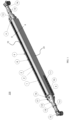
- the gas burner 20 includes a mounting component or system configured to allow mounting of the burner body on or in a heating system.
- the burner body 1 includes a mounting rail 10 with one or more mounting bolts 11, which can be utilized to mount the mounting rail 10 to the burner body.
- the ignitor or flame supervision device can be mounted to this rail via brackets.
- the bracket can be designed to slide on the rail, and the brackets can be installed or uninstalled by pushing clips.
- the mounting system can take many different forms and configurations.
- the burner body 1 of the gas burner system is an extruded body.
- the extruded body can be extruded aluminum, among many other possible metals or materials.
- the gas burner 20 can also include one or more components configured to enable operation of the burner. These components may be part of the heating system into which the burner is installed, or may be part of the gas burner itself such that the burner and accompanying components are installed together.
- the gas burner 20 includes at one or both ends of the burner body a reducing nipple 12, a pipe coupling 13, nipple 14, and gas supply connection 15.
- components 12, 13, 14, and/or 15 can form a connection to which the burner body is connected to a gas supply and components 16 and 17 can form a connection by which the burner body is connected to the cooling pipe.
- the burner body can comprise bolts for connection, or slots or holes that enable connection by bolts. Many other connection mechanisms are possible.
- the end of the burner body 1 comprises a plurality of holes or slots that enable a connection to the components and/or to the heating system.
- FIG. 2 is a partially exploded view of the gas burner system 100 of FIG. 1 .
- the gas burner system 100 comprises a burner body 20 and a ribbon pack 22 which is shown as it is being installed or uninstalled.
- the burner body 20 comprises a slot 24 into which the ribbon pack 22 will be positioned when it is installed.
- the slot 24 can be configured to receive a specific ribbon pack, or can be configured to receive a variety of different ribbon packs.
- the ribbon pack 22 comprises two transverse arms 2 which are formed at a right angle to the long axis of the ribbon pack 22.
- the two transverse arms 2 are located at the top of the ribbon pack, and enable the connection with the burner body 1 as described elsewhere herein in greater detail.
- the two transverse arms 2 each comprise a plurality of holes into which a fastening bolt 9 is positioned, which aligns with a thread hole 18.
- the fastening bolt is screwed or fastened into the thread hole 18 to hold the ribbon pack in place.
- each of the fastening bolts 9 are unscrewed or otherwise unfastened from the thread holes 18.
- the ribbon pack 22 also comprises one or more ribbons, with the count being dependent upon a variety of factors including but not limited to the heat input requirement of the heating system, among others.
- FIG. 2 also demonstrates that the burner body 1 can include one or more cooling passages to connect to a cooling water or air supply.
- the coolant fluid or gas enters the burner body 1 at one or more cooling openings 32, flows throughout the burner body, and can exit the burner body via the one or more cooling openings 32, or via different openings or exits.
- the cooling passages can be connected in any way or order to provide efficient cooling when the burner is firing and the cooled burner body keeps the controlled temperature which prevents the deformation of burner body.
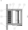
- ribbon pack 22 is a cross-section of ribbon pack 22 taken along axis A-A of FIG. 1 .
- ribbon pack 22 comprises a body formed by two vertical sides separated by top metal spacer 6 and bottom metal spacer 3.
- the metal spacers 3 and 6 determine the distance between the two vertical sides, and define the internal space for the one or more ribbons 8.
- the top metal spacer 6 is connected or adjoining the two transverse arms 2 which extend outwardly from the top of the ribbon pack.
- the ribbon pack also comprises a metal deckle 7, an adjusting bolt 4, and an adjustable thread binding 5.
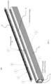
- FIG. 4 is a perspective view of the ribbon pack 22 of the gas burner system 100.
- the ribbon pack 22 comprises a top metal spacer 6, which may be formed, for example, over a portion of the ribbon pack 22.
- the ribbon pack 22 also comprises two transverse arms 2 which extend outwardly from the top of the ribbon pack, with a plurality of holes 26 through which the fastening bolts 9 are inserted to mate with the thread holes 18.
- Also shown in FIG. 4 is the end of the adjusting bolt 4 in the side wall of the ribbon pack 22.
- the insert in FIG. 4 is a top view of the ribbon pack, with two transverse arms 2 which extend outwardly from the top of the ribbon pack, the two arms comprise holes 26 through which the fastening bolts 9 are inserted to mate with the thread holes 18.
- the top view of the ribbon pack also shows the ribbons 8. In this particular embodiment there are eighteen ribbons, but there can be either more or fewer than eighteen ribbons.
- the ribbon pack comprises two side walls with a vertical portion 28 and a transverse arm 2 which extends outwardly away from the ribbons 8.
- the two transverse arms 2 each comprise a plurality of holes into which a fastening bolt 9 is positioned, which aligns with a thread hole 18.
- the fastening bolt is screwed or fastened into the thread hole 18 to hold the ribbon pack in place.
- the ribbon pack also comprises one or more top spacers 6 and a plurality of bottom spacers 3. Also shown is a metal deckle 7.
- the ribbon pack comprises a connection mechanism that connects the two sides of the ribbon pack together, thereby trapping the ribbons 8 in place without damaging or altering the structure of the ribbons.
- the connection mechanism comprises a plurality of adjusting bolts 4 connected to adjusting thread binding 5, although other connection mechanisms are possible.
- Ribbon pack 22 in FIG. 5 comprises one or more ribbons, with the count being dependent upon a variety of factors including but not limited to the heat input requirement of the heating system, among others.
- a gas burner 20 is provided, and at step 620 a replaceable ribbon pack 22 with one or more ribbons 8 is provided.
- the gas burner 20 and ribbon pack 22 can be any of the gas burners and ribbon packs described or otherwise envisioned herein.
- the burner body 1 can be extruded with aluminum or other material and the surface of burner body can be treated to prevent corrosion.
- the burner body 1 can include one or more cooling passages to connect to a cooling water or air supply.
- the burner body 1 can also provide a mechanical connection for the gas supply from either or both ends, which can be machined to connect the gas and air mixture supply.
- the gas and air mixture are introduced from either or both ends of the burner and the seamless connection between gas feeding and burner body 1 is designed to lessen or avoid the risk of gas leaking.
- a gas feeding pipe 12 and its pipe fitting parts are designed to provide smooth flow to the burner and uniform gas flow distribution along the length of the burner slot.
- transverse arms 2 can be welded by spacer metal 3 and 6, and the sheet flame ribbons 8 can be inserted between.
- the adjusting bolt 4 passes through beneath the ribbons and threads in the adjustable thread binding 5 to tighten the ribbon pack firmly to hold the ribbon.
- the ribbon pack is assembled on site or at a different site from the manufacture or location of the gas burner.
- the ribbons 8 are held by transverse arms 2 and clamped by adjusting bolts 5, which allows the ribbons to be easily replaced by loosening the adjusting bolts. All assembly parts of the ribbon pack are underneath the ribbons, and thus these components do not disturb flame characteristics.
- Metal deckle 7 can be installed above or below the ribbons to block the flame and thus the varying flame space can be achieved upon application requirement. According to an embodiment, therefore, a plurality of ribbons can be aligned next to each other and then bolted or otherwise connected to each other and then placed in the gas burner during manufacture.
- the ribbon pack 22 is installed into the gas burner 20.
- the ribbon pack is completely manufactured as a whole part and is mounted to the burner body via a mechanical linkage as described or envisioned herein.
- the burner body slot can be manufactured and/or machined to be larger than the ribbon pack, which allows the ribbon pack to easily fit into and be withdrawn from the ribbon pack slot.
- the ribbon pack can be easily installed to the burner body 1 by applying firmly mechanical linkage or uninstalled from the burner body 1 by removing the mechanical linkage.
- the two transverse arms 2 of the ribbon pack each comprise a plurality of holes into which a fastening bolt 9 is positioned, which aligns with a thread hole 18 on the burner body 1.
- Each of the plurality of fastening bolts is then screwed or fastened into a respective one of the plurality of thread holes 18 to hold the ribbon pack in place.
- the gas burner system 100 is assembled by installing the ribbon pack 22 into the gas burner 20, the system is ready to be utilized. Accordingly, at step 640 of the method, the gas burner system 100 is used. According to an embodiment, the gas burner system 100 described or otherwise envisioned herein has a wide variety of applications.
- the gas burner system with a replaceable ribbon pack can be utilized for lamination, searing decontamination, singeing, linear plastic 2D, metal foil, surface modification, converting, preheating, and a wide variety of other uses and application.
- the ribbon pack is removed when the ribbon pack requires replacement due to long-term use or due to different utilization requirements.
- the ribbons in the ribbon pack might be corroded, damaged, or otherwise need replacement.
- the gas burner might be used for a different purpose which requires a different ribbon pack of a different size, shape, number or shape of ribbons, among many other possible variations.
- Removing the ribbon pack can comprise, for example, removing each of the plurality of fastening bolts on the transverse arms from each of the respective thread holes 18 on the burner body. When all the fastening bolts are removed, the ribbon pack can easily be lifted out of the burner body.
- the cleaned or new ribbon pack is installed in the gas burner body.
- the two transverse arms 2 of the ribbon pack each comprise a plurality of holes into which a fastening bolt 9 is positioned, which aligns with a thread hole 18 on the burner body 1.
- Each of the plurality of fastening bolts is then screwed or fastened into a respective one of the plurality of thread holes 18 to hold the ribbon pack in place.
- the gas burner system 100 provides numerous advantages.
- the ribbon(s) and/or ribbon pack is easily removable within a couple of minutes without any special tools, devices, or systems. Additionally, because the ribbon(s) and/or ribbon pack are easily installed and removable, the burner can accommodate a variety of different ribbon pack sizes and configurations. Thus, a wide heat input is possible.
- the ribbon pack also has no impact on the free flow of the air and gas mixture, and does not disrupt the uniformity of the flame. Further, the ribbons can easily and quickly be cleaned, therefore saving both time and money.
Landscapes
- Engineering & Computer Science (AREA)
- Chemical & Material Sciences (AREA)
- Combustion & Propulsion (AREA)
- Mechanical Engineering (AREA)
- General Engineering & Computer Science (AREA)
- Gas Burners (AREA)
- Manufacture, Treatment Of Glass Fibers (AREA)
Claims (16)
- Ein austauschbares Bandpaket (22) für ein Gasbrennersystem (100), wobei das Bandpaket (22) Folgendes umfasst:mindestens ein Band (8), das zwischen einer ersten Längsseitenwand des Bandpakets (22) und einer zweiten Längsseitenwand des Bandpakets (22) angeordnet ist;einen ersten Querarm (2), der sich von der ersten Längsseitenwand des Bandpakets (22) senkrecht nach außen erstreckt;einen zweiten Querarm (2), der sich von der zweiten Längsseitenwand des Bandpakets (22) senkrecht nach außen erstreckt; undeinen Einstellbolzen (4) und eine Einstellgewindebindung (5), die so konfiguriert sind, dass sie die erste Längsseitenwand und die zweite Längsseitenwand einstellbar aneinander befestigen, wobei die erste Längsseitenwand eine Öffnung definiert, die so konfiguriert ist, dass sie den Einstellbolzen aufnimmt, wobei der erste und der zweite Querarm so konfiguriert sind, dass sie an einem Längsbrennerkörper (1) des Gasbrennersystems (100) angebracht werden.
- Das Bandpaket nach Anspruch 1, wobei das Bandpaket so konfiguriert ist, dass es herausnehmbar in einem zentralen Hohlraum des Längsbrennerkörpers (1) des Gasbrennersystems (100) installiert werden kann.
- Das Bandpaket nach Anspruch 1, wobei mindestens einer der ersten und zweiten Querarme (2) eine Vielzahl von Brennerkörper-Verbindungsöffnungen aufweist, die so konfiguriert sind, dass sie mit einer Vielzahl von Verbindungsöffnungen im Brennerkörper fluchten.
- Das Bandpaket nach Anspruch 1, wobei der erste und der zweite Querarm (2) so konfiguriert sind, dass sie an einer Außenfläche eines Längsbrennerkörpers (1) des Gasbrennersystems befestigt werden können.
- Ein Gasbrennersystem (100), wobei das System Folgendes umfasst:einen Längsbrennerkörper (1), wobei der Brennerkörper (1) einen länglichen zentralen Hohlraum definiert; undein Bandpaket (22) nach Anspruch 1, das so konfiguriert ist, dass es herausnehmbar in dem zentralen Hohlraum installiert werden kann.
- Das Gasbrennersystem (100) nach Anspruch 5, wobei der Längsbrennerkörper (1) eine Vielzahl von Bandpaket-Verbindungsöffnungen umfasst, die entlang mindestens einer Seite des länglichen zentralen Hohlraums angeordnet sind, und wobei mindestens einer der ersten und zweiten Querarme (2) eine Vielzahl von Brennerkörper-Verbindungsöffnungen umfasst, wobei die Vielzahl von Bandpaket-Verbindungsöffnungen und die Vielzahl von Brennerkörper-Verbindungsöffnungen so konfiguriert sind, dass sie ausgerichtet sind und ein Verbindungsmittel aufnehmen, um das Bandpaket (22) reversibel am Brennerkörper (1) zu befestigen.
- Das Gasbrennersystem (100) nach Anspruch 5, wobei der Brennerkörper außerdem einen Kühlkanal definiert.
- Das Gasbrennersystem (100) nach Anspruch 5, wobei der Brennerkörper einteilig ist und aus stranggepresstem Aluminium besteht.
- Das Gasbrennersystem (100) nach Anspruch 5 oder das Bandpaket nach Anspruch 1 umfasst außerdem eine Litze (7) .
- Das Gasbrennersystem (100) nach Anspruch 5 oder das Bandpaket (22) nach Anspruch 1, wobei das Bandpaket (22) ferner ein Gewinde umfasst, das in oder an der zweiten Längsseitenwand angeordnet ist, wobei das Gewinde so konfiguriert ist, dass es ein Ende des Einstellbolzens (4) aufnimmt.
- Ein Verfahren zum Installieren eines Bandpakets (22) in einem Gasbrenner (20), wobei das Verfahren die folgenden Schritte umfasst:Bereitstellen eines Bandpakets (22), das Folgendes umfasst: (i) mindestens ein Band (8), das zwischen einer ersten Längsseitenwand des Bandpakets (22) und einer zweiten Längsseitenwand des Bandpakets (22) angeordnet ist; (ii) einen ersten Querarm (2), der sich von der ersten Längsseitenwand des Bandpakets (22) senkrecht nach außen erstreckt; (iii) einen zweiten Querarm (2), der sich von der zweiten Längsseitenwand des Bandpakets (22) senkrecht nach außen erstreckt, und (iv) einen Einstellbolzen (4) und eine Einstellgewindebindung (5), die so konfiguriert sind, dass sie die erste Längsseitenwand und die zweite Längsseitenwand einstellbar aneinander befestigen, wobei die erste Längsseitenwand eine Öffnung definiert, die so konfiguriert ist, dass sie den Einstellbolzen (4) aufnimmt, wobei der erste und der zweite Querarm (2) so konfiguriert sind, dass sie an einem Längsbrennerkörper (1) des Gasbrennersystems (100) angebracht werden;Einsetzen des Bandpakets (22) in einen zentralen Längshohlraum eines Brennerkörpers; undBefestigen des Bandpakets (22) an dem Brennerkörper.
- Das Verfahren nach Anspruch 11, wobei mindestens einer der ersten und zweiten Querarme (2) eine Vielzahl von Brennerkörper-Verbindungsöffnungen aufweist, die so konfiguriert sind, dass sie mit einer Vielzahl von Verbindungsöffnungen im Brennerkörper fluchten.
- Das Verfahren nach Anspruch 11, wobei das Bandpaket (22) ferner ein Gewinde umfasst, das in oder an der zweiten Längsseitenwand angeordnet ist, wobei das Gewinde so konfiguriert ist, dass es ein Ende des Einstellbolzens (4) aufnimmt.
- Das Verfahren nach Anspruch 11, wobei der Brennerkörper außerdem einen Kühlkanal definiert.
- Das Verfahren nach Anspruch 11 umfasst ferner den Schritt des Entfernens des Bandpakets (22) aus dem Brennerkörper.
- Das Verfahren nach Anspruch 15 umfasst ferner den Schritt des Einbauens eines neuen Bandpakets (22) im Brennerkörper.
Applications Claiming Priority (2)
| Application Number | Priority Date | Filing Date | Title |
|---|---|---|---|
| US15/258,719 US10174941B2 (en) | 2016-09-07 | 2016-09-07 | Ribbon pack for gas burners |
| PCT/US2017/050027 WO2018048776A1 (en) | 2016-09-07 | 2017-09-05 | Ribbon pack for gas burners |
Publications (4)
| Publication Number | Publication Date |
|---|---|
| EP3510324A1 EP3510324A1 (de) | 2019-07-17 |
| EP3510324A4 EP3510324A4 (de) | 2020-03-25 |
| EP3510324B1 true EP3510324B1 (de) | 2024-06-12 |
| EP3510324C0 EP3510324C0 (de) | 2024-06-12 |
Family
ID=61281726
Family Applications (1)
| Application Number | Title | Priority Date | Filing Date |
|---|---|---|---|
| EP17849378.9A Active EP3510324B1 (de) | 2016-09-07 | 2017-09-05 | Streifenpackung für gasbrenner |
Country Status (11)
| Country | Link |
|---|---|
| US (1) | US10174941B2 (de) |
| EP (1) | EP3510324B1 (de) |
| JP (1) | JP6780096B2 (de) |
| KR (1) | KR102260582B1 (de) |
| CN (1) | CN109690191B (de) |
| BR (1) | BR112019004310A2 (de) |
| CA (1) | CA3035077C (de) |
| ES (1) | ES2984202T3 (de) |
| MX (1) | MX2019002237A (de) |
| PL (1) | PL3510324T3 (de) |
| WO (1) | WO2018048776A1 (de) |
Family Cites Families (32)
| Publication number | Priority date | Publication date | Assignee | Title |
|---|---|---|---|---|
| US1400024A (en) * | 1919-10-09 | 1921-12-13 | Gas Comb Company | Gas-burner |
| US1500513A (en) * | 1923-03-19 | 1924-07-08 | Edwin C Merrill | Gas burner |
| US1830464A (en) * | 1929-06-24 | 1931-11-03 | George A Guenther | Gas burner |
| US2228114A (en) | 1940-02-21 | 1941-01-07 | Selas Company | Gas burner |
| US2428271A (en) | 1943-10-28 | 1947-09-30 | Ensign Ribbon Burners Inc | Ribbon burner |
| US2588895A (en) * | 1946-02-04 | 1952-03-11 | Blackman Keith Ltd | Gas burner with flame retaining ports |
| US2607405A (en) | 1950-10-20 | 1952-08-19 | Surface Combustion Corp | Gas burner having removable port-forming grid |
| US2647569A (en) | 1951-05-24 | 1953-08-04 | John H Flynn | Ribbon-type gas burner-unit |
| US3047056A (en) * | 1959-11-12 | 1962-07-31 | John H Flynn | Ribbon assembly for gas burners |
| BE795392A (fr) * | 1973-01-10 | 1973-05-29 | Haller Meurer Werke Ag | Tube-bruleur en forme de caisson, servant de bruleur tout gaz aux appareils de chauffage au gaz |
| CA1138049A (en) * | 1979-01-16 | 1982-12-21 | William J. Day | Self-cleaning microwave convection oven |
| US4432727A (en) * | 1982-09-21 | 1984-02-21 | Joseph Fraioli | Gas-fired infrared projection heater |
| JPS59143109A (ja) * | 1983-02-04 | 1984-08-16 | Sumitomo Electric Ind Ltd | 光集積回路 |
| US4904179A (en) * | 1985-08-20 | 1990-02-27 | Carrier Corporation | Low NOx primary zone radiant screen device |
| US5346389A (en) * | 1989-02-24 | 1994-09-13 | W. R. Grace & Co.-Conn. | Combustion apparatus for high-temperature environment |
| GB2237104B (en) * | 1989-10-20 | 1993-07-21 | Bowin Designs Pty Ltd | Gas burner |
| SG49198A1 (en) * | 1992-06-30 | 1998-05-18 | Chem Mech Engineering | Flame arrestor apparatus |
| AU666034B2 (en) * | 1992-09-11 | 1996-01-25 | Rinnai Kabushiki Kaisha | A porous gas burner for a water heater and a method of making thereof |
| US5636981A (en) * | 1994-05-19 | 1997-06-10 | Lilly Engineering Company | Fuel oil burner |
| US5546925A (en) * | 1995-08-09 | 1996-08-20 | Rheem Manufacturing Company | Inshot fuel burner Nox reduction device with integral positioning support structure |
| JP3631567B2 (ja) * | 1996-10-02 | 2005-03-23 | 大阪瓦斯株式会社 | ラインバーナ |
| US6200131B1 (en) * | 2000-02-29 | 2001-03-13 | Recot, Inc. | Quick-connect burner set for ovens |
| US6918759B2 (en) * | 2002-10-22 | 2005-07-19 | Kyungdong Boiler Co., Ltd. | Premixed combustion gas burner having separated fire hole units |
| JP3702276B2 (ja) * | 2003-03-24 | 2005-10-05 | 内外施設工業株式会社 | 二次空気内蔵型ガス焼成装置用バーナ |
| DE102006026510B3 (de) * | 2006-06-06 | 2007-05-24 | Leinemann Gmbh & Co. Kg | Flammensperreinsatz und Verfahren zu seiner Herstellung |
| DE102006026779A1 (de) * | 2006-06-07 | 2007-12-20 | Leinemann Gmbh & Co. Kg | Flammensperranordnung und Verfahren zum Einbringen von Bohrungen in eine Flammensperranordnung |
| JP4501141B2 (ja) * | 2006-11-14 | 2010-07-14 | 日新工業株式会社 | ガス焼成装置 |
| US8105077B2 (en) * | 2007-08-17 | 2012-01-31 | Red-Ray Manufacturing, Co., Inc. | Integrated operating and control package for a pressurized burner system |
| US7635264B2 (en) | 2007-12-20 | 2009-12-22 | 3M Innovative Properties Company | Attenuating combustion noise of premixed flames |
| US9551488B2 (en) * | 2014-06-20 | 2017-01-24 | Rinnai Corporation | Flat burner |
| US9731155B2 (en) * | 2014-09-05 | 2017-08-15 | Empyreus Solutions Llc | Flame arrester with porous sleeve |
| US20170248306A1 (en) * | 2016-02-25 | 2017-08-31 | Flynn Burner Corporation | Combination burner |
-
2016
- 2016-09-07 US US15/258,719 patent/US10174941B2/en active Active
-
2017
- 2017-09-05 MX MX2019002237A patent/MX2019002237A/es unknown
- 2017-09-05 CA CA3035077A patent/CA3035077C/en active Active
- 2017-09-05 WO PCT/US2017/050027 patent/WO2018048776A1/en not_active Ceased
- 2017-09-05 CN CN201780054673.7A patent/CN109690191B/zh active Active
- 2017-09-05 PL PL17849378.9T patent/PL3510324T3/pl unknown
- 2017-09-05 KR KR1020197006421A patent/KR102260582B1/ko active Active
- 2017-09-05 ES ES17849378T patent/ES2984202T3/es active Active
- 2017-09-05 JP JP2019511575A patent/JP6780096B2/ja active Active
- 2017-09-05 EP EP17849378.9A patent/EP3510324B1/de active Active
- 2017-09-05 BR BR112019004310A patent/BR112019004310A2/pt not_active Application Discontinuation
Also Published As
| Publication number | Publication date |
|---|---|
| EP3510324A1 (de) | 2019-07-17 |
| WO2018048776A1 (en) | 2018-03-15 |
| CA3035077C (en) | 2021-07-13 |
| US20180066843A1 (en) | 2018-03-08 |
| KR20190034328A (ko) | 2019-04-01 |
| US10174941B2 (en) | 2019-01-08 |
| CA3035077A1 (en) | 2018-03-15 |
| JP2019529851A (ja) | 2019-10-17 |
| JP6780096B2 (ja) | 2020-11-04 |
| BR112019004310A2 (pt) | 2019-05-28 |
| EP3510324C0 (de) | 2024-06-12 |
| PL3510324T3 (pl) | 2024-10-21 |
| MX2019002237A (es) | 2019-09-19 |
| CN109690191B (zh) | 2020-11-06 |
| KR102260582B1 (ko) | 2021-06-04 |
| CN109690191A (zh) | 2019-04-26 |
| ES2984202T3 (es) | 2024-10-29 |
| EP3510324A4 (de) | 2020-03-25 |
Similar Documents
| Publication | Publication Date | Title |
|---|---|---|
| JP2006349075A (ja) | 流体制御装置 | |
| JP6769715B2 (ja) | 散水装置 | |
| ITTO970785A1 (it) | Dispositivo pe regolare l'alimentazione di un gas e per regolare una pressione di lavoro ad un dispositivo di cottura a gas con bru- | |
| KR101364978B1 (ko) | 분리형 증착물질 공급장치 | |
| CA3035077C (en) | Ribbon pack for gas burners | |
| KR20150122212A (ko) | 저온 액화 가스의 기화 장치 | |
| US8826969B2 (en) | Inlet arrangement | |
| EP2341287B1 (de) | Wartungsmethode für eine Brennkammer eines Gasturbinenkraftwerk | |
| EA032715B1 (ru) | Конструкция распределителя сырья для реактора аммоксидирования | |
| JP4585414B2 (ja) | 振動防止装置およびこれを用いた熱交換器 | |
| KR102448184B1 (ko) | 분리 가능한 제빙판을 포함하는 제빙기 | |
| CA2711901A1 (en) | Drop-out steam profiling cartridge | |
| CA2843663C (en) | Continuous flow multi stage gas contact water heater | |
| CN213482104U (zh) | 一种混凝土冻融机 | |
| KR101380369B1 (ko) | 열교환관 착탈식 보일러 | |
| US20220034603A1 (en) | A heat exchanger | |
| JP2017007276A (ja) | ライナ式バレル | |
| CN217356837U (zh) | 多级串联蒸汽发生器 | |
| EP3143356B1 (de) | Verteiler für kältemittelfluid in einem wärmetauscher | |
| ITMI20122104A1 (it) | Struttura di supporto per piastrelle termoisolanti di camere di combustione di turbine a gas, modulo termoisolante e camera di combustione di turbina a gas | |
| KR101166769B1 (ko) | 온수 보일러 | |
| US20150323222A1 (en) | Heat Exchanger Device and System Technologies | |
| RU2269071C1 (ru) | Нагреватель | |
| KR101281800B1 (ko) | 얼음 공급모듈 및 이를 갖는 얼음 공급장치 | |
| JP6548968B2 (ja) | 凍結工法及びそれに使用する装置 |
Legal Events
| Date | Code | Title | Description |
|---|---|---|---|
| STAA | Information on the status of an ep patent application or granted ep patent |
Free format text: STATUS: THE INTERNATIONAL PUBLICATION HAS BEEN MADE |
|
| PUAI | Public reference made under article 153(3) epc to a published international application that has entered the european phase |
Free format text: ORIGINAL CODE: 0009012 |
|
| STAA | Information on the status of an ep patent application or granted ep patent |
Free format text: STATUS: REQUEST FOR EXAMINATION WAS MADE |
|
| 17P | Request for examination filed |
Effective date: 20190306 |
|
| AK | Designated contracting states |
Kind code of ref document: A1 Designated state(s): AL AT BE BG CH CY CZ DE DK EE ES FI FR GB GR HR HU IE IS IT LI LT LU LV MC MK MT NL NO PL PT RO RS SE SI SK SM TR |
|
| AX | Request for extension of the european patent |
Extension state: BA ME |
|
| DAV | Request for validation of the european patent (deleted) | ||
| DAX | Request for extension of the european patent (deleted) | ||
| A4 | Supplementary search report drawn up and despatched |
Effective date: 20200224 |
|
| RIC1 | Information provided on ipc code assigned before grant |
Ipc: F23D 14/58 20060101AFI20200218BHEP Ipc: F23D 14/48 20060101ALI20200218BHEP Ipc: F23D 99/00 20100101ALI20200218BHEP |
|
| STAA | Information on the status of an ep patent application or granted ep patent |
Free format text: STATUS: EXAMINATION IS IN PROGRESS |
|
| 17Q | First examination report despatched |
Effective date: 20201207 |
|
| P01 | Opt-out of the competence of the unified patent court (upc) registered |
Effective date: 20230530 |
|
| GRAP | Despatch of communication of intention to grant a patent |
Free format text: ORIGINAL CODE: EPIDOSNIGR1 |
|
| STAA | Information on the status of an ep patent application or granted ep patent |
Free format text: STATUS: GRANT OF PATENT IS INTENDED |
|
| INTG | Intention to grant announced |
Effective date: 20231026 |
|
| GRAJ | Information related to disapproval of communication of intention to grant by the applicant or resumption of examination proceedings by the epo deleted |
Free format text: ORIGINAL CODE: EPIDOSDIGR1 |
|
| STAA | Information on the status of an ep patent application or granted ep patent |
Free format text: STATUS: EXAMINATION IS IN PROGRESS |
|
| GRAP | Despatch of communication of intention to grant a patent |
Free format text: ORIGINAL CODE: EPIDOSNIGR1 |
|
| STAA | Information on the status of an ep patent application or granted ep patent |
Free format text: STATUS: GRANT OF PATENT IS INTENDED |
|
| INTC | Intention to grant announced (deleted) | ||
| INTG | Intention to grant announced |
Effective date: 20240109 |
|
| GRAS | Grant fee paid |
Free format text: ORIGINAL CODE: EPIDOSNIGR3 |
|
| GRAA | (expected) grant |
Free format text: ORIGINAL CODE: 0009210 |
|
| STAA | Information on the status of an ep patent application or granted ep patent |
Free format text: STATUS: THE PATENT HAS BEEN GRANTED |
|
| AK | Designated contracting states |
Kind code of ref document: B1 Designated state(s): AL AT BE BG CH CY CZ DE DK EE ES FI FR GB GR HR HU IE IS IT LI LT LU LV MC MK MT NL NO PL PT RO RS SE SI SK SM TR |
|
| REG | Reference to a national code |
Ref country code: GB Ref legal event code: FG4D |
|
| REG | Reference to a national code |
Ref country code: CH Ref legal event code: EP |
|
| REG | Reference to a national code |
Ref country code: DE Ref legal event code: R096 Ref document number: 602017082582 Country of ref document: DE |
|
| REG | Reference to a national code |
Ref country code: IE Ref legal event code: FG4D |
|
| U01 | Request for unitary effect filed |
Effective date: 20240705 |
|
| U07 | Unitary effect registered |
Designated state(s): AT BE BG DE DK EE FI FR IT LT LU LV MT NL PT SE SI Effective date: 20240716 |
|
| P04 | Withdrawal of opt-out of the competence of the unified patent court (upc) registered |
Free format text: CASE NUMBER: APP_41240/2024 Effective date: 20240712 |
|
| U20 | Renewal fee for the european patent with unitary effect paid |
Year of fee payment: 8 Effective date: 20240807 |
|
| PG25 | Lapsed in a contracting state [announced via postgrant information from national office to epo] |
Ref country code: HR Free format text: LAPSE BECAUSE OF FAILURE TO SUBMIT A TRANSLATION OF THE DESCRIPTION OR TO PAY THE FEE WITHIN THE PRESCRIBED TIME-LIMIT Effective date: 20240612 |
|
| PG25 | Lapsed in a contracting state [announced via postgrant information from national office to epo] |
Ref country code: GR Free format text: LAPSE BECAUSE OF FAILURE TO SUBMIT A TRANSLATION OF THE DESCRIPTION OR TO PAY THE FEE WITHIN THE PRESCRIBED TIME-LIMIT Effective date: 20240913 |
|
| REG | Reference to a national code |
Ref country code: ES Ref legal event code: FG2A Ref document number: 2984202 Country of ref document: ES Kind code of ref document: T3 Effective date: 20241029 |
|
| PG25 | Lapsed in a contracting state [announced via postgrant information from national office to epo] |
Ref country code: NO Free format text: LAPSE BECAUSE OF FAILURE TO SUBMIT A TRANSLATION OF THE DESCRIPTION OR TO PAY THE FEE WITHIN THE PRESCRIBED TIME-LIMIT Effective date: 20240912 Ref country code: HR Free format text: LAPSE BECAUSE OF FAILURE TO SUBMIT A TRANSLATION OF THE DESCRIPTION OR TO PAY THE FEE WITHIN THE PRESCRIBED TIME-LIMIT Effective date: 20240612 Ref country code: GR Free format text: LAPSE BECAUSE OF FAILURE TO SUBMIT A TRANSLATION OF THE DESCRIPTION OR TO PAY THE FEE WITHIN THE PRESCRIBED TIME-LIMIT Effective date: 20240913 Ref country code: RS Free format text: LAPSE BECAUSE OF FAILURE TO SUBMIT A TRANSLATION OF THE DESCRIPTION OR TO PAY THE FEE WITHIN THE PRESCRIBED TIME-LIMIT Effective date: 20240912 |
|
| REG | Reference to a national code |
Ref country code: SK Ref legal event code: T3 Ref document number: E 44878 Country of ref document: SK |
|
| P05 | Withdrawal of opt-out of the competence of the unified patent court (upc) changed |
Free format text: CASE NUMBER: APP_41240/2024 Effective date: 20240716 |
|
| PG25 | Lapsed in a contracting state [announced via postgrant information from national office to epo] |
Ref country code: IS Free format text: LAPSE BECAUSE OF FAILURE TO SUBMIT A TRANSLATION OF THE DESCRIPTION OR TO PAY THE FEE WITHIN THE PRESCRIBED TIME-LIMIT Effective date: 20241012 |
|
| PG25 | Lapsed in a contracting state [announced via postgrant information from national office to epo] |
Ref country code: RO Free format text: LAPSE BECAUSE OF FAILURE TO SUBMIT A TRANSLATION OF THE DESCRIPTION OR TO PAY THE FEE WITHIN THE PRESCRIBED TIME-LIMIT Effective date: 20240612 |
|
| PG25 | Lapsed in a contracting state [announced via postgrant information from national office to epo] |
Ref country code: SM Free format text: LAPSE BECAUSE OF FAILURE TO SUBMIT A TRANSLATION OF THE DESCRIPTION OR TO PAY THE FEE WITHIN THE PRESCRIBED TIME-LIMIT Effective date: 20240612 |
|
| PG25 | Lapsed in a contracting state [announced via postgrant information from national office to epo] |
Ref country code: SM Free format text: LAPSE BECAUSE OF FAILURE TO SUBMIT A TRANSLATION OF THE DESCRIPTION OR TO PAY THE FEE WITHIN THE PRESCRIBED TIME-LIMIT Effective date: 20240612 Ref country code: RO Free format text: LAPSE BECAUSE OF FAILURE TO SUBMIT A TRANSLATION OF THE DESCRIPTION OR TO PAY THE FEE WITHIN THE PRESCRIBED TIME-LIMIT Effective date: 20240612 Ref country code: IS Free format text: LAPSE BECAUSE OF FAILURE TO SUBMIT A TRANSLATION OF THE DESCRIPTION OR TO PAY THE FEE WITHIN THE PRESCRIBED TIME-LIMIT Effective date: 20241012 |
|
| PLBE | No opposition filed within time limit |
Free format text: ORIGINAL CODE: 0009261 |
|
| STAA | Information on the status of an ep patent application or granted ep patent |
Free format text: STATUS: NO OPPOSITION FILED WITHIN TIME LIMIT |
|
| PG25 | Lapsed in a contracting state [announced via postgrant information from national office to epo] |
Ref country code: MC Free format text: LAPSE BECAUSE OF FAILURE TO SUBMIT A TRANSLATION OF THE DESCRIPTION OR TO PAY THE FEE WITHIN THE PRESCRIBED TIME-LIMIT Effective date: 20240612 |
|
| 26N | No opposition filed |
Effective date: 20250313 |
|
| PG25 | Lapsed in a contracting state [announced via postgrant information from national office to epo] |
Ref country code: IE Free format text: LAPSE BECAUSE OF NON-PAYMENT OF DUE FEES Effective date: 20240905 |
|
| REG | Reference to a national code |
Ref country code: CH Ref legal event code: U11 Free format text: ST27 STATUS EVENT CODE: U-0-0-U10-U11 (AS PROVIDED BY THE NATIONAL OFFICE) Effective date: 20251001 |
|
| PGFP | Annual fee paid to national office [announced via postgrant information from national office to epo] |
Ref country code: PL Payment date: 20250827 Year of fee payment: 9 |
|
| U20 | Renewal fee for the european patent with unitary effect paid |
Year of fee payment: 9 Effective date: 20250909 |
|
| PGFP | Annual fee paid to national office [announced via postgrant information from national office to epo] |
Ref country code: GB Payment date: 20250821 Year of fee payment: 9 |
|
| PGFP | Annual fee paid to national office [announced via postgrant information from national office to epo] |
Ref country code: CZ Payment date: 20250901 Year of fee payment: 9 |
|
| PGFP | Annual fee paid to national office [announced via postgrant information from national office to epo] |
Ref country code: SK Payment date: 20250827 Year of fee payment: 9 |
|
| PGFP | Annual fee paid to national office [announced via postgrant information from national office to epo] |
Ref country code: CH Payment date: 20251001 Year of fee payment: 9 |
|
| PG25 | Lapsed in a contracting state [announced via postgrant information from national office to epo] |
Ref country code: CY Free format text: LAPSE BECAUSE OF FAILURE TO SUBMIT A TRANSLATION OF THE DESCRIPTION OR TO PAY THE FEE WITHIN THE PRESCRIBED TIME-LIMIT; INVALID AB INITIO Effective date: 20170905 |
|
| PGFP | Annual fee paid to national office [announced via postgrant information from national office to epo] |
Ref country code: ES Payment date: 20251016 Year of fee payment: 9 |
|
| PG25 | Lapsed in a contracting state [announced via postgrant information from national office to epo] |
Ref country code: HU Free format text: LAPSE BECAUSE OF FAILURE TO SUBMIT A TRANSLATION OF THE DESCRIPTION OR TO PAY THE FEE WITHIN THE PRESCRIBED TIME-LIMIT; INVALID AB INITIO Effective date: 20170905 |