EP3510253B1 - Vorrichtung zur steuerung von lufteinlassklappen mit einem mehrschichtigen piezoelektrischen aktuator - Google Patents
Vorrichtung zur steuerung von lufteinlassklappen mit einem mehrschichtigen piezoelektrischen aktuator Download PDFInfo
- Publication number
- EP3510253B1 EP3510253B1 EP17768490.9A EP17768490A EP3510253B1 EP 3510253 B1 EP3510253 B1 EP 3510253B1 EP 17768490 A EP17768490 A EP 17768490A EP 3510253 B1 EP3510253 B1 EP 3510253B1
- Authority
- EP
- European Patent Office
- Prior art keywords
- electric actuator
- electromagnets
- actuator according
- movable
- parallel
- Prior art date
- Legal status (The legal status is an assumption and is not a legal conclusion. Google has not performed a legal analysis and makes no representation as to the accuracy of the status listed.)
- Active
Links
Images

Classifications
-
- F—MECHANICAL ENGINEERING; LIGHTING; HEATING; WEAPONS; BLASTING
- F01—MACHINES OR ENGINES IN GENERAL; ENGINE PLANTS IN GENERAL; STEAM ENGINES
- F01D—NON-POSITIVE DISPLACEMENT MACHINES OR ENGINES, e.g. STEAM TURBINES
- F01D17/00—Regulating or controlling by varying flow
- F01D17/20—Devices dealing with sensing elements or final actuators or transmitting means between them, e.g. power-assisted
- F01D17/22—Devices dealing with sensing elements or final actuators or transmitting means between them, e.g. power-assisted the operation or power assistance being predominantly non-mechanical
- F01D17/24—Devices dealing with sensing elements or final actuators or transmitting means between them, e.g. power-assisted the operation or power assistance being predominantly non-mechanical electrical
-
- F—MECHANICAL ENGINEERING; LIGHTING; HEATING; WEAPONS; BLASTING
- F01—MACHINES OR ENGINES IN GENERAL; ENGINE PLANTS IN GENERAL; STEAM ENGINES
- F01D—NON-POSITIVE DISPLACEMENT MACHINES OR ENGINES, e.g. STEAM TURBINES
- F01D17/00—Regulating or controlling by varying flow
- F01D17/10—Final actuators
- F01D17/12—Final actuators arranged in stator parts
- F01D17/14—Final actuators arranged in stator parts varying effective cross-sectional area of nozzles or guide conduits
- F01D17/16—Final actuators arranged in stator parts varying effective cross-sectional area of nozzles or guide conduits by means of nozzle vanes
- F01D17/162—Final actuators arranged in stator parts varying effective cross-sectional area of nozzles or guide conduits by means of nozzle vanes for axial flow, i.e. the vanes turning around axes which are essentially perpendicular to the rotor centre line
-
- F—MECHANICAL ENGINEERING; LIGHTING; HEATING; WEAPONS; BLASTING
- F01—MACHINES OR ENGINES IN GENERAL; ENGINE PLANTS IN GENERAL; STEAM ENGINES
- F01D—NON-POSITIVE DISPLACEMENT MACHINES OR ENGINES, e.g. STEAM TURBINES
- F01D9/00—Stators
- F01D9/02—Nozzles; Nozzle boxes; Stator blades; Guide conduits, e.g. individual nozzles
- F01D9/04—Nozzles; Nozzle boxes; Stator blades; Guide conduits, e.g. individual nozzles forming ring or sector
- F01D9/041—Nozzles; Nozzle boxes; Stator blades; Guide conduits, e.g. individual nozzles forming ring or sector using blades
-
- F—MECHANICAL ENGINEERING; LIGHTING; HEATING; WEAPONS; BLASTING
- F02—COMBUSTION ENGINES; HOT-GAS OR COMBUSTION-PRODUCT ENGINE PLANTS
- F02C—GAS-TURBINE PLANTS; AIR INTAKES FOR JET-PROPULSION PLANTS; CONTROLLING FUEL SUPPLY IN AIR-BREATHING JET-PROPULSION PLANTS
- F02C9/00—Controlling gas-turbine plants; Controlling fuel supply in air- breathing jet-propulsion plants
- F02C9/16—Control of working fluid flow
- F02C9/20—Control of working fluid flow by throttling; by adjusting vanes
-
- F—MECHANICAL ENGINEERING; LIGHTING; HEATING; WEAPONS; BLASTING
- F05—INDEXING SCHEMES RELATING TO ENGINES OR PUMPS IN VARIOUS SUBCLASSES OF CLASSES F01-F04
- F05D—INDEXING SCHEME FOR ASPECTS RELATING TO NON-POSITIVE-DISPLACEMENT MACHINES OR ENGINES, GAS-TURBINES OR JET-PROPULSION PLANTS
- F05D2240/00—Components
- F05D2240/50—Bearings
- F05D2240/51—Magnetic
- F05D2240/515—Electromagnetic
-
- Y—GENERAL TAGGING OF NEW TECHNOLOGICAL DEVELOPMENTS; GENERAL TAGGING OF CROSS-SECTIONAL TECHNOLOGIES SPANNING OVER SEVERAL SECTIONS OF THE IPC; TECHNICAL SUBJECTS COVERED BY FORMER USPC CROSS-REFERENCE ART COLLECTIONS [XRACs] AND DIGESTS
- Y02—TECHNOLOGIES OR APPLICATIONS FOR MITIGATION OR ADAPTATION AGAINST CLIMATE CHANGE
- Y02T—CLIMATE CHANGE MITIGATION TECHNOLOGIES RELATED TO TRANSPORTATION
- Y02T50/00—Aeronautics or air transport
- Y02T50/60—Efficient propulsion technologies, e.g. for aircraft
Definitions
- the present invention relates to the general field of compressors and turbines for aeronautical engines (in particular for aircraft or helicopters). It relates more specifically to the control of the air inlet flaps (IGV for Inlet Guides Vanes) of a gas turbine engine.
- IGV Inlet Guides Vanes
- IGV actuators are used to control the position of the pre-rotation blades located upstream of the compressor stage (s) on turbine engines for helicopters (see for example US 2014/0286745 ).
- the function of this actuator is to direct the flow of air entering the motor upstream of the compressor.
- the variation of the angular position of the pre-rotation blades makes it possible to optimize the overall performance of the engine (transients and specific consumption).
- the object of the present invention is therefore to alleviate the aforementioned drawbacks by proposing a high-performance actuator optimized for the sole control function of IGVs and also exhibiting particularly secure behavior.
- an electric actuator for gas turbine engine air inlet flaps comprising a fixed part integral with a stationary part of said engine and a movable part in mechanical connection with said inlet flaps.
- said electric actuator comprises, regularly distributed around the periphery of said movable part and fixed to said fixed part, fixed electromagnets and arranged between said fixed electromagnets, movable electromagnets each secured on either side to first and second piezoelectric elements, said movable electromagnets and said first and second piezoelectric elements having a degree of freedom of movement relative to said movable part.
- the fixed part is a rotary actuator stator
- the movable part a rotary actuator rotor and said degree of freedom of movement is a degree of freedom in rotation about an axis of rotation of said rotor.
- each piezoelectric element is formed from a series of N ceramics arranged in one or more layers.
- said piezoelectric element comprises two superimposed layers of ten ceramics placed in parallel.
- said fixed electromagnets constitute an integral part of said stator, of which they then form an internal serration.
- said fixed electromagnets are electrically connected in parallel to a first direct voltage source DC1 and said mobile electromagnets are electrically connected in parallel to a second direct voltage source DC2.
- said direct voltage sources deliver two opposite signals.
- said first piezoelectric element is electrically connected in parallel to a first source of alternating voltage AC1 and said second piezoelectric element is electrically connected in parallel to a second source of alternating voltage AC2.
- the invention also relates to a gas turbine engine comprising at least one above-mentioned electric actuator.
- FIG 1 schematically illustrates a gas turbine engine 10 conventionally comprising a compressor 12, a combustion chamber 14 and a turbine 16 intended for driving the blades of the engine (not shown).
- a gas turbine engine 10 conventionally comprising a compressor 12, a combustion chamber 14 and a turbine 16 intended for driving the blades of the engine (not shown).
- IGV 18 air inlet flaps
- ACT 20 actuators
- FADEC 22 central computer
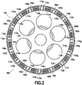
- the actuator of the air intake flaps is an electric actuator which takes the form of the particular rotary piezoelectric motor illustrated in figure 2 .
- the piezoelectric motor 100 comprises a central rotor 102 surrounded by an annular stator 104.
- the central rotor advantageously perforated to save weight, is in fixed connection with the lever which actuates the air inlet flaps, the lever being pivotally connected to the motor casing while the stator is in fixed connection with a stationary part of the motor.
- magnetic bodies form with associated windings 106a - 106h fixed electromagnets 108a - 108h positioned at regular intervals.
- Magnetic bodies can also constitute an integral part of the stator, of which they then form like an internal serration.
- movable electromagnets 110a - 110h each formed of magnetic bodies and associated coils 112a - 112h
- a piezoelectric element 114a - 114h; 116a - 116h Each piezoelectric element is formed from a series of ceramics arranged in one or more layers. In the example illustrated, which cannot be considered as limiting, the piezoelectric element comprises two superimposed layers of ten ceramics placed in parallel. The height of the ceramic layer (s) corresponds to that of the fixed or mobile magnetic bodies which surround them, so that the internal face of these various constituents forms a same tangent contact line with the central rotor 102.
- the movable electromagnets 110a - 110h and the first and second piezoelectric elements 114a - 114h; 116a - 116h have a degree of freedom of movement in rotation around the axis of the central rotor 102, without any friction between stator and rotor (due to the presence of an unreferenced air gap), unlike a configuration of piezoelectric motor of known type.
- This gap associated with the way of using the piezoelectric elements makes it possible to counter one of the main problems linked to this piezoelectric technology: the wear of the polymers to which the piezoelectric components adhere. By limiting / eliminating friction, the service life and availability of the equipment are increased, making it compatible with aeronautical use.
- the fixed electromagnets 108a, 108b, 108c are electrically connected in parallel to a first DC voltage source DC1 (curve 120 of the figure 3 ) and the mobile electromagnets 110a, 110b are electrically connected in parallel to a second direct voltage source DC2 (curve 122 of the figure 3 ), the sources DC1 and DC2 delivering opposite signals.
- the first piezoelectric element 114a, 114b is electrically connected in parallel to a first alternating voltage source AC1 (curve 124 of the figure 3 ) and the second piezoelectric element 116a, 116b is electrically connected in parallel to a second alternating voltage source AC2 (curve 126 of the figure 3 ).
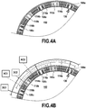
- the piezoelectric elements and the electromagnets must be supplied in two stages, defining four successive phases as follows:
- the figure 4A shows the initial phase in which the fixed electromagnets 108a, 108b, 108c are traversed by a current (the voltage source DC1 is positive) and therefore maintain contact with the central rotor 102.
- the mobile electromagnets 110a, 110b are deactivated (the source of direct voltage DC2 is at zero) and the first and second piezoelectric elements 114a, 114b; 116a, 116b are in the initial rest position.
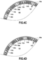
- the elongation / retraction movement of the piezoelectric elements is completed and the mobile electromagnets 110a, 110b are then energized (the voltage source DC2 is made positive) to maintain contact with the central rotor 102. Simultaneously, the fixed electromagnets 108a, 108b, 108c are deactivated (the DC voltage source DC1 is set to zero).
- the figure 4D shows the last phase when the first piezoelectric elements 114a, 114b retract and the second piezoelectric elements 116a, 116b lengthen to resume their initial shape, dragging with them the movable electromagnets 110a, 110b (in the direction illustrated by arrow) and therefore also the central rotor 102 on which they are kept in contact.
- the effective rotation of the motor corresponds to a cycle of extension / retraction of the piezoelectric elements.
- such a linear piezoelectric motor 200 comprises a movable part 202 and a fixed part 204.
- the movable part is in fixed connection with the lever which actuates the air inlet flaps and the mobile part is in a fixed connection with a stationary part of the engine.
- magnetic bodies Regularly distributed around the periphery of this mobile part and fixed to the fixed part, magnetic bodies form, with associated coils 206a - 206b, fixed electromagnets 208a - 208b positioned at regular intervals. Magnetic bodies can also constitute an integral part of this fixed part.
- movable electromagnets 210a - 210b (each formed of magnetic bodies and associated coils 212a - 212b) each secured on either side to a piezoelectric element 214a - 114b; 216a - 216b each formed of a series of ceramics arranged in one or more layers, the internal face of these different constituents forming the same tangent contact line (at an air gap 218 near excessively magnified for the purposes of explanation) with the movable part 202.
- the movable electromagnets 210a - 210b and the first and second piezoelectric elements 214a - 214b; 216a - 216b have a degree of freedom of translational movement along the movable part 202, without any friction between stator and rotor.
- the gain in mass is very significant, the mass of the actuator (of the order of 500 g) being able to be reduced. by a factor of 5 compared to a hydraulic IGV actuator conventionally weighing around 2500g.
- the dynamic performances of a piezoelectric actuator are also much better: up to 200mm / s at full load (100daN) against 8.5mm / s for a hydraulic actuator type RTM322 and a gain in precision of a few micrometers ( against +/- 0.2mm on an RTM322).
Landscapes
- Engineering & Computer Science (AREA)
- Mechanical Engineering (AREA)
- General Engineering & Computer Science (AREA)
- Chemical & Material Sciences (AREA)
- Combustion & Propulsion (AREA)
- Physics & Mathematics (AREA)
- Fluid Mechanics (AREA)
- General Electrical Machinery Utilizing Piezoelectricity, Electrostriction Or Magnetostriction (AREA)
- Structures Of Non-Positive Displacement Pumps (AREA)
- Connection Of Motors, Electrical Generators, Mechanical Devices, And The Like (AREA)
Claims (10)
- Elektrischer Aktor für Lufteinlassklappen eines Gasturbinentriebwerks, umfassend einen festen Teil (104, 204), der mit einem stationären Teil des Triebwerks fest verbunden ist, und einen beweglichen Teil (102, 202), der mit den Lufteinlassklappen in mechanischer Verbindung steht, dadurch gekennzeichnet, dass der elektrische Aktor (100, 200) feste Elektromagnete (108a - 108h; 208a - 208c), die am Umfang des beweglichen Teils gleichmäßig verteilt und an dem festen Teil befestigt sind, sowie bewegliche Elektromagnete (110a - 110h; 210a - 210c) umfasst, die zwischen den festen Elektromagneten angeordnet und jeweils auf beiden Seiten mit ersten (114a - 114h; 214a - 214c) und zweiten (116a, 116h; 216a, 216c) piezoelektrischen Elementen fest verbunden sind, wobei die beweglichen Elektromagnete sowie die ersten und zweiten piezoelektrischen Elemente über einen Bewegungsfreiheitsgrad gegenüber dem beweglichen Teil verfügen.
- Elektrischer Aktor nach Anspruch 1, bei dem der feste Teil ein Rotationsaktorstator (104) ist, der bewegliche Teil ein Rotationsaktorrotor (102) ist und der Bewegungsfreiheitsgrad ein Drehfreiheitsgrad um eine Rotationsachse des Rotors ist.
- Elektrischer Aktor nach Anspruch 1 oder Anspruch 2, bei dem jedes piezoelektrische Element aus einer Reihe von N Keramiken gebildet ist, die in einer oder mehreren Schichten angeordnet ist.
- Elektrischer Aktor nach Anspruch 3, bei dem das piezoelektrische Element zwei übereinander liegende Schichten aus zehn parallel angeordneten Keramiken umfasst.
- Elektrischer Aktor nach Anspruch 3 oder Anspruch 4, bei dem die festen Elektromagnete einen integralen Bestandteil des Stators bilden, von dem sie dann eine Innenverzahnung bilden.
- Elektrischer Aktor nach einem der Ansprüche 1 bis 5, bei dem die festen Elektromagnete zu einer ersten Gleichspannungsquelle DC1 elektrisch parallel geschaltet sind und die beweglichen Elektromagnete zu einer zweiten Gleichspannungsquelle DC2 elektrisch parallel geschaltet sind.
- Elektrischer Aktor nach Anspruch 6, bei dem die Gleichspannungsquellen zwei entgegengesetzte Signale liefern.
- Elektrischer Aktor nach einem der Ansprüche 1 bis 5, bei dem das erste piezoelektrische Element zu einer ersten Wechselspannungsquelle AC1 elektrisch parallel geschaltet ist und das zweite piezoelektrische Element zu einer zweiten Wechselspannungsquelle AC2 elektrisch parallel geschaltet ist.
- Elektrischer Aktor nach Anspruch 8, bei dem die Wechselspannungsquellen zwei gegenphasige Sinusspannungen liefern, die durch die folgenden Beziehungen gekennzeichnet sind:

- Gasturbinentriebwerk, das wenigstens einen elektrischen Aktor nach einem der Ansprüche 1 bis 9 umfasst.
Applications Claiming Priority (2)
| Application Number | Priority Date | Filing Date | Title |
|---|---|---|---|
| FR1658348A FR3055758B1 (fr) | 2016-09-08 | 2016-09-08 | Dispositif de pilotage des volets d'entree d'air via un actionneur piezoelectrique multicouche |
| PCT/FR2017/052270 WO2018046818A1 (fr) | 2016-09-08 | 2017-08-24 | Dispositif de pilotage des volets d'entrée d'air via un actionneur piézoélectrique multicouche |
Publications (2)
| Publication Number | Publication Date |
|---|---|
| EP3510253A1 EP3510253A1 (de) | 2019-07-17 |
| EP3510253B1 true EP3510253B1 (de) | 2020-09-30 |
Family
ID=57485655
Family Applications (1)
| Application Number | Title | Priority Date | Filing Date |
|---|---|---|---|
| EP17768490.9A Active EP3510253B1 (de) | 2016-09-08 | 2017-08-24 | Vorrichtung zur steuerung von lufteinlassklappen mit einem mehrschichtigen piezoelektrischen aktuator |
Country Status (9)
| Country | Link |
|---|---|
| US (1) | US10731504B2 (de) |
| EP (1) | EP3510253B1 (de) |
| JP (1) | JP2019537407A (de) |
| KR (1) | KR20190044681A (de) |
| CN (1) | CN109690027B (de) |
| CA (1) | CA3036147A1 (de) |
| FR (1) | FR3055758B1 (de) |
| RU (1) | RU2743471C2 (de) |
| WO (1) | WO2018046818A1 (de) |
Families Citing this family (4)
| Publication number | Priority date | Publication date | Assignee | Title |
|---|---|---|---|---|
| US10724395B2 (en) * | 2018-10-01 | 2020-07-28 | Raytheon Technologies Corporation | Turbofan with motorized rotating inlet guide vane |
| CN111005768A (zh) * | 2019-11-21 | 2020-04-14 | 中国航发沈阳黎明航空发动机有限责任公司 | 一种航空发动机转子电磁配重装置 |
| CN114673728B (zh) * | 2020-12-24 | 2024-01-26 | 迈格钠磁动力股份有限公司 | 一种永磁推力悬浮轴承及其控制方法 |
| US11732600B2 (en) * | 2021-02-05 | 2023-08-22 | General Electric Company | Gas turbine engine actuation device |
Family Cites Families (19)
| Publication number | Priority date | Publication date | Assignee | Title |
|---|---|---|---|---|
| GB691144A (en) * | 1950-02-16 | 1953-05-06 | Alfred Buechi | Inlet control device for radial flow turbine wheels |
| AU5707796A (en) * | 1996-03-26 | 1997-10-17 | Mats Bexell | An actuator motor and a method for fabrication of such an actuator |
| JPH1169847A (ja) * | 1997-08-11 | 1999-03-09 | Minolta Co Ltd | 電気機械変換素子を使用したアクチエ−タ |
| BRPI0409774B1 (pt) * | 2003-04-26 | 2017-07-18 | Camcon Auto Limited | Electromagnetic actuator, combination of valve and actuator and internal combustion engine |
| US7096657B2 (en) * | 2003-12-30 | 2006-08-29 | Honeywell International, Inc. | Gas turbine engine electromechanical variable inlet guide vane actuation system |
| CN101029592A (zh) * | 2007-03-14 | 2007-09-05 | 中国兵器工业集团第七0研究所 | 涡轮增压器可调喷嘴叶栅及调节机构 |
| CN101743379A (zh) * | 2007-04-10 | 2010-06-16 | 艾利奥特公司 | 具有可调进口导向叶片的离心式压缩机 |
| EP2083174A1 (de) * | 2008-01-25 | 2009-07-29 | Siemens Aktiengesellschaft | Einlassleitschaufel für einen Gasverdichter |
| EP2474709A1 (de) * | 2011-01-05 | 2012-07-11 | Siemens Aktiengesellschaft | Leitschaufelkranz für eine Dampfturbine mit einer Feinjustage der Schluckfähigkeit und zugehöriges Verfahren |
| US9394804B2 (en) * | 2012-01-24 | 2016-07-19 | Florida Institute Of Technology | Apparatus and method for rotating fluid controlling vanes in small turbine engines and other applications |
| US9777641B2 (en) * | 2012-12-19 | 2017-10-03 | General Electric Company | System for turbomachine vane control |
| EP2860405B1 (de) * | 2013-10-14 | 2016-05-25 | Techspace Aero S.A. | Piezoelektrisches Dämpfungssystem für Rotor einer axialen Turbomaschine |
| US9932851B2 (en) * | 2013-12-30 | 2018-04-03 | Rolls-Royce North American Technologies, Inc. | Active synchronizing ring |
| DE102014001034B4 (de) * | 2014-01-25 | 2020-01-02 | MTU Aero Engines AG | Strömungsmaschine |
| US10284117B2 (en) * | 2014-05-05 | 2019-05-07 | Genesis Advanced Technology Inc. | Buckling wave disk |
| US10001066B2 (en) * | 2014-08-28 | 2018-06-19 | General Electric Company | Rotary actuator for variable geometry vanes |
| CN104578902B (zh) * | 2014-12-26 | 2016-10-05 | 燕山大学 | 基于电磁夹持非接触式旋转压电电机 |
| GB201509707D0 (en) * | 2015-06-04 | 2015-07-22 | Rolls Royce Plc | An actuation arrangement |
| US10273976B2 (en) * | 2017-02-03 | 2019-04-30 | General Electric Company | Actively morphable vane |
-
2016
- 2016-09-08 FR FR1658348A patent/FR3055758B1/fr not_active Expired - Fee Related
-
2017
- 2017-08-24 CA CA3036147A patent/CA3036147A1/fr not_active Abandoned
- 2017-08-24 WO PCT/FR2017/052270 patent/WO2018046818A1/fr not_active Ceased
- 2017-08-24 RU RU2019110138A patent/RU2743471C2/ru active
- 2017-08-24 US US16/330,138 patent/US10731504B2/en active Active
- 2017-08-24 KR KR1020197010049A patent/KR20190044681A/ko not_active Ceased
- 2017-08-24 CN CN201780054267.0A patent/CN109690027B/zh active Active
- 2017-08-24 JP JP2019513004A patent/JP2019537407A/ja active Pending
- 2017-08-24 EP EP17768490.9A patent/EP3510253B1/de active Active
Non-Patent Citations (1)
| Title |
|---|
| None * |
Also Published As
| Publication number | Publication date |
|---|---|
| US20190211702A1 (en) | 2019-07-11 |
| RU2019110138A (ru) | 2020-10-08 |
| CN109690027B (zh) | 2021-11-30 |
| FR3055758A1 (fr) | 2018-03-09 |
| EP3510253A1 (de) | 2019-07-17 |
| CA3036147A1 (fr) | 2018-03-15 |
| KR20190044681A (ko) | 2019-04-30 |
| RU2743471C2 (ru) | 2021-02-18 |
| JP2019537407A (ja) | 2019-12-19 |
| WO2018046818A1 (fr) | 2018-03-15 |
| US10731504B2 (en) | 2020-08-04 |
| RU2019110138A3 (de) | 2020-12-14 |
| CN109690027A (zh) | 2019-04-26 |
| FR3055758B1 (fr) | 2020-11-27 |
Similar Documents
| Publication | Publication Date | Title |
|---|---|---|
| EP3510253B1 (de) | Vorrichtung zur steuerung von lufteinlassklappen mit einem mehrschichtigen piezoelektrischen aktuator | |
| CA2597941C (fr) | Alimentation electrique d'equipements d'un moteur d'avion a turbine a gaz | |
| EP3464855B1 (de) | Flugzeugturbinentriebwerk mit epizyklischem untersetzungsgetriebe mit variablem übersetzungsverhältnis | |
| FR3007459A1 (fr) | Systeme et procede de mise en rotation d'un element rotatif d'un dispositif mecanique, en particulier d'une turbomachine. | |
| CA2587068A1 (fr) | Systeme d'alimentation et de commande d'equipements electriques d'un moteur d'aeronef ou de son environnement | |
| WO2013021127A1 (fr) | Systeme de commande hydraulique de l'orientation de pales de soufflante | |
| FR3050433A1 (fr) | Systeme simplifie d'actionnement de pas pour une helice de turbomachine | |
| FR3022000A1 (fr) | Systeme d'alimentation de turbomachine en fluide avec un ensemble de pompage basse pression comprenant deux pompes en parallele | |
| CA2558799A1 (fr) | Pilotage de jeu au sommet d`aubes de rotor de turbine dans un moteur a turbine a gaz | |
| WO2017182734A1 (fr) | Système d'actionnement de pas pour une hélice de turbomachine | |
| EP3027863B1 (de) | Elektromagnetischer aktuator insbesondere zur ansteuerung eines turbokompressorentlastungsventils | |
| EP4179185B1 (de) | Startverfahren für ein flugzeugtriebwerk | |
| FR3060523A1 (fr) | Systeme d'actionnement electromecanique de pas pour une helice de turbomachine | |
| FR3056558A1 (fr) | Procede d'optimisation de l'operabilite de la motorisation d'un aeronef | |
| FR2882097A1 (fr) | Commande des geometries variables d'un moteur d'avion a turbine a gaz | |
| WO2017182748A1 (fr) | Systeme d'actionnement simplifie de pas pour une helice de turbomachine | |
| FR3018866A1 (fr) | Dispositif et procede de controle d'un module de chauffage d'une pluralite d'injecteurs | |
| BE1029457B1 (fr) | Ensemble de turbomachine d’aéronef, compresseur, turbomachine et procédé de détermination du calage angulaire d’aubes | |
| FR3060525A1 (fr) | Systeme d'actionnement electromecanique de pas pour une helice de turbomachine | |
| FR3152531A1 (fr) | Turbomachine comprenant une machine électrique à aimants permanents pour alimenter une charge tournante | |
| FR3062420A1 (fr) | Dispositif d'entrainement d'une pompe a carburant pour turbomachine | |
| WO2024200967A1 (fr) | Module de turbomachine equipee d'une machine electrique | |
| WO2025046178A1 (fr) | Turbomachine comprenant une machine électrique munie d'un enroulement fixe, d'un enroulement d'excitation et d'un enroulement tournant agencés radialement | |
| FR2995359A1 (fr) | Turbomachine, telle qu'un turboreacteur ou un turbopropulseur d'avion | |
| FR3060524A1 (fr) | Systeme d'actionnement electromecanique de pas pour une helice de turbomachine |
Legal Events
| Date | Code | Title | Description |
|---|---|---|---|
| STAA | Information on the status of an ep patent application or granted ep patent |
Free format text: STATUS: UNKNOWN |
|
| STAA | Information on the status of an ep patent application or granted ep patent |
Free format text: STATUS: THE INTERNATIONAL PUBLICATION HAS BEEN MADE |
|
| PUAI | Public reference made under article 153(3) epc to a published international application that has entered the european phase |
Free format text: ORIGINAL CODE: 0009012 |
|
| STAA | Information on the status of an ep patent application or granted ep patent |
Free format text: STATUS: REQUEST FOR EXAMINATION WAS MADE |
|
| 17P | Request for examination filed |
Effective date: 20190308 |
|
| AK | Designated contracting states |
Kind code of ref document: A1 Designated state(s): AL AT BE BG CH CY CZ DE DK EE ES FI FR GB GR HR HU IE IS IT LI LT LU LV MC MK MT NL NO PL PT RO RS SE SI SK SM TR |
|
| AX | Request for extension of the european patent |
Extension state: BA ME |
|
| DAV | Request for validation of the european patent (deleted) | ||
| DAX | Request for extension of the european patent (deleted) | ||
| GRAP | Despatch of communication of intention to grant a patent |
Free format text: ORIGINAL CODE: EPIDOSNIGR1 |
|
| STAA | Information on the status of an ep patent application or granted ep patent |
Free format text: STATUS: GRANT OF PATENT IS INTENDED |
|
| INTG | Intention to grant announced |
Effective date: 20200415 |
|
| GRAS | Grant fee paid |
Free format text: ORIGINAL CODE: EPIDOSNIGR3 |
|
| GRAA | (expected) grant |
Free format text: ORIGINAL CODE: 0009210 |
|
| STAA | Information on the status of an ep patent application or granted ep patent |
Free format text: STATUS: THE PATENT HAS BEEN GRANTED |
|
| AK | Designated contracting states |
Kind code of ref document: B1 Designated state(s): AL AT BE BG CH CY CZ DE DK EE ES FI FR GB GR HR HU IE IS IT LI LT LU LV MC MK MT NL NO PL PT RO RS SE SI SK SM TR |
|
| REG | Reference to a national code |
Ref country code: CH Ref legal event code: EP Ref country code: GB Ref legal event code: FG4D Free format text: NOT ENGLISH |
|
| REG | Reference to a national code |
Ref country code: DE Ref legal event code: R096 Ref document number: 602017024684 Country of ref document: DE Ref country code: AT Ref legal event code: REF Ref document number: 1319000 Country of ref document: AT Kind code of ref document: T Effective date: 20201015 |
|
| REG | Reference to a national code |
Ref country code: IE Ref legal event code: FG4D Free format text: LANGUAGE OF EP DOCUMENT: FRENCH |
|
| PG25 | Lapsed in a contracting state [announced via postgrant information from national office to epo] |
Ref country code: HR Free format text: LAPSE BECAUSE OF FAILURE TO SUBMIT A TRANSLATION OF THE DESCRIPTION OR TO PAY THE FEE WITHIN THE PRESCRIBED TIME-LIMIT Effective date: 20200930 Ref country code: BG Free format text: LAPSE BECAUSE OF FAILURE TO SUBMIT A TRANSLATION OF THE DESCRIPTION OR TO PAY THE FEE WITHIN THE PRESCRIBED TIME-LIMIT Effective date: 20201230 Ref country code: SE Free format text: LAPSE BECAUSE OF FAILURE TO SUBMIT A TRANSLATION OF THE DESCRIPTION OR TO PAY THE FEE WITHIN THE PRESCRIBED TIME-LIMIT Effective date: 20200930 Ref country code: FI Free format text: LAPSE BECAUSE OF FAILURE TO SUBMIT A TRANSLATION OF THE DESCRIPTION OR TO PAY THE FEE WITHIN THE PRESCRIBED TIME-LIMIT Effective date: 20200930 Ref country code: NO Free format text: LAPSE BECAUSE OF FAILURE TO SUBMIT A TRANSLATION OF THE DESCRIPTION OR TO PAY THE FEE WITHIN THE PRESCRIBED TIME-LIMIT Effective date: 20201230 Ref country code: GR Free format text: LAPSE BECAUSE OF FAILURE TO SUBMIT A TRANSLATION OF THE DESCRIPTION OR TO PAY THE FEE WITHIN THE PRESCRIBED TIME-LIMIT Effective date: 20201231 |
|
| REG | Reference to a national code |
Ref country code: AT Ref legal event code: MK05 Ref document number: 1319000 Country of ref document: AT Kind code of ref document: T Effective date: 20200930 |
|
| PG25 | Lapsed in a contracting state [announced via postgrant information from national office to epo] |
Ref country code: LV Free format text: LAPSE BECAUSE OF FAILURE TO SUBMIT A TRANSLATION OF THE DESCRIPTION OR TO PAY THE FEE WITHIN THE PRESCRIBED TIME-LIMIT Effective date: 20200930 Ref country code: RS Free format text: LAPSE BECAUSE OF FAILURE TO SUBMIT A TRANSLATION OF THE DESCRIPTION OR TO PAY THE FEE WITHIN THE PRESCRIBED TIME-LIMIT Effective date: 20200930 |
|
| REG | Reference to a national code |
Ref country code: NL Ref legal event code: MP Effective date: 20200930 |
|
| REG | Reference to a national code |
Ref country code: LT Ref legal event code: MG4D |
|
| PG25 | Lapsed in a contracting state [announced via postgrant information from national office to epo] |
Ref country code: LT Free format text: LAPSE BECAUSE OF FAILURE TO SUBMIT A TRANSLATION OF THE DESCRIPTION OR TO PAY THE FEE WITHIN THE PRESCRIBED TIME-LIMIT Effective date: 20200930 Ref country code: PT Free format text: LAPSE BECAUSE OF FAILURE TO SUBMIT A TRANSLATION OF THE DESCRIPTION OR TO PAY THE FEE WITHIN THE PRESCRIBED TIME-LIMIT Effective date: 20210201 Ref country code: RO Free format text: LAPSE BECAUSE OF FAILURE TO SUBMIT A TRANSLATION OF THE DESCRIPTION OR TO PAY THE FEE WITHIN THE PRESCRIBED TIME-LIMIT Effective date: 20200930 Ref country code: EE Free format text: LAPSE BECAUSE OF FAILURE TO SUBMIT A TRANSLATION OF THE DESCRIPTION OR TO PAY THE FEE WITHIN THE PRESCRIBED TIME-LIMIT Effective date: 20200930 Ref country code: SM Free format text: LAPSE BECAUSE OF FAILURE TO SUBMIT A TRANSLATION OF THE DESCRIPTION OR TO PAY THE FEE WITHIN THE PRESCRIBED TIME-LIMIT Effective date: 20200930 |
|
| PG25 | Lapsed in a contracting state [announced via postgrant information from national office to epo] |
Ref country code: AT Free format text: LAPSE BECAUSE OF FAILURE TO SUBMIT A TRANSLATION OF THE DESCRIPTION OR TO PAY THE FEE WITHIN THE PRESCRIBED TIME-LIMIT Effective date: 20200930 Ref country code: AL Free format text: LAPSE BECAUSE OF FAILURE TO SUBMIT A TRANSLATION OF THE DESCRIPTION OR TO PAY THE FEE WITHIN THE PRESCRIBED TIME-LIMIT Effective date: 20200930 Ref country code: ES Free format text: LAPSE BECAUSE OF FAILURE TO SUBMIT A TRANSLATION OF THE DESCRIPTION OR TO PAY THE FEE WITHIN THE PRESCRIBED TIME-LIMIT Effective date: 20200930 Ref country code: IS Free format text: LAPSE BECAUSE OF FAILURE TO SUBMIT A TRANSLATION OF THE DESCRIPTION OR TO PAY THE FEE WITHIN THE PRESCRIBED TIME-LIMIT Effective date: 20210130 |
|
| PG25 | Lapsed in a contracting state [announced via postgrant information from national office to epo] |
Ref country code: SK Free format text: LAPSE BECAUSE OF FAILURE TO SUBMIT A TRANSLATION OF THE DESCRIPTION OR TO PAY THE FEE WITHIN THE PRESCRIBED TIME-LIMIT Effective date: 20200930 Ref country code: NL Free format text: LAPSE BECAUSE OF FAILURE TO SUBMIT A TRANSLATION OF THE DESCRIPTION OR TO PAY THE FEE WITHIN THE PRESCRIBED TIME-LIMIT Effective date: 20200930 |
|
| REG | Reference to a national code |
Ref country code: DE Ref legal event code: R097 Ref document number: 602017024684 Country of ref document: DE |
|
| PLBE | No opposition filed within time limit |
Free format text: ORIGINAL CODE: 0009261 |
|
| STAA | Information on the status of an ep patent application or granted ep patent |
Free format text: STATUS: NO OPPOSITION FILED WITHIN TIME LIMIT |
|
| PG25 | Lapsed in a contracting state [announced via postgrant information from national office to epo] |
Ref country code: DK Free format text: LAPSE BECAUSE OF FAILURE TO SUBMIT A TRANSLATION OF THE DESCRIPTION OR TO PAY THE FEE WITHIN THE PRESCRIBED TIME-LIMIT Effective date: 20200930 |
|
| 26N | No opposition filed |
Effective date: 20210701 |
|
| PG25 | Lapsed in a contracting state [announced via postgrant information from national office to epo] |
Ref country code: SI Free format text: LAPSE BECAUSE OF FAILURE TO SUBMIT A TRANSLATION OF THE DESCRIPTION OR TO PAY THE FEE WITHIN THE PRESCRIBED TIME-LIMIT Effective date: 20200930 |
|
| REG | Reference to a national code |
Ref country code: CH Ref legal event code: PL |
|
| PG25 | Lapsed in a contracting state [announced via postgrant information from national office to epo] |
Ref country code: MC Free format text: LAPSE BECAUSE OF FAILURE TO SUBMIT A TRANSLATION OF THE DESCRIPTION OR TO PAY THE FEE WITHIN THE PRESCRIBED TIME-LIMIT Effective date: 20200930 |
|
| REG | Reference to a national code |
Ref country code: BE Ref legal event code: MM Effective date: 20210831 |
|
| PG25 | Lapsed in a contracting state [announced via postgrant information from national office to epo] |
Ref country code: LI Free format text: LAPSE BECAUSE OF NON-PAYMENT OF DUE FEES Effective date: 20210831 Ref country code: CH Free format text: LAPSE BECAUSE OF NON-PAYMENT OF DUE FEES Effective date: 20210831 |
|
| PG25 | Lapsed in a contracting state [announced via postgrant information from national office to epo] |
Ref country code: IS Free format text: LAPSE BECAUSE OF FAILURE TO SUBMIT A TRANSLATION OF THE DESCRIPTION OR TO PAY THE FEE WITHIN THE PRESCRIBED TIME-LIMIT Effective date: 20210130 Ref country code: LU Free format text: LAPSE BECAUSE OF NON-PAYMENT OF DUE FEES Effective date: 20210824 |
|
| PG25 | Lapsed in a contracting state [announced via postgrant information from national office to epo] |
Ref country code: IE Free format text: LAPSE BECAUSE OF NON-PAYMENT OF DUE FEES Effective date: 20210824 Ref country code: BE Free format text: LAPSE BECAUSE OF NON-PAYMENT OF DUE FEES Effective date: 20210831 |
|
| PG25 | Lapsed in a contracting state [announced via postgrant information from national office to epo] |
Ref country code: CY Free format text: LAPSE BECAUSE OF FAILURE TO SUBMIT A TRANSLATION OF THE DESCRIPTION OR TO PAY THE FEE WITHIN THE PRESCRIBED TIME-LIMIT Effective date: 20200930 |
|
| PG25 | Lapsed in a contracting state [announced via postgrant information from national office to epo] |
Ref country code: HU Free format text: LAPSE BECAUSE OF FAILURE TO SUBMIT A TRANSLATION OF THE DESCRIPTION OR TO PAY THE FEE WITHIN THE PRESCRIBED TIME-LIMIT; INVALID AB INITIO Effective date: 20170824 |
|
| PG25 | Lapsed in a contracting state [announced via postgrant information from national office to epo] |
Ref country code: MK Free format text: LAPSE BECAUSE OF FAILURE TO SUBMIT A TRANSLATION OF THE DESCRIPTION OR TO PAY THE FEE WITHIN THE PRESCRIBED TIME-LIMIT Effective date: 20200930 |
|
| PG25 | Lapsed in a contracting state [announced via postgrant information from national office to epo] |
Ref country code: MT Free format text: LAPSE BECAUSE OF FAILURE TO SUBMIT A TRANSLATION OF THE DESCRIPTION OR TO PAY THE FEE WITHIN THE PRESCRIBED TIME-LIMIT Effective date: 20200930 |
|
| PGFP | Annual fee paid to national office [announced via postgrant information from national office to epo] |
Ref country code: DE Payment date: 20250819 Year of fee payment: 9 |
|
| PGFP | Annual fee paid to national office [announced via postgrant information from national office to epo] |
Ref country code: PL Payment date: 20250814 Year of fee payment: 9 Ref country code: IT Payment date: 20250829 Year of fee payment: 9 |
|
| PGFP | Annual fee paid to national office [announced via postgrant information from national office to epo] |
Ref country code: GB Payment date: 20250825 Year of fee payment: 9 |
|
| PGFP | Annual fee paid to national office [announced via postgrant information from national office to epo] |
Ref country code: FR Payment date: 20250827 Year of fee payment: 9 |
|
| PGFP | Annual fee paid to national office [announced via postgrant information from national office to epo] |
Ref country code: CZ Payment date: 20250808 Year of fee payment: 9 |
|
| PG25 | Lapsed in a contracting state [announced via postgrant information from national office to epo] |
Ref country code: TR Free format text: LAPSE BECAUSE OF FAILURE TO SUBMIT A TRANSLATION OF THE DESCRIPTION OR TO PAY THE FEE WITHIN THE PRESCRIBED TIME-LIMIT Effective date: 20200930 |