EP3509417B1 - Schwimmende anordnung zur züchtung von meerestieren - Google Patents
Schwimmende anordnung zur züchtung von meerestieren Download PDFInfo
- Publication number
- EP3509417B1 EP3509417B1 EP17849183.3A EP17849183A EP3509417B1 EP 3509417 B1 EP3509417 B1 EP 3509417B1 EP 17849183 A EP17849183 A EP 17849183A EP 3509417 B1 EP3509417 B1 EP 3509417B1
- Authority
- EP
- European Patent Office
- Prior art keywords
- water
- installation
- floating
- cage
- reservoir
- Prior art date
- Legal status (The legal status is an assumption and is not a legal conclusion. Google has not performed a legal analysis and makes no representation as to the accuracy of the status listed.)
- Active
Links
Images


Classifications
-
- A—HUMAN NECESSITIES
- A01—AGRICULTURE; FORESTRY; ANIMAL HUSBANDRY; HUNTING; TRAPPING; FISHING
- A01K—ANIMAL HUSBANDRY; AVICULTURE; APICULTURE; PISCICULTURE; FISHING; REARING OR BREEDING ANIMALS, NOT OTHERWISE PROVIDED FOR; NEW BREEDS OF ANIMALS
- A01K61/00—Culture of aquatic animals
-
- A—HUMAN NECESSITIES
- A01—AGRICULTURE; FORESTRY; ANIMAL HUSBANDRY; HUNTING; TRAPPING; FISHING
- A01K—ANIMAL HUSBANDRY; AVICULTURE; APICULTURE; PISCICULTURE; FISHING; REARING OR BREEDING ANIMALS, NOT OTHERWISE PROVIDED FOR; NEW BREEDS OF ANIMALS
- A01K61/00—Culture of aquatic animals
- A01K61/10—Culture of aquatic animals of fish
- A01K61/13—Prevention or treatment of fish diseases
-
- A—HUMAN NECESSITIES
- A01—AGRICULTURE; FORESTRY; ANIMAL HUSBANDRY; HUNTING; TRAPPING; FISHING
- A01K—ANIMAL HUSBANDRY; AVICULTURE; APICULTURE; PISCICULTURE; FISHING; REARING OR BREEDING ANIMALS, NOT OTHERWISE PROVIDED FOR; NEW BREEDS OF ANIMALS
- A01K61/00—Culture of aquatic animals
- A01K61/60—Floating cultivation devices, e.g. rafts or floating fish-farms
-
- A—HUMAN NECESSITIES
- A01—AGRICULTURE; FORESTRY; ANIMAL HUSBANDRY; HUNTING; TRAPPING; FISHING
- A01K—ANIMAL HUSBANDRY; AVICULTURE; APICULTURE; PISCICULTURE; FISHING; REARING OR BREEDING ANIMALS, NOT OTHERWISE PROVIDED FOR; NEW BREEDS OF ANIMALS
- A01K63/00—Receptacles for live fish, e.g. aquaria; Terraria
- A01K63/04—Arrangements for treating water specially adapted to receptacles for live fish
-
- Y—GENERAL TAGGING OF NEW TECHNOLOGICAL DEVELOPMENTS; GENERAL TAGGING OF CROSS-SECTIONAL TECHNOLOGIES SPANNING OVER SEVERAL SECTIONS OF THE IPC; TECHNICAL SUBJECTS COVERED BY FORMER USPC CROSS-REFERENCE ART COLLECTIONS [XRACs] AND DIGESTS
- Y02—TECHNOLOGIES OR APPLICATIONS FOR MITIGATION OR ADAPTATION AGAINST CLIMATE CHANGE
- Y02A—TECHNOLOGIES FOR ADAPTATION TO CLIMATE CHANGE
- Y02A40/00—Adaptation technologies in agriculture, forestry, livestock or agroalimentary production
- Y02A40/80—Adaptation technologies in agriculture, forestry, livestock or agroalimentary production in fisheries management
- Y02A40/81—Aquaculture, e.g. of fish
Definitions
- the present invention relates to a floating installation to establish several water reservoirs including a closed farming cage, and a method for water treatment in a closed farming cage.
- the various cages are large, often with sizes of 50x50 metres or round installations with a diameter of 50m, and the depth can be significant and often more than 30 metres.
- a watertight cage bag (cage with water-impermeable walls) is placed at sea or in water then large forces will act on the cage bag and one often experiences that these forces become too large in terms of the choice of material and the construction of the cage, and the cage bags rupture.
- WO2011133045 describes a floating closed cage with two separate walls, where the outer wall is not water permeable, while the inner wall is water permeable, wherein the closed cage further comprises one inlet pipe for the supply of fresh water to the cage via one or more water distributors and an outlet in the bottom section of the cage for outflow of water and waste via an outflow pipe.
- US4798168 describes a closed cage in which the water is pumped from a depth where there are no salmon lice.
- CN204949124 describes a cage with two floating collars located outside each other such that the cage gets improved floating properties.
- WO2011074982 describes a cage surrounded by a delousing tarpaulin.
- the amount of water inside the tarpaulin can be regulated in that the tarpaulin is raised and lowered as needed.
- WO87/04320 describes in one embodiment a floating closed cage comprising an impermeable bag which can be subdivided into smaller farming modules separated from the surrounding water when lifting a ring shaped body attached to the bottom of the bag.
- the forces that act on a cage bag in a cage arrangement are flow and wave forces, and also some wind forces. Furthermore, different filling degrees (amount of water in the cage) will also be able to contribute to strong forces on the cage bag.
- the aim of the invention is to develop a cage arrangement that withstands more external strain than known solutions, and with this one obtains that the cages can be used in regions and areas where the weather has been considered to be too harsh.
- the cages will be shielded against lice and other parasites and microorganisms that are led through the seine in installations that are not closed.
- the invention provides a floating installation according to independent claim 1, wherein the installation comprises a cage bag that is held afloat with the help of floating collars.
- Conventional solutions have one floating collar, attached to the walls of the cage, which ensures sufficient buoyancy for the cage to be held afloat.
- Central to the development of the present invention is the use of multiple floating collars. These lie outside each other and a watertight wall is arranged between two such floating collars that lie side by side. Thus, a space is established between the floating collars and the wall, and this space serves as a water reservoir.
- Such a solution, with several floating collars and several water reservoirs leads to a much more robust construction that can withstand larger strains.
- the solution that is provided can be used for many more practical applications than for the farming of marine organisms.
- Another aim of the invention is to provide a floating installation for water treatment.
- the installation is comprised of at least two water reservoirs and, in some embodiments, each of these water reservoirs are divided into segments.
- the installation can be used for the storage of various liquids, for example, for the storage of fresh water. Furthermore, the installation can be used for various water treatments such as the treatment of water for farming marine organisms, or for the purification of water, or for the recovery of food materials or waste materials from the water.
- the present invention is directed to a floating installation comprising the features of independent claim 1.
- the water-impermeable walls are of a flexible material such as a cloth or a tarpaulin.
- the water-impermeable walls are, in the main, of a stiff material such as fiberglass, steel, concrete.
- the water-impermeable walls are, in some sections, made of a stiff material, and in some sections, they are of a flexible material.
- At least one of said floating collars is designed with a greater buoyancy effect than the other floating collars.
- the floating collars are designed and have buoyancy properties sufficient that they hold the weight of the increased water volume as a result of pumping water into the bag, or by other movement of water such as by the influence of external forces such as wave or current forces.
- the floating collars are designed with buoyancy properties that are not greater than they will be pulled down in the water they float in with a considerable water displacement in the water reservoir (A), while the floating collar (22) is designed with sufficient buoyancy characteristics to be held afloat with the same water displacements in the water reservoir (A).
- the floating collars have adjustable buoyancy.
- a net or a netting is arranged to prevent that marine organisms in the cage are transferred between the water reservoir (A) and the water reservoir (B).
- spacers are arranged to hold the second floating collar at a distance from the outer first floating collar.
- said spacers are flexible and set up so that they can take up some movement between the floating collars when the main water reservoir (A) is subjected to external forces, or when the degree of the filling of the cage is changed.
- the second floating collar is designed in relation to the strengths of the cloth and reduces or eliminates the risk of overloading the capacity of the flexible fabric / net.
- a number of additional floating collars (20,24) are arranged inside the first floating collar (22) to establish the further water reservoirs (B, C, D).
- the floating collars have a circular shape.
- the floating collars have polygonal shape.
- net or netting is placed between said floating collars to prevent marine organisms being transferred between the water reservoirs and spaces are arranged to hold the floating collars a distance apart.
- the at least one further water reservoir (B) and optionally, additional further water reservoirs (C, D) are configured for water treatment, such as for the purification of water, oxygenation, carbon dioxide removal, etc. of water that is supplied to the main reservoir (A).
- a number of openings (40) are arranged in a section of the first floating collar (20) so that water can flow from the at least one further water reservoir (B) to the first water reservoir (A).
- a number of openings are arranged in a section of the one or more additional floating collars (24) so that the water can flow from one further water reservoir (C) to another further water reservoir (B).
- the installation comprises more than one further water reservoirs (B, C, D) coupled together by hoses so that one can simply choose the order of the further water reservoirs (B, C, D) the water shall pass through on its way through the installation.
- partitioning walls are arranged to separate the at least one further water reservoir (B, C, D) into a number of sections (B1, B2, B3, ... C1, C2, C3 ..., D1, D2, D3 ).
- some of the partitioning walls are provided with openings (34) for the transfer of liquid and any marine organisms from one segment to another. It is preferred that various water treatment methods, such as oxygenation or UV radiation can be carried out as the water flows through these openings.
- the installation comprises more than one further water reservoirs, wherein the further water reservoirs (B, C, D) and any sections for water treatment are configured for water treatment in a recirculation system for water.
- one or more first and further water reservoirs are configured for storing liquid.
- said liquid that is stored in one or more of the further water reservoirs (B, C, D) is liquid that is set up for the treatment of said marine organisms.
- said liquid is a liquid for treatment of parasites.
- said liquid is fresh water
- said marine organisms are fish
- said parasites are sea lice.
- installations are arranged as platforms/walkways over the floating collars and the at least one further water reservoir (B, C, D).
- said marine organisms are fish.
- the installation as given above is adapted for farming of marine organisms.
- different marine organisms are farmed in the various water reservoirs (A, B, C, D) and their sections (B1, B2, B3, ... C1, C2, C3 ..., D1, D2, D3 ).
- an installation as given above is used for the treatment of liquid, preferably for water treatment such as oxygenation, removal of carbon dioxide, UV disinfection, filtration, flotation, and pH regulation, or for the removal of impurities from the liquid, or for the recovery of food materials and / or waste materials from the liquid.
- water treatment such as oxygenation, removal of carbon dioxide, UV disinfection, filtration, flotation, and pH regulation, or for the removal of impurities from the liquid, or for the recovery of food materials and / or waste materials from the liquid.
- the present invention relates to a method for treating water supplied to a first water reservoir (A) in a farming cage in an installation according to claim 1, said method comprising the features of independent claim 11.
- the installation is composed of at least three floating collars such that at least two further water reservoirs (B, C) are established in addition to the main reservoir (A), and that the water treatment takes place in these at least two further water reservoirs (B, C), as the water that shall be treated is supplied to the water reservoir (C) is forced to flow in the longitudinal direction of the water reservoir (C) and via openings to the reservoir (B), and further via openings (40) of the main reservoir(A) of the cage (12).
- any water treatment can be carried out in the further water reservoirs (B, C, D), preferably selected from the group consisting of carbon dioxide removal, addition of oxygen, removal of impurities and skim draining.
- the installation is used as a recirculation system and considerable parts of the water that runs via outlet lines are treated as the water flows though the further water reservoirs (B, C, D).
- the invention relates to an installation which is arranged to float in water or in the sea.
- the installation is adapted for the take up of liquid (preferably water, such as sea water) in two or more reservoirs.
- a bag 12 with walls 14 forms a reservoir for the uptake of liquid. Liquid can be led out of and into this bag 12, and the water reservoir in the bag is designated as the water reservoir "A".
- a floating collar 20 with buoyancy ensures that the installation 10 floats in water or the sea.
- the installation 10 comprises one or more additional reservoirs, designated as B, C, D.
- one or more additional floating collars (22,24) are arranged inside or outside of the floating collar 20.
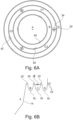
- FIGS. 2 , 3 and 6B show a schematic outline of the installation and it appears that a watertight wall 16 is arranged between two floating collars which are neighbours to each other. In a section, the wall forms a U-shape and the two edge sections of the wall are, in the longitudinal direction, fastened to two neighbouring floating collars.
- the installation can be used for general storage and treatment of water, Below is described an embodiment of the invention in which the installation is intended to be used for the farming of marine organisms.
- one can farm fish in the water reservoir A, and the sections and water reservoirs B, C and D can be used to treat the water which is supplied to the water reservoir A, and also the water that is drained from A.
- this embodiment of the invention describes a closed cage that can be placed at more exposed sites in respect to the existing closed systems of today.
- the closed cage is comprised of a flexible cloth which is impermeable to water. It is kept afloat by a primary buoyancy element which is designed according to the strength of the flexible cloth. Within this primary or first buoyancy element, a further buoyancy element is provided, and a watertight cloth is arranged between these buoyancy elements.
- a primary buoyancy element which is designed according to the strength of the flexible cloth.
- a further buoyancy element is provided, and a watertight cloth is arranged between these buoyancy elements.
- FIG. 1 shows such an embodiment of a cage installation 10.
- the cage installation 10 comprises at least one cage 12 and establishes a water volume A within the walls 14 of the cage 12. The fish is farmed in this body of water.
- the cage 12 or cage installation 10 is provided with means for leading water into the cage 12, in the figure shown with a water inlet 17. Furthermore, the cage 12 is fitted with means to lead water and waste out of the cage 12, in the figure illustrated with a water outlet 18 and an outlet 19 for wastes such as sludge, faeces, uneaten feed material, etc.
- FIG 1 shows schematically the core of the invention, i.e. that two or more floating collars are used.
- a floating collar 20 is shown, and fastened to this floating collar 20 are the walls 14 of the cage 12.
- Meant here by the term “wall” are both the vertical walls, and any inclined and horizontal wall sections in the bottom section of the cage 12.
- closed wall and closed cage is meant that the large part of the cage wall sections is water impermeable, such that one thereby prevents that water with pathogenic organisms are carried over the walls 14 and into the cage 12.
- the embodiments of the invention comprise cages 12 which are completely watertight in all wall and bottom sections.
- the cages 12 are normally open in the part facing upwards, and thus have the form of an open bag. This open upwardly facing section is often provided with a net to prevent escape and ingress of birds.
- the aim of the invention is that the cage 12 shall withstand greater strain than conventional solutions. This is achieved by using two or more floating collars which in themselves can be flexible.
- the second cage collar 20 has sufficient buoyancy to keep the cage 12 afloat under normal stresses.
- a first cage collar 22 External in relation to the second cage collar 20 is arranged a first cage collar 22.
- this first cage collar 22 has greater buoyancy properties than the second cage collar 20.
- a watertight wall 16 is arranged between the second cage collar 20 and the first cage collar 22. Between the cage collars 20,22 and the wall 16 a second water reservoir is arranged, given as B in figure 1 . This serves as a compensating body and means greater flexibility and strength in the cage arrangement 10.
- the distance (in the horizontal position) between the floating collars 20,22 can be changed when the cage 12 is subjected to forces.
- the vertical position between the floating collars 20,22 can also be altered, for example, in that the second floating collar 20 is pulled down into the water as a consequence of strain on the cage walls 14.
- the outermost floating collar 22, shown in figure 1 as the first floating collar 22 is designed so that the cage 12 is held afloat in the water and not drawn underwater.
- the wall 14 may have a different flexibility, arranged for that purpose.
- the walls may be rigid, but they can also be very flexible, for example, constructed from a cloth or tarpaulin material. The ripple effect is greatest if the cage 12 is rigid.
- a number of spacers 30 are arranged between the floating collars 20, 22. These can be elongated, somewhat flexible elements 30 which hold two floating collars 20,22 at a given distance apart and that this distance is only changed when the cage 12 and the floating collars 20,22 are subjected to external forces. In Figure 2 , they are given schematically as they extend straight across from a floating collar to another, but they may also be tilted.
- a net 28 is arranged between floating collars 20,22 such that a fish that is in the cage 12 cannot pass into the water reservoirs B, C and D.
- FIG 3 an embodiment of the invention is shown where a further floating collar 24 is arranged.
- This floating collar 24 is placed between the second floating collar 20 and the first floating collar 22.
- a bordered further water reservoir is established between each of these floating collars 20,22,24.
- this is indicated as reservoir B between the floating collars 20 and 24, and as reservoir C between the floating collars 24 and 22, and figures 6A and 6B show, in addition, a water reservoir D.
- These further water reservoirs B, C, D can be used to treat water that is supplied to or is drained from the cage 12, as explained below in more detail.
- a walkway 50 can be placed over the water reservoirs B, C, D and the floating collars 20,22,24.
- the present invention with one or more water reservoirs B, C, D, established between two floating collars 20,22,24 and the associated wall sections 16, and preferably floating externally in relation to the cage 12, provides opportunities to treat the water that shall be supplied to the cage 12. This is particularly important in recycling plants for the farming of marine organisms in which all or part of the water that is discharged out of the cage 12 via the outlet 18 is led back to the cage 12 after treatment and cleaning. However, one can also carry out a water treatment if the water is fetched from a given depth.
- a method for such water treatment is performed in that water is added to one of the water reservoirs B, C, D that is established between the floating collars 20,22,24.
- a number of openings 40 are established so that the water that flows in the water reservoir B is passed through these openings 40 and into the main water volume A of the cage 12.
- Shown in figure 4 is that if there are three floating collars 20,22,24 used, the water can be supplied to the outermost water reservoir C, and flow through the openings 42 in the floating collar 24, and further through openings 40 through the floating collar 20 to the cage 12.
- different water treatments can be carried out, such as removal of carbon dioxide, supplying of oxygen, removal of impurities, skim draining etc.
- the water reservoirs B, C, D are divided into further sections for individual water treatment in each of the sections.
- the openings 40,42 are slanted so that water is set into a rotation (flowing in only one direction) and forced into a water reservoir lying inside.
- removal of water from the cage 12 can be carried out via a sediment trap in the cage 12 and be transferred via a sedimentation pipe to an external collection and water treatment unit (not shown in detail), before the water, after treatment and before further treatment in the water reservoirs B, C, is circulated back to the cage 12.
- a cage installation 10 where the bag 12 is a cage bag 12, and where the water reservoir A is used for farming of marine organisms, one establishes a more robust installation in that there are at least two floating collars and at least two water reservoirs. Furthermore, the water that is supplied to the installation in one of the further water reservoirs B, C or D will be able to be treated (oxygenation, removal of carbon dioxide, UV disinfection, filtration, flotation, pH control, etc.).
- the water flows from the outer water reservoir, via the water reservoirs within, until it ends up in the bag 12.
- this is not mandatory as the water can also flow in the opposite direction, or also flow from, for example, reservoir D and directly into the water reservoirs B or A. Openings in the floating collars or the wall sections, and associated pipe / pipelines can lead the water flow wherever one wishes, also within externally free-floating tanks or barges.
- the water from the water reservoir A is led to one of the further water reservoirs B, C or D for purification and treatment before it is returned to the water reservoir A.
- the installation comprises at least two separate water reservoirs, it can also be used for the farming of several species at the same time.
- the installation 10 can be used for water treatment and water storage in general.
- the water reservoir A can be used for storing fresh water (subject to watertight walls 14), and the water reservoirs B, C, D can be used for water treatment such as water purification.
- the installation 10 is used to recover food matter or waste matter from the water, or for purification of water.
Landscapes
- Life Sciences & Earth Sciences (AREA)
- Environmental Sciences (AREA)
- Marine Sciences & Fisheries (AREA)
- Animal Husbandry (AREA)
- Biodiversity & Conservation Biology (AREA)
- Zoology (AREA)
- Farming Of Fish And Shellfish (AREA)
- Centrifugal Separators (AREA)
- Glass Compositions (AREA)
- Valve-Gear Or Valve Arrangements (AREA)
- Catching Or Destruction (AREA)
Claims (11)
- Schwimmende Anordnung (10), wobei die Anordnung (10) Folgendes umfasst;- einen Beutel (12) mit wasserundurchlässigen Wänden (14) zum Herstellen eines ersten Wasserbehälters (A), wobei die Wände (14) an einem ersten schwimmenden Kragen (20, 22) befestigt sind,- mindestens eine Zulaufleitung (17) für die Wasserzufuhr,- mindestens eine Ablaufleitung (18, 19) zum Abführen von Wasser und Abfall aus dem Beutel (12),- einen oder mehrere zusätzliche schwimmende Kragen (22, 24), die innerhalb oder außerhalb des ersten schwimmenden Kragens (20, 22) angeordnet sind,
wobei eine zusätzliche Wand (16) zwischen zwei benachbarten schwimmenden Kragen (20-24 oder 22-24) angeordnet ist, um bei Gebrauch im Querschnitt betrachtet eine U-Form zu bilden, sodass mindestens ein weiterer Wasserbehälter (B, C, D) hergestellt wird, wobei die zusätzliche Wand (16) wasserundurchlässig ist,- wobei der Beutel (12) ein Käfigbeutel (12) ist,
wobei der erste Wasserbehälter (A) für das Züchten von Meeresorganismen geeignet ist, und der mindestens eine weitere Wasserbehälter (B) und mögliche zusätzliche weitere Wasserbehälter (C, D) für die Behandlung von Wasser konfiguriert sind, das dem ersten Wasserbehälter (A) zuzuführen ist,- wobei in einem Abschnitt des ersten schwimmenden Kragens (20) eine Anzahl von Öffnungen (40) angeordnet ist, sodass Wasser von dem mindestens einen weiteren Wasserbehälter (B) zu dem ersten Wasserbehälter (A) fließen kann, und wobei die Anordnung vorzugsweise mehr als einen weiteren Wasserbehälter (B, C, D) umfasst, die mit Schläuchen miteinander verbunden sind, sodass man leicht die Reihenfolge der weiteren Wasserbehälter (B, C, D) wählen kann, durch die das Wasser auf seinem Weg durch die Anordnung (10) fließen soll. - Anordnung (10) nach Anspruch 1, wobei die wasserundurchlässigen Wände (14, 16) aus einem flexiblen Material wie Stoff oder Plane bestehen oder die wasserundurchlässigen Wände (14) aus einem im Wesentlichen starren Material wie Fiberglas, Stahl oder Beton bestehen oder die wasserundurchlässigen Wände (14, 16) in einigen Abschnitten aus einem starren Material und in einigen Abschnitten aus einem flexiblen Material bestehen.
- Anordnung (10) nach Anspruch 1, wobei innerhalb des ersten schwimmenden Kragens (22) eine Anzahl zusätzlicher schwimmender Kragen (20, 24) zum Herstellen der weiteren Wasserbehälter (B, C, D) bereitgestellt sind.
- Anordnung (10) nach einem der Ansprüche 1-3, wobei zwischen benachbarten schwimmenden Kragen (20, 22, 24) und der zusätzlichen Wand (16), die sich zwischen zwei solchen benachbarten schwimmenden Kragen (20, 22, 24) erstreckt, Trennwände (32) angeordnet sind, um den mindestens einen weiteren Wasserbehälter (B, C, D) in eine Anzahl von Abschnitten (B1, B2, B3, ... C1, C2, C3 ..., D1, D2, D3 ...) zu unterteilen.
- Anordnung (10) nach Anspruch 4, wobei einige der Trennwände (32) mit Öffnungen (34) für die Übertragung von Flüssigkeit und Meeresorganismen von einem Abschnitt in einen anderen ausgestattet sind.
- Anordnung (10) nach einem der Ansprüche 1-5, wobei sie mehr als einen weiteren Wasserbehälter (B, C, D) umfasst, wobei die weiteren Wasserbehälter (B, C, D) und mögliche Abschnitte für die Wasserbehandlung in einem Kreislaufsystem für Wasser konfiguriert sind.
- Anordnung (10) nach einem der Ansprüche 1-6, wobei einer oder mehrere von dem ersten und weiteren Wasserbehältern (A, B, C, D) zur Speicherung von Flüssigkeit konfiguriert sind.
- Anordnung (10) nach Anspruch 7, wobei es sich bei der in einem oder mehreren der weiteren Wasserbehälter (B, C, D) gespeicherten Flüssigkeit um eine Flüssigkeit handelt, die zur Behandlung von Meeresorganismen vorbereitet ist, vorzugsweise wobei es sich bei der Flüssigkeit um eine Flüssigkeit zur Behandlung von Parasiten handelt.
- Anordnung (10) nach Anspruch 8, wobei die Flüssigkeit Süßwasser ist, die Meeresorganismen Fische sind und die Parasiten Seeläuse sind.
- Verwendung einer Anordnung nach den Ansprüchen 1-9 zur Behandlung einer Flüssigkeit, vorzugsweise zur Wasserbehandlung, wie Sauerstoffanreicherung, Kohlendioxidentfernung, UV-Desinfektion, Filtration, Flotation und pH-Regulierung, oder zum Entfernen von Verunreinigungen aus der Flüssigkeit oder zur Rückgewinnung von Nähr- und/oder Abfallstoffen aus der Flüssigkeit.
- Verfahren zur Behandlung von Wasser, das einem ersten Wasserbehälter (A) in einem Zuchtkäfig (12) in einer Anordnung (10) nach Anspruch 1 zugeführt wird, wobeiWasser, das dem Käfig (12) zugeführt werden soll, der den ersten Wasserbehälter (A) herstellt, dem mindestens einen weiteren Wasserbehälter (B, C, d) zugeführt wird, wobeidas Wasser zu einer Fließbewegung in der Längsrichtung des mindestens einen weiteren Wasserbehälters (B, C, d) gedrängt wird, und wobei das Wasser, während es um den Käfig (12) in dem mindestens einen weiteren Wasserbehälter (B, C, D) fließt, mindestens einem Wasserbehandlungsschritt unterzogen wird, bevor das Wasser gedrängt wird, durch die Öffnungen (40) in dem ersten schwimmende Kragen (20, 22) und in den ersten Wasserbehälter (A) des Käfigs (12) zu fließen.
Applications Claiming Priority (2)
| Application Number | Priority Date | Filing Date | Title |
|---|---|---|---|
| NO20161422A NO342403B1 (no) | 2016-09-07 | 2016-09-07 | Lukket merd |
| PCT/NO2017/050220 WO2018048310A1 (en) | 2016-09-07 | 2017-09-07 | Floating arrangement for water treatment or farming of marine animals |
Publications (4)
| Publication Number | Publication Date |
|---|---|
| EP3509417A1 EP3509417A1 (de) | 2019-07-17 |
| EP3509417A4 EP3509417A4 (de) | 2020-05-13 |
| EP3509417B1 true EP3509417B1 (de) | 2025-01-15 |
| EP3509417C0 EP3509417C0 (de) | 2025-01-15 |
Family
ID=61562851
Family Applications (1)
| Application Number | Title | Priority Date | Filing Date |
|---|---|---|---|
| EP17849183.3A Active EP3509417B1 (de) | 2016-09-07 | 2017-09-07 | Schwimmende anordnung zur züchtung von meerestieren |
Country Status (4)
| Country | Link |
|---|---|
| EP (1) | EP3509417B1 (de) |
| CN (1) | CN109963463B (de) |
| NO (1) | NO342403B1 (de) |
| WO (1) | WO2018048310A1 (de) |
Families Citing this family (11)
| Publication number | Priority date | Publication date | Assignee | Title |
|---|---|---|---|---|
| WO2018151605A1 (en) | 2017-02-14 | 2018-08-23 | Rognsoey Richard | A container arrangement for fish farming |
| NO343073B1 (en) * | 2017-02-14 | 2018-10-29 | Rognsoey Richard | A container arrangement for fish farming |
| NO344276B1 (no) * | 2018-03-06 | 2019-10-28 | Searas As | Oppdrettsmerd |
| NO344542B1 (no) * | 2018-05-18 | 2020-01-27 | Kyrkjeboe Jan Erik | Fartøy for oppdrett av marine organismer |
| NO345633B1 (no) * | 2019-05-15 | 2021-05-18 | Marine Raadgivningstjenester As | Lukket, fleksibel oppdrettsmerd med flytekrage anordnet rundt en indre omkrets av merden |
| NO346399B1 (no) * | 2021-05-07 | 2022-07-11 | Fish Care Systems As | Lukket oppdrettsmerd for oppdrett av fisk samt fremgangsmåte for avgrensing av flere vannvolumer i en lukket oppdrettsmerd |
| NO347536B1 (en) * | 2021-05-14 | 2023-12-18 | Sfs Group As | Fish farming cage and method for exchanging water in a fish farming cage. |
| NO346372B1 (no) * | 2021-06-16 | 2022-06-27 | Ecomerden As | Semilukket eller lukket merdkonstruksjon |
| CN114145251A (zh) * | 2021-12-21 | 2022-03-08 | 中国华能集团清洁能源技术研究院有限公司 | 一种漂浮封闭网箱式海上牧场 |
| CN115053855B (zh) * | 2022-07-19 | 2023-04-25 | 浙江省海洋水产研究所 | 一种提高海捕野生梭子蟹暂养成活率的养殖池 |
| CN117356499B (zh) * | 2023-11-09 | 2026-01-09 | 中船黄埔文冲船舶有限公司 | 深海水产养殖舱结构 |
Family Cites Families (15)
| Publication number | Priority date | Publication date | Assignee | Title |
|---|---|---|---|---|
| US3635347A (en) * | 1969-08-15 | 1972-01-18 | Edward J Rupnick | Apparatus for controlling the dispersion of pollutants floating on a body of water |
| GB1409926A (en) * | 1972-11-21 | 1975-10-15 | Castell W G | Means and method for disposal of effluents |
| SE450988B (sv) * | 1986-01-27 | 1987-08-24 | Farmocean Ab | Flytande odlingsanleggning for fisk med anordningar for uppdelning i flera mindre odlingsvolymer |
| GB2200822B (en) * | 1987-02-11 | 1991-01-30 | Ragnar Vadseth | Farming enclosures |
| JPH0310626A (ja) * | 1989-06-08 | 1991-01-18 | Tokuzo Hirose | 水上導水路、水上貯水槽、複合的水上導水路、海上水田装置、水上水耕栽培農園装置および船 |
| CA2075442A1 (en) * | 1992-08-06 | 1994-02-07 | Jean-Claude Desrosiers | Fish breeding system with separate breeding and sedimentation tanks |
| NO980086L (no) * | 1998-01-08 | 1999-07-09 | Norsk Marinteknisk Forskningsi | Nedsenkbar fiskemerd |
| AUPP178398A0 (en) * | 1998-02-11 | 1998-03-05 | Mcrobert, Ian | Apparatus and method for lifting a net of an aquaculture pen and an aquaculture pen incorporating same |
| JP2003138612A (ja) * | 2001-11-02 | 2003-05-14 | Hiroshi Okawa | 水上貯水タンクおよび集水装置 |
| CA2571439A1 (en) * | 2004-06-25 | 2006-01-05 | Ian Mcrobert | Aquaculture system |
| US7674378B2 (en) * | 2006-12-19 | 2010-03-09 | Modular Wetland Systems, Inc. | Wetland water treatment system |
| GB2491500A (en) * | 2009-12-14 | 2012-12-05 | Ocean Solutions As | System and method for treating fish |
| EP2587915B1 (de) * | 2010-04-22 | 2015-01-14 | Ecomerden A/S | Fischzuchtfarm und wasserflussverfahren für eine fischzuchtfarm |
| CN102210274B (zh) * | 2011-06-10 | 2013-04-17 | 浙江海洋学院 | 高效养殖网箱 |
| CN204949124U (zh) * | 2015-07-27 | 2016-01-13 | 广东联塑科技实业有限公司 | 一种养殖网箱支架 |
-
2016
- 2016-09-07 NO NO20161422A patent/NO342403B1/no unknown
-
2017
- 2017-09-07 WO PCT/NO2017/050220 patent/WO2018048310A1/en not_active Ceased
- 2017-09-07 EP EP17849183.3A patent/EP3509417B1/de active Active
- 2017-09-07 CN CN201780054980.5A patent/CN109963463B/zh active Active
Also Published As
| Publication number | Publication date |
|---|---|
| EP3509417A4 (de) | 2020-05-13 |
| NO342403B1 (no) | 2018-05-14 |
| CN109963463A (zh) | 2019-07-02 |
| WO2018048310A1 (en) | 2018-03-15 |
| EP3509417A1 (de) | 2019-07-17 |
| EP3509417C0 (de) | 2025-01-15 |
| NO20161422A1 (no) | 2018-03-08 |
| CN109963463B (zh) | 2022-10-11 |
Similar Documents
| Publication | Publication Date | Title |
|---|---|---|
| EP3509417B1 (de) | Schwimmende anordnung zur züchtung von meerestieren | |
| US11840318B2 (en) | Vessel for farming of marine organisms | |
| EP2587915B1 (de) | Fischzuchtfarm und wasserflussverfahren für eine fischzuchtfarm | |
| US8641893B2 (en) | Floating cell and island with a floating macrophyte filter | |
| CA2849676C (en) | Fish farming plant, module, method and use | |
| JP2019512223A (ja) | 半潜水型養殖システム | |
| NO344466B1 (en) | A floating fish farming plant and assembly of plants | |
| EP4436370B1 (de) | Offshore-fischfarm | |
| CN109068618B (zh) | 用于鱼类养殖的装置和方法 | |
| NO345877B1 (en) | Aquaculture fish pen system and related method | |
| US20250049003A1 (en) | Pump and cleaning system for fish farm | |
| NO20110331A1 (no) | Flytende lukket oppdrettsanlegg | |
| DK202530484A1 (en) | Floating closed or semi-closed fish farm | |
| CN1697783A (zh) | 水质污浊防止方法及水流隔断墙 | |
| Pirozzi et al. | Aquaculture Systems Design | |
| NO20250663A1 (en) | Fish farm and associated methods | |
| KR101277804B1 (ko) | 인공 구조물을 이용한 보릿짚 계류장치 | |
| CN117441658A (zh) | 一种柔性半潜式封闭循环水养殖装备 | |
| DD228438A1 (de) | Vorrichtung zur fischproduktion in schwimmenden behaeltern mit abwasserreinigung | |
| CZ2019317A3 (cs) | Zařízení pro zachycení sedimentů, zejména na přítoku do vodních nádrží | |
| CA3067662A1 (en) | Floating, closed, self-supporting fish-farming cage comprising a tubular membrane made of a polymer with high mechanical strength and low biofouling adhesion, and system of fish-farming cages |
Legal Events
| Date | Code | Title | Description |
|---|---|---|---|
| STAA | Information on the status of an ep patent application or granted ep patent |
Free format text: STATUS: THE INTERNATIONAL PUBLICATION HAS BEEN MADE |
|
| PUAI | Public reference made under article 153(3) epc to a published international application that has entered the european phase |
Free format text: ORIGINAL CODE: 0009012 |
|
| STAA | Information on the status of an ep patent application or granted ep patent |
Free format text: STATUS: REQUEST FOR EXAMINATION WAS MADE |
|
| 17P | Request for examination filed |
Effective date: 20190408 |
|
| AK | Designated contracting states |
Kind code of ref document: A1 Designated state(s): AL AT BE BG CH CY CZ DE DK EE ES FI FR GB GR HR HU IE IS IT LI LT LU LV MC MK MT NL NO PL PT RO RS SE SI SK SM TR |
|
| AX | Request for extension of the european patent |
Extension state: BA ME |
|
| DAV | Request for validation of the european patent (deleted) | ||
| DAX | Request for extension of the european patent (deleted) | ||
| A4 | Supplementary search report drawn up and despatched |
Effective date: 20200409 |
|
| RIC1 | Information provided on ipc code assigned before grant |
Ipc: A01K 63/04 20060101ALI20200403BHEP Ipc: A01K 61/13 20170101ALI20200403BHEP Ipc: A01K 61/60 20170101AFI20200403BHEP |
|
| STAA | Information on the status of an ep patent application or granted ep patent |
Free format text: STATUS: EXAMINATION IS IN PROGRESS |
|
| 17Q | First examination report despatched |
Effective date: 20231129 |
|
| GRAP | Despatch of communication of intention to grant a patent |
Free format text: ORIGINAL CODE: EPIDOSNIGR1 |
|
| STAA | Information on the status of an ep patent application or granted ep patent |
Free format text: STATUS: GRANT OF PATENT IS INTENDED |
|
| INTG | Intention to grant announced |
Effective date: 20240814 |
|
| GRAS | Grant fee paid |
Free format text: ORIGINAL CODE: EPIDOSNIGR3 |
|
| GRAA | (expected) grant |
Free format text: ORIGINAL CODE: 0009210 |
|
| STAA | Information on the status of an ep patent application or granted ep patent |
Free format text: STATUS: THE PATENT HAS BEEN GRANTED |
|
| AK | Designated contracting states |
Kind code of ref document: B1 Designated state(s): AL AT BE BG CH CY CZ DE DK EE ES FI FR GB GR HR HU IE IS IT LI LT LU LV MC MK MT NL NO PL PT RO RS SE SI SK SM TR |
|
| REG | Reference to a national code |
Ref country code: CH Ref legal event code: EP Ref country code: GB Ref legal event code: FG4D |
|
| REG | Reference to a national code |
Ref country code: DE Ref legal event code: R096 Ref document number: 602017087379 Country of ref document: DE |
|
| REG | Reference to a national code |
Ref country code: IE Ref legal event code: FG4D |
|
| U01 | Request for unitary effect filed |
Effective date: 20250214 |
|
| U07 | Unitary effect registered |
Designated state(s): AT BE BG DE DK EE FI FR IT LT LU LV MT NL PT RO SE SI Effective date: 20250220 |
|
| PG25 | Lapsed in a contracting state [announced via postgrant information from national office to epo] |
Ref country code: RS Free format text: LAPSE BECAUSE OF FAILURE TO SUBMIT A TRANSLATION OF THE DESCRIPTION OR TO PAY THE FEE WITHIN THE PRESCRIBED TIME-LIMIT Effective date: 20250415 |
|
| PG25 | Lapsed in a contracting state [announced via postgrant information from national office to epo] |
Ref country code: PL Free format text: LAPSE BECAUSE OF FAILURE TO SUBMIT A TRANSLATION OF THE DESCRIPTION OR TO PAY THE FEE WITHIN THE PRESCRIBED TIME-LIMIT Effective date: 20250115 |
|
| PG25 | Lapsed in a contracting state [announced via postgrant information from national office to epo] |
Ref country code: ES Free format text: LAPSE BECAUSE OF FAILURE TO SUBMIT A TRANSLATION OF THE DESCRIPTION OR TO PAY THE FEE WITHIN THE PRESCRIBED TIME-LIMIT Effective date: 20250115 |
|
| PG25 | Lapsed in a contracting state [announced via postgrant information from national office to epo] |
Ref country code: IS Free format text: LAPSE BECAUSE OF FAILURE TO SUBMIT A TRANSLATION OF THE DESCRIPTION OR TO PAY THE FEE WITHIN THE PRESCRIBED TIME-LIMIT Effective date: 20250515 |
|
| PGFP | Annual fee paid to national office [announced via postgrant information from national office to epo] |
Ref country code: NO Payment date: 20250624 Year of fee payment: 9 |
|
| PG25 | Lapsed in a contracting state [announced via postgrant information from national office to epo] |
Ref country code: HR Free format text: LAPSE BECAUSE OF FAILURE TO SUBMIT A TRANSLATION OF THE DESCRIPTION OR TO PAY THE FEE WITHIN THE PRESCRIBED TIME-LIMIT Effective date: 20250115 |
|
| PG25 | Lapsed in a contracting state [announced via postgrant information from national office to epo] |
Ref country code: GR Free format text: LAPSE BECAUSE OF FAILURE TO SUBMIT A TRANSLATION OF THE DESCRIPTION OR TO PAY THE FEE WITHIN THE PRESCRIBED TIME-LIMIT Effective date: 20250416 |
|
| U20 | Renewal fee for the european patent with unitary effect paid |
Year of fee payment: 9 Effective date: 20250701 |
|
| PG25 | Lapsed in a contracting state [announced via postgrant information from national office to epo] |
Ref country code: SM Free format text: LAPSE BECAUSE OF FAILURE TO SUBMIT A TRANSLATION OF THE DESCRIPTION OR TO PAY THE FEE WITHIN THE PRESCRIBED TIME-LIMIT Effective date: 20250115 |
|
| PGFP | Annual fee paid to national office [announced via postgrant information from national office to epo] |
Ref country code: GB Payment date: 20250919 Year of fee payment: 9 |
|
| PG25 | Lapsed in a contracting state [announced via postgrant information from national office to epo] |
Ref country code: CZ Free format text: LAPSE BECAUSE OF FAILURE TO SUBMIT A TRANSLATION OF THE DESCRIPTION OR TO PAY THE FEE WITHIN THE PRESCRIBED TIME-LIMIT Effective date: 20250115 |
|
| PG25 | Lapsed in a contracting state [announced via postgrant information from national office to epo] |
Ref country code: SK Free format text: LAPSE BECAUSE OF FAILURE TO SUBMIT A TRANSLATION OF THE DESCRIPTION OR TO PAY THE FEE WITHIN THE PRESCRIBED TIME-LIMIT Effective date: 20250115 |
|
| PLBE | No opposition filed within time limit |
Free format text: ORIGINAL CODE: 0009261 |
|
| STAA | Information on the status of an ep patent application or granted ep patent |
Free format text: STATUS: NO OPPOSITION FILED WITHIN TIME LIMIT |
|
| 26N | No opposition filed |
Effective date: 20251016 |