EP3509163A1 - Leiteranschlussklemme - Google Patents
Leiteranschlussklemme Download PDFInfo
- Publication number
- EP3509163A1 EP3509163A1 EP19150508.0A EP19150508A EP3509163A1 EP 3509163 A1 EP3509163 A1 EP 3509163A1 EP 19150508 A EP19150508 A EP 19150508A EP 3509163 A1 EP3509163 A1 EP 3509163A1
- Authority
- EP
- European Patent Office
- Prior art keywords
- actuating
- recess
- conductor
- groove
- conductor terminal
- Prior art date
- Legal status (The legal status is an assumption and is not a legal conclusion. Google has not performed a legal analysis and makes no representation as to the accuracy of the status listed.)
- Granted
Links
Images



Classifications
-
- H—ELECTRICITY
- H01—ELECTRIC ELEMENTS
- H01R—ELECTRICALLY-CONDUCTIVE CONNECTIONS; STRUCTURAL ASSOCIATIONS OF A PLURALITY OF MUTUALLY-INSULATED ELECTRICAL CONNECTING ELEMENTS; COUPLING DEVICES; CURRENT COLLECTORS
- H01R4/00—Electrically-conductive connections between two or more conductive members in direct contact, i.e. touching one another; Means for effecting or maintaining such contact; Electrically-conductive connections having two or more spaced connecting locations for conductors and using contact members penetrating insulation
- H01R4/28—Clamped connections, spring connections
- H01R4/48—Clamped connections, spring connections utilising a spring, clip, or other resilient member
- H01R4/4809—Clamped connections, spring connections utilising a spring, clip, or other resilient member using a leaf spring to bias the conductor toward the busbar
- H01R4/48185—Clamped connections, spring connections utilising a spring, clip, or other resilient member using a leaf spring to bias the conductor toward the busbar adapted for axial insertion of a wire end
- H01R4/4819—Clamped connections, spring connections utilising a spring, clip, or other resilient member using a leaf spring to bias the conductor toward the busbar adapted for axial insertion of a wire end the spring shape allowing insertion of the conductor end when the spring is unbiased
- H01R4/4821—Single-blade spring
-
- H—ELECTRICITY
- H01—ELECTRIC ELEMENTS
- H01R—ELECTRICALLY-CONDUCTIVE CONNECTIONS; STRUCTURAL ASSOCIATIONS OF A PLURALITY OF MUTUALLY-INSULATED ELECTRICAL CONNECTING ELEMENTS; COUPLING DEVICES; CURRENT COLLECTORS
- H01R4/00—Electrically-conductive connections between two or more conductive members in direct contact, i.e. touching one another; Means for effecting or maintaining such contact; Electrically-conductive connections having two or more spaced connecting locations for conductors and using contact members penetrating insulation
- H01R4/28—Clamped connections, spring connections
- H01R4/48—Clamped connections, spring connections utilising a spring, clip, or other resilient member
- H01R4/4809—Clamped connections, spring connections utilising a spring, clip, or other resilient member using a leaf spring to bias the conductor toward the busbar
- H01R4/4828—Spring-activating arrangements mounted on or integrally formed with the spring housing
- H01R4/4833—Sliding arrangements, e.g. sliding button
-
- H—ELECTRICITY
- H01—ELECTRIC ELEMENTS
- H01R—ELECTRICALLY-CONDUCTIVE CONNECTIONS; STRUCTURAL ASSOCIATIONS OF A PLURALITY OF MUTUALLY-INSULATED ELECTRICAL CONNECTING ELEMENTS; COUPLING DEVICES; CURRENT COLLECTORS
- H01R4/00—Electrically-conductive connections between two or more conductive members in direct contact, i.e. touching one another; Means for effecting or maintaining such contact; Electrically-conductive connections having two or more spaced connecting locations for conductors and using contact members penetrating insulation
- H01R4/28—Clamped connections, spring connections
- H01R4/48—Clamped connections, spring connections utilising a spring, clip, or other resilient member
- H01R4/4809—Clamped connections, spring connections utilising a spring, clip, or other resilient member using a leaf spring to bias the conductor toward the busbar
- H01R4/4846—Busbar details
- H01R4/485—Single busbar common to multiple springs
Definitions
- the invention relates to a conductor terminal with an insulating housing, a clamping spring for clamping an electrical conductor and an actuating pushbutton, which is displaceably mounted in the insulating housing and an actuating portion for acting on the clamping spring and an accessible from the outside of the insulating housing actuating push head with a recess for receiving an actuating tool Has.
- Such conductor terminals are known in many forms and are, for example, used as terminal blocks.
- DE 10 2015 120 063 B3 shows such a conductor terminal with a pusher, which has an actuating shaft for receiving an actuating tool.
- the actuating shaft opens into a receiving slot.
- the actuating head has in this way a funnel-shaped depression, which leads in the central region with the passage opening to the clamping spring.
- DE 10 2007 050 683 B4 discloses a conductor terminal with a tiltably mounted in a guide channel actuating push-button.
- the actuating push-button has on its actuating push-button a recess for receiving the actuating tool, which is slit-shaped or cross-shaped.
- the bottom of the depression is flat.
- DE 10 2013 104 394 A1 shows a conductor terminal with an actuating push-button, which has a groove-shaped recess at its actuating push head, which merges on one side in a spherical recess.
- the recess on the actuating push head has an increasing depth from the central area to the edge areas.
- the force acting on the actuating lever from the operating force is directed substantially in the direction of the longitudinal axis of the actuating lever, even if the actuating tool is not exactly in the alignment of the actuating lever in the direction of extension of the longitudinal axis, but obliquely attached thereto. This prevents the actuating push-button from becoming excessively inclined and possibly abutting components of the conductor connection terminal, such as, for example, a busbar.
- the recess may be groove-shaped (and thus forms a groove-shaped contour section on the actuating push-button).
- the groove bottom of the recess is formed extending from the diametrically opposite edge regions of the groove-shaped depression to the common central region obliquely to the end face of the actuating push head towards.
- the groove-shaped recess is thus as a slot or designed as a groove, the groove bottom is not flat (ie horizontal plan), but from the opposite edge regions to the common central region has sloping sections.
- the actuator head may also have a shaped recess, e.g. is cylindrical or frusto-conical or formed in any other suitable form, which projects beyond the groove-shaped contour portion of the recess.
- the recess is thus formed on the one hand by the slot and on the other hand by the recess leading into the slot and laterally widening the slot.
- a cross-sectionally round actuating tool such as. A Phillips screwdriver.
- the recess may be central and lie in the alignment of the central or central axis of the actuating handle.
- the depression may have a convexly curved bottom plane.
- the bottom surfaces of the ground plane are curved and not straight as in a triangular or trapezoidal cross-section.
- An obliquely attached actuating tool can thus rest only at one point of the ground plane, in order to ensure in this way an acting at the sharpest possible angle to the longitudinal extension direction of the actuating lever actuating force on the actuating lever.
- the recess can also have a trapezoidal or triangular tapered bottom plane in cross section.
- the ground plane which tapers in a triangular cross-section, runs relatively pointedly in the central area.
- the trapezoidal in cross-section ground level has a flat platform in the central region, which is transverse to the longitudinal direction of the actuating lever. When placing the operating tool on this platform in the central region, the actuating force is then applied perpendicular to the platform in the longitudinal extension direction of the actuating handle, so that in this way tilting of the actuating handle is avoided.
- the actuating tool obliquely acts on the adjacent to the platform inclined surfaces of the trapezoidal in cross-section depression, then the actuating force is still deflected substantially in the longitudinal direction of the actuating lever and a too strong Tilting of the actuating handle in comparison to a generally flat bottom plane prevented.
- the depression can also have a pyramid-shaped, truncated pyramidal, conical, frusto-conical or paraboloidal protruding toward the end face of the actuating push-head.
- the bottom sloping toward the edge portions of the recess is provided not only two-dimensionally as in a groove-shaped recess, but three-dimensionally. The risk of tilting or tilting of the actuating handle when moving in a pusher channel of the insulating material is further reduced in this way.
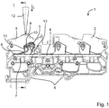
- FIG. 1 shows a side view of a conductor terminal 1 in the form of a terminal block.
- the conductor connection terminal 1 has an insulating material housing 2 with conductor connections for connecting electrical conductors. These are guided in conductor insertion channels of the insulating housing 2 to a terminal point, which is formed of a clamping spring 3 and a bus bar 4.
- the bus bar 4 has openings for insertion of an electrical conductor.
- a clamping spring 3 is suspended in each case in one of these openings in order to clamp with a clamping leg 6 an inserted into a conductor insertion channel 5 electrical conductor to a clamping edge of the busbar 4.
- the bus bar 4 in the region of a respective clamping spring 3 has a so-called material passage, protrude at the guide walls 7 at the conductor insertion channel 5 diametrically opposite bottom of the bus bar 4.
- This is a guide channel for the electrical conductor formed and the current cross section for deriving the current from the electrical conductor via the terminal point in the busbar 4 increases.
- the insulating housing 2 has at the bottom, for example, a snap-in foot 8, with which the insulating material 2 on a mounting rail (not shown) can be snapped.
- an actuating channel 9 is introduced in each case in addition to a conductor insertion channel 5, each of which leads to the clamping leg 6, a clamping spring 3 and opens out there.
- an actuating lever 10 is slidably mounted in the longitudinal direction L of the actuating lever 10.
- the actuating push-button 10 only one actuating portion 11 which is mounted on the clamping leg 6 to act on the clamping spring 6 can be seen in the side view.
- the actuating handle 10 is accessible from the outside of the insulating housing 2, so that an actuating tool 12 as shown on the operating handle head (not visible) can be placed.
- actuating force of the actuating lever 10 can now be displaced in the longitudinal direction L to the busbar 4 out.
- the actuating leg 6 of the clamping spring 3 is moved against the spring force of the clamping spring 3 to the opposite bearing leg 13 of the clamping spring 3 and opened between the end of the clamping leg 6 and the clamping edge of the busbar 4 clamping point for clamping an electrical conductor.
- an electrical conductor inserted force-free and vice versa a clamped electrical conductor removed again and pulled out of the conductor insertion channel 5 of the insulating material 2.
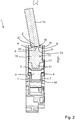
- FIG. 2 shows a sectional view of the conductor terminal 1 from FIG. 1 , It is now clear that the actuating lever 10 has a tapered actuating portion 11 at its lower end. This is designed to immerse in the conductor receiving opening 14 of the busbar 4, when the clamping leg 6 of the clamping spring. 3 is also pressed into the conductor receiving opening 14 with the actuating handle 10 in the longitudinal direction L of the actuating lever 10 down.
- actuating lever 10 is mounted longitudinally displaceable in an actuating channel 9 of the insulating housing 2.
- the actuating push-button 10 has in the transition of the actuating portion 11 to the central portion 16 of the actuating handle stop lugs 17, which together with the insulating 2 form a stop and slipping out of the actuating lever 10 of the insulating material upwards, i. opposite to the illustrated longitudinal direction L prevents.
- the actuating lever 10 has an actuating push-button head 18 at its end diametrically opposite the actuating section 11.
- actuating push-button head 18 On the front side of the actuating push head 18, a recess 19 is introduced, in which the front end of an actuating tool 12, such as a flat-head screwdriver, can dip.
- the depression has an increasing depth from the central region Z to the diametrically opposite edge regions R of the depression 19.
- the bottom of the recess 19 is thus convexly curved or as in the example shown designed to be precisely trapezoidal in cross section.
- the central region Z is designed as a transverse to the longitudinal direction L of the actuating lever 10 just trained platform 20. To this flat platform 20 are followed right and left each sloping surface portions 21 at.
- the recess 19 is groove-shaped in the illustrated embodiment, i. it is in the illustrated section from left to right oblong and transverse to the illustrated cutting direction relatively narrow with straight or slightly inclined side walls.
- the inclined sloping surfaces of the bottom which are directed towards the central area in the direction of the outer face of the actuating push-button head, i. the surface portions 21, ensure that the actuating lever 10 is tilted much less from the longitudinal direction L at its displacements in the direction of the busbar 4, as would be the case without this specific contour of the recess 19. This ensures that the actuating portion 11 actually dips into the conductor receiving opening 14 of the busbar 4 and not tilted on the busbar 4.
- FIG. 3 shows a side view of the conductor terminal 1 FIG. 1 ,
- the actuating tool 12 is now further pressed into the insulating housing 2 to shift the actuating lever 10 in the direction of the busbar 4 and the clamping leg 6 counteracting the spring force of the clamping spring 3 to press the opposite plant leg 13 out.
- the terminal point is opened for clamping an electrical conductor.
- FIG. 4 shows a sectional view in section in the in the FIG. 3 sketched section DD. It can now be seen that the actuating push-button 10 is depressed in the longitudinal direction L to the busbar 4 down. The operating portion 11 now dips into the conductor receiving opening 14 of the busbar 4 together with the clamping leg 6 of the clamping spring 3 a. It is clear that the actuating lever 10 in this case is tilted slightly to the longitudinal direction L and the longitudinal axis of the actuating channel 9.
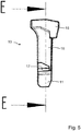
- FIG. 5 shows a side view of the actuating handle 10 of the conductor terminal 1 of the above-described figures.
- the actuating trigger 10 has an actuating trigger head 18 with a cross-section widening from the central portion 16 of the actuating trigger 10.
- the operating handle head 18 collar-like projections, which can be guided into the correspondingly shaped actuating channel 9 of the insulating housing 2.
- the actuating lever 10 has a subsequent to the central portion 16 actuating portion 11 which tapers towards the free end. Visible is also the web-like stop 17 on one side of the actuating lever 10. On the non-visible opposite side is also a corresponding web-like stop lug 17 is present.
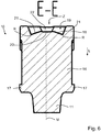
- FIG. 6 shows a sectional view of the actuating lever 10 from FIG. 5 in the section line EE shown there. It is clear that the actuating portion 11 tapers conically at the free end of the actuating lever 10. Furthermore, in the transition between the actuating portion 11 and the central portion 16 laterally projecting stop lugs 17 are present, which extend in the direction of the web.
- the actuating push head 18 has at its upper end a groove-shaped in the section EE from left to right slit-like extending recess 19 in the central region of the recess 19 is in addition to the actuating portion 11 diametrically opposite side of the actuating lever introduced a frusto-conical central recess 22, which as sketched in the direction of view on the groove-shaped contour protrudes the recess 19.
- the recess 19 is thus formed in the central region Z substantially by the frusto-conical recess 22 and in the edge regions R by the groove-shaped contour with sloping to the edge regions R down ground levels.
- a flat platform 20 is present in the central region Z of the recess 19, a flat platform 20 is present.
- the plane of the platform 20 is transverse to the longitudinal direction L of the actuating lever 10.
- An actuating force acting there thus acts essentially in the longitudinal direction L on the central axis M of the actuating lever 10th
- FIG. 7 shows a perspective view of the actuating lever 10 from Figures 5 and 6 , It is clear that the recess 19 is groove-shaped and has a transversely extending in the actuating head 18 slot. In the central region, the recess 19 also has the frusto-conical recess 22 which widens the groove-shaped contour of the recess 19 laterally out of the slot. This central recess 22 thus projects laterally beyond the groove-shaped contour section of the recess 19 on both sides and, moreover, merges into the slot-shaped groove.
Landscapes
- Connections Arranged To Contact A Plurality Of Conductors (AREA)
Abstract
Description
- Die Erfindung betrifft eine Leiteranschlussklemme mit einem Isolierstoffgehäuse, einer Klemmfeder zum Anklemmen eines elektrischen Leiters und einem Betätigungsdrücker, der verschiebbar in dem Isolierstoffgehäuse gelagert ist und einen Betätigungsabschnitt zur Beaufschlagung der Klemmfeder und einen von der Außenseite des Isolierstoffgehäuses zugänglichen Betätigungsdrückerkopf mit einer Vertiefung zur Aufnahme eines Betätigungswerkzeuges hat.
- Solche Leiteranschlussklemmen sind in vielfältiger Form bekannt und werden bspw. als Reihenklemmen verwendet.
-
DE 10 2015 120 063 B3 zeigt eine solche Leiteranschlussklemme mit einem Drücker, der einen Betätigungsschacht zur Aufnahme eines Betätigungswerkzeuges hat. Der Betätigungsschacht mündet in einem Aufnahmeschlitz aus. Der Betätigungsdrückerkopf hat auf diese Weise eine trichterförmige Vertiefung, die im zentralen Bereich mit der Durchgangsöffnung zur Klemmfeder führt. -
DE 10 2007 050 683 B4 offenbart eine Leiteranschlussklemme mit einem verkippbar in einem Führungskanal gelagerten Betätigungsdrücker. Der Betätigungsdrücker hat an seinem Betätigungsdrückerkopf eine Vertiefung zur Aufnahme des Betätigungswerkzeuges, die schlitzförmig oder kreuzschlitzförmig ausgebildet ist. Der Boden der Vertiefung ist eben. -
DE 10 2013 104 394 A1 zeigt eine Leiteranschlussklemme mit einem Betätigungsdrücker, der an seinem Betätigungsdrückerkopf eine nutförmige Vertiefung hat, die an einer Seite in eine kugelförmige Vertiefung übergeht. -
DE 298 19 517 U1 zeigt eine Zugfederanschlussklemme mit einer Verriegelungsaufnahme, die eine nutförmige Steckaufnahme mit einem an das freie Ende eines Schraubendrehers angepassten V-förmigen Öffnungswinkel aufweist. - Ausgehend hiervon ist es Aufgabe der vorliegenden Erfindung, eine verbesserte Leiteranschlussklemme zu schaffen, die eine zuverlässigere Führung des Betätigungsdrückers bei Beaufschlagung mit einem Betätigungswerkzeug sicherstellt.
- Die Aufgabe wird mit der Leiteranschlussklemme mit den Merkmalen des Anspruchs 1 gelöst. Vorteilhafte Ausführungsformen sind in den Unteransprüchen beschrieben.
- Es wird vorgeschlagen, dass die Vertiefung am Betätigungsdrückerkopf eine vom zentralen Bereich zu den Randbereichen zunehmende Tiefe hat. Damit wird die von dem Betätigungswerkzeug auf den Betätigungsdrücker einwirkende Kraft im Wesentlichen in die Richtung der Längsachse des Betätigungsdrückers gelenkt, auch wenn das Betätigungswerkzeug nicht exakt in der Flucht des Betätigungsdrückers in Erstreckungsrichtung der Längsachse, sondern schräg hierzu angesetzt wird. Damit wird verhindert, dass sich der Betätigungsdrücker ungewollt zu stark schräg stellt und gegebenenfalls an Bauteilen der Leiteranschlussklemme, wie bspw. einer Stromschiene anstößt.
- Dies gelingt durch Schrägflächen des Bodens, d.h. durch Ausformung der Bodenebene der Vertiefung mit der Folge, dass der zentrale Bereich der Vertiefung eine geringere Tiefe als die Randbereiche der Vertiefung hat. Diese Flächen werden im Weiteren als Bodenflächen oder Flächenabschnitte bezeichnet.
- Die Vertiefung kann nutförmig sein (und bildet damit einen nutenförmigen Konturabschnitt am Betätigungsdrücker). Der Nutgrund der Vertiefung ist dabei von den einander diametral gegenüberliegenden Randbereichen der nutförmigen Vertiefung zum gemeinsamen zentralen Bereich schräg zur Stirnseite des Betätigungsdrückerkopfes hin verlaufend ausgebildet. Die nutförmige Vertiefung ist somit als Schlitz bzw. als Nut ausgeführt, dessen Nutgrund nicht eben (d.h. horizontal plan) ist, sondern von den einander gegenüberliegenden Randbereichen zum gemeinsamen zentralen Bereich hin schräg verlaufende Abschnitte hat.
- Der Betätigungsdrückerkopf kann zudem noch eine geformte Ausnehmung haben, die z.B. zylinderförmig oder kegelstumpfförmig oder in anderer geeigneter Form gebildet ist, die über den nutförmigen Konturabschnitt der Vertiefung hinausragt. Die Vertiefung wird somit einerseits durch den Schlitz und andererseits durch die in den Schlitz hineinführende und den Schlitz seitlich verbreiternde Ausnehmung gebildet. Mit einer solchen zusätzlichen Ausnehmung wird zusätzlich die Betätigung durch ein im Querschnitt rundes Betätigungswerkzeug, wie bspw. einen Kreuzschraubendreher ermöglicht. Die Ausnehmung kann zentral sein und in der Flucht der Mittel- bzw. Zentralachse des Betätigungsdrückers liegen.
- Die Vertiefung kann eine konvex gewölbte Bodenebene haben. Die Bodenflächen der Bodenebene sind dabei gekrümmt und nicht wie bei einem dreieck- oder trapezförmigen Querschnitt geradlinig. Ein schräg angesetztes Betätigungswerkzeug kann damit nur an einem Punkt der Bodenebene aufliegen, um auf diese Weise eine im möglichst spitzen Winkel zur Längserstreckungsrichtung des Betätigungsdrückers wirkende Betätigungskraft auf den Betätigungsdrücker sicherzustellen.
- Die Vertiefung kann aber auch eine im Querschnitt trapezförmig oder dreieckförmig zulaufende Bodenebene haben. Die im Querschnitt dreieckförmig zulaufende Bodenebene läuft im zentralen Bereich relativ spitz aus. Die im Querschnitt trapezförmig zulaufende Bodenebene hat hingegen im zentralen Bereich eine ebene Plattform, die quer zur Längserstreckungsrichtung des Betätigungsdrückers steht. Beim Aufsetzen des Betätigungswerkzeuges auf diese Plattform im zentralen Bereich wird die Betätigungskraft dann lotrecht zur Plattform in Längserstreckungsrichtung des Betätigungsdrückers ausgeübt, sodass auf diese Weise ein Verkippen des Betätigungsdrückers vermieden wird. Wenn das Betätigungswerkzeug schräg auf die sich an die Plattform anschließenden Schrägflächen der im Querschnitt trapezförmigen Vertiefung wirkt, dann wird die Betätigungskraft immer noch im Wesentlichen in die Längserstreckungsrichtung des Betätigungsdrückers umgelenkt und ein zu starkes Verkippen des Betätigungsdrückers im Vergleich zu einer insgesamt ebenen Bodenebene verhindert.
- Die Vertiefung kann aber auch einen zur Stirnseite des Betätigungsdrückerkopfes hin pyramidenförmig, pyramidenstumpfförmig, kegelförmig, kegelstumpfförmig oder paraboloidförmig abragenden Boden haben. Bei dieser Ausführungsform wird der zu den Randbereichen der Vertiefung hin schräg verlaufende Boden nicht nur zweidimensional wie bei einer nutförmigen Vertiefung, sondern dreidimensional bereitgestellt. Die Gefahr eines Verkippens oder Verkantens des Betätigungsdrückers beim Verschieben in einem Drückerkanal des Isolierstoffgehäuses wird auf diese Weise noch weiter verringert.
- Die Erfindung wird nachfolgend anhand eines Ausführungsbeispiels mit den beigefügten Zeichnungen näher erläutert. Es zeigen:
- Figur 1
- - Seitenansicht einer Leiteranschlussklemme mit Betätigungswerkzeug in der Schnittlinie C-C;
- Figur 2
- - Schnittansicht der Leiteranschlussklemme aus
Figur 1 im Schnitt C-C; - Figur 3
- - Seitenansicht der Leiteranschlussklemme aus
Figur 1 mit Betätigungswerkzeug in der heruntergedrückten Stellung des Betätigungsdrückers in der Schnittlinie D-D; - Figur 4
- - Schnittansicht der Leiteranschlussklemme aus
Figur 3 im Schnitt D-D; - Figur 5
- - Seitenansicht des Betätigungsdrückers für die Leiteranschlussklemme aus
Figuren 1 bis 4 mit der Schnittlinie E-E; - Figur 6
- - Schnittansicht des Betätigungsdrückers aus
Figur 5 im Schnitt E-E; - Figur 7
- - Perspektivische Darstellung des Betätigungsdrückers aus
Figuren 5 und6 . -
Figur 1 zeigt eine Seitenansicht einer Leiteranschlussklemme 1 in Form einer Reihenklemme. Die Leiteranschlussklemme 1 hat ein Isolierstoffgehäuse 2 mit Leiteranschlüssen zum Anklemmen elektrischer Leiter. Diese werden in Leitereinführungskanäle des Isolierstoffgehäuses 2 zu einer Klemmstelle hin geführt, die aus einer Klemmfeder 3 und einer Stromschiene 4 gebildet ist. Die Stromschiene 4 hat Öffnungen zum Einstecken eines elektrischen Leiters. Eine Klemmfeder 3 ist jeweils in einer dieser Öffnungen eingehängt, um mit einem Klemmschenkel 6 einen in einen Leitereinführungskanal 5 eingesteckten elektrischen Leiter an eine Klemmkante der Stromschiene 4 anzuklemmen. - In dem dargestellten Ausführungsbeispiel hat die Stromschiene 4 im Bereich jeweils einer Klemmfeder 3 einen sogenannten Materialdurchzug, bei dem Führungswände 7 an der dem Leitereinführungskanal 5 diametral gegenüberliegenden Unterseite der Stromschiene 4 abragen. Damit wird ein Führungskanal für den elektrischen Leiter gebildet und der Stromquerschnitt zum Ableiten des Stroms vom elektrischen Leiter über die Klemmstelle in die Stromschiene 4 vergrößert.
- Das Isolierstoffgehäuse 2 hat an der Unterseite beispielsweise einen Rastfuß 8, mit dem das Isolierstoffgehäuse 2 auf eine Tragschiene (nicht dargestellt) aufgerastet werden kann.
- In dem Isolierstoffgehäuse 2 ist jeweils neben einem Leitereinführungskanal 5 ein Betätigungskanal 9 eingebracht, der jeweils zu dem Klemmschenkel 6 eine Klemmfeder 3 führt bzw. dorthin ausmündet. In diesem Betätigungskanal 9 ist ein Betätigungsdrücker 10 verschiebbar in Längserstreckungsrichtung L des Betätigungsdrückers 10 gelagert. Von dem Betätigungsdrücker 10 ist in der Seitenansicht nur ein zur Beaufschlagung der Klemmfeder 3 auf dem Klemmschenkel 6 aufgelagerter Betätigungsabschnitt 11 zu erkennen.
- Der Betätigungsdrücker 10 ist von der Außenseite des Isolierstoffgehäuses 2 zugänglich, so dass ein Betätigungswerkzeug 12 wie dargestellt auf den Betätigungsdrückerkopf (nicht sichtbar) aufgesetzt werden kann. Durch eine in Längserstreckungsrichtung L des Betätigungsdrückers 10 auf dem Betätigungsdrückerkopf wirkende Betätigungskraft kann der Betätigungsdrücker 10 nun in Längserstreckungsrichtung L zur Stromschiene 4 hin verlagert werden. Damit wird der Betätigungsschenkel 6 der Klemmfeder 3 entgegen der Federkraft der Klemmfeder 3 zum gegenüberliegenden Anlageschenkel 13 der Klemmfeder 3 bewegt und die zwischen dem Ende des Klemmschenkels 6 und der Klemmkante der Stromschiene 4 gebildete Klemmstelle zum Anklemmen eines elektrischen Leiters geöffnet. Hierdurch kann ein elektrischer Leiter kraftfrei eingeführt und umgekehrt ein angeklemmter elektrischer Leiter wieder entnommen und aus dem Leitereinführungskanal 5 des Isolierstoffgehäuses 2 herausgezogen werden.
-
Figur 2 zeigt eine Schnittansicht der Leiteranschlussklemme 1 ausFigur 1 . Deutlich wird nun, dass der Betätigungsdrücker 10 an seinem unteren Ende einen verjüngten Betätigungsabschnitt 11 hat. Dieser ist ausgebildet, um in die Leiteraufnahmeöffnung 14 der Stromschiene 4 einzutauchen, wenn der Klemmschenkel 6 der Klemmfeder 3 mit dem Betätigungsdrücker 10 in Längserstreckungsrichtung L des Betätigungsdrückers 10 nach unten ebenfalls in die Leiteraufnahmeöffnung 14 hineingedrückt wird. - Deutlich wird, dass der Betätigungsdrücker 10 längsverschiebbar in einem Betätigungskanal 9 des Isolierstoffgehäuses 2 gelagert ist. Der Betätigungsdrücker 10 hat dabei im Übergang des Betätigungsabschnitts 11 zum zentralen Abschnitt 16 des Betätigungsdrückers Anschlagnasen 17, die zusammen mit dem Isolierstoffgehäuse 2 einen Anschlag bilden und ein Herausgleiten des Betätigungsdrückers 10 aus dem Isolierstoff nach oben, d.h. entgegengesetzt zur dargestellten Längserstreckungsrichtung L verhindert.
- Deutlich wird, dass der Betätigungsdrücker 10 an seinem dem Betätigungsabschnitt 11 diametral gegenüberliegenden Ende einen Betätigungsdrückerkopf 18 aufweist. An der Stirnseite des Betätigungsdrückerkopfes 18 ist eine Vertiefung 19 eingebracht, in die das stirnseitige Ende eines Betätigungswerkzeuges 12, wie beispielsweise eines Schlitzschraubendrehers, eintauchen kann.
- Deutlich wird, dass die Vertiefung eine vom zentralen Bereich Z zu den diametral gegenüberliegenden Randbereichen R der Vertiefung 19 zunehmende Tiefe hat. Der Boden der Vertiefung 19 ist somit konvex gewölbt oder wie im dargestellten Beispiel präzise im Querschnitt trapezförmig ausgestaltet. Der zentrale Bereich Z ist dabei als eine quer zur Längserstreckungsrichtung L des Betätigungsdrückers 10 eben ausgebildete Plattform 20 gestaltet. An diese ebene Plattform 20 schließen sich rechts und links jeweils schräg abfallende Flächenabschnitte 21 an.
- Die Vertiefung 19 ist in dem dargestellten Ausführungsbeispiel nutförmig, d.h. sie ist im dargestellten Schnitt von links nach rechts länglich und quer zur dargestellten Schnittrichtung relativ schmal mit geraden oder leicht schräg geneigten Seitenwänden.
- Wenn nun das Betätigungswerkzeug 12 wie skizziert geneigt zur Längserstreckungsrichtung in die Vertiefung 19 auf den Betätigungsdrückerkopf 18 aufgesetzt wird, dann wird die Betätigungskraft des Betätigungswerkzeuges 12 immer noch in einem sehr geringen spitzen Winkel zur Längserstreckungsrichtung L auf den Betätigungsdrücker 10 ausgeübt. Dies führt dazu, dass das auf dem Betätigungsdrücker 10 wirksame Kippmoment wesentlich stärker reduziert ist, als bei einer Vertiefung mit einem ebenen Boden.
- Die geneigten, zum zentralen Bereich in Richtung der äußeren Stirnfläche des Betätigungsdrückerkopfes hinlaufenden Schrägflächen des Bodens, d.h. die Flächenabschnitte 21, stellen sicher, dass der Betätigungsdrücker 10 bei seiner Verlagerungen in Richtung der Stromschiene 4 wesentlich weniger aus der Längserstreckungsrichtung L heraus verkippt, als dies ohne diese spezifische Kontur der Vertiefung 19 der Fall wäre. Dadurch wird sichergestellt, dass der Betätigungsabschnitt 11 tatsächlich auch in die Leiteraufnahmeöffnung 14 der Stromschiene 4 eintaucht und nicht an der Stromschiene 4 verkantet.
-
Figur 3 zeigt eine Seitenansicht der Leiteranschlussklemme 1 ausFigur 1 . Dabei ist das Betätigungswerkzeug 12 nunmehr weiter in das Isolierstoffgehäuse 2 hineingedrückt, um den Betätigungsdrücker 10 in Richtung der Stromschiene 4 zu verlagern und den Klemmschenkel 6 entgegenwirkend zur Federkraft der Klemmfeder 3 zum gegenüberliegenden Anlageschenkel 13 hin zu drücken. Dabei wird die Klemmstelle zum Anklemmen eines elektrischen Leiters geöffnet. -
Figur 4 zeigt eine Schnittansicht im Schnitt in dem in derFigur 3 skizzierten Schnitt D-D. Es ist nun erkennbar, dass der Betätigungsdrücker 10 in Längserstreckungsrichtung L zur Stromschiene 4 hin heruntergedrückt ist. Der Betätigungsabschnitt 11 taucht nun in die Leiteraufnahmeöffnung 14 der Stromschiene 4 zusammen mit dem Klemmschenkel 6 der Klemmfeder 3 ein. Deutlich wird, dass der Betätigungsdrücker 10 hierbei leicht zur Längserstreckungsrichtung L bzw. der Längsachse des Betätigungskanals 9 verkippt ist. Diese unter anderem durch die Schrägstellung des Betätigungswerkzeuges 12 bezogen auf die Längserstreckungsrichtung L des Betätigungsdrückers 10 bzw. die entsprechende Längsachse des Betätigungskanals 9 bewirkten Kippmomente auf den Betätigungsdrücker 10 sind aber nicht so stark, dass der Betätigungsdrücker 10 bei seiner Verschiebung nach unten in die Betätigungsstellung an der Stromschiene 4 anstößt. - Durch die Ausbildung der Vertiefung 19 mit einer konvex gewölbten Bodenebene, d.h. mit den Flächenabschnitten 21, zusammen mit dem skizzierten trapezförmigem Querschnitt der Bodenebene (Flächenabschnitte 21) werden die auf dem Betätigungsdrücker 10 wirkenden Betätigungskräfte weitestgehend in Längserstreckungsrichtung L wirksam.
-
Figur 5 zeigt eine Seitenansicht des Betätigungsdrückers 10 der Leiteranschlussklemme 1 aus den vorbeschriebenen Figuren. Deutlich wird, dass der Betätigungsdrücker 10 einen Betätigungsdrückerkopf 18 mit einem Querschnitt hat, der sich vom Mittelabschnitt 16 des Betätigungsdrückers 10 ausgehend verbreitert. Damit weist der Betätigungsdrückerkopf 18 kragenartige Überstände auf, die in den entsprechend ausgeformten Betätigungskanal 9 des Isolierstoffgehäuses 2 hineingeführt werden können. - Diametral gegenüberliegend zum Betätigungsdrückerkopf 18 hat der Betätigungsdrücker 10 einen sich an den Mittelabschnitt 16 anschließenden Betätigungsabschnitt 11, der zum freien Ende hin verjüngt. Erkennbar ist auch der stegartige Anschlag 17 an einer Seite des Betätigungsdrückers 10. Auf der nicht sichtbaren gegenüberliegenden Seite ist ebenfalls eine entsprechende stegartiger Anschlagnase 17 vorhanden.
-
Figur 6 zeigt eine Schnittansicht des Betätigungsdrückers 10 ausFigur 5 in der dort dargestellten Schnittlinie E-E. Deutlich wird, dass sich der Betätigungsabschnitt 11 am freien Ende des Betätigungsdrückers 10 konisch zulaufend verjüngt. Weiterhin sind im Übergang zwischen dem Betätigungsabschnitt 11 und dem Mittelabschnitt 16 seitlich vorstehende Anschlagnasen 17 vorhanden, die sich in Blickrichtung stegartig erstrecken. - Erkennbar ist auch der Betätigungsdrückerkopf 18 auf der dem Betätigungsabschnitt 11 diametral gegenüberliegenden Seite des Betätigungsdrückers 10. Der Betätigungsdrückerkopf 18 hat an seiner oberen Stirnseite eine nutförmig sich in dem Schnitt E-E von links nach rechts schlitzartig erstreckende Vertiefung 19. Im zentralen Bereich der Vertiefung 19 ist zusätzlich eine kegelstumpfförmige zentrale Ausnehmung 22 eingebracht, die wie skizziert in Blickrichtung über die nutförmige Kontur der Vertiefung 19 hinausragt. Die Vertiefung 19 ist somit im zentralen Bereich Z im Wesentlichen durch die kegelstumpfförmige Ausnehmung 22 und in den Randbereichen R durch die nutförmige Kontur mit schräg zu den Randbereichen R hin abfallenden Bodenebenen ausgebildet. Im zentralen Bereich Z der Vertiefung 19 ist eine ebene Plattform 20 vorhanden. Die Ebene der Plattform 20 steht dabei quer zur Längserstreckungsrichtung L des Betätigungsdrückers 10. Eine dort einwirkende Betätigungskraft wirkt somit im Wesentlichen in Längserstreckungsrichtung L auf die Zentralachse M des Betätigungsdrückers 10.
- Durch die zu den Randbereichen R hin schräg zur Zentralachse M gestellten Flächen der Bodenebene 21 der Vertiefung 19 folgt eine dort aufgebrachte Betätigungskraft im spitzen Winkel zur Zentralachse M des Betätigungsdrückers 10. Damit wird ein Kippmoment auf den Betätigungsdrücker 10 im Vergleich zu einer Situation reduziert, bei der die Bodenebene (d.h. die Flächenabschnitte 21) plan ist und lotrecht zur Zentralachse M steht. Eine in diesem Fall versetzt zur Zentralachse M auf die Bodenebene (d.h. die Flächenabschnitte 21) wirkende Kraft führt dann zu einem größeren Kippmoment, als dieses durch die Schrägstellung zur Zentralachse M auftritt.
-
Figur 7 zeigt eine perspektivische Ansicht des Betätigungsdrückers 10 ausFiguren 5 und6 . Deutlich wird, dass die Vertiefung 19 nutförmig ist und einen sich im Betätigungsdrückerkopf 18 quer erstreckenden Schlitz hat. Im zentralen Bereich hat die Vertiefung 19 zudem die kegelstumpfförmige Ausnehmung 22, welche die nutförmige Kontur der Vertiefung 19 seitlich aus dem Schlitz heraus verbreitert. Diese zentrale Ausnehmung 22 ragt somit über den nutförmigen Konturabschnitt der Vertiefung 19 seitlich beidseits heraus und geht im Übrigen in die schlitzförmige Nut über. -
- 1
- Leiteranschlussklemme
- 2
- Isolierstoffgehäuse
- 3
- Klemmfeder
- 4
- Stromschiene
- 5
- Leitereinführungskanal
- 6
- Klemmschenkel
- 7
- Führungswände
- 8
- Rastfuß
- 9
- Betätigungskanal
- 10
- Betätigungsdrücker
- 12
- Betätigungswerkzeug
- 11
- Betätigungsabschnitt
- 13
- Anlageschenkel
- 14
- Leiteraufnahmeöffnung
- 16
- Zentraler Abschnitt
- 17
- Anschlagnasen
- 18
- Betätigungsdrückerkopf
- 19
- Vertiefung
- 20
- Plattform
- 21
- Flächenabschnitte
- 22
- Bohrung
- L
- Längserstreckungsrichtung
- R
- Randbereiche
- Z
- zentraler Bereich
Claims (6)
- Leiteranschlussklemme (1) mit einem Isolierstoffgehäuse, einer Klemmfeder (3) zum Anklemmen eines elektrischen Leiters und einem Betätigungsdrücker (10), der verschiebbar in dem Isolierstoffgehäuse (2) gelagert ist und einen Betätigungsabschnitt (11) zur Beaufschlagung der Klemmfeder (3) und einen von der Außenseite des Isolierstoffgehäuses zugänglichen Betätigungsdrückerkopf (18) mit einer Vertiefung (19) zur Aufnahme eines Betätigungswerkzeuges (12) hat, dadurch gekennzeichnet, dass die Vertiefung (19) eine vom zentralen Bereich (Z) zu den Randbereichen (R) zunehmende Tiefe hat.
- Leiteranschlussklemme (1) nach Anspruch 1, dadurch gekennzeichnet, dass die Vertiefung (19) nutförmig ist und einen zu den einander diametral gegenüberliegenden Randbereichen (R) der nutförmigen Vertiefung (19) zum gemeinsamen zentralen Bereich (Z) schräg zur Stirnseite des Betätigungsdrückerkopfes (18) hin verlaufenden Nutgrund hat.
- Leiteranschlussklemme (1) nach Anspruch 2, dadurch gekennzeichnet, dass der Betätigungsdrückerkopf (18) eine Ausnehmung (22) hat, die über den nutförmigen Konturabschnitt der Vertiefung (19) hinausragt.
- Leiteranschlussklemme (1) nach einem der Ansprüche 1 bis 3, dadurch gekennzeichnet, dass die Vertiefung (19) eine konvex gewölbte Bodenebene (Flächenabschnitt 21) hat.
- Leiteranschlussklemme (1) nach einem der Ansprüche 1 bis 3, dadurch gekennzeichnet, dass die Vertiefung (19) eine im Querschnitt trapezförmig oder dreieckförmig zulaufende Bodenebene (Flächenabschnitt 21) hat.
- Leiteranschlussklemme (1) nach Anspruch 1, dadurch gekennzeichnet, dass die Vertiefung (19) eine zur Stirnseite des Betätigungskopfes hin pyramidenförmig, pyramidenstumpfförmig, kegelförmig, kegelstumpfförmig oder paraboloidförmig abragenden Bodenebene (Flächenabschnitt 21) hat.
Applications Claiming Priority (1)
| Application Number | Priority Date | Filing Date | Title |
|---|---|---|---|
| DE102018100261.0A DE102018100261B3 (de) | 2018-01-08 | 2018-01-08 | Leiteranschlussklemme |
Publications (2)
| Publication Number | Publication Date |
|---|---|
| EP3509163A1 true EP3509163A1 (de) | 2019-07-10 |
| EP3509163B1 EP3509163B1 (de) | 2021-03-10 |
Family
ID=65009616
Family Applications (1)
| Application Number | Title | Priority Date | Filing Date |
|---|---|---|---|
| EP19150508.0A Active EP3509163B1 (de) | 2018-01-08 | 2019-01-07 | Leiteranschlussklemme |
Country Status (2)
| Country | Link |
|---|---|
| EP (1) | EP3509163B1 (de) |
| DE (1) | DE102018100261B3 (de) |
Citations (6)
| Publication number | Priority date | Publication date | Assignee | Title |
|---|---|---|---|---|
| JPH09274952A (ja) * | 1996-04-08 | 1997-10-21 | Watanabe Seisakusho:Kk | 防湿・防錆端子台 |
| EP1429418A1 (de) * | 2002-12-13 | 2004-06-16 | Tyco Electronics Corporation | Elektrischer Verbinder mit eingebauter Lösevorrichtung |
| EP1641079A1 (de) * | 2004-09-27 | 2006-03-29 | Legrand | Vorrichtung mit Anschlussblock |
| US20070238303A1 (en) * | 2006-04-05 | 2007-10-11 | Mc Technology Gmbh | Terminal block for connecting electrical conductors |
| US20090035998A1 (en) * | 2007-07-31 | 2009-02-05 | Phoenix Contact Gmbh & Co. Kg | Pluggable Conductor Terminal |
| DE202016008409U1 (de) * | 2016-07-28 | 2017-11-06 | Harting Electric Gmbh & Co. Kg | Betätiger für eine Anschlusseinrichtung für elektrische Leiter |
Family Cites Families (9)
| Publication number | Priority date | Publication date | Assignee | Title |
|---|---|---|---|---|
| DE29819517U1 (de) | 1998-11-02 | 1998-12-24 | Weidmüller Interface GmbH & Co., 32760 Detmold | Zugfederanschlußklemme |
| DE102007050683B4 (de) | 2007-10-22 | 2009-09-03 | Wago Verwaltungsgesellschaft Mbh | Leiteranschlussklemme |
| DE202009016326U1 (de) | 2009-12-01 | 2011-04-14 | Weidmüller Interface GmbH & Co. KG | Steckeranordnung |
| DE102010015457B4 (de) | 2010-04-16 | 2012-08-30 | Wago Verwaltungsgesellschaft Mbh | Federkraftklemmanschluss und Klemmbauelement |
| DE102013104394B4 (de) | 2013-04-30 | 2021-06-10 | Wago Verwaltungsgesellschaft Mbh | Leiteranschlussklemme |
| DE102013108952A1 (de) | 2013-08-20 | 2015-03-12 | Phoenix Contact Gmbh & Co. Kg | Betätigungselement und Anschlussklemme |
| DE102013111574B4 (de) | 2013-10-21 | 2017-01-12 | Wago Verwaltungsgesellschaft Mbh | Federkraftklemmanschluss und Steckverbinder |
| DE102015120063B3 (de) | 2015-11-19 | 2017-01-12 | Wago Verwaltungsgesellschaft Mbh | Leiteranschlussklemme und Betätigungswerkzeug hierzu |
| DE202017103185U1 (de) | 2016-05-30 | 2017-09-01 | Weidmüller Interface GmbH & Co. KG | Federkraftklemme für Leiter |
-
2018
- 2018-01-08 DE DE102018100261.0A patent/DE102018100261B3/de not_active Expired - Fee Related
-
2019
- 2019-01-07 EP EP19150508.0A patent/EP3509163B1/de active Active
Patent Citations (6)
| Publication number | Priority date | Publication date | Assignee | Title |
|---|---|---|---|---|
| JPH09274952A (ja) * | 1996-04-08 | 1997-10-21 | Watanabe Seisakusho:Kk | 防湿・防錆端子台 |
| EP1429418A1 (de) * | 2002-12-13 | 2004-06-16 | Tyco Electronics Corporation | Elektrischer Verbinder mit eingebauter Lösevorrichtung |
| EP1641079A1 (de) * | 2004-09-27 | 2006-03-29 | Legrand | Vorrichtung mit Anschlussblock |
| US20070238303A1 (en) * | 2006-04-05 | 2007-10-11 | Mc Technology Gmbh | Terminal block for connecting electrical conductors |
| US20090035998A1 (en) * | 2007-07-31 | 2009-02-05 | Phoenix Contact Gmbh & Co. Kg | Pluggable Conductor Terminal |
| DE202016008409U1 (de) * | 2016-07-28 | 2017-11-06 | Harting Electric Gmbh & Co. Kg | Betätiger für eine Anschlusseinrichtung für elektrische Leiter |
Also Published As
| Publication number | Publication date |
|---|---|
| DE102018100261B3 (de) | 2019-07-11 |
| EP3509163B1 (de) | 2021-03-10 |
Similar Documents
| Publication | Publication Date | Title |
|---|---|---|
| DE102013101411B4 (de) | Federkraftklemmanschluss und Leiteranschlussklemme | |
| EP3619773B2 (de) | Anschlussklemme | |
| DE19632187C2 (de) | Zugfederanschluß für elektrische Leiter | |
| EP3439011A1 (de) | Elektrisches gerät | |
| EP3776742B1 (de) | Leiteranschlussklemme | |
| EP2953213A1 (de) | Steckverbinderanordnung und kodierelement hierzu sowie verfahren zur kodierung einer steckverbinderanordnung | |
| DE4409612C2 (de) | Elektrische Vorrichtung zum Verbinden elektrischer Leiter, insbesondere Reihenklemme | |
| DE102018110312B4 (de) | Leiteranschlussklemme | |
| CH656257A5 (de) | Schraubenlose klemme. | |
| EP3776743B1 (de) | Leiteranschlussklemme | |
| DE202011050120U1 (de) | Klemmeinheit und Anschlussvorrichtung mit einer solchen Klemmeinheit | |
| DE102018100261B3 (de) | Leiteranschlussklemme | |
| EP3776741B1 (de) | Leiteranschlussklemme | |
| DE19625276C2 (de) | Klemmstecker für ein elektrisches Bauteil | |
| EP1703607B1 (de) | Kralle zur Befestigung einer Antennendose | |
| DE102008015374A1 (de) | Elektrische Klemme | |
| DE3728528A1 (de) | Elektrokochplatten-anschlussstueck | |
| DE3332914C2 (de) | Anschlußklemme für Niederspannungsanlagen, insbesondere Schaltgeräte | |
| DE10205613B4 (de) | Kontaktelement | |
| DE4033074A1 (de) | Druckstueck fuer loesbare elektrische flachanschluss- und/oder verbindungsklemmen | |
| DE102023133732A1 (de) | Leiteranschlussklemme | |
| EP4462604A1 (de) | Einstecksatz und verbinder mit einem derartigen einstecksatz | |
| DE29714690U1 (de) | Anschlußklemme | |
| DE2454472B2 (de) | Elektrischer Schalter mit zwei stabilen Schaltstellungen | |
| DE102004037429A1 (de) | Schraubendreher mit auswechselbaren Funktionsteilen für Arbeiten an unter elektrischer Spannung stehenden Anlagen |
Legal Events
| Date | Code | Title | Description |
|---|---|---|---|
| PUAI | Public reference made under article 153(3) epc to a published international application that has entered the european phase |
Free format text: ORIGINAL CODE: 0009012 |
|
| STAA | Information on the status of an ep patent application or granted ep patent |
Free format text: STATUS: THE APPLICATION HAS BEEN PUBLISHED |
|
| AK | Designated contracting states |
Kind code of ref document: A1 Designated state(s): AL AT BE BG CH CY CZ DE DK EE ES FI FR GB GR HR HU IE IS IT LI LT LU LV MC MK MT NL NO PL PT RO RS SE SI SK SM TR |
|
| AX | Request for extension of the european patent |
Extension state: BA ME |
|
| STAA | Information on the status of an ep patent application or granted ep patent |
Free format text: STATUS: REQUEST FOR EXAMINATION WAS MADE |
|
| 17P | Request for examination filed |
Effective date: 20200108 |
|
| RBV | Designated contracting states (corrected) |
Designated state(s): AL AT BE BG CH CY CZ DE DK EE ES FI FR GB GR HR HU IE IS IT LI LT LU LV MC MK MT NL NO PL PT RO RS SE SI SK SM TR |
|
| GRAP | Despatch of communication of intention to grant a patent |
Free format text: ORIGINAL CODE: EPIDOSNIGR1 |
|
| STAA | Information on the status of an ep patent application or granted ep patent |
Free format text: STATUS: GRANT OF PATENT IS INTENDED |
|
| INTG | Intention to grant announced |
Effective date: 20201019 |
|
| GRAS | Grant fee paid |
Free format text: ORIGINAL CODE: EPIDOSNIGR3 |
|
| GRAA | (expected) grant |
Free format text: ORIGINAL CODE: 0009210 |
|
| STAA | Information on the status of an ep patent application or granted ep patent |
Free format text: STATUS: THE PATENT HAS BEEN GRANTED |
|
| AK | Designated contracting states |
Kind code of ref document: B1 Designated state(s): AL AT BE BG CH CY CZ DE DK EE ES FI FR GB GR HR HU IE IS IT LI LT LU LV MC MK MT NL NO PL PT RO RS SE SI SK SM TR |
|
| REG | Reference to a national code |
Ref country code: GB Ref legal event code: FG4D Free format text: NOT ENGLISH |
|
| REG | Reference to a national code |
Ref country code: CH Ref legal event code: EP Ref country code: AT Ref legal event code: REF Ref document number: 1370838 Country of ref document: AT Kind code of ref document: T Effective date: 20210315 |
|
| REG | Reference to a national code |
Ref country code: IE Ref legal event code: FG4D Free format text: LANGUAGE OF EP DOCUMENT: GERMAN |
|
| REG | Reference to a national code |
Ref country code: DE Ref legal event code: R096 Ref document number: 502019000922 Country of ref document: DE |
|
| REG | Reference to a national code |
Ref country code: LT Ref legal event code: MG9D |
|
| PG25 | Lapsed in a contracting state [announced via postgrant information from national office to epo] |
Ref country code: HR Free format text: LAPSE BECAUSE OF FAILURE TO SUBMIT A TRANSLATION OF THE DESCRIPTION OR TO PAY THE FEE WITHIN THE PRESCRIBED TIME-LIMIT Effective date: 20210310 Ref country code: FI Free format text: LAPSE BECAUSE OF FAILURE TO SUBMIT A TRANSLATION OF THE DESCRIPTION OR TO PAY THE FEE WITHIN THE PRESCRIBED TIME-LIMIT Effective date: 20210310 Ref country code: GR Free format text: LAPSE BECAUSE OF FAILURE TO SUBMIT A TRANSLATION OF THE DESCRIPTION OR TO PAY THE FEE WITHIN THE PRESCRIBED TIME-LIMIT Effective date: 20210611 Ref country code: BG Free format text: LAPSE BECAUSE OF FAILURE TO SUBMIT A TRANSLATION OF THE DESCRIPTION OR TO PAY THE FEE WITHIN THE PRESCRIBED TIME-LIMIT Effective date: 20210610 Ref country code: LT Free format text: LAPSE BECAUSE OF FAILURE TO SUBMIT A TRANSLATION OF THE DESCRIPTION OR TO PAY THE FEE WITHIN THE PRESCRIBED TIME-LIMIT Effective date: 20210310 Ref country code: NO Free format text: LAPSE BECAUSE OF FAILURE TO SUBMIT A TRANSLATION OF THE DESCRIPTION OR TO PAY THE FEE WITHIN THE PRESCRIBED TIME-LIMIT Effective date: 20210610 |
|
| REG | Reference to a national code |
Ref country code: NL Ref legal event code: MP Effective date: 20210310 |
|
| PG25 | Lapsed in a contracting state [announced via postgrant information from national office to epo] |
Ref country code: SE Free format text: LAPSE BECAUSE OF FAILURE TO SUBMIT A TRANSLATION OF THE DESCRIPTION OR TO PAY THE FEE WITHIN THE PRESCRIBED TIME-LIMIT Effective date: 20210310 Ref country code: LV Free format text: LAPSE BECAUSE OF FAILURE TO SUBMIT A TRANSLATION OF THE DESCRIPTION OR TO PAY THE FEE WITHIN THE PRESCRIBED TIME-LIMIT Effective date: 20210310 Ref country code: RS Free format text: LAPSE BECAUSE OF FAILURE TO SUBMIT A TRANSLATION OF THE DESCRIPTION OR TO PAY THE FEE WITHIN THE PRESCRIBED TIME-LIMIT Effective date: 20210310 |
|
| PG25 | Lapsed in a contracting state [announced via postgrant information from national office to epo] |
Ref country code: NL Free format text: LAPSE BECAUSE OF FAILURE TO SUBMIT A TRANSLATION OF THE DESCRIPTION OR TO PAY THE FEE WITHIN THE PRESCRIBED TIME-LIMIT Effective date: 20210310 |
|
| PG25 | Lapsed in a contracting state [announced via postgrant information from national office to epo] |
Ref country code: EE Free format text: LAPSE BECAUSE OF FAILURE TO SUBMIT A TRANSLATION OF THE DESCRIPTION OR TO PAY THE FEE WITHIN THE PRESCRIBED TIME-LIMIT Effective date: 20210310 Ref country code: CZ Free format text: LAPSE BECAUSE OF FAILURE TO SUBMIT A TRANSLATION OF THE DESCRIPTION OR TO PAY THE FEE WITHIN THE PRESCRIBED TIME-LIMIT Effective date: 20210310 Ref country code: SM Free format text: LAPSE BECAUSE OF FAILURE TO SUBMIT A TRANSLATION OF THE DESCRIPTION OR TO PAY THE FEE WITHIN THE PRESCRIBED TIME-LIMIT Effective date: 20210310 |
|
| PG25 | Lapsed in a contracting state [announced via postgrant information from national office to epo] |
Ref country code: IS Free format text: LAPSE BECAUSE OF FAILURE TO SUBMIT A TRANSLATION OF THE DESCRIPTION OR TO PAY THE FEE WITHIN THE PRESCRIBED TIME-LIMIT Effective date: 20210710 Ref country code: PL Free format text: LAPSE BECAUSE OF FAILURE TO SUBMIT A TRANSLATION OF THE DESCRIPTION OR TO PAY THE FEE WITHIN THE PRESCRIBED TIME-LIMIT Effective date: 20210310 Ref country code: RO Free format text: LAPSE BECAUSE OF FAILURE TO SUBMIT A TRANSLATION OF THE DESCRIPTION OR TO PAY THE FEE WITHIN THE PRESCRIBED TIME-LIMIT Effective date: 20210310 Ref country code: PT Free format text: LAPSE BECAUSE OF FAILURE TO SUBMIT A TRANSLATION OF THE DESCRIPTION OR TO PAY THE FEE WITHIN THE PRESCRIBED TIME-LIMIT Effective date: 20210712 Ref country code: SK Free format text: LAPSE BECAUSE OF FAILURE TO SUBMIT A TRANSLATION OF THE DESCRIPTION OR TO PAY THE FEE WITHIN THE PRESCRIBED TIME-LIMIT Effective date: 20210310 |
|
| REG | Reference to a national code |
Ref country code: DE Ref legal event code: R097 Ref document number: 502019000922 Country of ref document: DE |
|
| PLBE | No opposition filed within time limit |
Free format text: ORIGINAL CODE: 0009261 |
|
| STAA | Information on the status of an ep patent application or granted ep patent |
Free format text: STATUS: NO OPPOSITION FILED WITHIN TIME LIMIT |
|
| PG25 | Lapsed in a contracting state [announced via postgrant information from national office to epo] |
Ref country code: ES Free format text: LAPSE BECAUSE OF FAILURE TO SUBMIT A TRANSLATION OF THE DESCRIPTION OR TO PAY THE FEE WITHIN THE PRESCRIBED TIME-LIMIT Effective date: 20210310 Ref country code: DK Free format text: LAPSE BECAUSE OF FAILURE TO SUBMIT A TRANSLATION OF THE DESCRIPTION OR TO PAY THE FEE WITHIN THE PRESCRIBED TIME-LIMIT Effective date: 20210310 Ref country code: AL Free format text: LAPSE BECAUSE OF FAILURE TO SUBMIT A TRANSLATION OF THE DESCRIPTION OR TO PAY THE FEE WITHIN THE PRESCRIBED TIME-LIMIT Effective date: 20210310 |
|
| 26N | No opposition filed |
Effective date: 20211213 |
|
| PG25 | Lapsed in a contracting state [announced via postgrant information from national office to epo] |
Ref country code: SI Free format text: LAPSE BECAUSE OF FAILURE TO SUBMIT A TRANSLATION OF THE DESCRIPTION OR TO PAY THE FEE WITHIN THE PRESCRIBED TIME-LIMIT Effective date: 20210310 |
|
| PG25 | Lapsed in a contracting state [announced via postgrant information from national office to epo] |
Ref country code: IT Free format text: LAPSE BECAUSE OF FAILURE TO SUBMIT A TRANSLATION OF THE DESCRIPTION OR TO PAY THE FEE WITHIN THE PRESCRIBED TIME-LIMIT Effective date: 20210310 |
|
| PG25 | Lapsed in a contracting state [announced via postgrant information from national office to epo] |
Ref country code: IS Free format text: LAPSE BECAUSE OF FAILURE TO SUBMIT A TRANSLATION OF THE DESCRIPTION OR TO PAY THE FEE WITHIN THE PRESCRIBED TIME-LIMIT Effective date: 20210710 |
|
| PG25 | Lapsed in a contracting state [announced via postgrant information from national office to epo] |
Ref country code: MC Free format text: LAPSE BECAUSE OF FAILURE TO SUBMIT A TRANSLATION OF THE DESCRIPTION OR TO PAY THE FEE WITHIN THE PRESCRIBED TIME-LIMIT Effective date: 20210310 |
|
| REG | Reference to a national code |
Ref country code: CH Ref legal event code: PL |
|
| REG | Reference to a national code |
Ref country code: BE Ref legal event code: MM Effective date: 20220131 |
|
| PG25 | Lapsed in a contracting state [announced via postgrant information from national office to epo] |
Ref country code: LU Free format text: LAPSE BECAUSE OF NON-PAYMENT OF DUE FEES Effective date: 20220107 |
|
| PG25 | Lapsed in a contracting state [announced via postgrant information from national office to epo] |
Ref country code: FR Free format text: LAPSE BECAUSE OF NON-PAYMENT OF DUE FEES Effective date: 20220131 Ref country code: BE Free format text: LAPSE BECAUSE OF NON-PAYMENT OF DUE FEES Effective date: 20220131 |
|
| PG25 | Lapsed in a contracting state [announced via postgrant information from national office to epo] |
Ref country code: LI Free format text: LAPSE BECAUSE OF NON-PAYMENT OF DUE FEES Effective date: 20220131 Ref country code: CH Free format text: LAPSE BECAUSE OF NON-PAYMENT OF DUE FEES Effective date: 20220131 |
|
| PG25 | Lapsed in a contracting state [announced via postgrant information from national office to epo] |
Ref country code: IE Free format text: LAPSE BECAUSE OF NON-PAYMENT OF DUE FEES Effective date: 20220107 |
|
| REG | Reference to a national code |
Ref country code: DE Ref legal event code: R082 Ref document number: 502019000922 Country of ref document: DE Representative=s name: MEISSNER BOLTE PATENTANWAELTE RECHTSANWAELTE P, DE |
|
| P01 | Opt-out of the competence of the unified patent court (upc) registered |
Effective date: 20230516 |
|
| GBPC | Gb: european patent ceased through non-payment of renewal fee |
Effective date: 20230107 |
|
| PG25 | Lapsed in a contracting state [announced via postgrant information from national office to epo] |
Ref country code: GB Free format text: LAPSE BECAUSE OF NON-PAYMENT OF DUE FEES Effective date: 20230107 |
|
| PG25 | Lapsed in a contracting state [announced via postgrant information from national office to epo] |
Ref country code: HU Free format text: LAPSE BECAUSE OF FAILURE TO SUBMIT A TRANSLATION OF THE DESCRIPTION OR TO PAY THE FEE WITHIN THE PRESCRIBED TIME-LIMIT; INVALID AB INITIO Effective date: 20190107 |
|
| PG25 | Lapsed in a contracting state [announced via postgrant information from national office to epo] |
Ref country code: MK Free format text: LAPSE BECAUSE OF FAILURE TO SUBMIT A TRANSLATION OF THE DESCRIPTION OR TO PAY THE FEE WITHIN THE PRESCRIBED TIME-LIMIT Effective date: 20210310 Ref country code: CY Free format text: LAPSE BECAUSE OF FAILURE TO SUBMIT A TRANSLATION OF THE DESCRIPTION OR TO PAY THE FEE WITHIN THE PRESCRIBED TIME-LIMIT Effective date: 20210310 |
|
| PG25 | Lapsed in a contracting state [announced via postgrant information from national office to epo] |
Ref country code: MT Free format text: LAPSE BECAUSE OF FAILURE TO SUBMIT A TRANSLATION OF THE DESCRIPTION OR TO PAY THE FEE WITHIN THE PRESCRIBED TIME-LIMIT Effective date: 20210310 |
|
| REG | Reference to a national code |
Ref country code: AT Ref legal event code: MM01 Ref document number: 1370838 Country of ref document: AT Kind code of ref document: T Effective date: 20240107 |
|
| PG25 | Lapsed in a contracting state [announced via postgrant information from national office to epo] |
Ref country code: AT Free format text: LAPSE BECAUSE OF NON-PAYMENT OF DUE FEES Effective date: 20240107 |
|
| PG25 | Lapsed in a contracting state [announced via postgrant information from national office to epo] |
Ref country code: TR Free format text: LAPSE BECAUSE OF FAILURE TO SUBMIT A TRANSLATION OF THE DESCRIPTION OR TO PAY THE FEE WITHIN THE PRESCRIBED TIME-LIMIT Effective date: 20210310 |
|
| PGFP | Annual fee paid to national office [announced via postgrant information from national office to epo] |
Ref country code: DE Payment date: 20260127 Year of fee payment: 8 |
|
| PGFP | Annual fee paid to national office [announced via postgrant information from national office to epo] |
Ref country code: AT Payment date: 20260410 Year of fee payment: 5 |