EP3508134B1 - Instrumentenausrichtung und -verfolgung mit ultraschallbildgebungsebene - Google Patents
Instrumentenausrichtung und -verfolgung mit ultraschallbildgebungsebene Download PDFInfo
- Publication number
- EP3508134B1 EP3508134B1 EP19153574.9A EP19153574A EP3508134B1 EP 3508134 B1 EP3508134 B1 EP 3508134B1 EP 19153574 A EP19153574 A EP 19153574A EP 3508134 B1 EP3508134 B1 EP 3508134B1
- Authority
- EP
- European Patent Office
- Prior art keywords
- ultrasound
- ultrasound transducer
- tool
- transducer
- plane
- Prior art date
- Legal status (The legal status is an assumption and is not a legal conclusion. Google has not performed a legal analysis and makes no representation as to the accuracy of the status listed.)
- Active
Links
- 238000012285 ultrasound imaging Methods 0.000 title description 6
- 238000002604 ultrasonography Methods 0.000 claims description 123
- 239000000523 sample Substances 0.000 claims description 34
- 210000003484 anatomy Anatomy 0.000 claims description 16
- 238000000034 method Methods 0.000 claims description 11
- 238000004422 calculation algorithm Methods 0.000 claims description 4
- 230000003247 decreasing effect Effects 0.000 claims description 3
- 239000003550 marker Substances 0.000 description 30
- 238000003384 imaging method Methods 0.000 description 25
- 230000033001 locomotion Effects 0.000 description 8
- 238000004088 simulation Methods 0.000 description 5
- 238000013459 approach Methods 0.000 description 4
- 238000004364 calculation method Methods 0.000 description 4
- 238000012800 visualization Methods 0.000 description 4
- 238000001574 biopsy Methods 0.000 description 3
- 238000013152 interventional procedure Methods 0.000 description 3
- 239000012530 fluid Substances 0.000 description 2
- 238000003780 insertion Methods 0.000 description 2
- 230000037431 insertion Effects 0.000 description 2
- 210000005036 nerve Anatomy 0.000 description 2
- 230000002792 vascular Effects 0.000 description 2
- 208000028389 Nerve injury Diseases 0.000 description 1
- 230000007423 decrease Effects 0.000 description 1
- 230000001934 delay Effects 0.000 description 1
- 230000001419 dependent effect Effects 0.000 description 1
- 238000013461 design Methods 0.000 description 1
- 230000000694 effects Effects 0.000 description 1
- 238000002474 experimental method Methods 0.000 description 1
- 210000003754 fetus Anatomy 0.000 description 1
- 238000002347 injection Methods 0.000 description 1
- 239000007924 injection Substances 0.000 description 1
- 210000001503 joint Anatomy 0.000 description 1
- 230000004807 localization Effects 0.000 description 1
- 238000005259 measurement Methods 0.000 description 1
- 238000012986 modification Methods 0.000 description 1
- 230000004048 modification Effects 0.000 description 1
- 238000012544 monitoring process Methods 0.000 description 1
- 210000003205 muscle Anatomy 0.000 description 1
- 230000008764 nerve damage Effects 0.000 description 1
- 230000036407 pain Effects 0.000 description 1
- 238000003672 processing method Methods 0.000 description 1
- 238000002694 regional anesthesia Methods 0.000 description 1
- 238000000926 separation method Methods 0.000 description 1
- 238000007920 subcutaneous administration Methods 0.000 description 1
- 210000002435 tendon Anatomy 0.000 description 1
- 210000001519 tissue Anatomy 0.000 description 1
- 210000001835 viscera Anatomy 0.000 description 1
- 238000007794 visualization technique Methods 0.000 description 1
Images


Classifications
-
- A—HUMAN NECESSITIES
- A61—MEDICAL OR VETERINARY SCIENCE; HYGIENE
- A61B—DIAGNOSIS; SURGERY; IDENTIFICATION
- A61B8/00—Diagnosis using ultrasonic, sonic or infrasonic waves
- A61B8/08—Detecting organic movements or changes, e.g. tumours, cysts, swellings
- A61B8/0833—Detecting organic movements or changes, e.g. tumours, cysts, swellings involving detecting or locating foreign bodies or organic structures
- A61B8/0841—Detecting organic movements or changes, e.g. tumours, cysts, swellings involving detecting or locating foreign bodies or organic structures for locating instruments
-
- A—HUMAN NECESSITIES
- A61—MEDICAL OR VETERINARY SCIENCE; HYGIENE
- A61B—DIAGNOSIS; SURGERY; IDENTIFICATION
- A61B34/00—Computer-aided surgery; Manipulators or robots specially adapted for use in surgery
- A61B34/20—Surgical navigation systems; Devices for tracking or guiding surgical instruments, e.g. for frameless stereotaxis
-
- A—HUMAN NECESSITIES
- A61—MEDICAL OR VETERINARY SCIENCE; HYGIENE
- A61B—DIAGNOSIS; SURGERY; IDENTIFICATION
- A61B8/00—Diagnosis using ultrasonic, sonic or infrasonic waves
- A61B8/12—Diagnosis using ultrasonic, sonic or infrasonic waves in body cavities or body tracts, e.g. by using catheters
-
- A—HUMAN NECESSITIES
- A61—MEDICAL OR VETERINARY SCIENCE; HYGIENE
- A61B—DIAGNOSIS; SURGERY; IDENTIFICATION
- A61B8/00—Diagnosis using ultrasonic, sonic or infrasonic waves
- A61B8/42—Details of probe positioning or probe attachment to the patient
- A61B8/4245—Details of probe positioning or probe attachment to the patient involving determining the position of the probe, e.g. with respect to an external reference frame or to the patient
- A61B8/4254—Details of probe positioning or probe attachment to the patient involving determining the position of the probe, e.g. with respect to an external reference frame or to the patient using sensors mounted on the probe
-
- A—HUMAN NECESSITIES
- A61—MEDICAL OR VETERINARY SCIENCE; HYGIENE
- A61B—DIAGNOSIS; SURGERY; IDENTIFICATION
- A61B8/00—Diagnosis using ultrasonic, sonic or infrasonic waves
- A61B8/44—Constructional features of the ultrasonic, sonic or infrasonic diagnostic device
- A61B8/4477—Constructional features of the ultrasonic, sonic or infrasonic diagnostic device using several separate ultrasound transducers or probes
-
- A—HUMAN NECESSITIES
- A61—MEDICAL OR VETERINARY SCIENCE; HYGIENE
- A61B—DIAGNOSIS; SURGERY; IDENTIFICATION
- A61B8/00—Diagnosis using ultrasonic, sonic or infrasonic waves
- A61B8/46—Ultrasonic, sonic or infrasonic diagnostic devices with special arrangements for interfacing with the operator or the patient
- A61B8/461—Displaying means of special interest
-
- A—HUMAN NECESSITIES
- A61—MEDICAL OR VETERINARY SCIENCE; HYGIENE
- A61B—DIAGNOSIS; SURGERY; IDENTIFICATION
- A61B17/00—Surgical instruments, devices or methods, e.g. tourniquets
- A61B17/34—Trocars; Puncturing needles
- A61B17/3403—Needle locating or guiding means
- A61B2017/3413—Needle locating or guiding means guided by ultrasound
-
- A—HUMAN NECESSITIES
- A61—MEDICAL OR VETERINARY SCIENCE; HYGIENE
- A61B—DIAGNOSIS; SURGERY; IDENTIFICATION
- A61B34/00—Computer-aided surgery; Manipulators or robots specially adapted for use in surgery
- A61B34/20—Surgical navigation systems; Devices for tracking or guiding surgical instruments, e.g. for frameless stereotaxis
- A61B2034/2046—Tracking techniques
- A61B2034/2063—Acoustic tracking systems, e.g. using ultrasound
-
- A—HUMAN NECESSITIES
- A61—MEDICAL OR VETERINARY SCIENCE; HYGIENE
- A61B—DIAGNOSIS; SURGERY; IDENTIFICATION
- A61B90/00—Instruments, implements or accessories specially adapted for surgery or diagnosis and not covered by any of the groups A61B1/00 - A61B50/00, e.g. for luxation treatment or for protecting wound edges
- A61B90/36—Image-producing devices or illumination devices not otherwise provided for
- A61B90/37—Surgical systems with images on a monitor during operation
- A61B2090/378—Surgical systems with images on a monitor during operation using ultrasound
-
- A—HUMAN NECESSITIES
- A61—MEDICAL OR VETERINARY SCIENCE; HYGIENE
- A61B—DIAGNOSIS; SURGERY; IDENTIFICATION
- A61B8/00—Diagnosis using ultrasonic, sonic or infrasonic waves
- A61B8/44—Constructional features of the ultrasonic, sonic or infrasonic diagnostic device
- A61B8/4483—Constructional features of the ultrasonic, sonic or infrasonic diagnostic device characterised by features of the ultrasound transducer
Definitions
- the present invention generally relates to a three-dimensional ("3D") alignment and tracking of a relative position of an interventional tool (e.g., a needle, a catheter, etc.) to an acoustic image plane generated by an acoustic imaging device (e.g., a two-dimensional ("2D") ultrasound imaging probe having a one-dimensional (“1D") transducer array).
- an acoustic imaging device e.g., a two-dimensional (“2D") ultrasound imaging probe having a one-dimensional (“1D”) transducer array.
- the present invention specifically relates to acoustic sensors spatially aligned relative to the interventional tool (e.g., attached to or embedded in a distal tip of a needle or a catheter) for facilitating the relative alignment and position tracking of the interventional tool to the acoustic image plane.
- a 2D ultrasound probe having a 1D transducer array is commonly used for visualization of a target anatomical plane in a wide range of clinical interventions.
- an interventional tool e.g., a needle, a catheter, etc.
- a clinician may spend a lot of effort and time in trying to exactly position the interventional tool inside the acoustic image of the target anatomical plane, particularly a distal tip of the interventional tool.
- needle insertion under ultrasound guidance is commonly performed for various interventions (e.g., biopsies, fluid drainage, nerve blocks, vascular access, etc.).
- interventions e.g., biopsies, fluid drainage, nerve blocks, vascular access, etc.
- needle visualization techniques based on steering imaging beams approximately perpendicular to the needle shaft have been implemented, in a significant number of cases the needle deviates from the acoustic image plane due to tissue heterogeneities and/or bevel asymmetry. Essentially, an out-of-plane needle disappears from the acoustic image plane irrespective of the sophistication of the smart needle visualization enhancement software.
- the clinician then has to move the acoustical image plane to reacquire an image of the needle, but as a result loses the acoustic image of the target anatomical plane.
- the clinician does not know where the needle is in relation to the acoustic image plane and therefore the clinician has no indication how to move the 2D ultrasound probe to find the needle.
- acoustic imaging it is an imperative operating principle to keep imaging the target anatomical plane and at the same time know the relative position of the needle with respect to the target anatomical plane.
- one major technical difficulty for acoustic imaging is to correctly align the needle and the ultrasound imaging plane for an in-plane approach and to visualize the needle tip as opposed to the shaft for an out-of-plane approach.
- Small probe and needle movements lead to misalignment of the needle and image plane which in turn may result in poor needle visualization, frustration, stress, loss of time, multiple needle punctures resulting in patient discomfort, and possibly bad procedure outcomes (e.g., false-negative in biopsies, unsuccessful blocks in regional anesthesia or pain management, and vessel and nerve damage).
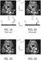
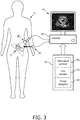
- FIGS. 1A and 1B illustrate a small Y movement of a needle 30 toward an acoustic image plane 11.
- This small Y movement may lead to a Y misalignment of needle 30 and acoustic image plane 11 as demonstrated by the white graphical icon identically shown in an ultrasound image 10.
- needles are often poorly visualized under ultrasound, because they are specular reflectors that reflect the sound away from the imaging probe with a degree of reflection depending upon the insertion angle of the needle with in the imaging plane. Nonetheless, there is value in displaying the needle tip and expected trajectory when the needle is in plane and invisible or out of plane.
- a document US 2011/0245659 A1 discloses a system which facilitates the placement of an instrument internal to an object aided by an overlay superimposed on an image.
- the placement of a needle tip within a patient's body using an overlay superimposed on a sonographic image is facilitated.
- a superimposed overlay of embodiments is created by monitoring a fixed point of an external portion of the instrument in relation to an imaging transducer.
- a document US 2013/0041252 A1 discloses an ultrasound receive beamformer configured for one-way only beamforming of transmissive ultrasound using one-way delays.
- the receive beamforming in some embodiments is used to track, in real time, a catheter, needle or other surgical tool within an image of a region of interest.
- the tool can have embedded at its tip a small ultrasound transmitter or receiver for transmitting or receiving the transmissive ultrasound.
- a document US 2013/0211243 A1 discloses an ultrasound imaging system that has a 3D location system and a data store for recording locations within a patient. Navigation to target locations is facilitated by providing graphical elements superposed on a 2-dimensional image.
- a document US 2010/0298704 A1 discloses an ultrasound system having an ultrasound transducer equipped with a position marker and a needle equipped with a position marker.
- the position markers allow the position and orientation of the transducer and needle to be determined.
- the present invention adheres to the operating principle of acoustic imaging by facilitating a tracking and visualization of the interventional tool via an overlay of a graphical icon (e.g., a marker) indicating the interventional tool on the ultrasound image.
- a graphical icon e.g., a marker
- One or more features/aspects of the graphical icon is modulated as a function of a distance of the interventional tool (e.g., the tip of the interventional tool) to the ultrasound imaging plane.
- a size of a graphical icon illustrated as a white X marker overlain on ultrasound image 10 increases as interventional tool is moved in a Y direction of acoustic image plane 11 as shown in FIGS. 1A and 1B . This will significantly help a physician align the interventional tool with the imaging probe, which results in good confidence, fast procedures and good outcomes, particularly even when the interventional tool is invisible to conventional imaging (i.e., out of plane).
- One form of the present invention is tool navigation system employing an ultrasound probe, an ultrasound scanner, an interventional tool (e.g., a needle or a catheter), a plurality of ultrasound transducers, a tool tracker and an image navigator.
- the ultrasound probe generates an acoustic image plane for scanning an anatomical region
- the ultrasound scanner generates an ultrasound image of the anatomical region from a scan of the anatomical region.
- the interventional tool is navigated within the anatomical region relative to the acoustic image plane, and the ultrasound transducers facilitate a tracking by the tool tracker of a distance of the interventional tool relative to the acoustic image plane.
- the image navigator displays a graphical icon within the ultrasound image of the anatomical region as generated by the ultrasound scanner for illustrating a tracking of the interventional tool relative to the acoustic image plane by the tool tracker.
- One or more aspects of the graphical icon are modulated by the image navigator responsive to a distance of the interventional tool relative to the acoustic image plane as the interventional tool is navigated within the anatomical region.
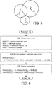
- FIG. 3 exemplary embodiments of the present invention will be provided herein directed to a tool navigation system shown in FIG. 3 .
- the tool navigation system employs an ultrasound probe 20, an interventional tool 30, an ultrasound scanner 60, a tool tracker 70, and an image navigator 80.
- Ultrasound probe 20 is any device as known in the art for scanning an anatomical region of a patient via acoustic energy to visualize subcutaneous body structures (e.g., tendons, muscles, joints, vessels and internal organ, etc.), such as, for example, a scanning an anatomical region 12 of a patient 11 as shown in FIG. 3 .
- subcutaneous body structures e.g., tendons, muscles, joints, vessels and internal organ, etc.
- Examples of ultrasound probe 20 include, but are not limited to, a two-dimensional (“2D”) ultrasound probe having a one-dimensional (“1D”) transducer array, linear or curved.
- Ultrasound scanner 60 is a structural configuration of hardware, software, firmware and/or circuitry as known in the art for generating an ultrasound image of the anatomical region of the patient as scanned by ultrasound probe 20 (e.g., an ultrasound image 10 of a fetus as shown in FIGS. 1-3 ).
- Interventional tool 30 is any tool as known in the art for performing interventional procedures involving a navigation of interventional tool 30 within the anatomical region.
- Examples of interventional tool 30 include, but are not limited to, a needle and a catheter, and examples of interventional procedures include, but are not limited to, biopsies, fluid drainage, nerve blocks, vascular access, etc.
- interventional tool 30 may be equipped with one or more ultrasound transducers in the form of transmitters, receivers and/or transceivers as known in the art. More particularly, one ultrasound transducer provides information in a position of a designated area of interventional tool 30 (e.g., a distal tip of interventional tool 30), and two or more ultrasound transducers provide orientation information that facilitates a displaying of a projected path of interventional tool 30 and a projected intersection point with the ultrasound imaging plane 11, thus further facilitating out-of-plane approaches (which are otherwise blind).
- one ultrasound transducer provides information in a position of a designated area of interventional tool 30 (e.g., a distal tip of interventional tool 30)
- two or more ultrasound transducers provide orientation information that facilitates a displaying of a projected path of interventional tool 30 and a projected intersection point with the ultrasound imaging plane 11, thus further facilitating out-of-plane approaches (which are otherwise blind).
- a pair of ultrasound transducers 31 are embedded in a known configuration adjacent a distal tip on interventional tool 30.
- ultrasound transducers 31 may either be separated by non-overlapping frequency ranges, and/or be fired one after the other to facilitate an individual tracking of ultrasound transducers 31.
- signals for each ultrasound transducer 31 needs to be individualized (e.g., with non-overlapping bandwidths, a switch, two (2) independent cables, or signal processing methods for signal separation).
- ultrasound probe 20 may be equipped with one or more ultrasound transducers 21 for tracking ultrasound transducers 31. More particularly, three (3) or more ultrasound transducers 21 yield satisfactory position estimates of ultrasound transducers 31.
- ultrasound transducers 21 are disposed on ultrasound probe 20 in a manner providing a wide acceptance angle in order to efficiently track ultrasound transducers 31 within a wide field of view.
- ultrasound transducers 21 are disposed on a 2D surface around the array perimeter of ultrasound probe 20.
- ultrasound transducers 21 may be mounted on ultrasound probe 20 as a clip-on device or embedded in a design of ultrasound probe 20. In either case, a simple calibration between the tracked position and the image may be needed. Such a calibration may involve a clicking on tip of interventional tool 30 on a pulse-echo image under a controlled imaging environment.
- Tool tracker 70 is a structural configuration of hardware, software, firmware and/or circuitry as known in the art for executing technique(s) for tracking a position of interventional tool 30 relative to the ultrasound image of the anatomical region.
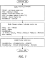
- tool tracker 70 executes a trilateration algorithm for determining a 3D position of ultrasound transducers 31 based on a time of flight of signals between ultrasound transducers 21 and ultrasound transducers 31.
- tool tracker 70 executes an algorithm for computing sensor position with respect to the imaging frame of reference. More particularly, tool tracker 70 determines a projection of a 3D position (X-azimuth, Z-depth, Y-elevation) onto a 2D position in the imaging plane 12 (x-z or r-theta). For this embodiment, a Z-depth (or range) coordinate is obtained by measuring a time of flight of ultrasound signals from ultrasound probe 20 to ultrasound transducers 31, and an X-azimuth (or angular) position is obtained by searching for a maximum received amplitude across received beams at ultrasound transducers 31.
- a Z-depth (or range) coordinate is obtained by measuring a time of flight of ultrasound signals from ultrasound probe 20 to ultrasound transducers 31, and an X-azimuth (or angular) position is obtained by searching for a maximum received amplitude across received beams at ultrasound transducers 31.
- a qualitative estimate of the Y coordinate is obtained by recording the received amplitude of the signals at transducers 31 and comparing it to a past history: increasing amplitude generally means that the sensors 31 are approaching imaging plane 11, whereas a decreasing amplitude means that the sensors 31 are going further away from imaging plane 11.
- Image navigator 80 is a structural configuration of hardware, software, firmware and/or circuitry as known in the art for executing technique(s) for displaying an ultrasound image as generated by ultrasound scanner 60 and in accordance with the present invention for generating a graphical icon for illustrating a tracking of interventional tool 30 relative to the acoustic image plane 11 by tool tracker 70. More particularly, as interventional tool 30 is navigated within the anatomical region, image navigator 80 modulates one or more aspects of the graphical icon (e.g., size, color, shape) to qualitatively indicate a tracked distance of the interventional tool 30 relative to the acoustic image plane 11.
- the graphical icon e.g., size, color, shape
- image navigator 80 inputs data 61 from ultrasound scanner 60 representative of ultrasound image 10 and inputs data 71 from tool tracker 70 representative of a 3D position (X-azimuth, Z-depth) of interventional tool 30 relative to acoustic image plane 11.
- exemplary embodiments of image navigator 80 will be provided herein directed to a size modulation of a marker as shown in FIGS. 6-8 to qualitatively indicate a distance of the ultrasound transducers 31 to ultrasound image plane 11. While these exemplary embodiments uses the amplitudes or signal-to-noise ratios SNRs of received signals and compares them to a history of received amplitudes or SNRs to modulate the marker appearance, those having ordinary skill in the art will appreciate how to apply the principles of these exemplary embodiments to other modulated aspects (e.g., shape, color, bar graph, etc.) and signals quantifying of the Y-elevation distance. Those having ordinary skill in the art will also appreciate various modifications and variations of these exemplary embodiments of graphical icon modulation.
- the size of the marker (the variable 'markerSize') is maximum (to a fixed maximum size 'maxSize') when the signal level (V) at ultrasound transducer 31 drops below a certain voltage or a certain SNR, and minimum (to a fixed minimum size 'minSize') when an ultrasound transducer 31 is on imaging plane 11 at any depth.
- the size of the marker is intermediate.
- the size of the marker may be the size of the marker (the variable 'markerSize') is maximum (to a fixed maximum size 'maxSize') when an ultrasound transducer 31 is on imaging plane 11 at any depth, and minimum (to a fixed minimum size 'minSize') when the signal level (V) at ultrasound transducer 31 drops below a certain voltage or a certain SNR.
- minV or minSNR minimum acceptable signal level
- the minimum marker size corresponds to the minimum acceptable received voltage or received SNR, which is a fixed parameter ('minV'/'minSNR'). At lower received signal levels, the marker is no longer displayed. This eliminates the possibility to display potentially wrong sensor locations in low-SNR scenarios.
- a monotonically increasing curve of size versus received signal amplitude or SNR is implemented.
- the marker size "markerSize” is thus directly representing the received signal strength, which increases at a given depth as ultrasound transducer 31 approaches the imaging plane 11 and decreases as it goes away from the imaging plane 11.
- FIG. 6 illustrates a flowchart 90 representative of an exemplary fixed max voltage embodiment.
- Image navigator 80 returns to stage S92 to repeat stages S92 and S93 as needed.
- the maximum marker size ('maxSize') is variable and corresponds to the maximum signal strength received by ultrasound transducer 31 since the experiment was started (variable 'maxV'). Each time a signal is received, its strength is compared to the maximum past received signal. If it exceeds it, the signal 'maxV' corresponding to the maximum marker size is updated. This embodiment ensures a maximum marker size excursion as interventional tool 30 is advanced within the anatomical region.
- FIG. 7 illustrates a flowchart 100 representative of an exemplary variable max voltage embodiment.
- a stage S101 of flowchart 100 encompasses image navigator 80 acquiring parameters necessary for a calculation by image navigator 80 of 'markerSize C ' during a stage S102 of flowchart 100 as a function of the measured voltage V indicative of the received signal amplitude compared to variable 'maxV V '.
- stage S101 involves setting 'maxV' to 0 and markerSize to a 'defaultSize'
- Image navigator 80 returns to stage S102 to repeat stages S102 and S103 as needed.
- the fixed max voltage and the variable max voltage embodiments ensure displaying a growing marker as ultrasound transducer 31 is moved toward the imaging plane 11 at a given imaging depth.
- the received signal amplitude also depends on depth so that the variation of marker size as a function of out-of-plane distance is depth-dependent, and changes in sensor depth also will result in changes in marker size.
- the current received signal amplitude is compared to a short history of signal amplitudes.
- the history length is a set parameter typically set to a few seconds of data, or a characteristic time for sensor advancement into the ultrasound field.
- the maximum marker size (a set parameter) is set to correspond to the maximum received signal or SNR during this history.
- the history file is updated each time ultrasound transducer 31 is measured to move significantly (over a set distance threshold) as measured by its tracked position. This guarantees that the maximum set marker size will be displayed when ultrasound transducer 31 is in plane at any depth, provided that the characteristic time of cross-plane motion is faster than that of depth motion.
- FIG. 8 illustrates a flowchart 110 representative of the minimal movement embodiment.
- a stage Sill of flowchart 110 encompasses image navigator 80 acquiring parameters necessary for a calculation by image navigator 80 of 'markerSizec' during a stage S113 of flowchart 110 as a function of a history of measured voltage V indicative of the received signal amplitude as related to movement of interventional tool 30.
- an initial implementation of stage Sill involves setting 'maxV' to 0; markerSize to a 'defaultSize', and a history to zeros.
- Image navigator 80 returns to stage S112 to repeat stages S112- S114 as needed.
- All the above embodiments may advantageously modified by taking into account the measured current spatial position, especially the depth, of interventional tool 30.
- a field amplitude varies with depth and out-of-plane distance (and to a lesser extent with azimuth). The goal is to eliminate the variation in displayed marker size as a function of depth, but keep the variations on marker size as a function of out-of-plane distance at a given depth.
- a look-up table of marker sizes as a function of depth is established. This table is built based on some calibration of the spatial field which is achieved beforehand by simulation or/and measurement or on-the-fly by simulation. Different look-up tables may be used for different probes, imaging modes, settings ( e.g. beam density) and transmit focal depth, for varying degrees of accuracy.
- the bulk attenuation within the anatomical region may be measured by fitting an exponential to the curve giving backscattered data amplitude as a function of depth (on the pulse-echo data), and added as an input to the simulation.
- the maximum marker size may be a function of interventional tool 30.
- the current read voltage is compared only to those voltage readings in the history with a similar depth (e.g., no further than 1cm away from the current reading).
- a coarse spatial grid may be established and for each pixel in that grid, the maximum read value in the corresponding area is set as the local maximum read value maxV.
- a tool tracker (70) comprises hardware, software, firmware and/or circuitry for executing a tracking technique to track a position of an interventional tool (30) comprising at least one ultrasound transducer (31) disposed on a distal tip of the interventional tool (30) with an ultrasound probe (20), relative to an acoustic image plane (11) corresponding to an ultrasound image of an anatomical region generated by the ultrasound probe (20), based on a time of flight and an amplitude of ultrasound signals corresponding to each of a plurality of beams communicated from the ultrasound probe (20) to the at least one ultrasound transducer (31), wherein the tool tracker (70) is configured to execute an algorithm that determines a projection of a 3D position of the at least one ultrasound transducer (31) including an X-azimuth, a Z-depth and a Y-elevation of the ultrasound transducer (31) relative to the ultrasound probe (20), onto a 2D position in the acoustic image plane (11) by performing the method steps of:
Claims (1)
- Werkzeugverfolger (70), umfassend Hardware, Software, Firmware und/oder Schaltungen zum Ausführen einer Verfolgungstechnik zum Verfolgen einer Position eines Interventionswerkzeugs (30), das mindestens einen Ultraschallwandler (31) umfasst, der an einer distalen Spitze des Interventionswerkzeugs (30) angeordnet ist, mit einer Ultraschallsonde (20) relativ zu einer akustischen Bildebene (11), die einem Ultraschallbild eines von der Ultraschallsonde (20) erzeugten anatomischen Bereichs entspricht, basierend auf einer Flugzeit und einer Amplitude von Ultraschallsignalen entsprechend jedem von mehreren Strahlen, die von der Ultraschallsonde (20) zu dem mindestens einen Ultraschallwandler (31) übertragen werden,
wobei der Werkzeugverfolger (70) konfiguriert ist, um einen Algorithmus auszuführen, der eine Projektion einer 3D-Position des mindestens einen Ultraschallwandlers (31) bestimmt, einschließlich eines X-Azimut, einer Z-Tiefe und einer Y-Höhe des mindestens einen enthält einen Ultraschallwandler (31) auf eine 2D-Position in der akustischen Bildebene (11) durch Ausführen der Verfahrensschritte von:Bestimmen der Z-Tiefenkoordinate durch Messen der Flugzeit der Ultraschallsignale von der Ultraschallsonde (20) zu dem mindestens einen Ultraschallwandler (31);Bestimmen der X-Azimutposition durch Suchen nach einer maximalen empfangenen Amplitude über Strahlen von der Ultraschallsonde (20), die an dem mindestens einen Ultraschallwandler (31) empfangen wurde;Schätzen der Y-Höhe, die den Abstand des mindestens einen Ultraschallwandlers (31) relativ zur akustischen Bildebene (11) umfasst, durch Aufzeichnen der empfangenen Amplitude der Ultraschallsignale am mindestens einen Ultraschallwandler (31) und Vergleichen mit einem Vorgeschichte der Ultraschallsignale in der Vergangenheit, wobei eine zunehmende Amplitude bedeutet, dass sich der mindestens eine Ultraschallwandler (31) der akustischen Bildebene (11) nähert, und eine abnehmende Amplitude bedeutet, dass der mindestens eine Ultraschallwandler (31) weiter entfernt ist von der akustischen Bildebene (11).
Priority Applications (1)
| Application Number | Priority Date | Filing Date | Title |
|---|---|---|---|
| EP20188904.5A EP3760129A1 (de) | 2014-01-02 | 2015-01-02 | Instrumentenausrichtung und -verfolgung mit ultraschallbildgebungsebene |
Applications Claiming Priority (3)
| Application Number | Priority Date | Filing Date | Title |
|---|---|---|---|
| US201461922882P | 2014-01-02 | 2014-01-02 | |
| EP15704590.7A EP3089671B1 (de) | 2014-01-02 | 2015-01-02 | Instrumentenausrichtung und -verfolgung mit ultraschallbildgebungsebene |
| PCT/IB2015/050023 WO2015101949A1 (en) | 2014-01-02 | 2015-01-02 | Instrument alignment and tracking with ultrasound imaging plane |
Related Parent Applications (2)
| Application Number | Title | Priority Date | Filing Date |
|---|---|---|---|
| EP15704590.7A Division EP3089671B1 (de) | 2014-01-02 | 2015-01-02 | Instrumentenausrichtung und -verfolgung mit ultraschallbildgebungsebene |
| EP15704590.7A Division-Into EP3089671B1 (de) | 2014-01-02 | 2015-01-02 | Instrumentenausrichtung und -verfolgung mit ultraschallbildgebungsebene |
Related Child Applications (2)
| Application Number | Title | Priority Date | Filing Date |
|---|---|---|---|
| EP20188904.5A Division-Into EP3760129A1 (de) | 2014-01-02 | 2015-01-02 | Instrumentenausrichtung und -verfolgung mit ultraschallbildgebungsebene |
| EP20188904.5A Division EP3760129A1 (de) | 2014-01-02 | 2015-01-02 | Instrumentenausrichtung und -verfolgung mit ultraschallbildgebungsebene |
Publications (2)
| Publication Number | Publication Date |
|---|---|
| EP3508134A1 EP3508134A1 (de) | 2019-07-10 |
| EP3508134B1 true EP3508134B1 (de) | 2020-11-04 |
Family
ID=52472359
Family Applications (3)
| Application Number | Title | Priority Date | Filing Date |
|---|---|---|---|
| EP15704590.7A Active EP3089671B1 (de) | 2014-01-02 | 2015-01-02 | Instrumentenausrichtung und -verfolgung mit ultraschallbildgebungsebene |
| EP19153574.9A Active EP3508134B1 (de) | 2014-01-02 | 2015-01-02 | Instrumentenausrichtung und -verfolgung mit ultraschallbildgebungsebene |
| EP20188904.5A Pending EP3760129A1 (de) | 2014-01-02 | 2015-01-02 | Instrumentenausrichtung und -verfolgung mit ultraschallbildgebungsebene |
Family Applications Before (1)
| Application Number | Title | Priority Date | Filing Date |
|---|---|---|---|
| EP15704590.7A Active EP3089671B1 (de) | 2014-01-02 | 2015-01-02 | Instrumentenausrichtung und -verfolgung mit ultraschallbildgebungsebene |
Family Applications After (1)
| Application Number | Title | Priority Date | Filing Date |
|---|---|---|---|
| EP20188904.5A Pending EP3760129A1 (de) | 2014-01-02 | 2015-01-02 | Instrumentenausrichtung und -verfolgung mit ultraschallbildgebungsebene |
Country Status (6)
| Country | Link |
|---|---|
| US (2) | US11096656B2 (de) |
| EP (3) | EP3089671B1 (de) |
| JP (3) | JP6517817B2 (de) |
| CN (2) | CN105873521B (de) |
| RU (1) | RU2689176C2 (de) |
| WO (1) | WO2015101949A1 (de) |
Families Citing this family (40)
| Publication number | Priority date | Publication date | Assignee | Title |
|---|---|---|---|---|
| FR3017042B1 (fr) * | 2014-02-03 | 2017-10-13 | Spineguard | Systeme medical, et procede pour visualiser un point d'entree d'un instrument chirurgical, dans une structure anatomique, et ensemble comprenant un tel systeme medical et un instrument chirurgical |
| US10674997B2 (en) * | 2015-08-10 | 2020-06-09 | Shaohua Hu | Ultrasonic tracking probe and the method |
| US11275150B2 (en) * | 2015-12-16 | 2022-03-15 | Koninklijke Philips N.V. | Interventional device recognition |
| US11413011B2 (en) | 2015-12-22 | 2022-08-16 | Koninklijke Philips N.V. | Ultrasound based tracking |
| WO2017118750A1 (en) * | 2016-01-07 | 2017-07-13 | Universität Bern | Method and system for pose controlled ablation |
| EP3515317B1 (de) * | 2016-09-20 | 2020-05-20 | Koninklijke Philips N.V. | Ultraschallwandlerkachelregistrierung |
| JP7084383B2 (ja) * | 2016-09-30 | 2022-06-14 | コーニンクレッカ フィリップス エヌ ヴェ | 介入装置の機能の追跡 |
| CN114795081A (zh) * | 2016-11-11 | 2022-07-29 | 波士顿科学医学有限公司 | 引导系统和相关联的方法 |
| CN110312476A (zh) * | 2017-01-19 | 2019-10-08 | 皇家飞利浦有限公司 | 用于对介入设备进行成像和跟踪的系统和方法 |
| EP3582693B1 (de) * | 2017-02-14 | 2021-04-07 | Koninklijke Philips N.V. | Fokusverfolgung in ultraschallsystem zur vorrichtungsverfolgung |
| US11766234B2 (en) * | 2017-06-06 | 2023-09-26 | Avent, Inc. | System and method for identifying and navigating anatomical objects using deep learning networks |
| EP3648674A1 (de) * | 2017-07-07 | 2020-05-13 | Koninklijke Philips N.V. | Robotische instrumentenführungsintegration mit einer akustischen sonde |
| US20200253668A1 (en) * | 2017-08-28 | 2020-08-13 | Koninklijke Philips N.V. | Automatic field of view updating of position tracked interventional device |
| DE102018200688B4 (de) * | 2018-01-17 | 2023-05-17 | Robert Bosch Gmbh | Verfahren und Vorrichtung zum Betreiben eines akustischen Sensors |
| EP3755229A1 (de) * | 2018-02-22 | 2020-12-30 | Koninklijke Philips N.V. | Verfolgung einer interventionellen medizinischen vorrichtung |
| US20190262082A1 (en) * | 2018-02-26 | 2019-08-29 | Covidien Lp | System and method for performing a percutaneous navigation procedure |
| US20210000553A1 (en) * | 2018-05-04 | 2021-01-07 | Hologic, Inc. | Introducer and localization wire visualization |
| EP3632333A1 (de) * | 2018-10-05 | 2020-04-08 | Koninklijke Philips N.V. | Positionierung einer interventionellen vorrichtung in bezug auf eine ultraschallbildebene |
| EP3632331A1 (de) * | 2018-10-05 | 2020-04-08 | Koninklijke Philips N.V. | Interventionelle vorrichtungspositionierung unter verwendung von ultraschallsignalen |
| EP3632332A1 (de) | 2018-10-05 | 2020-04-08 | Koninklijke Philips N.V. | Verfolgung einer interventionsvorrichtung in bezug auf eine ultraschallbildebene |
| WO2020030665A1 (en) | 2018-08-08 | 2020-02-13 | Koninklijke Philips N.V. | Interventional device positioning respective an ultrasound image plane |
| WO2020030557A1 (en) | 2018-08-08 | 2020-02-13 | Koninklijke Philips N.V. | Tracking an interventional device respective an ultrasound image plane |
| WO2020030746A1 (en) | 2018-08-08 | 2020-02-13 | Koninklijke Philips N.V. | Interventional device positioning using ultrasound signals |
| CN109044531B (zh) * | 2018-08-20 | 2024-02-06 | 真健康(北京)医疗科技有限公司 | 一种接触感应式的末端位置导航跟踪装置 |
| CN112601495A (zh) * | 2018-08-22 | 2021-04-02 | 皇家飞利浦有限公司 | 用于约束介入声学成像中的传感器跟踪估计的系统、设备和方法 |
| US20200069285A1 (en) * | 2018-08-31 | 2020-03-05 | General Electric Company | System and method for ultrasound navigation |
| CN109171817B (zh) * | 2018-09-05 | 2021-12-07 | 浙江深博医疗技术有限公司 | 三维乳腺超声扫描方法及超声扫描系统 |
| US11642100B2 (en) * | 2018-09-20 | 2023-05-09 | Mayo Foundation For Medical Education And Research | Systems and methods for localizing a medical device using symmetric Doppler frequency shifts measured with ultrasound imaging |
| JP6469295B1 (ja) * | 2018-09-21 | 2019-02-13 | 株式会社A−Traction | 手術支援装置、その制御方法、並びに手術支援システム |
| US11730443B2 (en) * | 2019-06-13 | 2023-08-22 | Fujifilm Sonosite, Inc. | On-screen markers for out-of-plane needle guidance |
| EP3804629A1 (de) * | 2019-10-10 | 2021-04-14 | Koninklijke Philips N.V. | Ultraschallobjektpunktverfolgung |
| WO2021013971A1 (en) * | 2019-07-24 | 2021-01-28 | Koninklijke Philips N.V. | Ultrasound object point tracking |
| EP3808280A1 (de) | 2019-10-14 | 2021-04-21 | Koninklijke Philips N.V. | Ultraschallbasierte vorrichtungslokalisierung |
| JP7345631B2 (ja) | 2019-08-15 | 2023-09-15 | コーニンクレッカ フィリップス エヌ ヴェ | 超音波ベースの装置位置特定 |
| CN110477842B (zh) * | 2019-08-26 | 2020-07-24 | 清华大学 | 体内检测系统和方法 |
| CN111436937A (zh) * | 2020-03-16 | 2020-07-24 | 北京东软医疗设备有限公司 | 导管/导丝跟踪方法、装置及扫描设备 |
| JP2023554634A (ja) | 2020-12-17 | 2023-12-28 | コーニンクレッカ フィリップス エヌ ヴェ | 位置情報を求めるためのシステム及び方法 |
| EP4026499A1 (de) * | 2021-01-12 | 2022-07-13 | Koninklijke Philips N.V. | System und verfahren zur bestimmung von positionsinformationen |
| DE102021201515A1 (de) | 2021-02-17 | 2022-08-18 | B. Braun Melsungen Aktiengesellschaft | Medizinisches Instrument und medizinisches Ultraschallsystem mit einem solchen Instrument |
| CN113693689A (zh) * | 2021-08-27 | 2021-11-26 | 电子科技大学 | 一种超声引导穿刺的方法和装置 |
Family Cites Families (27)
| Publication number | Priority date | Publication date | Assignee | Title |
|---|---|---|---|---|
| US4249539A (en) * | 1979-02-09 | 1981-02-10 | Technicare Corporation | Ultrasound needle tip localization system |
| US5158088A (en) | 1990-11-14 | 1992-10-27 | Advanced Technology Laboratories, Inc. | Ultrasonic diagnostic systems for imaging medical instruments within the body |
| EP0845959A4 (de) * | 1995-07-16 | 1998-09-30 | Ultra Guide Ltd | Hand-freies ziehlen einer nadelführung |
| JPH09271472A (ja) * | 1996-04-04 | 1997-10-21 | Ge Yokogawa Medical Syst Ltd | 穿刺針の位置検出装置および超音波診断装置 |
| JP4443672B2 (ja) | 1998-10-14 | 2010-03-31 | 株式会社東芝 | 超音波診断装置 |
| EP1623674B1 (de) * | 2003-05-08 | 2016-04-13 | Hitachi Medical Corporation | Referenzbild-darstellungsverfahren für ultrasonographie und ultraschallgerät |
| RU2256169C1 (ru) | 2004-02-13 | 2005-07-10 | Общестов с ограниченной ответственностью "Институт рентгеновской оптики" | Способ и устройство для исследования объекта в рассеянном и/или прошедшем излучении |
| US20090118612A1 (en) * | 2005-05-06 | 2009-05-07 | Sorin Grunwald | Apparatus and Method for Vascular Access |
| EP2289454B1 (de) * | 2005-06-06 | 2020-03-25 | Intuitive Surgical Operations, Inc. | Laparoskopisches Ultraschall-Robotersystem für chirurgische Zwecke |
| BRPI0807295A2 (pt) * | 2007-03-03 | 2014-05-06 | Activiews Ltd | Método para planejar um procedimento com agulha, sistema para planejar um procedimento com agulha e meio legível em computador. |
| JP2009066074A (ja) * | 2007-09-11 | 2009-04-02 | Olympus Medical Systems Corp | 超音波診断装置 |
| JP5121384B2 (ja) * | 2007-10-12 | 2013-01-16 | 株式会社東芝 | 超音波診断装置 |
| JP5199690B2 (ja) * | 2008-02-07 | 2013-05-15 | 株式会社日立メディコ | 超音波診断装置 |
| US8556815B2 (en) * | 2009-05-20 | 2013-10-15 | Laurent Pelissier | Freehand ultrasound imaging systems and methods for guiding fine elongate instruments |
| US20110245659A1 (en) | 2010-04-01 | 2011-10-06 | Sonosite, Inc. | Systems and methods to assist with internal positioning of instruments |
| EP2566394B1 (de) * | 2010-05-03 | 2016-12-14 | Koninklijke Philips N.V. | Ultraschallverfolgung von ultraschallwandlern bei einem interventionellen instrument |
| US20120179038A1 (en) * | 2011-01-07 | 2012-07-12 | General Electric Company | Ultrasound based freehand invasive device positioning system and method |
| JP2012217632A (ja) * | 2011-04-08 | 2012-11-12 | Hitachi Medical Corp | 画像診断装置及び画像処理装置 |
| EP2717772B1 (de) * | 2011-06-13 | 2021-05-26 | Koninklijke Philips N.V. | Dreidimensionale nadellokalisation mit einer zweidimensionalen bildgebungssonde |
| CN103620476A (zh) * | 2011-06-30 | 2014-03-05 | 通用电气医疗集团生物科学公司 | 生物成像的图像质量优化 |
| PL2997901T3 (pl) * | 2011-09-06 | 2018-08-31 | Ezono Ag | Sonda do obrazowania |
| US9295449B2 (en) | 2012-01-23 | 2016-03-29 | Ultrasonix Medical Corporation | Landmarks for ultrasound imaging |
| JP6039903B2 (ja) * | 2012-01-27 | 2016-12-07 | キヤノン株式会社 | 画像処理装置、及びその作動方法 |
| WO2014143258A1 (en) * | 2013-03-11 | 2014-09-18 | Untited Technologies Corporation | Phased array billet data evaluation software |
| AU2014231327C1 (en) * | 2013-03-15 | 2019-08-01 | Conavi Medical Inc. | Active localization and visualization of minimally invasive devices using ultrasound |
| GB201307551D0 (en) * | 2013-04-26 | 2013-06-12 | Ucl Business Plc | A method and apparatus for determining the location of a medical instrument with respect to ultrasound imaging and a medical instrument |
| KR101533591B1 (ko) * | 2013-07-08 | 2015-07-06 | 삼성메디슨 주식회사 | 의료 영상 장치 및 의료 영상 제공 방법 |
-
2015
- 2015-01-02 JP JP2016543075A patent/JP6517817B2/ja active Active
- 2015-01-02 EP EP15704590.7A patent/EP3089671B1/de active Active
- 2015-01-02 EP EP19153574.9A patent/EP3508134B1/de active Active
- 2015-01-02 CN CN201580003519.8A patent/CN105873521B/zh active Active
- 2015-01-02 WO PCT/IB2015/050023 patent/WO2015101949A1/en active Application Filing
- 2015-01-02 RU RU2016131480A patent/RU2689176C2/ru active
- 2015-01-02 CN CN202010915911.2A patent/CN111973225A/zh active Pending
- 2015-01-02 US US15/109,015 patent/US11096656B2/en active Active
- 2015-01-02 EP EP20188904.5A patent/EP3760129A1/de active Pending
-
2019
- 2019-04-18 JP JP2019079176A patent/JP7098565B2/ja active Active
-
2020
- 2020-12-21 JP JP2020210984A patent/JP7165181B2/ja active Active
-
2021
- 2021-07-27 US US17/385,998 patent/US11872076B2/en active Active
Non-Patent Citations (1)
| Title |
|---|
| None * |
Also Published As
| Publication number | Publication date |
|---|---|
| EP3089671B1 (de) | 2019-05-22 |
| JP7098565B2 (ja) | 2022-07-11 |
| JP6517817B2 (ja) | 2019-05-22 |
| RU2689176C2 (ru) | 2019-05-24 |
| WO2015101949A1 (en) | 2015-07-09 |
| RU2016131480A (ru) | 2018-02-07 |
| JP7165181B2 (ja) | 2022-11-02 |
| RU2016131480A3 (de) | 2018-08-03 |
| US20160324501A1 (en) | 2016-11-10 |
| US11872076B2 (en) | 2024-01-16 |
| US11096656B2 (en) | 2021-08-24 |
| CN105873521B (zh) | 2020-09-15 |
| EP3089671A1 (de) | 2016-11-09 |
| EP3508134A1 (de) | 2019-07-10 |
| CN105873521A (zh) | 2016-08-17 |
| US20210353250A1 (en) | 2021-11-18 |
| JP2021062222A (ja) | 2021-04-22 |
| EP3760129A1 (de) | 2021-01-06 |
| CN111973225A (zh) | 2020-11-24 |
| JP2019134958A (ja) | 2019-08-15 |
| JP2017500955A (ja) | 2017-01-12 |
Similar Documents
| Publication | Publication Date | Title |
|---|---|---|
| US11872076B2 (en) | Instrument alignment and tracking with ultrasound imaging plane | |
| US11331076B2 (en) | Method and system for displaying ultrasonic elastic measurement | |
| US11006926B2 (en) | Region of interest placement for quantitative ultrasound imaging | |
| US20220273258A1 (en) | Path tracking in ultrasound system for device tracking | |
| WO2014003070A1 (ja) | 超音波診断装置及び超音波画像処理方法 | |
| CN105899143A (zh) | 超声导航/组织定征组合 | |
| JP2008086742A (ja) | 超音波プローブの軌跡表現装置及び超音波診断装置 | |
| CN104684488B (zh) | 用于超声狭窄评估的自动双平面‑pw工作流程 | |
| EP2921116B1 (de) | Medizinische bildanzeigevorrichtung, verfahren und programm | |
| US20090082668A1 (en) | Ultrasonic imaging apparatus and method for generating ultrasonic image | |
| JP2012143557A (ja) | 超音波方式のフリーハンド侵襲的デバイス位置決めシステム及び方法 | |
| US10952705B2 (en) | Method and system for creating and utilizing a patient-specific organ model from ultrasound image data | |
| US10213185B2 (en) | Ultrasonic diagnostic apparatus | |
| US20210015448A1 (en) | Methods and systems for imaging a needle from ultrasound imaging data | |
| US20140024940A1 (en) | Ultrasonic diagnostic apparatus and sensor selection apparatus | |
| US20200037984A1 (en) | Focus tracking in ultrasound system for device tracking | |
| US20200405264A1 (en) | Region of interest positioning for longitudinal montioring in quantitative ultrasound | |
| EP3632331A1 (de) | Interventionelle vorrichtungspositionierung unter verwendung von ultraschallsignalen | |
| US20110098567A1 (en) | Three dimensional pulsed wave spectrum ultrasonic diagnostic apparatus and three dimensional pulsed wave spectrum data generation method |
Legal Events
| Date | Code | Title | Description |
|---|---|---|---|
| PUAI | Public reference made under article 153(3) epc to a published international application that has entered the european phase |
Free format text: ORIGINAL CODE: 0009012 |
|
| STAA | Information on the status of an ep patent application or granted ep patent |
Free format text: STATUS: THE APPLICATION HAS BEEN PUBLISHED |
|
| AC | Divisional application: reference to earlier application |
Ref document number: 3089671 Country of ref document: EP Kind code of ref document: P |
|
| AK | Designated contracting states |
Kind code of ref document: A1 Designated state(s): AL AT BE BG CH CY CZ DE DK EE ES FI FR GB GR HR HU IE IS IT LI LT LU LV MC MK MT NL NO PL PT RO RS SE SI SK SM TR |
|
| STAA | Information on the status of an ep patent application or granted ep patent |
Free format text: STATUS: REQUEST FOR EXAMINATION WAS MADE |
|
| 17P | Request for examination filed |
Effective date: 20200110 |
|
| RBV | Designated contracting states (corrected) |
Designated state(s): AL AT BE BG CH CY CZ DE DK EE ES FI FR GB GR HR HU IE IS IT LI LT LU LV MC MK MT NL NO PL PT RO RS SE SI SK SM TR |
|
| RAP1 | Party data changed (applicant data changed or rights of an application transferred) |
Owner name: KONINKLIJKE PHILIPS N.V. |
|
| GRAP | Despatch of communication of intention to grant a patent |
Free format text: ORIGINAL CODE: EPIDOSNIGR1 |
|
| STAA | Information on the status of an ep patent application or granted ep patent |
Free format text: STATUS: GRANT OF PATENT IS INTENDED |
|
| INTG | Intention to grant announced |
Effective date: 20200526 |
|
| GRAS | Grant fee paid |
Free format text: ORIGINAL CODE: EPIDOSNIGR3 |
|
| GRAA | (expected) grant |
Free format text: ORIGINAL CODE: 0009210 |
|
| STAA | Information on the status of an ep patent application or granted ep patent |
Free format text: STATUS: THE PATENT HAS BEEN GRANTED |
|
| AC | Divisional application: reference to earlier application |
Ref document number: 3089671 Country of ref document: EP Kind code of ref document: P |
|
| AK | Designated contracting states |
Kind code of ref document: B1 Designated state(s): AL AT BE BG CH CY CZ DE DK EE ES FI FR GB GR HR HU IE IS IT LI LT LU LV MC MK MT NL NO PL PT RO RS SE SI SK SM TR |
|
| REG | Reference to a national code |
Ref country code: GB Ref legal event code: FG4D |
|
| REG | Reference to a national code |
Ref country code: CH Ref legal event code: EP |
|
| REG | Reference to a national code |
Ref country code: AT Ref legal event code: REF Ref document number: 1329784 Country of ref document: AT Kind code of ref document: T Effective date: 20201115 |
|
| REG | Reference to a national code |
Ref country code: IE Ref legal event code: FG4D |
|
| REG | Reference to a national code |
Ref country code: DE Ref legal event code: R096 Ref document number: 602015061749 Country of ref document: DE |
|
| REG | Reference to a national code |
Ref country code: NL Ref legal event code: MP Effective date: 20201104 |
|
| REG | Reference to a national code |
Ref country code: AT Ref legal event code: MK05 Ref document number: 1329784 Country of ref document: AT Kind code of ref document: T Effective date: 20201104 |
|
| PG25 | Lapsed in a contracting state [announced via postgrant information from national office to epo] |
Ref country code: FI Free format text: LAPSE BECAUSE OF FAILURE TO SUBMIT A TRANSLATION OF THE DESCRIPTION OR TO PAY THE FEE WITHIN THE PRESCRIBED TIME-LIMIT Effective date: 20201104 Ref country code: RS Free format text: LAPSE BECAUSE OF FAILURE TO SUBMIT A TRANSLATION OF THE DESCRIPTION OR TO PAY THE FEE WITHIN THE PRESCRIBED TIME-LIMIT Effective date: 20201104 Ref country code: PT Free format text: LAPSE BECAUSE OF FAILURE TO SUBMIT A TRANSLATION OF THE DESCRIPTION OR TO PAY THE FEE WITHIN THE PRESCRIBED TIME-LIMIT Effective date: 20210304 Ref country code: GR Free format text: LAPSE BECAUSE OF FAILURE TO SUBMIT A TRANSLATION OF THE DESCRIPTION OR TO PAY THE FEE WITHIN THE PRESCRIBED TIME-LIMIT Effective date: 20210205 Ref country code: NO Free format text: LAPSE BECAUSE OF FAILURE TO SUBMIT A TRANSLATION OF THE DESCRIPTION OR TO PAY THE FEE WITHIN THE PRESCRIBED TIME-LIMIT Effective date: 20210204 |
|
| PG25 | Lapsed in a contracting state [announced via postgrant information from national office to epo] |
Ref country code: BG Free format text: LAPSE BECAUSE OF FAILURE TO SUBMIT A TRANSLATION OF THE DESCRIPTION OR TO PAY THE FEE WITHIN THE PRESCRIBED TIME-LIMIT Effective date: 20210204 Ref country code: SE Free format text: LAPSE BECAUSE OF FAILURE TO SUBMIT A TRANSLATION OF THE DESCRIPTION OR TO PAY THE FEE WITHIN THE PRESCRIBED TIME-LIMIT Effective date: 20201104 Ref country code: LV Free format text: LAPSE BECAUSE OF FAILURE TO SUBMIT A TRANSLATION OF THE DESCRIPTION OR TO PAY THE FEE WITHIN THE PRESCRIBED TIME-LIMIT Effective date: 20201104 Ref country code: IS Free format text: LAPSE BECAUSE OF FAILURE TO SUBMIT A TRANSLATION OF THE DESCRIPTION OR TO PAY THE FEE WITHIN THE PRESCRIBED TIME-LIMIT Effective date: 20210304 Ref country code: PL Free format text: LAPSE BECAUSE OF FAILURE TO SUBMIT A TRANSLATION OF THE DESCRIPTION OR TO PAY THE FEE WITHIN THE PRESCRIBED TIME-LIMIT Effective date: 20201104 Ref country code: ES Free format text: LAPSE BECAUSE OF FAILURE TO SUBMIT A TRANSLATION OF THE DESCRIPTION OR TO PAY THE FEE WITHIN THE PRESCRIBED TIME-LIMIT Effective date: 20201104 Ref country code: AT Free format text: LAPSE BECAUSE OF FAILURE TO SUBMIT A TRANSLATION OF THE DESCRIPTION OR TO PAY THE FEE WITHIN THE PRESCRIBED TIME-LIMIT Effective date: 20201104 |
|
| REG | Reference to a national code |
Ref country code: LT Ref legal event code: MG9D |
|
| PG25 | Lapsed in a contracting state [announced via postgrant information from national office to epo] |
Ref country code: HR Free format text: LAPSE BECAUSE OF FAILURE TO SUBMIT A TRANSLATION OF THE DESCRIPTION OR TO PAY THE FEE WITHIN THE PRESCRIBED TIME-LIMIT Effective date: 20201104 |
|
| PG25 | Lapsed in a contracting state [announced via postgrant information from national office to epo] |
Ref country code: SK Free format text: LAPSE BECAUSE OF FAILURE TO SUBMIT A TRANSLATION OF THE DESCRIPTION OR TO PAY THE FEE WITHIN THE PRESCRIBED TIME-LIMIT Effective date: 20201104 Ref country code: SM Free format text: LAPSE BECAUSE OF FAILURE TO SUBMIT A TRANSLATION OF THE DESCRIPTION OR TO PAY THE FEE WITHIN THE PRESCRIBED TIME-LIMIT Effective date: 20201104 Ref country code: EE Free format text: LAPSE BECAUSE OF FAILURE TO SUBMIT A TRANSLATION OF THE DESCRIPTION OR TO PAY THE FEE WITHIN THE PRESCRIBED TIME-LIMIT Effective date: 20201104 Ref country code: CZ Free format text: LAPSE BECAUSE OF FAILURE TO SUBMIT A TRANSLATION OF THE DESCRIPTION OR TO PAY THE FEE WITHIN THE PRESCRIBED TIME-LIMIT Effective date: 20201104 Ref country code: RO Free format text: LAPSE BECAUSE OF FAILURE TO SUBMIT A TRANSLATION OF THE DESCRIPTION OR TO PAY THE FEE WITHIN THE PRESCRIBED TIME-LIMIT Effective date: 20201104 Ref country code: LT Free format text: LAPSE BECAUSE OF FAILURE TO SUBMIT A TRANSLATION OF THE DESCRIPTION OR TO PAY THE FEE WITHIN THE PRESCRIBED TIME-LIMIT Effective date: 20201104 |
|
| REG | Reference to a national code |
Ref country code: DE Ref legal event code: R097 Ref document number: 602015061749 Country of ref document: DE |
|
| PG25 | Lapsed in a contracting state [announced via postgrant information from national office to epo] |
Ref country code: MC Free format text: LAPSE BECAUSE OF FAILURE TO SUBMIT A TRANSLATION OF THE DESCRIPTION OR TO PAY THE FEE WITHIN THE PRESCRIBED TIME-LIMIT Effective date: 20201104 Ref country code: DK Free format text: LAPSE BECAUSE OF FAILURE TO SUBMIT A TRANSLATION OF THE DESCRIPTION OR TO PAY THE FEE WITHIN THE PRESCRIBED TIME-LIMIT Effective date: 20201104 |
|
| REG | Reference to a national code |
Ref country code: CH Ref legal event code: PL |
|
| PLBE | No opposition filed within time limit |
Free format text: ORIGINAL CODE: 0009261 |
|
| STAA | Information on the status of an ep patent application or granted ep patent |
Free format text: STATUS: NO OPPOSITION FILED WITHIN TIME LIMIT |
|
| PG25 | Lapsed in a contracting state [announced via postgrant information from national office to epo] |
Ref country code: LU Free format text: LAPSE BECAUSE OF NON-PAYMENT OF DUE FEES Effective date: 20210102 |
|
| REG | Reference to a national code |
Ref country code: BE Ref legal event code: MM Effective date: 20210131 |
|
| 26N | No opposition filed |
Effective date: 20210805 |
|
| PG25 | Lapsed in a contracting state [announced via postgrant information from national office to epo] |
Ref country code: AL Free format text: LAPSE BECAUSE OF FAILURE TO SUBMIT A TRANSLATION OF THE DESCRIPTION OR TO PAY THE FEE WITHIN THE PRESCRIBED TIME-LIMIT Effective date: 20201104 Ref country code: NL Free format text: LAPSE BECAUSE OF FAILURE TO SUBMIT A TRANSLATION OF THE DESCRIPTION OR TO PAY THE FEE WITHIN THE PRESCRIBED TIME-LIMIT Effective date: 20201104 Ref country code: IT Free format text: LAPSE BECAUSE OF FAILURE TO SUBMIT A TRANSLATION OF THE DESCRIPTION OR TO PAY THE FEE WITHIN THE PRESCRIBED TIME-LIMIT Effective date: 20201104 |
|
| PG25 | Lapsed in a contracting state [announced via postgrant information from national office to epo] |
Ref country code: SI Free format text: LAPSE BECAUSE OF FAILURE TO SUBMIT A TRANSLATION OF THE DESCRIPTION OR TO PAY THE FEE WITHIN THE PRESCRIBED TIME-LIMIT Effective date: 20201104 Ref country code: CH Free format text: LAPSE BECAUSE OF NON-PAYMENT OF DUE FEES Effective date: 20210131 Ref country code: LI Free format text: LAPSE BECAUSE OF NON-PAYMENT OF DUE FEES Effective date: 20210131 |
|
| PG25 | Lapsed in a contracting state [announced via postgrant information from national office to epo] |
Ref country code: IE Free format text: LAPSE BECAUSE OF NON-PAYMENT OF DUE FEES Effective date: 20210102 |
|
| PG25 | Lapsed in a contracting state [announced via postgrant information from national office to epo] |
Ref country code: IS Free format text: LAPSE BECAUSE OF FAILURE TO SUBMIT A TRANSLATION OF THE DESCRIPTION OR TO PAY THE FEE WITHIN THE PRESCRIBED TIME-LIMIT Effective date: 20210304 |
|
| PG25 | Lapsed in a contracting state [announced via postgrant information from national office to epo] |
Ref country code: BE Free format text: LAPSE BECAUSE OF NON-PAYMENT OF DUE FEES Effective date: 20210131 |
|
| PGFP | Annual fee paid to national office [announced via postgrant information from national office to epo] |
Ref country code: FR Payment date: 20230124 Year of fee payment: 9 |
|
| PG25 | Lapsed in a contracting state [announced via postgrant information from national office to epo] |
Ref country code: CY Free format text: LAPSE BECAUSE OF FAILURE TO SUBMIT A TRANSLATION OF THE DESCRIPTION OR TO PAY THE FEE WITHIN THE PRESCRIBED TIME-LIMIT Effective date: 20201104 |
|
| PG25 | Lapsed in a contracting state [announced via postgrant information from national office to epo] |
Ref country code: HU Free format text: LAPSE BECAUSE OF FAILURE TO SUBMIT A TRANSLATION OF THE DESCRIPTION OR TO PAY THE FEE WITHIN THE PRESCRIBED TIME-LIMIT; INVALID AB INITIO Effective date: 20150102 |
|
| PG25 | Lapsed in a contracting state [announced via postgrant information from national office to epo] |
Ref country code: MK Free format text: LAPSE BECAUSE OF FAILURE TO SUBMIT A TRANSLATION OF THE DESCRIPTION OR TO PAY THE FEE WITHIN THE PRESCRIBED TIME-LIMIT Effective date: 20201104 |
|
| PGFP | Annual fee paid to national office [announced via postgrant information from national office to epo] |
Ref country code: DE Payment date: 20240129 Year of fee payment: 10 Ref country code: GB Payment date: 20240123 Year of fee payment: 10 |