EP3507882B1 - Elektrische einrichtung und verfahren zu deren wartung - Google Patents
Elektrische einrichtung und verfahren zu deren wartung Download PDFInfo
- Publication number
- EP3507882B1 EP3507882B1 EP17794906.2A EP17794906A EP3507882B1 EP 3507882 B1 EP3507882 B1 EP 3507882B1 EP 17794906 A EP17794906 A EP 17794906A EP 3507882 B1 EP3507882 B1 EP 3507882B1
- Authority
- EP
- European Patent Office
- Prior art keywords
- module
- electrical device
- energy storage
- storage unit
- supporting structure
- Prior art date
- Legal status (The legal status is an assumption and is not a legal conclusion. Google has not performed a legal analysis and makes no representation as to the accuracy of the status listed.)
- Active
Links
Images

Classifications
-
- H—ELECTRICITY
- H02—GENERATION; CONVERSION OR DISTRIBUTION OF ELECTRIC POWER
- H02J—ELECTRIC POWER NETWORKS; CIRCUIT ARRANGEMENTS OR SYSTEMS FOR SUPPLYING OR DISTRIBUTING ELECTRIC POWER; SYSTEMS FOR STORING ELECTRIC ENERGY
- H02J1/00—Circuit arrangements for DC mains or DC distribution networks
- H02J1/10—Parallel operation of DC sources
Definitions
- the invention relates to an electrical device with a power electronic module in a support structure.
- Such a device is from EP 2 800 133 A1 famous.
- the known electrical device forms a valve of a high-voltage direct current (HVDC) transmission system.
- the electronic power module of the known electrical device is arranged in series with other modules of the same type in a valve tower, which represents the support structure for the module.
- the power electronic module is moved out of the support structure for maintenance purposes.
- the module can be moved out of the support structure to the front side on rails set up for this purpose.
- the known electrical device has the disadvantage that it cannot be used in a modular multi-level converter of an HVDC system.
- the electrical device includes an energy store that is connected in parallel with the electronic power module. Both the electronic power module and the energy store are usually arranged spatially next to one another in the support structure and are electrically connected to one another.
- the object of the invention is to propose an appropriate electrical device that can also be used in an HVDC system with a modular multi-level converter.
- the electrical device also includes an energy store, wherein the energy store and the power electronic module is arranged together in the support structure and is detachably connected to one another, with the energy store being movably mounted.
- connection between the electronic power module and the energy store can therefore be released for maintenance purposes, whereupon the energy store can be relocated within or partially out of the support structure.
- One advantage of the electrical device according to the invention is that the possible displacement of the energy storage means that sufficient free space can be created to detach the electronic power module from the support structure. In this way, for example, a faulty module can be replaced.
- a distance from the electronic power module can be increased by moving the energy store.
- the support structure can have a front side, it being possible for a maintenance platform to be arranged on the front side of the support structure.
- a maintenance worker can gain access to the electrical device using the maintenance platform.
- the electronic power module is arranged on the front side, with the energy store being arranged on a rear side.
- the energy store is movably mounted in such a way that it can be displaced towards the rear, with the distance between the module and the energy store being able to be increased. With this arrangement, the module can be removed from the support structure towards the front or upwards.
- the support structure preferably includes guide rails, so that the energy store can be displaced along the guide rails.
- the guide rails can be arranged below and/or above the energy store. the Guide rails facilitate the shifting of the energy store and prevent, for example, tilting during a shift of the energy store.
- the device includes a spindle system for moving the energy store.
- the spindle system preferably comprises a rotatable spindle which is connected to the energy store in such a way that the energy store can be displaced by rotating the spindle.
- a rotational movement of a rotatable spindle of the spindle system can be transferred into a longitudinal movement of the energy store.
- the spindle system can be operated by a maintenance worker, for example. In this way, the maintenance worker can move the energy store from a maintenance platform without having to intervene in the support structure himself.
- the spindle system can be a longitudinal or a transverse spindle system.
- the detachable connection between the module and the energy store is preferably a detachable clamp connection.
- a clamp connection can include a clamp, for example, which is set up to clamp the connections of the module and of the energy store to one another.
- a clamp connection represents a reliable and at the same time easily detachable electrical connection, in particular compared to a screw connection.
- no loose fastening elements are used, which have to be laboriously stored during maintenance work.
- the electronic power module includes at least one power semiconductor switch.
- the power semiconductor switch can be an IGBT, IGCT or the like, for example.
- the power semiconductor switch preferably has a dielectric strength of more than 1 kV.
- the energy store can, for example, be a capacitor, in particular a line capacitor, which has its own housing.
- the power electronic module is mechanically clamped in a clamp assembly.
- the electrical device includes a plurality of power electronic modules that are mechanically clamped together in a clamp assembly.
- the mechanical bracing is preferably carried out by means of a clamping device.
- the clamping device preferably includes pressure pieces and clamping screws.
- the support structure can form at least part of the tensioning device.
- the clamping screws provide a required clamping force.
- the pressure pads transfer the mechanical clamping force to the modules.
- the electronic power module can form the clamping assembly with the other modules, for example modules that are constructed in the same way, as well as cooling devices and other components. With this arrangement, the power electronic module is firmly fixed in the clamping structure. A mobility of the module for its removal from the supporting structure in case of maintenance is not easily possible. Only through the mobility of the energy store connected or connectable to the module is it possible to remove the module from the support structure.
- the module preferably has a working voltage of 1 kV to 10 kV. During normal operation of the module, this working voltage is present at its connection terminals.
- the module can be connected in series with other modules, preferably of the same type, to form a converter valve.
- the total working voltage of the converter valve that can be achieved in this way can be over 1000 kV.
- the invention also relates to a method for servicing an electrical device with a power electronic system Module and an energy store, which are arranged together in a support structure and are detachably connected to each other.
- the object of the invention is to propose such a method that allows maintenance of the electrical device to be as simple and reliable as possible.
- the object is achieved by a method appropriate to the type in which, in the event of a fault in the module, the connection between the module and the energy storage device is released, the energy storage device is moved, a distance between the energy storage device and the module being increased, and the module from the Support structure is removed.
- An advantage of the method according to the invention is that maintenance can also be carried out in systems where the module is not movably mounted within the support structure. Instead, by shifting the movably mounted energy store, sufficient free space can be created to easily and reliably detach the power electronic module from the support structure.
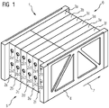
- the electrical device 1 comprises a plurality of power electronic modules 2a-2f, which can be connected to one another in a series circuit.
- An energy store 3a-3f is assigned to each of the modules 2a-2f.
- the electronic power module 2a can be electrically connected to the associated energy store 3a by means of a clamp connection.
- each of the other modules 2b-2f can be electrically connected to energy stores 3b-3f assigned to them.
- Both the modules 2a-2f and the energy stores 3a-3f have their own cuboid housing.
- the electrical device 1 also includes a support structure 4 .
- the modules 2a-2f and the energy stores 3a-3f are carried and supported by the support structure 4.
- the support structure 4 forms a support for a clamping device, by means of which the power electronic modules 2a-2f are mechanically clamped together in a mechanical clamp assembly.
- the modules 2a-2f are electrically connected to one another via connections 2a1-2f1 and 2a2-2f2, which are arranged on a front side 5 of the device 1.
- the energy stores 3a-3f are movably mounted in the support structure 4. Each energy store 3a-3f can be shifted in the direction of a rear side 6 of the electrical device 1. In the exemplary embodiment shown, this displacement takes place along a direction indicated by an arrow 7 .
- the procedure is as follows. First, the connection between the module 2b and the associated energy store 3b is released. For this purpose, the clamp connection by means of a corresponding tool via a suitable access route from above the supporting structure 4. If the connection is released, the energy store 2b is displaced in the direction of the arrow 7, so that the distance between the module 2b and the energy store 3b is increased. This enables a maintenance worker to loosen the clamping of the modules 2a-2f. Finally, the module 2b is removed from the support structure 4 and can be replaced, for example, by a fault-free module or a faulty component within the module by a fault-free component.
- FIG figure 2 shows a side view of the electrical device 1 of FIG figure 1 .
- Identical and similar components and elements are in the figures 1 and 2 provided with the same reference numbers.
- the electronic power module 2a is connected to the energy store 3a by means of a clamp connection 8 .
- the support structure 4 forms a fixed frame that supports the module 2a and the energy store 3a.
- the displacement of the energy storage device 3a takes place along guide rails, which figure 2 is indicated by a broken line 41.
- the maintenance worker can move the energy store 3a by means of a spindle system 42 without manual intervention in the support structure 4 .
- an arrangement 10 is shown in a side view, which comprises a first electrical device 11 and a second electrical device 12 .
- the first electrical device 11 includes a support structure 13 which is set up to accommodate a power electronic module 14 and an energy store 15 .
- the module 14 is arranged on a front side 16 of the device 11 .
- the supporting structure 13 is supported on the ground by means of insulating supports 17 and 18 .
- a second electrical device 12 embodied identically to the first electrical device 11 a power electronic module 19 and an energy store 20 is arranged with its front side 21 facing away from the first electrical device 11 .
- a maintenance platform 22 is installed on the front side of the first electrical equipment 11 for maintenance purposes. A positioning of the maintenance platform 22 between the two electrical devices 11 and 12 is not possible due to a lack of appropriate free space.
- a maintenance worker enters the maintenance platform for maintenance purposes.
- the energy store 15 can be moved to a rear side 23 of the first electrical device 11 after a connection 24 between the module 14 and the energy store 15 has been separated. Thereafter, the module 14 can be moved in the direction of an arrow 25 and removed from the support structure 13 .
Landscapes
- Engineering & Computer Science (AREA)
- Power Engineering (AREA)
- Battery Mounting, Suspending (AREA)
- Inverter Devices (AREA)
Description
- Die Erfindung betrifft eine elektrische Einrichtung mit einem leistungselektronischen Modul in einer Tragestruktur.
- Eine solche Einrichtung ist aus der
EP 2 800 133 A1 bekannt. Die bekannte elektrische Einrichtung bildet ein Ventil einer Hochspannungsgleichstromübertragungsanlage (HGÜ-Anlage). Das leistungselektronische Modul der bekannten elektrischen Einrichtung ist in Reihe mit weiteren, gleichartigen Modulen in einem Ventilturm angeordnet, das die Tragestruktur für das Modul darstellt. Das leistungselektronische Modul wird zu Wartungszwecken aus der Tragestruktur heraus bewegt. Das Modul kann dabei auf dazu eingerichteten Schienen aus der Tragestruktur zu deren Frontseite herausgefahren werden. - Die bekannte elektrische Einrichtung weist den Nachteil auf, dass sie nicht in einem modularen Mehrstufenumrichter einer HGÜ-Anlage eingesetzt werden kann.
- In einem modularen Mehrstufenumrichter umfasst die elektrische Einrichtung einen Energiespeicher, der parallel zum leistungselektronischen Modul geschaltet ist. Sowohl das leistungselektronische Modul als auch der Energiespeicher sind üblicherweise in der Tragestruktur räumlich nebeneinander angeordnet und miteinander elektrisch verbunden.
- Aus der
US 2016/0294166 A1 ist eine Anordnung mit einem leistungselektronischen Modul und einem Energiespeicher bekannt. Bei dieser bekannten Anordnung werden das Modul und der Energiespeicher in einem Wartungsfall gemeinsam aus der die beiden tragenden Tragestruktur frontal herausgefahren und danach voneinander getrennt. - Die Aufgabe der Erfindung besteht darin, eine artgemäße elektrische Einrichtung vorzuschlagen, die auch in einer HGÜ-Anlage mit einem modularen Mehrstufenumrichter einsetzbar ist.
- Die Aufgabe wird bei einer artgemäßen elektrischen Einrichtung dadurch gelöst, dass die elektrische Einrichtung ferner einen Energiespeicher umfasst, wobei der Energiespeicher und das leistungselektronischen Modul gemeinsam in der Tragestruktur angeordnet und miteinander lösbar verbunden sind, wobei der Energiespeicher bewegbar gelagert ist.
- Erfindungsgemäß kann demnach zu Wartungszwecken die Verbindung zwischen dem leistungselektronischen Modul und dem Energiespeicher gelöst werden, worauf der Energiespeicher innerhalb oder teilweise aus der Tragestruktur heraus verlagert werden kann.
- Ein Vorteil der erfindungsgemäßen elektrischen Einrichtung besteht darin, dass durch die ermöglichte Verlagerung des Energiespeichers genügend Freiraum geschaffen werden kann, um das leistungselektronische Modul aus der Tragestruktur herauszulösen. Auf diese Weise ist beispielsweise ein Austausch eines fehlerhaften Moduls ermöglicht.
- Erfindungsgemäß kann durch Bewegen des Energiespeichers ein Abstand zum leistungselektronischen Modul vergrößert werden. Beispielsweise kann die Tragestruktur eine Frontseite aufweisen, wobei an der Frontseite der Tragestruktur eine Wartungsbühne angeordnet werden kann. Bei Wartungsarbeiten an der elektrischen Einrichtung kann ein Wartungsarbeiter mittels der Wartungsbühne Zugang zur elektrischen Einrichtung erlangen. Das leistungselektronische Modul ist an der Frontseite angeordnet, wobei der Energiespeicher an einer Rückseite angeordnet ist. Dabei ist der Energiespeicher derart bewegbar gelagert, dass er zur Rückseite hin verlagerbar ist, wobei der Abstand zwischen dem Modul und dem Energiespeicher vergrößerbar ist. Bei dieser Anordnung kann das Modul zur Frontseite hin oder nach oben aus der Tragestruktur entnommen werden.
- Vorzugsweise umfasst die Tragestruktur Führungsschienen, so dass der Energiespeicher entlang der Führungsschienen verlagerbar ist. Die Führungsschienen können unterhalb und/oder oberhalb des Energiespeichers angeordnet sein. Die Führungsschienen erleichtern die Verlagerung des Energiespeichers und verhindern beispielsweise ein Verkanten während einer Verschiebung des Energiespeichers.
- Gemäß einer Ausführungsform der Erfindung umfasst die Einrichtung ein Spindelsystem zum Bewegen des Energiespeichers. Das Spindelsystem umfasst bevorzugt eine drehbare Spindel, die derart mit dem Energiespeicher verbunden ist, dass mittels einer Drehung der Spindel der Energiespeicher verlagerbar ist. Mit anderen Worten ist eine Drehbewegung einer drehbaren Spindel des Spindelsystems in eine Längsbewegung des Energiespeichers übertragbar. Das Spindelsystem kann beispielsweise durch einen Wartungsarbeiter bedienbar sein. Auf diese Weise kann der Wartungsarbeiter von einer Wartungsbühne aus den Energiespeicher verlagern, ohne selbst in die Tragestruktur eingreifen zu müssen. Das Spindelsystem kann ein Längs- oder ein Querspindelsystem sein.
- Bevorzugt ist die lösbare Verbindung zwischen Modul und Energiespeicher eine lösbare Klemmverbindung. Eine solche Klemmverbindung kann beispielsweise eine Klemme umfassen, die dazu eingerichtet ist, die Anschlüsse des Moduls und des Energiespeichers miteinander zu verklemmen. Eine Klemmverbindung stellt, insbesondere gegenüber einer Verschraubung, eine zuverlässige und zugleich leicht lösbare elektrische Verbindung dar. Vorteilhaft entfällt hierbei die Lösung massiver Schraubverbindungen, was den Zeitaufwand reduziert. Es werden zudem vorzugsweise keine losen Befestigungselemente verwendet, die bei Wartungsarbeiten aufwändig aufbewahrt werden müssen.
- Gemäß einer Ausführungsform der Erfindung umfasst das leistungselektronische Modul wenigstens einen Leistungshalbleiterschalter. Der Leistungshalbleiterschalter kann beispielsweise ein IGBT, IGCT oder dergleichen sein. Der Leistungshalbleiterschalter weist bevorzugt eine Spannungsfestigkeit von mehr als 1 kV auf.
- Der Energiespeicher kann beispielsweise ein Kondensator, insbesondere ein Leitungskondensator sein, der über ein eigenes Gehäuse verfügt.
- Gemäß einer Ausführungsform der Erfindung ist das leistungselektronische Modul in einem Spannverband mechanisch verspannt. Demnach umfasst die elektrische Einrichtung eine Mehrzahl von leistungselektronischen Modulen, die in einem Spannverband miteinander mechanisch verspannt sind. Die mechanische Verspannung erfolgt bevorzugt mittels einer Spannvorrichtung. Die Spannvorrichtung umfasst bevorzugt Druckstücke und Spannschrauben. Dabei kann die Tragestruktur zumindest einen Teil der Spannvorrichtung bilden. Die Spannschrauben stellen eine benötigte Spannkraft bereit. Die Druckstücke übertragen die mechanische Spannkraft auf die Module. Das leistungselektronische Modul kann mit den weiteren, beispielsweise gleichartig aufgebauten Modulen, sowie Kühlvorrichtungen und anderen Bauteilen den Spannverband bilden. Bei dieser Anordnung ist das leistungselektronische Modul fest im Spannverband fixiert. Eine Bewegbarkeit des Moduls zu dessen Entnahme aus der Tragestruktur in einem Wartungsfall ist ohne Weiteres nicht möglich. Erst durch die Bewegbarkeit des mit dem Modul verbundenen bzw. verbindbaren Energiespeichers ist eine Möglichkeit geschaffen, das Modul aus der Tragestruktur zu entfernen.
- Bevorzugt weist das Modul eine Arbeitsspannung von 1 kV bis 10 kV auf. Diese Arbeitsspannung liegt in einem Normalbetrieb des Moduls an seinen Anschlussklemmen an. Das Modul kann in einer Reihenschaltung mit weiteren, bevorzugt gleichartig aufgebauten Modulen zu einem Umrichterventil verschaltet sein. Die auf diese Weise erreichbare Gesamt-Arbeitsspannung des Umrichterventils kann bis über 1000 kV betragen.
- Die Erfindung betrifft des Weiteren ein Verfahren zum Warten einer elektrischen Einrichtung mit einem leistungselektronischen Modul sowie einem Energiespeicher, die gemeinsam in einer Tragestruktur angeordnet sind und miteinander lösbar verbunden sind.
- Die Aufgabe der Erfindung besteht darin, ein solches Verfahren vorzuschlagen, das eine möglichst einfache und zuverlässige Wartung der elektrischen Einrichtung ermöglicht.
- Die Aufgabe wird durch ein artgemäßes Verfahren gelöst, bei dem im Falle eines Fehlers des Moduls die Verbindung zwischen dem Modul und dem Energiespeicher gelöst wird, der Energiespeicher bewegt wird, wobei ein Abstand zwischen dem Energiespeicher und dem Modul vergrößert wird, und das Modul aus der Tragestruktur herausgenommen wird.
- Ein Vorteil des erfindungsgemäßen Verfahrens liegt darin, dass eine Wartung auch in Anlagen durchgeführt werden kann, wo das Modul nicht innerhalb der Tragestruktur bewegbar gelagert ist. Stattdessen kann durch die Verlagerung des bewegbar gelagerten Energiespeichers genügend Freiraum geschaffen werden, um das leistungselektronische Modul aus der Tragestruktur einfach und zuverlässig herauszulösen.
- Das erfindungsgemäße Verfahren ist selbstverständlich im Zusammenhang mit allen zuvor beschriebenen Varianten der erfindungsgemäßen elektrischen Einrichtung durchführbar.
- Die Erfindung soll im Folgenden anhand der
Figuren 1 bis 3 näher erläutert werden. -
Figur 1 zeigt ein Ausführungsbeispiel einer erfindungsgemäßen elektrischen Einrichtung in einer schematischen Übersichtsdarstellung; -
Figur 2 zeigt die erfindungsgemäße elektrische Einrichtung derFigur 1 in einer schematischen Seitenansicht; -
Figur 3 zeigt eine Anordnung zur Durchführung eines erfindungsgemäßen Verfahrens zur Wartung einer erfindungsgemäßen elektrischen Einrichtung in einer schematischen Darstellung. - Im Einzelnen ist in
Figur 1 eine elektrische Einrichtung 1 dargestellt. Die elektrische Einrichtung 1 umfasst eine Mehrzahl von leistungselektronischen Modulen 2a-2f, die ein einer Reihenschaltung miteinander verbindbar sind. Jedem der Module 2a-2f ist ein Energiespeicher 3a-3f zugeordnet. Das leistungselektronische Modul 2a ist mit dem zugeordneten Energiespeicher 3a mittels einer Klemmverbindung elektrisch verbindbar. Entsprechend sind jeder der übrigen Module 2b-2f mit ihnen zugeordneten Energiespeichern 3b-3f elektrisch verbindbar. Sowohl die Module 2a-2f als auch die Energiespeicher 3a-3f umfassen eigene, quaderförmige Gehäuse auf. - Die elektrische Einrichtung 1 umfasst ferner eine Tragestruktur 4 auf. Die Module 2a-2f und die Energiespeicher 3a-3f werden von der Tragestruktur 4 getragen und gestützt. Zudem bildet die Tragestruktur 4 eine Stützung für eine Spannvorrichtung, mittels der die leistungselektronischen Module 2a-2f in einem mechanischen Spannverband miteinander mechanisch verspannt sind. Die elektrische Verbindung der Module 2a-2f miteinander erfolgt über Anschlüsse 2a1-2f1 und 2a2-2f2, die zu einer Frontseite 5 der Einrichtung 1 angeordnet sind.
- Die Energiespeicher 3a-3f sind in der Tragestruktur 4 bewegbar gelagert. Dabei kann jeder Energiespeicher 3a-3f in Richtung zu einer Rückseite 6 der elektrischen Einrichtung 1 hin verlagert werden. Diese Verlagerung erfolgt im dargestellten Ausführungsbeispiel entlang einer mittels eines Pfeils 7 angedeuteten Richtung.
- Falls beispielsweise ein Austausch des Moduls 2b notwendig ist, wird folgendermaßen vorgegangen. Zunächst wird die Verbindung zwischen dem Modul 2b und dem zugeordneten Energiespeicher 3b gelöst. Dazu kann die Klemmverbindung mittels eines entsprechenden Werkzeugs über einen geeigneten Zugangsweg von oberhalb der Tragestruktur 4 gelöst werden. Ist die Verbindung gelöst, so wird der Energiespeicher 2b in Richtung des Pfeils 7 verlagert, so dass der Abstand zwischen dem Modul 2b und dem Energiespeicher 3b vergrößert wird. Dadurch wird es einem Wartungsarbeiter ermöglicht, den Spannverband der Module 2a-2f zu lockern. Schließlich wird das Modul 2b aus der Tragestruktur 4 herausgenommen und kann beispielsweise durch ein fehlerfreies Modul oder ein fehlerhaftes Bauteil innerhalb des Moduls durch ein fehlerfreies Bauteil ersetzt werden.
-
Figur 2 zeigt eine Seitenansicht der elektrischen Einrichtung 1 derFigur 1 . Gleiche und gleichartige Bauteile und Elemente sind in denFiguren 1 und2 mit gleichen Bezugszeichen versehen. Es ist erkennbar, dass das leistungselektronische Modul 2a mittels einer Klemmverbindung 8 mit dem Energiespeicher 3a verbunden ist. Die Tragestruktur 4 bildet einen festen Rahmen, der das Modul 2a und den Energiespeicher 3a trägt. - Die Verlagerung des Energiespeichers 3a erfolgt entlang von Führungsschienen, die in
Figur 2 mittels einer unterbrochenen Linie 41 angedeutet ist. Die Bewegung des Energiespeichers 3a kann vom Wartungsarbeiter mittels eines Spindelsystems 42 ohne manuellen Eingriff in die Tragestruktur 4 durchgeführt werden. - In
Figur 3 ist eine Anordnung 10 in einer Seitenansicht dargestellt, die eine erste elektrische Einrichtung 11 und eine zweite elektrische Einrichtung 12 umfasst. Die erste elektrische Einrichtung 11 umfasst eine Tragestruktur 13, die dazu eingerichtet ist, ein leistungselektronisches Modul 14 und einen Energiespeicher 15 aufzunehmen. Das Modul 14 ist zu einer Frontseite 16 der Einrichtung 11 angeordnet. Die Tragestruktur 13 ist mittels Isolierstützen 17 und 18 am Untergrund abgestützt. Eine zur ersten elektrischen Einrichtung 11 baugleich ausgebildete zweite elektrische Einrichtung 12 mit einem leistungselektronischen Modul 19 und einem Energiespeicher 20 ist mit ihrer Frontseite 21 zur ersten elektrischen Einrichtung 11 abgewandt angeordnet. - Eine Wartungsbühne 22 ist zu Wartungszwecken an der Frontseite der ersten elektrischen Einrichtung 11 aufgebaut. Eine Positionierung der Wartungsbühne 22 zwischen den beiden elektrischen Einrichtungen 11 und 12 ist aus Mangel an entsprechendem Freiraum nicht möglich.
- Zu Wartungszwecken betritt ein Wartungsarbeiter die Wartungsbühne. Mittels eines in
Figur 3 nicht dargestellten Spindelsystems kann der Energiespeicher 15 zu einer Rückseite 23 der ersten elektrischen Einrichtung 11 hin bewegt werden, nachdem eine Verbindung 24 zwischen dem Modul 14 und dem Energiespeicher 15 getrennt worden ist. Danach kann das Modul 14 in Richtung eines Pfeils 25 bewegt und aus der Tragstruktur 13 herausgenommen werden.
Claims (10)
- Elektrische Einrichtung (1) zum einsetzen in in einem modularen Mehrstufenumrichter einer Hochspannungsgleichstromübertragungsanlage, mit einem leistungselektronischen Modul (2a-2f) in einer Tragestruktur (4), wobei die elektrische Einrichtung (1) ferner einen Energiespeicher (3a-3f) umfasst, wobei der Energiespeicher (3a-3f) und das leistungselektronischen Modul (2a-2f) gemeinsam in der Tragestruktur (4) angeordnet und miteinander lösbar verbunden sind, wobei der Energiespeicher (3a-3f) bewegbar gelagert ist, wobeidas leistungselektronische Modul an einer Frontseite der Tragestruktur und der Energiespeicher an einer Rückseite der Tragestruktur angeordnet sind,dadurch gekennzeichnet, dass der Energiespeicher derart bewegbar gelagert ist, dass er zur Rückseite hin verlagerbar ist, wobeider Abstand zwischen dem Modul und dem Energiespeicher vergrößerbar ist.
- Elektrische Einrichtung (1) nach einem der vorangehenden Ansprüche, wobei die Tragestruktur (4) Führungsschienen (41) umfasst, so dass der Energiespeicher (3a-3f) entlang der Führungsschienen (41) verlagerbar ist.
- Elektrische Einrichtung (1) nach einem der vorangehenden Ansprüche, wobei die Einrichtung (1) ein Spindelsystem (42) zum Bewegen des Energiespeichers (3a-3f) umfasst.
- Elektrische Einrichtung (1) nach Anspruch 3, wobei eine Drehbewegung einer drehbaren Spindel des Spindelsystems (42) in eine Längsbewegung des Energiespeichers (3a-3f) übertragbar ist.
- Elektrische Einrichtung (1) nach einem der vorangehenden Ansprüche, wobei die lösbare Verbindung zwischen Modul (2a-2f) und Energiespeicher (3a-3f) eine lösbare Klemmverbindung ist.
- Elektrische Einrichtung (1) nach einem der vorangehenden Ansprüche, wobei das leistungselektronische Modul (2a-2f) wenigstens einen Leistungshalbleiterschalter umfasst.
- Elektrische Einrichtung (1) nach einem der vorangehenden Ansprüche, wobei der Energiespeicher (3a-3f) ein Kondensator ist.
- Elektrische Einrichtung (1) nach einem der vorangehenden Ansprüche, wobei das leistungselektronische Modul (2a-2f) mit weiteren leistungselektronischen Modulen (2a-2f) in einem Spannverband mechanisch verspannt ist.
- Elektrische Einrichtung (1) nach einem der vorangehenden Ansprüche, wobei das Modul (2a-2f) eine Arbeitsspannung von 1 kV bis 10 kV aufweist.
- Verfahren zum Warten einer elektrischen Einrichtung (1) gemäss Einspruch 1, mit einem leistungselektronischen Modul (2a-2f) sowie einem Energiespeicher (3a-3f), die gemeinsam in einer Tragestruktur (4) angeordnet sind und miteinander lösbar verbunden sind, bei dem im Falle eines Fehlers des Moduls (2a-2f)- die Verbindung (8) zwischen dem Modul (21-2f) und dem Energiespeicher (3a-3f) gelöst wird, worauf- der Energiespeicher (3a-3f) zu einer Rückseite der Tragestruktur bewegt wird, wobei ein Abstand zwischen dem Energiespeicher (3a-3f) und dem Modul (2a-2f) vergrößert wird,- das Modul (2a-2f) aus der Tragestruktur (4) herausgenommen wird.
Applications Claiming Priority (2)
| Application Number | Priority Date | Filing Date | Title |
|---|---|---|---|
| DE102016221405.5A DE102016221405A1 (de) | 2016-10-31 | 2016-10-31 | Elektrische Einrichtung und Verfahren zu deren Wartung |
| PCT/EP2017/076549 WO2018077680A1 (de) | 2016-10-31 | 2017-10-18 | Elektrische einrichtung und verfahren zu deren wartung |
Publications (2)
| Publication Number | Publication Date |
|---|---|
| EP3507882A1 EP3507882A1 (de) | 2019-07-10 |
| EP3507882B1 true EP3507882B1 (de) | 2022-05-11 |
Family
ID=60269800
Family Applications (1)
| Application Number | Title | Priority Date | Filing Date |
|---|---|---|---|
| EP17794906.2A Active EP3507882B1 (de) | 2016-10-31 | 2017-10-18 | Elektrische einrichtung und verfahren zu deren wartung |
Country Status (4)
| Country | Link |
|---|---|
| EP (1) | EP3507882B1 (de) |
| CN (1) | CN210142905U (de) |
| DE (1) | DE102016221405A1 (de) |
| WO (1) | WO2018077680A1 (de) |
Families Citing this family (1)
| Publication number | Priority date | Publication date | Assignee | Title |
|---|---|---|---|---|
| EP3813216A1 (de) * | 2019-10-23 | 2021-04-28 | Siemens Energy Global GmbH & Co. KG | Vorrichtung zum stabilisieren eines gleichspannungsnetzes |
Family Cites Families (8)
| Publication number | Priority date | Publication date | Assignee | Title |
|---|---|---|---|---|
| US5366827A (en) * | 1992-06-10 | 1994-11-22 | Digital Equipment Corporation | Modular housing for batteries and battery charger |
| JPH07176687A (ja) * | 1993-12-20 | 1995-07-14 | Toshiba Corp | サイリスタバルブ |
| EP2624412A1 (de) * | 2012-02-06 | 2013-08-07 | Siemens Aktiengesellschaft | Stromversorgung |
| KR101758417B1 (ko) | 2013-04-30 | 2017-07-17 | 엘에스산전 주식회사 | Hvdc 밸브 타워 |
| CN103354232B (zh) * | 2013-06-17 | 2015-08-26 | 许继电气股份有限公司 | 一种用于柔性直流输电的并联子模块 |
| KR101623347B1 (ko) * | 2013-12-30 | 2016-06-07 | 주식회사 효성 | 초고압 직류 송전시스템의 모듈 인출장치 |
| DE202014100434U1 (de) * | 2014-01-31 | 2014-02-12 | Rhomberg Bahntechnik Gmbh | Elektrische Schaltvorrichtung |
| KR101645471B1 (ko) * | 2014-08-05 | 2016-08-04 | 주식회사 효성 | 초고압 직류 송전시스템의 모듈 교체장치 |
-
2016
- 2016-10-31 DE DE102016221405.5A patent/DE102016221405A1/de not_active Withdrawn
-
2017
- 2017-10-18 CN CN201790001374.2U patent/CN210142905U/zh not_active Expired - Fee Related
- 2017-10-18 EP EP17794906.2A patent/EP3507882B1/de active Active
- 2017-10-18 WO PCT/EP2017/076549 patent/WO2018077680A1/de not_active Ceased
Also Published As
| Publication number | Publication date |
|---|---|
| DE102016221405A1 (de) | 2018-05-03 |
| EP3507882A1 (de) | 2019-07-10 |
| CN210142905U (zh) | 2020-03-13 |
| WO2018077680A1 (de) | 2018-05-03 |
Similar Documents
| Publication | Publication Date | Title |
|---|---|---|
| DE69513909T2 (de) | Steuervorrichtung für industrieroboter | |
| DE102018203489B4 (de) | Wechselstromladevorrichtung für ein Kraftfahrzeug und Verfahren zum Betreiben einer Wechselstromladevorrichtung für ein Kraftfahrzeug | |
| DE69932764T2 (de) | Abpassbare Abgangsbaugruppe einer Niederspannungs-Schaltzelle | |
| EP3507882B1 (de) | Elektrische einrichtung und verfahren zu deren wartung | |
| DE102017217418A1 (de) | Steuergerät, Antriebseinrichtung | |
| DE102013218508A1 (de) | Vorrichtung zur Verbindung einer ersten Stromschiene mit einer zweiten Stromschiene | |
| EP0624939B1 (de) | Kontaktanordnung für einschiebbare Leistungsschalter in Schaltanlagen | |
| EP0821841B1 (de) | Anordnung zum anschluss von versorgungsleitungen an ein elektronisches gerät sowie schrank mit einer derartigen anordnung | |
| DE19816589C1 (de) | Mehrfeldrige Schaltanlage mit einer Sammelschienenanordnung | |
| DE102020134453A1 (de) | Anordnung zur Integration in eine Ladevorrichtung für wenigstens ein Elektrofahrzeug | |
| DE102007047652A1 (de) | Batteriegerät mit separaten Batterieeinheiten | |
| DE102010032522A1 (de) | Klemmanordnung für einen Leistungsschalter in Federzugtechnik | |
| EP2248236A1 (de) | Mittel- oder hochspannungsschaltanlage | |
| EP1045497B1 (de) | Adaptersystem für modulare Lastabgänge | |
| DE102016203107B4 (de) | Modul für einen modularen Multi-Level Konverter oder für eine HGÜ-Anlage | |
| EP3417482B1 (de) | Elektrische einrichtung mit einer halbleiterschaltung | |
| DE4126786C2 (de) | Elektrische Mittelspannungsschaltanlage | |
| DE102022130031B3 (de) | Elektrische Kontaktierungsvorrichtung für einen elektrischen Energiespeicher eines zumindest teilweise elektrisch betriebenen Kraftfahrzeugs, elektrische Energiespeicher sowie Kraftfahrzeug | |
| LU505807B1 (de) | Flexibles Fernmeldesystem | |
| EP2867958B1 (de) | Elektrisches gerät mit einer hutschienenaufnahme und einem leiteranschluss | |
| EP4086121A1 (de) | Schienenfahrzeug mit werkzeuglosem erdungskonzept | |
| EP0478098B1 (de) | Gasisolierte Mittelspannungs-Schaltanlage mit Durchführungen zur Herstellung einer äusseren Erdverbindung | |
| DE102023135452A1 (de) | Flexibles Fernmeldesystem | |
| EP1356557A1 (de) | Schaltschränke für verkehrseinrichtungen | |
| DE102021120084A1 (de) | Ladeanordnung zum Laden von Fahrzeugen, Verfahren zum Laden eines Fahrzeugs |
Legal Events
| Date | Code | Title | Description |
|---|---|---|---|
| STAA | Information on the status of an ep patent application or granted ep patent |
Free format text: STATUS: UNKNOWN |
|
| STAA | Information on the status of an ep patent application or granted ep patent |
Free format text: STATUS: THE INTERNATIONAL PUBLICATION HAS BEEN MADE |
|
| PUAI | Public reference made under article 153(3) epc to a published international application that has entered the european phase |
Free format text: ORIGINAL CODE: 0009012 |
|
| STAA | Information on the status of an ep patent application or granted ep patent |
Free format text: STATUS: REQUEST FOR EXAMINATION WAS MADE |
|
| 17P | Request for examination filed |
Effective date: 20190402 |
|
| AK | Designated contracting states |
Kind code of ref document: A1 Designated state(s): AL AT BE BG CH CY CZ DE DK EE ES FI FR GB GR HR HU IE IS IT LI LT LU LV MC MK MT NL NO PL PT RO RS SE SI SK SM TR |
|
| AX | Request for extension of the european patent |
Extension state: BA ME |
|
| DAV | Request for validation of the european patent (deleted) | ||
| DAX | Request for extension of the european patent (deleted) | ||
| RAP1 | Party data changed (applicant data changed or rights of an application transferred) |
Owner name: SIEMENS ENERGY GLOBAL GMBH & CO. KG |
|
| GRAP | Despatch of communication of intention to grant a patent |
Free format text: ORIGINAL CODE: EPIDOSNIGR1 |
|
| STAA | Information on the status of an ep patent application or granted ep patent |
Free format text: STATUS: GRANT OF PATENT IS INTENDED |
|
| INTG | Intention to grant announced |
Effective date: 20211221 |
|
| GRAS | Grant fee paid |
Free format text: ORIGINAL CODE: EPIDOSNIGR3 |
|
| GRAA | (expected) grant |
Free format text: ORIGINAL CODE: 0009210 |
|
| STAA | Information on the status of an ep patent application or granted ep patent |
Free format text: STATUS: THE PATENT HAS BEEN GRANTED |
|
| AK | Designated contracting states |
Kind code of ref document: B1 Designated state(s): AL AT BE BG CH CY CZ DE DK EE ES FI FR GB GR HR HU IE IS IT LI LT LU LV MC MK MT NL NO PL PT RO RS SE SI SK SM TR |
|
| REG | Reference to a national code |
Ref country code: GB Ref legal event code: FG4D Free format text: NOT ENGLISH |
|
| REG | Reference to a national code |
Ref country code: CH Ref legal event code: EP |
|
| REG | Reference to a national code |
Ref country code: AT Ref legal event code: REF Ref document number: 1492293 Country of ref document: AT Kind code of ref document: T Effective date: 20220515 |
|
| REG | Reference to a national code |
Ref country code: DE Ref legal event code: R096 Ref document number: 502017013180 Country of ref document: DE |
|
| REG | Reference to a national code |
Ref country code: IE Ref legal event code: FG4D Free format text: LANGUAGE OF EP DOCUMENT: GERMAN |
|
| REG | Reference to a national code |
Ref country code: LT Ref legal event code: MG9D |
|
| REG | Reference to a national code |
Ref country code: NL Ref legal event code: MP Effective date: 20220511 |
|
| PG25 | Lapsed in a contracting state [announced via postgrant information from national office to epo] |
Ref country code: SE Free format text: LAPSE BECAUSE OF FAILURE TO SUBMIT A TRANSLATION OF THE DESCRIPTION OR TO PAY THE FEE WITHIN THE PRESCRIBED TIME-LIMIT Effective date: 20220511 Ref country code: PT Free format text: LAPSE BECAUSE OF FAILURE TO SUBMIT A TRANSLATION OF THE DESCRIPTION OR TO PAY THE FEE WITHIN THE PRESCRIBED TIME-LIMIT Effective date: 20220912 Ref country code: NO Free format text: LAPSE BECAUSE OF FAILURE TO SUBMIT A TRANSLATION OF THE DESCRIPTION OR TO PAY THE FEE WITHIN THE PRESCRIBED TIME-LIMIT Effective date: 20220811 Ref country code: NL Free format text: LAPSE BECAUSE OF FAILURE TO SUBMIT A TRANSLATION OF THE DESCRIPTION OR TO PAY THE FEE WITHIN THE PRESCRIBED TIME-LIMIT Effective date: 20220511 Ref country code: LT Free format text: LAPSE BECAUSE OF FAILURE TO SUBMIT A TRANSLATION OF THE DESCRIPTION OR TO PAY THE FEE WITHIN THE PRESCRIBED TIME-LIMIT Effective date: 20220511 Ref country code: HR Free format text: LAPSE BECAUSE OF FAILURE TO SUBMIT A TRANSLATION OF THE DESCRIPTION OR TO PAY THE FEE WITHIN THE PRESCRIBED TIME-LIMIT Effective date: 20220511 Ref country code: GR Free format text: LAPSE BECAUSE OF FAILURE TO SUBMIT A TRANSLATION OF THE DESCRIPTION OR TO PAY THE FEE WITHIN THE PRESCRIBED TIME-LIMIT Effective date: 20220812 Ref country code: FI Free format text: LAPSE BECAUSE OF FAILURE TO SUBMIT A TRANSLATION OF THE DESCRIPTION OR TO PAY THE FEE WITHIN THE PRESCRIBED TIME-LIMIT Effective date: 20220511 Ref country code: ES Free format text: LAPSE BECAUSE OF FAILURE TO SUBMIT A TRANSLATION OF THE DESCRIPTION OR TO PAY THE FEE WITHIN THE PRESCRIBED TIME-LIMIT Effective date: 20220511 Ref country code: BG Free format text: LAPSE BECAUSE OF FAILURE TO SUBMIT A TRANSLATION OF THE DESCRIPTION OR TO PAY THE FEE WITHIN THE PRESCRIBED TIME-LIMIT Effective date: 20220811 |
|
| PG25 | Lapsed in a contracting state [announced via postgrant information from national office to epo] |
Ref country code: RS Free format text: LAPSE BECAUSE OF FAILURE TO SUBMIT A TRANSLATION OF THE DESCRIPTION OR TO PAY THE FEE WITHIN THE PRESCRIBED TIME-LIMIT Effective date: 20220511 Ref country code: PL Free format text: LAPSE BECAUSE OF FAILURE TO SUBMIT A TRANSLATION OF THE DESCRIPTION OR TO PAY THE FEE WITHIN THE PRESCRIBED TIME-LIMIT Effective date: 20220511 Ref country code: LV Free format text: LAPSE BECAUSE OF FAILURE TO SUBMIT A TRANSLATION OF THE DESCRIPTION OR TO PAY THE FEE WITHIN THE PRESCRIBED TIME-LIMIT Effective date: 20220511 Ref country code: IS Free format text: LAPSE BECAUSE OF FAILURE TO SUBMIT A TRANSLATION OF THE DESCRIPTION OR TO PAY THE FEE WITHIN THE PRESCRIBED TIME-LIMIT Effective date: 20220911 |
|
| PG25 | Lapsed in a contracting state [announced via postgrant information from national office to epo] |
Ref country code: SM Free format text: LAPSE BECAUSE OF FAILURE TO SUBMIT A TRANSLATION OF THE DESCRIPTION OR TO PAY THE FEE WITHIN THE PRESCRIBED TIME-LIMIT Effective date: 20220511 Ref country code: SK Free format text: LAPSE BECAUSE OF FAILURE TO SUBMIT A TRANSLATION OF THE DESCRIPTION OR TO PAY THE FEE WITHIN THE PRESCRIBED TIME-LIMIT Effective date: 20220511 Ref country code: RO Free format text: LAPSE BECAUSE OF FAILURE TO SUBMIT A TRANSLATION OF THE DESCRIPTION OR TO PAY THE FEE WITHIN THE PRESCRIBED TIME-LIMIT Effective date: 20220511 Ref country code: EE Free format text: LAPSE BECAUSE OF FAILURE TO SUBMIT A TRANSLATION OF THE DESCRIPTION OR TO PAY THE FEE WITHIN THE PRESCRIBED TIME-LIMIT Effective date: 20220511 Ref country code: DK Free format text: LAPSE BECAUSE OF FAILURE TO SUBMIT A TRANSLATION OF THE DESCRIPTION OR TO PAY THE FEE WITHIN THE PRESCRIBED TIME-LIMIT Effective date: 20220511 Ref country code: CZ Free format text: LAPSE BECAUSE OF FAILURE TO SUBMIT A TRANSLATION OF THE DESCRIPTION OR TO PAY THE FEE WITHIN THE PRESCRIBED TIME-LIMIT Effective date: 20220511 |
|
| REG | Reference to a national code |
Ref country code: DE Ref legal event code: R097 Ref document number: 502017013180 Country of ref document: DE |
|
| PLBE | No opposition filed within time limit |
Free format text: ORIGINAL CODE: 0009261 |
|
| STAA | Information on the status of an ep patent application or granted ep patent |
Free format text: STATUS: NO OPPOSITION FILED WITHIN TIME LIMIT |
|
| PG25 | Lapsed in a contracting state [announced via postgrant information from national office to epo] |
Ref country code: AL Free format text: LAPSE BECAUSE OF FAILURE TO SUBMIT A TRANSLATION OF THE DESCRIPTION OR TO PAY THE FEE WITHIN THE PRESCRIBED TIME-LIMIT Effective date: 20220511 |
|
| 26N | No opposition filed |
Effective date: 20230214 |
|
| PG25 | Lapsed in a contracting state [announced via postgrant information from national office to epo] |
Ref country code: SI Free format text: LAPSE BECAUSE OF FAILURE TO SUBMIT A TRANSLATION OF THE DESCRIPTION OR TO PAY THE FEE WITHIN THE PRESCRIBED TIME-LIMIT Effective date: 20220511 Ref country code: MC Free format text: LAPSE BECAUSE OF FAILURE TO SUBMIT A TRANSLATION OF THE DESCRIPTION OR TO PAY THE FEE WITHIN THE PRESCRIBED TIME-LIMIT Effective date: 20220511 |
|
| REG | Reference to a national code |
Ref country code: CH Ref legal event code: PL |
|
| REG | Reference to a national code |
Ref country code: BE Ref legal event code: MM Effective date: 20221031 |
|
| PG25 | Lapsed in a contracting state [announced via postgrant information from national office to epo] |
Ref country code: LU Free format text: LAPSE BECAUSE OF NON-PAYMENT OF DUE FEES Effective date: 20221018 |
|
| PG25 | Lapsed in a contracting state [announced via postgrant information from national office to epo] |
Ref country code: LI Free format text: LAPSE BECAUSE OF NON-PAYMENT OF DUE FEES Effective date: 20221031 Ref country code: CH Free format text: LAPSE BECAUSE OF NON-PAYMENT OF DUE FEES Effective date: 20221031 |
|
| PG25 | Lapsed in a contracting state [announced via postgrant information from national office to epo] |
Ref country code: BE Free format text: LAPSE BECAUSE OF NON-PAYMENT OF DUE FEES Effective date: 20221031 |
|
| PG25 | Lapsed in a contracting state [announced via postgrant information from national office to epo] |
Ref country code: IE Free format text: LAPSE BECAUSE OF NON-PAYMENT OF DUE FEES Effective date: 20221018 |
|
| REG | Reference to a national code |
Ref country code: AT Ref legal event code: MM01 Ref document number: 1492293 Country of ref document: AT Kind code of ref document: T Effective date: 20221018 |
|
| PG25 | Lapsed in a contracting state [announced via postgrant information from national office to epo] |
Ref country code: IT Free format text: LAPSE BECAUSE OF FAILURE TO SUBMIT A TRANSLATION OF THE DESCRIPTION OR TO PAY THE FEE WITHIN THE PRESCRIBED TIME-LIMIT Effective date: 20220511 Ref country code: AT Free format text: LAPSE BECAUSE OF NON-PAYMENT OF DUE FEES Effective date: 20221018 |
|
| PGFP | Annual fee paid to national office [announced via postgrant information from national office to epo] |
Ref country code: FR Payment date: 20231026 Year of fee payment: 7 |
|
| PG25 | Lapsed in a contracting state [announced via postgrant information from national office to epo] |
Ref country code: HU Free format text: LAPSE BECAUSE OF FAILURE TO SUBMIT A TRANSLATION OF THE DESCRIPTION OR TO PAY THE FEE WITHIN THE PRESCRIBED TIME-LIMIT; INVALID AB INITIO Effective date: 20171018 |
|
| PG25 | Lapsed in a contracting state [announced via postgrant information from national office to epo] |
Ref country code: CY Free format text: LAPSE BECAUSE OF FAILURE TO SUBMIT A TRANSLATION OF THE DESCRIPTION OR TO PAY THE FEE WITHIN THE PRESCRIBED TIME-LIMIT Effective date: 20220511 |
|
| PG25 | Lapsed in a contracting state [announced via postgrant information from national office to epo] |
Ref country code: MK Free format text: LAPSE BECAUSE OF FAILURE TO SUBMIT A TRANSLATION OF THE DESCRIPTION OR TO PAY THE FEE WITHIN THE PRESCRIBED TIME-LIMIT Effective date: 20220511 |
|
| PG25 | Lapsed in a contracting state [announced via postgrant information from national office to epo] |
Ref country code: MT Free format text: LAPSE BECAUSE OF FAILURE TO SUBMIT A TRANSLATION OF THE DESCRIPTION OR TO PAY THE FEE WITHIN THE PRESCRIBED TIME-LIMIT Effective date: 20220511 |
|
| PG25 | Lapsed in a contracting state [announced via postgrant information from national office to epo] |
Ref country code: BG Free format text: LAPSE BECAUSE OF FAILURE TO SUBMIT A TRANSLATION OF THE DESCRIPTION OR TO PAY THE FEE WITHIN THE PRESCRIBED TIME-LIMIT Effective date: 20220511 |
|
| PG25 | Lapsed in a contracting state [announced via postgrant information from national office to epo] |
Ref country code: BG Free format text: LAPSE BECAUSE OF FAILURE TO SUBMIT A TRANSLATION OF THE DESCRIPTION OR TO PAY THE FEE WITHIN THE PRESCRIBED TIME-LIMIT Effective date: 20220511 |
|
| PG25 | Lapsed in a contracting state [announced via postgrant information from national office to epo] |
Ref country code: FR Free format text: LAPSE BECAUSE OF NON-PAYMENT OF DUE FEES Effective date: 20241031 |
|
| PG25 | Lapsed in a contracting state [announced via postgrant information from national office to epo] |
Ref country code: TR Free format text: LAPSE BECAUSE OF FAILURE TO SUBMIT A TRANSLATION OF THE DESCRIPTION OR TO PAY THE FEE WITHIN THE PRESCRIBED TIME-LIMIT Effective date: 20220511 |
|
| PGFP | Annual fee paid to national office [announced via postgrant information from national office to epo] |
Ref country code: DE Payment date: 20251028 Year of fee payment: 9 |
|
| PGFP | Annual fee paid to national office [announced via postgrant information from national office to epo] |
Ref country code: GB Payment date: 20251023 Year of fee payment: 9 |