EP3507578B1 - A device for temperature limit indication and detection of temperature-sensitive items - Google Patents
A device for temperature limit indication and detection of temperature-sensitive items Download PDFInfo
- Publication number
- EP3507578B1 EP3507578B1 EP17844689.4A EP17844689A EP3507578B1 EP 3507578 B1 EP3507578 B1 EP 3507578B1 EP 17844689 A EP17844689 A EP 17844689A EP 3507578 B1 EP3507578 B1 EP 3507578B1
- Authority
- EP
- European Patent Office
- Prior art keywords
- sensor
- reservoir
- temperature
- fluid
- microfluidic
- Prior art date
- Legal status (The legal status is an assumption and is not a legal conclusion. Google has not performed a legal analysis and makes no representation as to the accuracy of the status listed.)
- Active
Links
Images

Classifications
-
- G—PHYSICS
- G01—MEASURING; TESTING
- G01K—MEASURING TEMPERATURE; MEASURING QUANTITY OF HEAT; THERMALLY-SENSITIVE ELEMENTS NOT OTHERWISE PROVIDED FOR
- G01K11/00—Measuring temperature based upon physical or chemical changes not covered by groups G01K3/00, G01K5/00, G01K7/00 or G01K9/00
- G01K11/06—Measuring temperature based upon physical or chemical changes not covered by groups G01K3/00, G01K5/00, G01K7/00 or G01K9/00 using melting, freezing, or softening
-
- B—PERFORMING OPERATIONS; TRANSPORTING
- B65—CONVEYING; PACKING; STORING; HANDLING THIN OR FILAMENTARY MATERIAL
- B65D—CONTAINERS FOR STORAGE OR TRANSPORT OF ARTICLES OR MATERIALS, e.g. BAGS, BARRELS, BOTTLES, BOXES, CANS, CARTONS, CRATES, DRUMS, JARS, TANKS, HOPPERS, FORWARDING CONTAINERS; ACCESSORIES, CLOSURES, OR FITTINGS THEREFOR; PACKAGING ELEMENTS; PACKAGES
- B65D79/00—Kinds or details of packages, not otherwise provided for
- B65D79/02—Arrangements or devices for indicating incorrect storage or transport
Definitions
- This invention relates to a device for indicating violation of a temperature limit of an item and a system and method for detecting the temperature limit violation. It relates particularly but not exclusively to a device that enables permanent machine-readable indication of temperature limit violations that occur during storage, processing and transportation of temperature-sensitive items.
- Certain biological samples are required to be maintained at very low temperatures for long-term storage, such as red blood cells, plasma, bacterial or viral strains, embryos, gametes and extracted DNA to name a few. These samples are typically required to be maintained at temperatures of less than -60°C to -200°C. To achieve this, the samples are usually placed in vials, bags, cassettes or other similar vessels and stored within mechanical freezers or in dry ice at temperatures of -60°C to -150°C, or within cryogenic tanks containing liquid nitrogen at temperatures of less than -150°C. Storage at these temperatures ensures sample integrity, thereby maximising the likelihood of cell viability when thawed.
- Different biological samples have different critical temperatures, that is, a temperature above which changes may occur at the cellular structure level and hence above which the biological sample may degrade.
- the sample does not necessarily thaw to be above its critical temperature, usually considered to be the glass transition temperature of water, and may suffer cellular damage whilst remaining in the frozen state. It is generally accepted that the sample must be held below its critical temperature at all times from when it is first frozen to intentionally thawed in a controlled manner for final processing.
- a typical standard for frozen food products is that they must be stored and handled at temperatures less than - 18°C. That is, each type of item will be subject to a different critical temperature value or range to ensure it remains viable. After being frozen and stabilised at a safe temperature, further storage, processing or transport must ensure that the item is held below its critical temperature. The failure to do so may render the items unviable, resulting in loss of items having significant monetary value and/or importance, such as drugs for medical treatment.
- Temperature loggers are small electronic devices which incorporate a sensing element, such as a thermistor or thermocouple, with electronic circuits and a memory to record temperature readings over time. Typically, these devices are interrogated wirelessly to download the thermal history, which is then separately processed to flag any temperature limit violations. However, temperature loggers do not provide a permanent record of temperature limit violations, thereby risking tampering or loss of the recorded data and introduction of inaccuracies during processing.
- Temperature loggers must be removed from the item or storage environment for interrogation of the recorded data. This process may risk exposure of the item to ambient temperatures that may render it unviable. Temperature loggers may also not be in close contact with the item due to size limitations. Accordingly, a short temperature excursion may result in a false negative indication as the item itself has not experienced a critical rise in temperature. Such inaccuracy may cause items to be erroneously identified as unviable. Temperature loggers are also limited to use in storage temperatures above -40°C and thus cannot be used for ultra-cold (less than -60°C) or cryogenic conditions.
- Temperature indicator strips are used in cold chain logistics for identifying temperature limit violations of items requiring storage at temperatures of 0°C to - 60°C, such as food products and pharmaceuticals. Th e indicator strips are typically stickers that are either adhered to an item or a container storing an item and utilise a chemical reaction to change colour in a predetermined temperature range.
- temperature indicator vials are used in cryogenic storage of various items and include a heat-sensitive material that changes colour in a predetermined temperature range. The indicator strips or vials are selected for use with an item based on their temperature range corresponding to the item's critical temperature value or range.
- US7275863 B1 discloses threshold calorimeter/shelf life monitors having a thermally moderating housing containing a liquid solution and one or more low melting point solids all having properties correlated relative to one another and calibrated to closely match a thermal decay profile (time-temperature profile) of perishable products being monitored and indicate, by a change in colour, electrical capacitance and/or impedance, transmitted RF signals, or a combination thereof, the cumulative thermal history of the product while in transit or storage and whether its time-temperature profile has been violated to a detrimental extent or if a significant amount of shelf life has been consumed.
- a thermal decay profile time-temperature profile
- EP0545274 A1 describes an indicator that reveals if a frozen product has exited the required temperature range.
- the indicator comprises a small transparent plastic bag that includes two separate compartments. The internal separation of the compartments is crossed by one or more capillary channels. One of the compartments is filled with an eutectic liquid, the other compartment has a hydrophilic material.
- temperature indicator strips or vials provide a permanent visual indication of temperature limit violations.
- this requires human operators to observe and react to the indicator colour change, thus leading to potential human error.
- it may be difficult to observe the indicator in frosted conditions in which the item is stored.
- the item may also require removal from storage in order to observe the indicator, which may expose the item to ambient temperatures rendering it unviable.
- the indicator strips or vials may not be in close contact with the item due to size limitations, which may cause false negative indications as described above.
- the present invention provides a device for indicating violation of a temperature limit of an item, wherein the device is positionable near the item and includes a sensor configured to change its state permanently when the temperature limit is violated, wherein the change in sensor state is machine-readable to provide a permanent indication of the temperature limit violation, the sensor including: a reservoir for storing a fluid that changes phase from a solid to a liquid when the temperature limit is violated; and a channel in fluid communication with the reservoir for receiving flow of the fluid in liquid phase from the reservoir, wherein the sensor is arranged to allow flow of the fluid in the liquid phase such that the state of the sensor is permanently changed, and wherein the sensor is further configured to prevent the fluid flow from permanently changing the sensor state until activation of the sensor from a resting state.
- the device ensures that a permanent record of the temperature limit violation is made due to the permanent change in sensor state, which is machine-readable for processing at a later time.
- the change in sensor state may be machine-read at any time during the supply chain, such as during storage, processing and/or transportation of the item. Accordingly, the device more accurately and reliably indicates temperature limit violations than the prior art devices since it is not reliant on human operators to observe visual indicators or process data records to identify temperature limit violations.
- the senor includes a barrier for preventing the fluid flow from permanently changing the sensor state, the barrier being removable to activate the sensor from the resting state.
- the sensor may be activated from the resting state to an activated state.
- the barrier may include one of a seal, a membrane or a valve.
- the barrier is positioned between the reservoir and the channel to prevent the fluid stored in the reservoir from flowing into the channel. Additionally/alternatively, the barrier may be positioned within the channel or at an end of the channel other than the reservoir end.
- the senor may include a ventilation path for equalising the pressure within the sensor to allow fluid flow therethrough.
- the ventilation path may be in fluid communication with at least the reservoir.
- the barrier may be positioned at least one of: between the reservoir and the ventilation path; at an end of the ventilation path other than the reservoir end; or within the ventilation path.
- the barrier may be automatically removable to activate the sensor by at least one of: the barrier including a temperature-dependent material that degrades or shrinks at a desired temperature; and the sensor further including a gas-filled capsule that contracts to remove a force on the barrier at a desired temperature.
- the barrier may also be manually removable to activate the sensor by at least one of: the barrier including a magnetic material to which a magnetic field can be applied and/or removed to alter a magnetic force on the barrier; and the barrier being coupled to an external actuator that is operable to apply and/or remove a force on the barrier.
- the barrier may be constructed of a small ball bearing that when placed in a sufficient magnetic field causes the ball to be trapped between e.g. the reservoir and the channel.
- the sensor may change its state from an activated state to a triggered state when the temperature limit is violated.
- the change in sensor state is permanent and the sensor is unable to revert to the activated state.
- the channel of the sensor may be sized and shaped such that capillary forces drive the fluid flow from the reservoir into the channel.
- the sensor may be microfluidic-based and the channel may be a microfluidic channel dimensioned such that capillary forces drive the fluid flow.
- the channel may also include a hydrophilic surface to encourage fluid flow from the reservoir into the channel. This may be achieved through oxygen plasma etching of the channel.
- the reservoir may include a hydrophobic surface to encourage fluid flow from the reservoir into the channel.
- the reservoir may include a hydrophobic coating.
- the sensor may be constructed of a supporting layer and additional layers bonded onto the supporting layer that enclose at least the reservoir and the channel. Preferably, a capacitor, inductor and electric circuit of the sensor are also enclosed by the additional layers bonded onto the supporting layer.
- the device may also include a thermally conductive enclosure housing the sensor for providing close thermal contact with the item. This beneficially reduces the likelihood of false negative indications since the temperature in the sensor will correspond closely with the actual temperature of the item.
- the fluid stored in the sensor may be a single fluid or combination of fluids selected to have a desired melting point corresponding to the temperature limit of the item.
- the fluid is an aqueous solution.
- the fluid may be a 70% ethanol solution with a melting point of about -50°C.
- the device includes two or more sensors and each sensor stores a different fluid for indicating violation of more than one temperature limit of the item.
- the temperature limit of the item may be a single temperature or range of temperatures.
- the sensor is arranged to allow flow of the fluid in the liquid phase such that the state of the sensor is permanently changed. That is, the sensor state is not resettable if the item's temperature no longer exceeds the temperature limit, i.e. the critical temperature value or range for the item.
- the fluid flow causes a permanent change in a property of the sensor.
- the property includes an electrical property selected from one of a group including: impedance, resistance, capacitance and inductance.
- the senor includes a capacitor and the fluid flow causes a permanent change in capacitance.
- the fluid flow may be either driven towards or away from conductors of the capacitor to cause the permanent change in capacitance.
- the capacitor may be positioned in fluid communication with the channel such that the fluid flow is driven towards the conductors of the capacitor.
- the capacitor may be positioned within the channel or at an end of the channel other than the reservoir end, such as opposite the reservoir.
- the capacitor may be positioned within the reservoir such that the fluid flow is driven away from the conductors of the capacitor.
- the conductors of the capacitor are permanently changed as a result of the fluid flow thereacross.
- the sensor may also include an electrical circuit connected to the capacitor that is configured to provide a machine-readable indicator of the change in sensor state.
- the electrical circuit may include an inductor and the machine-readable indicator may be a variation in resonant frequency of the electrical circuit.
- the machine-readable indicator may be detected by interrogating the electrical circuit through direct contact or wireless interrogation.
- the variation in resonant frequency may be analysed to not only provide an indication that a temperature limit violation has occurred, but also to indicate the amount of fluid in the sensor that converted to liquid phase and the amount of time that the temperature limit of the item was violated. This may be beneficial where a short temperature excursion has occurred such that only a small amount of the fluid has thawed prior to refreezing. Accordingly, the viability of the item may be assessed depending on the extent of the temperature limit violation.
- the sensor is further configured to provide a machine-readable identifier of the item, such as to provide unique item identification.
- the electrical circuit may be configured to provide the machine-readable identifier along with the machine-readable indicator, which may both be readable in a single interrogation of the electrical circuit, such as by using an interrogator.
- the sensor may include a plurality of resonant members encoding an identification code and the resonant members may have different resonant frequencies from each other.
- the resonant members are vibratable by a Lorentz-type force on application of an excitation signal by an interrogator to the electrical circuit to read the identification code.
- the sensor may be further configured to provide a permanent visual indicator of the change in sensor state. This advantageously allows immediate detection by an operator of a temperature limit violation.
- An indicator chamber may be provided in fluid communication with the channel and may include an absorbent material impregnated with a colour dye. The dye may change colour when the absorbent material is wetted by the fluid flow.
- the indicator chamber may be positioned at an end of the channel other than the reservoir end, such as opposite the reservoir, to prevent the absorbed fluid from returning to the reservoir and ensure that the state of the sensor is permanently changed.
- the ventilation path may be a return path between the reservoir and the indicator chamber.
- a capacitor may be positioned within the indicator chamber or the ventilation path.
- the ventilation path may be achieved by venting both of the reservoir and channel to the surrounding environment, e.g. atmosphere.
- the item may be temperature-sensitive and selected from one of a group including: biological samples; fresh produce, food products, perishables, pharmaceuticals and chemical compounds. Each of these items may require storage at temperatures of -200°C to 0°C. Accordingly, the temperature limit may be either a temperature value or temperature range that is within a range of from -200°C to 0°C.
- the device has utility in enabling permanent machine-readable indication and detection of temperature limit violations that occur during storage, processing and transportation of temperature-sensitive items.
- the device may be used in conjunction with various items including biological samples, such as red blood cells, plasma, bacterial or viral strains, gametes and embryos, produce, such as fresh produce, food products, perishables, pharmaceuticals, drugs and chemical compounds, and other temperature sensitive items that require cold, ultra-cold (i.e. less than -60°C) or cryogenic storage.
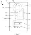
- Figure 1 illustrates a device 100 for indicating violation of a temperature limit of an item according to a preferred embodiment of the invention.
- the device 100 is positionable near the item and includes a sensor 200 configured to change its state permanently when the temperature limit is violated.
- the change in sensor state is machine-readable to provide a permanent indication of the temperature limit violation.
- the sensor 200 includes a reservoir 214 for storing a fluid 202 that changes phase from a solid to a liquid when the temperature limit is violated.
- the sensor 200 also includes a channel 216 in fluid communication with the reservoir 214 for receiving flow of the fluid 202 in liquid phase from the reservoir 214.
- the sensor 200 is arranged to allow flow of the fluid 202 in the liquid phase such that the state of the sensor 200 is permanently changed.
- the sensor 200 is further configured to prevent the fluid flow from permanently changing the sensor state until activation of the sensor 200 from a resting state.
- the device 100 is able to be positioned near the item for providing close thermal contact (not shown).
- the device 100 may be sized and/or shaped for positioning directly at or substantially near the item.
- the device 100 may be compact for placement within the item or directly attached to the item or a container storing the item.
- the device 100 may be sized such that it can be placed within a biological sample or incorporated into a storage container, such as a vial, bag or similar vessel, without causing an appreciable increase in weight or size.
- the device 100 may include a thermally conductive enclosure housing the sensor 200 for providing close thermal contact with the item (not shown).
- the enclosure may include a material having thermally conductive properties selected to be suitable for the particular item and the temperature-controlled storage environment.
- Close thermal contact beneficially ensures that the device 100 relies on the temperature indicated directly at or substantially near the item for accurately indicating temperature limit violations. If the device 100 is not in close thermal contact, a short temperature excursion may result in a false negative indication since the item has not itself experienced a critical rise or drop in temperature. Accordingly, close thermal contact will reduce the likelihood of false negative indications due to the device 100 relying on temperatures that correspond exactly or substantially closely to the actual temperature of the item.
- the sensor 200 includes a supporting layer or substrate 228.
- the supporting layer 228 may be constructed of glass, acrylic, silicon wafer or other flexible polymers, such as polyethylene terephthalate (PET).
- PET polyethylene terephthalate
- the supporting layer 228 is sufficiently thick in order to support additional layers bonded thereon.
- an upper layer 230 is bonded to the supporting layer or substrate 228 and encloses the sensor components.
- the supporting layer 228 may also be treated to be hydrophilic, such as through oxygen plasma etching of the surface. A hydrophilic surface is particularly advantageous for encouraging fluid flow across the supporting layer 228, which is discussed in more detail below.
- the sensor 200 includes a reservoir or fluidic well 214 for storing a fluid 202.
- the fluid 202 may be a single fluid in the form of a solution or a combination of fluids in the form of a mixture.
- the single fluid or combination of fluids 202 are selected to have a desired melting point corresponding to the temperature limit of the item.
- the fluid 202 is an aqueous solution so that properties of the fluid 202 can be varied by dilution, such as the fluid's melting point and freezing point.
- 70% ethanol solution has a melting point at around -50°C
- 100% ethanol has a melting point at around -114°C, so the temperature can be varied by dilution in water.
- Other suitable fluids 202 may include other alcohols such as 1-propanol which has a melting point of -127°C.
- the fluid 202 is initially stored in the reservoir 214 in a liquid state.
- the reservoir 214 is in communication with a channel 216.
- the sensor 200 includes a barrier 224 positioned between the reservoir 214 and the channel 216.
- the barrier 224 may prevent fluid flow from the reservoir 214 from permanently changing the sensor state, the barrier 224 being removable to activate the sensor 200.
- the barrier 224 is illustrated in Figure 1 as a seal, membrane or valve 224 that is positioned between the reservoir 214 and channel 216.
- the barrier 224 may also be provided within the channel 216 or at the end of the channel 216 other than the reservoir end, such as opposite the reservoir 214 that is coupled to the indicator chamber 218. The barrier 224 ensures that fluid leakage to other components of the sensor 200 is not permitted until the sensor 200 adopts an activated state.
- the barrier 224 may be provided in a ventilation path 222 of the sensor 200, as shown in Figures 1 and 2 and described in more detail below.
- the barrier 224 may be positioned between the reservoir or storage chamber 214 and the ventilation path 222, at an end of the ventilation path 222 other than the reservoir end or within the ventilation path 222.
- the barriers in these embodiments prevent flow of the fluid 202 due to back pressure.
- the sensor 200 is then placed in a temperature-controlled environment such that the fluid 202 changes phase from a liquid to a solid.
- the sensor 200 may be placed in a low-temperature environment, such as in a mechanical freezer, so that the fluid 202 freezes at a temperature below its freezing point. Once the liquid freezes and converts to a solid, the sensor 200 adopts a resting state.
- the barrier 224 In order to activate the sensor 200 from the resting state, the barrier 224 must be removed (not shown) so that sensor 200 adopts an activated or armed state. The activation or arming of the sensor 200 may occur through automatic or manual removal of the barrier 224.
- the barrier 224 may be a membrane, seal or valve that blocks a fluid path from the reservoir 214 to the channel 216 and/or ventilation path 222, and may block an opening of the reservoir 214 in fluid communication with the channel 216 and/or ventilation path 222.
- the sensor 200 includes at least one barrier 224 although in some embodiments the sensor 200 may include two or more barriers 224.
- the arming of the sensor 200 may occur through manual removal of the barrier 224, such as by applying or removing an external force on the barrier 224.
- the barrier or membrane 224 may include a magnetic material that traps the fluid 202 in the reservoir 214 in the presence of a magnetic field.
- the barrier or membrane 224 may be constructed of a small ball bearing which becomes trapped in a space between the reservoir 214 and the channel 216.
- the barrier or membrane 224 may be removed by moving the device 100 out of the magnetic field or by turning the magnetic field off.
- the barrier or membrane 224 may be mechanically connected to an external actuator, which applies pressure to the membrane 224 to trap the fluid 202 in the reservoir 214.
- the barrier or membrane 224 may be removed through operation of the external actuator.
- the arming of the sensor 200 may occur through automatic removal of the barrier 224.
- the barrier or membrane 224 may include a temperature-dependent material such as a temperature-dependent shape memory material. When the surrounding temperature reaches a desired temperature, the material may degrade or break open to activate the sensor 200 due to forces exerted by the material at the desired temperature.
- the barrier or membrane 224 may include a temperature-dependent material that shrinks to activate the sensor 200. The material may include a larger thermal expansion coefficient so that when the surrounding temperature reaches a desired temperature, material shrinkage unblocks the fluid path from the reservoir 214 to the channel 216.
- the senor 200 may include a gas-filled capsule, which relies on expansion/contraction of gas (reducing pressure in a sealed capsule), to exert a force.
- the capsule may be constructed by sealing a mixture of two chemicals (e.g. calcium carbonate and acetic acid) which will produce CO 2 gas amongst other components which expand in the capsule.
- the expanded capsule applies force to the barrier or membrane 224 to trap the fluid 202 in the reservoir 214.
- the capsule will shrink which interacts with the barrier or membrane 224 at either end of the channel 16 to remove and activate the sensor 200.
- the capsule can be designed to a trigger the sensor 200 at a specific temperature value or range by varying the mixture and geometry.
- the senor 200 may include a valve-actuated means 224 at one or both ends of the channel 216.
- the valve-actuated means 224 may be a valve that is operable under temperature-dependent conditions. For example, when the surrounding temperature reaches a desired temperature the valve 224 may open, thereby allowing fluid flow into the channel 216.
- the valve 224 may be operable through an external actuator such as a pneumatic pump.
- the device 100 may be positioned near the item for use in indicating temperature limit violations.
- the fluid 202 is selected to have a desired melting point that corresponds exactly with or substantially close to the item's temperature limit, i.e. the critical temperature value or range required to ensure viability. Accordingly, when the item's temperature limit is violated, i.e. the item's temperature exceeds the threshold temperature value or range, the temperature of the fluid 202 exceeds its melting point causing it to melt and change phase from a solid to a liquid. Since the barrier 224 has been removed, the fluid 202 is able to flow in its liquid state from the reservoir 214 and into the channel 216.
- the channel 216 may be sized and shaped such that capillary forces drive the fluid flow from the reservoir 214 and into the channel 216.
- the sensor 200 may be a microfluidic sensor and the channel 216 may be a microfluidic channel that is dimensioned so that capillary forces drive the fluid flow into the channel 216. If the dimensions of the channel 216 are sufficiently small, particularly in terms of height and width, capillary forces will be the dominant factor driving the fluid flow.
- the reservoir 214 may also include a hydrophobic surface to assist in driving fluid flow into the channel 216.
- the reservoir 214 may include a thin layer of TiO 2 coating.
- the channel 216 may also include a hydrophilic surface to assist in driving fluid flow, such as achieved with oxygen plasma etching of the channel's surface.
- the sensor 200 is arranged such that the flow of the fluid 202 causes the state of the sensor 200 to be permanently changed from the activated state to a triggered state.
- the fluid flow causes a permanent change in a property of the sensor 200 that is irreversible such that the sensor 200 cannot revert to the activated state.
- the reservoir 214 incorporates conductors or plates to form an electrical capacitor 204, whereby the presence of a fluid 202 in the fluidic well 214 will alter the dielectric constant of the capacitor 204, hence determining the capacitance value measured in Farads.
- the capacitor 204 may be constructed from interdigitated fingers to maximise the plate surface area and capacitance measured.
- the fluid flow from the reservoir 214 into the channel 216 causes a permanent change in capacitance.
- the fluid flow is driven away from the conductors or plates 206 of the capacitor 204 into the channel 216 and is unable to return to the reservoir 214 to revert the sensor 200 to the activated state.
- the surface of the capacitor's conductors or plates 206 are therefore permanently changed due to the fluid flow.
- the sensor 200 may be configured to measure other electrical or chemical properties of the fluid 202 than capacitance, which is indicative of the triggered state of the sensor 200.
- the permanent change in the sensor property may include an electrical property other than capacitance, such as impedance, resistance and inductance.
- the permanent change in the sensor property may include a chemical property such as density, viscosity and conductivity.
- the sensor 200 includes an indicator chamber 218 at an end of the channel 216 other than the reservoir end, for example, the end of the channel 216 being opposite from the reservoir 214.
- the indicator chamber 218 includes an absorbent material that absorbs the fluid 202. Once this occurs, the fluid 202 is trapped in the absorbent material, thereby preventing the fluid 202 from re-entering the reservoir 214 via the channel 216. Accordingly, the indicator chamber 218 ensures that the sensor 200 cannot be reset and permanently changes its state from the activated state to the triggered state.
- the sensor 200 is also configured to provide a permanent visual indicator of the change in sensor state to the triggered state.
- the absorbent material of the indicator chamber 218 is impregnated with a colour dye that changes colour when the absorbent material is wetted by the fluid flow. Accordingly, the colour change may be observed by a human operator to provide an immediate visual indication of a temperature limit violation.
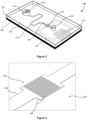
- the indicator chamber 218 is preferably transparent, along with the upper layer 230 of the device 100 as shown in Figure 2 .
- the sensor 200 is optimised to provide a determined time tolerance for indication of the temperature limit violation.
- the time tolerance indicates the length of time, such as in seconds or minutes, that the sensor 200 takes to respond to a temperature limit violation and change its state to the triggered state.
- the time tolerance may be critical depending on the nature of the item. For example, biological samples will typically require a short time tolerance so that a human operator can be quickly alerted to a temperature limit violation. However, the time tolerance may not be so crucial for food products, which may be able to withstand a longer period prior to indication.
- the length and shape of the channel 216 is optimised in conjunction with the volume and type of the fluid 202 to ensure that temperature limit violations are indicated in a timely manner for the particular item.
- the sensor 200 includes a ventilation path 222 for equalising the pressure between the reservoir 214 and the indicator chamber 218.
- the sensor 200 includes a pressure-equalising return path 222 between the reservoir 214 and the indicator chamber 218.
- the return path 222 may include a hydrophobic surface, such as with a thin layer of TiO2 coating, to avoid fluid entry into the return path 222 from the reservoir 214.
- a barrier 224 may also be provided between the return path 222 and reservoir 214 to prevent fluid entry into the return path 222.
- the reservoir 214 and indicator chamber 218 may be vented to atmosphere in order to equalise the pressure as shown in Figure 2 .
- FIG. 2 An alternative embodiment of the device 100 is illustrated in Figure 2 .
- the capacitor 204 is positioned at an end of the channel 216 other than the reservoir or storage chamber end, for example, the end of the channel 216 that is opposite from the reservoir or storage chamber 214, such that the fluid flow is driven towards the conductors 206 of the capacitor 204.
- the fluid 202 melts, the fluid flows from the reservoir 214 into the channel 216 and flows across the conductors 206 of the capacitor 204.
- the presence of the fluid 202 alters the dielectric constant of the capacitor 204, thus causing a permanent change in capacitance.
- the surface of the capacitor 204 is permanently changed due to the fluid flow. If the surrounding temperature falls below the fluid's melting point, the fluid 202 will change phase from a liquid to a solid. Otherwise, it will remain in liquid phase across the capacitor plates 206.
- the sensor 200 of Figure 2 also includes a ventilation path 222 between the reservoir or storage chamber 214 and the capacitor 204.
- the ventilation path 222 is such that the reservoir 214 and capacitor 204 are vented to atmosphere in order to equalise the pressure in the sensor 200 and allow the fluid 202 to flow therethrough.
- the sensor 200 may also include an indicator chamber 218 as described above and the capacitor 204 may be incorporated into the indicator chamber 218. Due to absorption of the fluid 202 by the absorption material of the indicator chamber 216, the fluid 202 will be prevented from returning to the reservoir 214 and reverting the sensor 200 to its activated state.
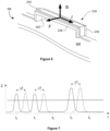
- FIGs 3 and 4 show enlarged views of the capacitor 204 and an inductor 210 of the embodiment of Figure 2 .
- the capacitor 204 is an interdigitated capacitor having two electrodes 206 having fingers and a gap therebetween. The number of fingers and the gap between the fingers determines the capacitance value. The interdigitated fingers advantageously maximise the plate surface area and capacitance measured. The capacitance is tuned to a certain range depending on the fluid type and frequency range of an interrogator 400 (see Figure 5 ).
- the capacitor 204 may be made of metals such as gold, platinum and aluminium.
- the sensor 100 includes an inductor 210 that may be made of the same materials as the capacitor 204.
- the number of turns and distance between the turns of the inductor 210 are selected in order to determine its inductance range.
- An insulating layer 212 of oxide such as silicon dioxide or aluminium oxide is included in the inductor 210 to isolate the contact pads as shown in Figure 4 .
- the sensor 200 includes an electrical circuit 208 connected to the capacitor 204.
- the electrical circuit 208 includes an inductor 210 along with the capacitor 204 to form an electrical tuned resonant circuit.
- the inductor 210 as shown in Figures 1 , 2 and 4 is a wire wound element, and may also include discrete elements as would be conceivable to a skilled addressee for use in the context of the present invention.
- the inductor 210 provides a fixed value of inductance measured in Henrys. As mentioned above, the capacitance will vary due to the fluid flow from the reservoir 214 into the channel 216 when the temperature limit is violated.
- the resonant frequency will vary due to the change in capacitance caused by the fluid flow from the reservoir 214 into the channel 216.
- a variation in resonant frequency of the electrical circuit 208 will provide a permanent indication of a temperature limit violation of the item.
- the resonant frequency and amount of change in frequency due to the temperature limit violation may be adjusted by varying the capacitor 204 and inductor 210 dimensions and/or by adding other components to the electrical circuit 208, such as discrete capacitors and inductors as would be conceivable to a skilled addressee.
- the variation in resonant frequency is machine-readable in order to provide a permanent indication of the temperature limit violation.
- the resonant circuit 208 may be interrogated by direct electrical contact through exposed terminals on a housing of the device 100 (not shown).
- the resonant circuit 208 is interrogated passively and wirelessly by inductive coupling between an interrogator coil 402 and the sensor's inductor coil 210 as described below.
- the variation in resonant frequency may be analysed to not only provide an indication that a temperature limit violation has occurred, but also to indicate the amount of fluid 202 in the sensor 200 that converted to liquid phase and the amount of time that the temperature limit of the item was violated. This may be beneficial where a short temperature excursion has occurred such that only a small amount of the fluid 202 has thawed prior to refreezing. Accordingly, the viability of the item may be assessed depending on the extent of the temperature limit violation.
- An example of a suitable electrical circuit 208 may be derived as follows.
- a printed spiral inductor 210 of 20 turns in a 5 mm diameter produces approximately 5 ⁇ H.
- the device 100 may form part of a system 500, along with an interrogator 400.
- the device 100 may be positioned near the item and the interrogator 400 may be configured to identify the change in sensor state when the temperature limit is violated, and detect violation of the temperature limit based on the identified change in sensor state.
- the interrogator 400 may be used for reading data borne by the sensor circuitry 208 via the inductor coil 210.
- the interrogator 400 may be in the form of a wand that is positionable near the inductor coil 210 of the device 100.
- the interrogator 400 may read data through the inductor coil 210 without removing the device 100 from its temperature-controlled storage environment.
- the interrogator 400 notably includes an interrogator coil 402 and associated interrogator circuitry 404.
- the interrogator circuitry 404 is adapted to generate an excitation signal in the interrogator coil 402. The excitation signal is transferred by induction to the inductor coil 210 of the sensor 200.
- the sensor 200 having the machine-readable indicator draws power from the excitation signal induced in the inductor coil 210, energizing the electrical circuit 208 in the sensor 200.
- the sensor 200 then transmits the data encoded, i.e. the variation in resonant frequency, in the sensory circuitry 208 via the inductor coil 210.
- This data is then captured by the interrogator coil 402 and read by the interrogator circuitry 404.
- the data may be transferred from the interrogator circuitry 404 to a central computer 406 for storage.
- the sensor 200 is further configured to provide a machine-readable identifier of the item so as to provide unique item identification.
- the sensor 200 may include a plurality of resonant members encoding an identification code and the resonant members may have different resonant frequencies from each other.
- the identification code may include information for item identification such as the item number, type, preparation date and expiry date, and information for location identification.
- the item may be identified without the need to remove it from the temperature-controlled storage environment, thereby reducing the likelihood of compromising viability of the item.
- the sensor 200 may include a plurality of micro-mechanical vibratable or resonant members 232 each having a particular resonant frequency, as shown in Figure 6 .
- a common electrical conductor 244 runs along the vibratable members 232.
- the electrical conductor 244 is a section of the electrical circuit 208 of the sensor 200 as shown in Figure 1 including three u-shaped sections corresponding to the resonant members 232.
- the device 100 of Figure 2 may similarly include a plurality of resonant members 232.
- the vibratable members 232 are formed on the supporting layer or substrate 228 of the sensor 200 as shown in Figure 6 .
- the vibratable members 232 are caused to vibrate by an applied excitation or interrogation signal generated by the interrogator 400 that induces an alternating current in the electrical conductor 244 by means of Faraday induction via the inductor coil 210.
- the vibratable members 232 may be vibratable by a Lorentz force.
- the Lorentz force is the force that acts on a charged particle travelling through an orthogonal magnetic field.
- a magnetic field is applied to the vibratable members 232 in a direction perpendicular to the current flow through the electrical conductor 244.
- the device 100 may further include a magnet 104 or element by which a magnetic field is applied orthogonally to the sensor 200.
- a magnet 104 may be positioned adjacent and beneath the sensor 200 in the device 100.
- the magnet 104 may be included in the item or a container storing the item (not shown).
- Figure 6 depicts a vibratable member 232 in the form of a bridge structure 236 including a beam 238 supported by two columns 240 and 242 projecting from a substrate 228.
- the structure shown in Figure 6 may be formed by conventional semiconductor fabrication techniques involving the use of known etching and deposition processes.
- an electrically conductive path 244 is then deposited along the length of the structure 236.
- the electrically conductive path 244 forms part of the electrical circuit 208 as shown in Figure 1 .
- the vibratable members 232 are described in more detail in International Patent Application No. WO 2004/084131 , to the present Applicant.
- alternating electrical current is induced in the inductor coil 210 which thus causes the flow of electrical current through the conductive path 244.
- a force is then applied to the beam 238 in a direction that is orthogonal to both the direction of the current flow and the magnetic field direction. Since the current in the conductor 244 is an alternating current, the orthogonal force generated is also an alternating force, resulting in the vibration of the beam 238. If the frequency of the alternating current in the conductor 244 is at or near the resonant frequency of the beam 238, the beam 238 will vibrate.
- each of the resonant members 232 forming part of the sensor 200 have a notional resonant frequency corresponding to one of a predetermined number of resonant frequencies f 1 , f 2 , f 3 , etc.
- the resonant frequencies f 1 , f 2 , f 3 , etc. are in a different frequency range. If the interrogator 400 detects a resonant frequency at any of the frequency positions f 1 onwards, the interrogator circuitry 404 interprets that resonant frequency as a binary "1". By contrast, the absence of a resonant frequency at any of those predetermined frequency positions is interpreted as a binary "0". The sequence of binary 1's and 0's detected by the interrogator circuitry 404 corresponds to a machine-readable identifier.
- the variation in resonant frequency due to the temperature limit violation may be detected by the interrogator 400 in a similar manner.
- the resonant frequency due to the temperature limit violation is in a different frequency range to the resonant members 232 of the sensor 200.
- the interrogator 400 detects a resonant frequency at e.g. frequency positions f 3 onwards, the interrogator circuitry 404 interprets that resonant frequency as a binary "1", otherwise the absence of a resonant frequency may be interpreted as a binary "0". Further, the interrogator circuitry 404 may discriminate between the sequence corresponding to the machine-readable identifier and the machine-readable indicator through the impedance value.
- the impedance value may be larger for the machine-readable indicator than the machine-readable identifier.
- the machine-readable indicator and machine-readable identifier may advantageously be read in a single interrogation of the electrical circuit 108 by the interrogator 400.
- the interrogator 400 and resonant members 232 are described in greater detail in International Patent Application No. WO 2010/037166 , to the present Applicant.
- the machine-readable identifier may not be incorporated into the substrate 228 of the sensor 200.
- the device 100 may be configured to store a machine-readable tag having the machine-readable identifier.
- the device 100 may be sized to mount with a machine-readable tag for providing the two functions of identification and indication of temperature limit violations of an item.
- the machine-readable tag and sensor 200 are in close proximity for allowing reading of the machine-readable indicator and machine-readable identifier in a single interrogation.
- the machine-readable tag having the machine-readable identifier may be replaced with an active or passive RFID tag which does not necessarily include a MEMS structure, such as a CMOS based RFID tag.
- a resistor having a temperature-dependant value could form part of the tag and that value be read.
- an antenna forming part of the tag may have a temperature-dependant impedance which is detectable by a tune antenna.
- a skilled addressee will be able to conceive of a variety of machine-readable tags which are suitable for use in the context of the present invention.
- the device 100 includes two or more sensors 200 and each sensor 200 stores a different fluid for indicating violation of more than one temperature limit of the item.
- the temperature limit of the item may be a single temperature threshold or a range of temperatures.
- the item may be temperature-sensitive and selected from one of a group including: biological samples; fresh produce, food products, perishables, pharmaceuticals and chemical compounds. Each of these items may require storage at temperatures of -200°C to 0°C. Accordingly, the temperature limit may be either a temperature value or temperature range that is within a range of from -200°C to 0°C.
- the device 100 may be fabricated using MEMS (micro-electromechanical systems) technology, which is also known as PST (Micro System Technology) and micromachining.
- MEMS micro-electromechanical systems
- PST Micro System Technology
- MEMS technology includes fabrication technologies for integrated circuits, and technologies specifically developed for micromachining. It generally relates to the fabrication of components with dimension in the range of micrometres to millimetres.
- MEMS techniques may include for example masking, deposition and etching steps, amongst other well-known lithographic and micromachining processes. It may include for example photolithography and thin film deposition or growth. Typically, the process results in a laminate structure. A number of structural layers can be formed on a substrate, and required components can be formed by selective etching of the substrate and/or sacrificial materials and component materials deposited therein. The resulting micromachined components may be combined with electronics that are fabricated using standard integrated circuit processes.
- the sensor 200 shown in Figures 1 to 4 may be fabricated using standard photolithography methods although the process for forming the sensor 200 of Figures 2 to 4 will now be described.
- the substrate or supporting layer 228 is coated with a photoresist, the thickness of which is determined by its type and rotational speed.
- the photoresist may be SU8 or a polymer such as polydimethylsiloxane (PDMS).
- the substrate is then exposed under an ultraviolet light source with optimal power density.
- the layout of the sensor is applied by a mask developed with computer-aided software, which is usually made of chromium and includes desired patterns.
- An electron beam evaporator is then used to deposit a layer of metals, such as gold, which is evaporated and lifted-off.
- the capacitor 204 and part of the inductor 210 may be deposited in a single step.
- the next step is to create an insulating layer 212 for isolating the contact pads of the inductor 210.
- another photolithography process is performed repeating the steps described above but with a different pattern and change of metal to an oxide, such as silicon dioxide or aluminium oxide.
- a further photolithography process is required to connect the centre of the inductor coil 210 with the inductor pad 212.
- Another photolithography process is required to create the channel 216. The height and width of the channel 216 are controllable when coating the substrate 228 with the photoresist based on the resist type and rotational speed.
- an upper layer or cover 230 is assembled to the substrate 228 to form the reservoir 214 and ventilation path 222.
- the upper layer 230 may be made of acrylic or polyvinyl chloride (PVC) and adhered to the substrate 228.
- the interrogator 400 may be configured to detect a machine-readable indicator of the change in sensor state.
- the interrogator 400 includes an interrogator coil 402.
- the interrogator coil 402 is configured to interrogate an electrical circuit 208 of the sensor 200 (see Figures 1 to 4 ).
- the interrogator coil 402 may be positioned such that it is in proximity to the electrical circuit 208 of the sensor 200 in use. Whilst the interrogator 400 need not be in direct contact with the device 100, it should be positioned in close proximity in order to detect the machine-readable indicator.
- the device 100 is able to be interrogated without requiring removal of the device 100 directly from or near from the item. This advantageously ensures viability of the item since it can remain in a temperature-controlled environment during the interrogation.
- Figure 5 illustrates that the interrogator 400 includes an integrated signal processing circuitry 404 which is able to generate an interrogation signal in the interrogator coil 402.
- an excitation signal is induced in the inductor coil 210 from the interrogation signal in the interrogator coil 402.
- the machine-readable indicator is detected by the interrogator 400 as a variation in resonant frequency of the electrical circuit 208.
- the interrogator 400 may further be configured to detect a machine-readable identifier of the item.
- the machine-readable identifier may include a unique identification code for the item as described herein.
- the identification code may also include information such as the time, date, location of the item and the operator or user.
- the sensor 200 may include at least one resonant member 232 as shown in Figures 1 and 6 .
- the machine-readable identifier may be detected by the interrogator 400 as a variation in resonant frequency of the electrical circuit 208.
- the at least one resonant member 232 may be included on the substrate 228 of the sensor 200 and the common electrical conductor 244 may be part of the electrical circuit 208. Accordingly, the machine-readable identifier and the machine-readable indicator may be detected in a single interrogation of the electrical circuit 208 by the interrogator. The machine-readable identifier and the machine-readable indicator may be distinguished based on the extent of variation of resonant frequency and/or impedance as described above and with reference to Figure 7 .
- the interrogator 400 may emit an alert if a temperature limit violation is detected. This serves to alert an operator if the item's temperature exceeds a critical temperature above or below which the item may become unviable or degrade.
- This alert could be of an auditory, visual or sensory nature, e.g. illumination of an LED, a flashing LED, or a change in colour of an LED, an audible alert such as a tone, or a vibration.
- the system 500 may also include one or more temperature sensors and may be selected from one or more of an optical sensing means including laser and/or infra-red or wired sensing means including thermocouple, thermistor and/or resistance temperature detectors (RTD). It is to be understood that the foregoing examples are not exhaustive and that other suitable means could be envisaged.
- Each temperature sensor may be associated with a single item or more than one item. Where a number of temperature sensors are provided, any variation in temperature across the items can be determined.
- the temperature sensors may advantageously provide instantaneous temperature measurements, in addition to the temperature limit violations indicated and/or detected by the sensor 200.
- the interrogator 400 may further include a communication module for transmitting one or more of: detecting temperature limit violations, identification of the item and temperature of the item.
- the temperature and identification data is recorded and can be downloaded or otherwise electronically transmitted to a remote computer or server either live or at some subsequent time. Accordingly, a permanent data log of the item can be maintained throughout various storage, processing and transport activities that the item may be subject to over its life. The recordings may be made continuously and the data transmitted to a remote computer or server periodically or streamed continuously as required.
- the temperature limit may be either a temperature value or temperature range within a range of from -200°C to 0°C.
- the ite m may be temperature-sensitive and selected from one of a group including: biological samples; fresh produce, food products, perishables, pharmaceuticals and chemical compounds.
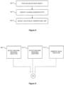
- a flow chart is illustrated showing steps in a method for detecting violation of a temperature limit of an item.
- the method includes at step 300 positioning the inventive device 100 as described herein near the item.
- the method also includes at step 302 identifying the change in sensor state when the temperature limit is violated.
- the method includes at step 304 detecting violation of the temperature limit based on the identified change in sensor state.
- the inventive device 100 is positioned near the item for providing close thermal contact, and may be sized and/or shaped for positioning directly at or substantially near the item.
- the method may include positioning the device 100 within the item, such as a biological sample, or incorporating it into a storage container, such as a vial, bag or similar vessel.
- the method may also include directly attaching the device 100 to the item or a container storing the item.
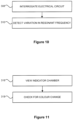
- Figure 9 illustrates a flow chart showing further steps in the method shown in Figure 8 .
- identifying the change in sensor state includes at step 306 detecting a machine-readable indicator of the change in sensor state.
- detecting the machine-readable indicator may include interrogating an electrical circuit 208 of the sensor 200 at step 308 and then detecting a variation in resonant frequency of the electrical circuit 208 at step 310.
- the method may include directly contacting the electrical circuit 208 of the sensor 200 to measure the variation in resonant frequency.
- the method may include positioning an interrogator 400 in the form of a wand near the sensor 200 for passive and wireless interrogation.
- the method may include generating an excitation signal in an interrogator coil 402 of the interrogator 400 and transferring the excitation signal by induction to an inductor coil 210 of the sensor 200.
- the method may include transmitting the data encoding the machine-readable indicator in the sensor circuitry 208 via the inductor coil 210 to the interrogator coil 402.
- the variation in resonant frequency may be detected by the interrogator circuitry 404 reading the data captured by the interrogator coil 402.
- the method may also include transferring the data from the interrogator circuitry 404 to a central computer 406 for storage.
- Figure 9 illustrates that identifying the change in sensor state may also include at step 312 detecting a machine-readable identifier of the item.
- detecting the machine-readable identifier includes interrogating an electrical circuit 208 of the sensor 200 at step 308 and then detecting a variation in resonant frequency of the electrical circuit 208 at step 310.
- the machine-readable identifier can be detected in a similar way to the machine-readable indicator using the interrogator 400 as described above.
- the method may include detecting the machine-readable indicator and machine-readable identifier in a single interrogation of the electrical circuit 208 such as by using interrogator 400.
- the method may also include differentiating between the detected resonant frequencies of the machine-readable indicator and machine-readable identifier based on the frequency value and/or impedance value.
- the step 302 of identifying the change in sensor state also includes at step 314 observing a permanent visual indicator of the change in sensor state as illustrated in Figure 9 .
- observing the visual indicator includes at step 316 viewing an indicator chamber 218 of the sensor 200 having a colour dye and at step 318 checking for a colour change in the dye of the indicator chamber 218.
- viewing of the visual indicator provides for immediate detection by an operator of a temperature limit violation.
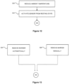
- Figures 12 and 13 illustrate flow charts showing further steps in the method shown in Figure 8 relating to activating the sensor 200.
- the method includes at step 320 reducing the ambient temperature such that a fluid 202 stored in a reservoir 214 of the sensor 200 changes phase from a liquid to a solid.
- the sensor 200 is in a resting state.
- the method may include at step 322 activating the sensor 200 from the resting state to allow the fluid 202 stored in the reservoir 214 to flow into a channel 216 of the sensor 200.
- the step 322 of activating the sensor 200 may include the step of removing a barrier 224 preventing the fluid flow from permanently changing the sensor state.
- the barrier 224 may include one of a seal, a membrane or a valve as described herein.
- the step of removing the barrier 224 may include one or both of at step 324 automatically removing the barrier 224 or at step 326 manually removing the barrier 224.
- the step 324 of automatically removing the barrier 224 may include automatically changing the ambient temperature to a desired temperature such that at least one of: a temperature-dependent material of the barrier 224 degrades or shrinks; and a gas-filled capsule of the sensor 200 contracts to remove a force on the barrier 224.
- the step 326 of manually removing the barrier 224 may include applying and/or removing the presence of a magnetic field influencing a magnetic material of the barrier 224 to alter a magnetic force on the barrier 224; and applying and/or removing a force applied to the barrier 224 by an external actuator coupled to the barrier 224.
- the presence of a magnetic field and the force applied by the external actuator is removed so as to remove forces on the barrier 224.
- the method includes detecting more than one temperature limit violation of an item.
- the device 100 may include two or more sensors 200 with each sensor 200 storing a different fluid 202 for indicating violation of more than one temperature limit of the item. Beneficially, this allows visual and/or machine-readable detection of temperature limit violations to be provided during different stages of thawing of the item.
- the fluid 202 may be a single fluid or combination of fluids selected to have a desired melting point corresponding to the temperature limit of the item.
- the temperature limit may be either a temperature value or temperature range within a range of from -200°C to 0°C.
- the item may be temperature-sensitive and selected from one of a group including: biological samples; fresh produce, food products, perishables, pharmaceuticals and chemical compounds.
- the device provides for permanent indication and detection of temperature limit violations that occur during storage, processing and transportation of temperature-sensitive items, particularly items that require cold, ultra-cold (i.e. less than -60°C) or cryogenic storage.
- the device ensures that a permanent record of temperature limit violations is made due to the permanent change in sensor state, which is machine-readable for processing at a later time.
- the device more accurately and reliability indicates and detects temperature limit violations since they do not rely on human operators to observe indicators or process data records.
- the device provides for visual feedback for immediate detection of temperature limit violations to permit quick intervention by human operators. Further, the device enables machine-readable identification of the item, which may beneficially occur during the same machine interrogation of the device. Since passive and wireless detection of temperature limit violations can be achieved, the device does not require any power or energy source and further is not adversely affected by sterilising gamma radiation. The device is also advantageously sized and shaped so it can readily provide close thermal contact for accurate indication and detection of temperature limit violations.
Landscapes
- Engineering & Computer Science (AREA)
- Mechanical Engineering (AREA)
- Physics & Mathematics (AREA)
- General Physics & Mathematics (AREA)
- Measuring Temperature Or Quantity Of Heat (AREA)
- Sampling And Sample Adjustment (AREA)
Applications Claiming Priority (2)
| Application Number | Priority Date | Filing Date | Title |
|---|---|---|---|
| AU2016903474A AU2016903474A0 (en) | 2016-08-31 | A device, system and method for temperature limit indication and detection of temperature-sensitive items | |
| PCT/AU2017/050933 WO2018039727A1 (en) | 2016-08-31 | 2017-08-31 | A device, system and method for temperature limit indication and detection of temperature-sensitive items |
Publications (3)
| Publication Number | Publication Date |
|---|---|
| EP3507578A1 EP3507578A1 (en) | 2019-07-10 |
| EP3507578A4 EP3507578A4 (en) | 2020-05-06 |
| EP3507578B1 true EP3507578B1 (en) | 2023-05-10 |
Family
ID=61299605
Family Applications (1)
| Application Number | Title | Priority Date | Filing Date |
|---|---|---|---|
| EP17844689.4A Active EP3507578B1 (en) | 2016-08-31 | 2017-08-31 | A device for temperature limit indication and detection of temperature-sensitive items |
Country Status (6)
| Country | Link |
|---|---|
| US (1) | US11467042B2 (enExample) |
| EP (1) | EP3507578B1 (enExample) |
| JP (1) | JP7029442B2 (enExample) |
| CN (1) | CN110192091A (enExample) |
| AU (1) | AU2017320346B2 (enExample) |
| WO (1) | WO2018039727A1 (enExample) |
Families Citing this family (17)
| Publication number | Priority date | Publication date | Assignee | Title |
|---|---|---|---|---|
| JP7204396B2 (ja) * | 2018-09-20 | 2023-01-16 | 株式会社東芝 | 温度閾値センサ、温度閾値検知装置及び温度閾値検知システム |
| JP7154515B2 (ja) | 2018-10-05 | 2022-10-18 | ティーエムアールダブリュ ライフサイエンシーズ,インコーポレイテツド | 極低温条件で生物学的サンプルを保存および同定するための装置 |
| CA3155035C (en) | 2019-10-29 | 2024-06-04 | William Alan BLAIR | Apparatus to facilitate transfer of biological specimens stored at cryogenic conditions |
| IT202000001084A1 (it) * | 2020-01-21 | 2021-07-21 | Enea Agenzia Naz Per Le Nuove Tecnologie Lenergia E Lo Sviluppo Economico Sostenibile | Indicatore di temperatura a risposta impedenziometrica integrabile in sistemi RFID HF in forma di transponder RFID con chip o chipless e metodo di realizzazione di tale indicatore di temperatura. |
| US11817187B2 (en) | 2020-05-18 | 2023-11-14 | TMRW Life Sciences, Inc. | Handling and tracking of biological specimens for cryogenic storage |
| CN112034018B (zh) * | 2020-08-24 | 2021-12-28 | 江南大学 | 基于pdms微流体通道的葡萄糖生物传感器、制备方法及应用 |
| JP7610303B2 (ja) | 2020-09-24 | 2025-01-08 | ティーエムアールダブリュ ライフサイエンシーズ,インコーポレイテツド | 極低温条件で保管された生物学的試料の移送を容易にするためのワークステーション及び装置 |
| US12099890B2 (en) | 2020-10-02 | 2024-09-24 | TMRW Life Sciences, Inc. | Interrogation device and/or system having alignment feature(s) for wireless transponder tagged specimen containers and/or carriers |
| KR102653569B1 (ko) * | 2020-11-16 | 2024-04-03 | 한국화학연구원 | 비가역적 영하용 온도변화 감지형 센서 |
| USD963194S1 (en) | 2020-12-09 | 2022-09-06 | TMRW Life Sciences, Inc. | Cryogenic vial carrier |
| CA3200508A1 (en) | 2020-12-10 | 2022-06-16 | TMRW Life Sciences, Inc. | Specimen holder with wireless transponder for attachment to specimen collection body |
| EP4252009B1 (en) | 2021-01-13 | 2025-03-05 | TMRW Life Sciences, Inc. | System to pick and/or place specimen containers |
| EP4412453A4 (en) | 2021-10-08 | 2025-01-22 | TMRW Life Sciences, Inc. | SYSTEMS, DEVICES AND METHODS FOR TAKING AND/OR PLACING SAMPLE CONTAINERS |
| US12540863B2 (en) * | 2022-07-18 | 2026-02-03 | Zebra Technologies Corporation | Capacitance-based temperature sensor with delay |
| CN116576982B (zh) * | 2023-04-23 | 2026-04-07 | 麦斯塔微电子(深圳)有限公司 | 一种mems测温结构以及测温方法 |
| US20250093214A1 (en) * | 2023-09-18 | 2025-03-20 | Temptime Corporation | Use of encapsulated polar protic chemistries for rfid temperature monitoring |
| WO2025155520A1 (en) * | 2024-01-19 | 2025-07-24 | Hid Global Corp. | Temperature sensitive interdigital sensor |
Family Cites Families (21)
| Publication number | Priority date | Publication date | Assignee | Title |
|---|---|---|---|---|
| US3695903A (en) | 1970-05-04 | 1972-10-03 | American Standard Inc | Time/temperature indicators |
| JPS59164929A (ja) | 1983-03-11 | 1984-09-18 | Mishima Seishi Kk | 不可逆温度センサ− |
| FR2684446B1 (fr) * | 1991-12-03 | 1996-02-02 | Cool Sarl | Indicateur de conservation pour produits congeles ou refrigeres et procede de mise en óoeuvre de cet indicateur. |
| IT1254353B (it) | 1992-05-07 | 1995-09-14 | Consiglio Nazionale Ricerche | Dispositivo indicatore di storia termica in particolare per prodotti surgelati e simili. |
| US6848390B2 (en) | 1999-04-28 | 2005-02-01 | Jeffrey W. Akers | Shape memory thermal exposure monitor |
| AU2003241283A1 (en) * | 2002-04-03 | 2003-10-20 | 3M Innovative Properties Company | Time or time-temperature indicating articles |
| AU2003901240A0 (en) | 2003-03-17 | 2003-04-03 | Zip Holdings Pty Ltd | Memory devices |
| ATE554183T1 (de) | 2003-09-17 | 2012-05-15 | Cryolog S A | Verfahren und vorrichtung zur bestimmung, ob ein produkt zur verwendung oder zum verbrauch geeignet ist |
| US7275863B1 (en) * | 2003-12-04 | 2007-10-02 | Time Temperature Integration, Inc. | Threshold calorimeter/shelf life monitor |
| US7940605B2 (en) * | 2005-04-29 | 2011-05-10 | Prasidiux, Llc | Stimulus indicating device employing polymer gels |
| JP2008544280A (ja) * | 2005-06-21 | 2008-12-04 | コーナーストーン リサーチ グループ,インコーポレーテッド | 形状記憶ポリマを使用する環境条件累積追跡積分センサ |
| JP4957089B2 (ja) * | 2006-06-13 | 2012-06-20 | 富士ゼロックス株式会社 | センサ |
| JP2008164587A (ja) * | 2006-12-06 | 2008-07-17 | Canon Inc | 温度センサ付共振タグ |
| GB0718816D0 (en) * | 2007-09-26 | 2007-11-07 | Intray Ltd | Time indicator device |
| EP2335182B1 (en) | 2008-10-03 | 2015-10-28 | Bluechiip Pty Ltd | Ringup/ ringdown interrogation of rfid tags |
| NO331993B1 (no) * | 2011-04-15 | 2012-05-21 | Keep It Technologies As | Tid-temperatur indikatorsystem |
| WO2014210460A1 (en) * | 2013-06-28 | 2014-12-31 | Jp Laboratories, Inc. | Time indicating devices based on counterbalancing reactions |
| JP5723474B1 (ja) * | 2014-09-02 | 2015-05-27 | 日油技研工業株式会社 | 温度管理材 |
| CN105136330B (zh) * | 2015-07-29 | 2019-10-15 | 深圳九星印刷包装集团有限公司 | 时间温度指示装置及其制造方法 |
| US10908031B1 (en) * | 2015-10-16 | 2021-02-02 | Prasidiux, Llc | Stimulus indicating device employing the swelling action of polymer gels |
| CN105758551A (zh) | 2016-02-25 | 2016-07-13 | 深圳九星印刷包装集团有限公司 | 时间温度指示装置 |
-
2017
- 2017-08-31 AU AU2017320346A patent/AU2017320346B2/en not_active Ceased
- 2017-08-31 JP JP2019510703A patent/JP7029442B2/ja not_active Expired - Fee Related
- 2017-08-31 WO PCT/AU2017/050933 patent/WO2018039727A1/en not_active Ceased
- 2017-08-31 CN CN201780066433.9A patent/CN110192091A/zh active Pending
- 2017-08-31 EP EP17844689.4A patent/EP3507578B1/en active Active
- 2017-08-31 US US16/328,807 patent/US11467042B2/en active Active
Also Published As
| Publication number | Publication date |
|---|---|
| AU2017320346A1 (en) | 2019-04-18 |
| AU2017320346B2 (en) | 2022-09-15 |
| WO2018039727A1 (en) | 2018-03-08 |
| US11467042B2 (en) | 2022-10-11 |
| JP7029442B2 (ja) | 2022-03-03 |
| EP3507578A4 (en) | 2020-05-06 |
| CN110192091A (zh) | 2019-08-30 |
| JP2019526797A (ja) | 2019-09-19 |
| EP3507578A1 (en) | 2019-07-10 |
| US20190212210A1 (en) | 2019-07-11 |
Similar Documents
| Publication | Publication Date | Title |
|---|---|---|
| EP3507578B1 (en) | A device for temperature limit indication and detection of temperature-sensitive items | |
| US10722623B2 (en) | Smart bag used in sensing physiological and/or physical parameters of bags containing biological substance | |
| JP4851465B2 (ja) | 時間温度指示装置 | |
| EP1155288B1 (en) | System, device and method for reporting a physical or chemical event or state | |
| US6617963B1 (en) | Event-recording devices with identification codes | |
| US20060152313A1 (en) | Temperature sensing devices, systems and methods | |
| US9626612B2 (en) | Radio frequency identification sensor assembly | |
| KR20070065420A (ko) | 마이크로-구조화된 시간 의존형 지시기 | |
| KR20040073476A (ko) | 부패하기 쉬운 상품을 위한 환경 파라미터 지시자 | |
| US6182514B1 (en) | Pressure sensor for sealed containers | |
| WO2025184579A1 (en) | Sensors for cold chain monitoring based on movement | |
| JP7579854B2 (ja) | 試料管用のマイクロシステムラベル | |
| Schmitt et al. | Design, fabrication and characterisation of a microfluidic time-temperature indicator | |
| SI25095A (sl) | Temperaturni indikator za indikacijo nihanja temperature artiklov nad predpisano mejo v hladni verigi | |
| CN119256214A (zh) | 温度指示器 | |
| US20250329242A1 (en) | Field armable environmental sensor device | |
| Watters et al. | Wireless event-recording device with identification codes |
Legal Events
| Date | Code | Title | Description |
|---|---|---|---|
| STAA | Information on the status of an ep patent application or granted ep patent |
Free format text: STATUS: THE INTERNATIONAL PUBLICATION HAS BEEN MADE |
|
| PUAI | Public reference made under article 153(3) epc to a published international application that has entered the european phase |
Free format text: ORIGINAL CODE: 0009012 |
|
| STAA | Information on the status of an ep patent application or granted ep patent |
Free format text: STATUS: REQUEST FOR EXAMINATION WAS MADE |
|
| 17P | Request for examination filed |
Effective date: 20190320 |
|
| AK | Designated contracting states |
Kind code of ref document: A1 Designated state(s): AL AT BE BG CH CY CZ DE DK EE ES FI FR GB GR HR HU IE IS IT LI LT LU LV MC MK MT NL NO PL PT RO RS SE SI SK SM TR |
|
| AX | Request for extension of the european patent |
Extension state: BA ME |
|
| DAV | Request for validation of the european patent (deleted) | ||
| DAX | Request for extension of the european patent (deleted) | ||
| A4 | Supplementary search report drawn up and despatched |
Effective date: 20200402 |
|
| RIC1 | Information provided on ipc code assigned before grant |
Ipc: G01K 3/04 20060101AFI20200328BHEP Ipc: B65D 79/02 20060101ALI20200328BHEP Ipc: G01K 11/06 20060101ALI20200328BHEP |
|
| STAA | Information on the status of an ep patent application or granted ep patent |
Free format text: STATUS: EXAMINATION IS IN PROGRESS |
|
| 17Q | First examination report despatched |
Effective date: 20210222 |
|
| GRAP | Despatch of communication of intention to grant a patent |
Free format text: ORIGINAL CODE: EPIDOSNIGR1 |
|
| STAA | Information on the status of an ep patent application or granted ep patent |
Free format text: STATUS: GRANT OF PATENT IS INTENDED |
|
| INTG | Intention to grant announced |
Effective date: 20221124 |
|
| GRAS | Grant fee paid |
Free format text: ORIGINAL CODE: EPIDOSNIGR3 |
|
| GRAA | (expected) grant |
Free format text: ORIGINAL CODE: 0009210 |
|
| STAA | Information on the status of an ep patent application or granted ep patent |
Free format text: STATUS: THE PATENT HAS BEEN GRANTED |
|
| AK | Designated contracting states |
Kind code of ref document: B1 Designated state(s): AL AT BE BG CH CY CZ DE DK EE ES FI FR GB GR HR HU IE IS IT LI LT LU LV MC MK MT NL NO PL PT RO RS SE SI SK SM TR |
|
| REG | Reference to a national code |
Ref country code: GB Ref legal event code: FG4D |
|
| REG | Reference to a national code |
Ref country code: AT Ref legal event code: REF Ref document number: 1567112 Country of ref document: AT Kind code of ref document: T Effective date: 20230515 Ref country code: CH Ref legal event code: EP |
|
| REG | Reference to a national code |
Ref country code: DE Ref legal event code: R096 Ref document number: 602017068703 Country of ref document: DE |
|
| REG | Reference to a national code |
Ref country code: IE Ref legal event code: FG4D |
|
| P01 | Opt-out of the competence of the unified patent court (upc) registered |
Effective date: 20230527 |
|
| REG | Reference to a national code |
Ref country code: LT Ref legal event code: MG9D |
|
| REG | Reference to a national code |
Ref country code: NL Ref legal event code: MP Effective date: 20230510 |
|
| REG | Reference to a national code |
Ref country code: AT Ref legal event code: MK05 Ref document number: 1567112 Country of ref document: AT Kind code of ref document: T Effective date: 20230510 |
|
| PG25 | Lapsed in a contracting state [announced via postgrant information from national office to epo] |
Ref country code: SE Free format text: LAPSE BECAUSE OF FAILURE TO SUBMIT A TRANSLATION OF THE DESCRIPTION OR TO PAY THE FEE WITHIN THE PRESCRIBED TIME-LIMIT Effective date: 20230510 Ref country code: PT Free format text: LAPSE BECAUSE OF FAILURE TO SUBMIT A TRANSLATION OF THE DESCRIPTION OR TO PAY THE FEE WITHIN THE PRESCRIBED TIME-LIMIT Effective date: 20230911 Ref country code: NO Free format text: LAPSE BECAUSE OF FAILURE TO SUBMIT A TRANSLATION OF THE DESCRIPTION OR TO PAY THE FEE WITHIN THE PRESCRIBED TIME-LIMIT Effective date: 20230810 Ref country code: NL Free format text: LAPSE BECAUSE OF FAILURE TO SUBMIT A TRANSLATION OF THE DESCRIPTION OR TO PAY THE FEE WITHIN THE PRESCRIBED TIME-LIMIT Effective date: 20230510 Ref country code: ES Free format text: LAPSE BECAUSE OF FAILURE TO SUBMIT A TRANSLATION OF THE DESCRIPTION OR TO PAY THE FEE WITHIN THE PRESCRIBED TIME-LIMIT Effective date: 20230510 Ref country code: AT Free format text: LAPSE BECAUSE OF FAILURE TO SUBMIT A TRANSLATION OF THE DESCRIPTION OR TO PAY THE FEE WITHIN THE PRESCRIBED TIME-LIMIT Effective date: 20230510 |
|
| PGFP | Annual fee paid to national office [announced via postgrant information from national office to epo] |
Ref country code: IT Payment date: 20230816 Year of fee payment: 7 Ref country code: GB Payment date: 20230816 Year of fee payment: 7 Ref country code: CH Payment date: 20230902 Year of fee payment: 7 |
|
| PG25 | Lapsed in a contracting state [announced via postgrant information from national office to epo] |
Ref country code: RS Free format text: LAPSE BECAUSE OF FAILURE TO SUBMIT A TRANSLATION OF THE DESCRIPTION OR TO PAY THE FEE WITHIN THE PRESCRIBED TIME-LIMIT Effective date: 20230510 Ref country code: PL Free format text: LAPSE BECAUSE OF FAILURE TO SUBMIT A TRANSLATION OF THE DESCRIPTION OR TO PAY THE FEE WITHIN THE PRESCRIBED TIME-LIMIT Effective date: 20230510 Ref country code: LV Free format text: LAPSE BECAUSE OF FAILURE TO SUBMIT A TRANSLATION OF THE DESCRIPTION OR TO PAY THE FEE WITHIN THE PRESCRIBED TIME-LIMIT Effective date: 20230510 Ref country code: LT Free format text: LAPSE BECAUSE OF FAILURE TO SUBMIT A TRANSLATION OF THE DESCRIPTION OR TO PAY THE FEE WITHIN THE PRESCRIBED TIME-LIMIT Effective date: 20230510 Ref country code: IS Free format text: LAPSE BECAUSE OF FAILURE TO SUBMIT A TRANSLATION OF THE DESCRIPTION OR TO PAY THE FEE WITHIN THE PRESCRIBED TIME-LIMIT Effective date: 20230910 Ref country code: HR Free format text: LAPSE BECAUSE OF FAILURE TO SUBMIT A TRANSLATION OF THE DESCRIPTION OR TO PAY THE FEE WITHIN THE PRESCRIBED TIME-LIMIT Effective date: 20230510 Ref country code: GR Free format text: LAPSE BECAUSE OF FAILURE TO SUBMIT A TRANSLATION OF THE DESCRIPTION OR TO PAY THE FEE WITHIN THE PRESCRIBED TIME-LIMIT Effective date: 20230811 |
|
| PGFP | Annual fee paid to national office [announced via postgrant information from national office to epo] |
Ref country code: FR Payment date: 20230825 Year of fee payment: 7 Ref country code: DE Payment date: 20230831 Year of fee payment: 7 |
|
| PG25 | Lapsed in a contracting state [announced via postgrant information from national office to epo] |
Ref country code: FI Free format text: LAPSE BECAUSE OF FAILURE TO SUBMIT A TRANSLATION OF THE DESCRIPTION OR TO PAY THE FEE WITHIN THE PRESCRIBED TIME-LIMIT Effective date: 20230510 |
|
| PG25 | Lapsed in a contracting state [announced via postgrant information from national office to epo] |
Ref country code: SK Free format text: LAPSE BECAUSE OF FAILURE TO SUBMIT A TRANSLATION OF THE DESCRIPTION OR TO PAY THE FEE WITHIN THE PRESCRIBED TIME-LIMIT Effective date: 20230510 |
|
| PG25 | Lapsed in a contracting state [announced via postgrant information from national office to epo] |
Ref country code: SM Free format text: LAPSE BECAUSE OF FAILURE TO SUBMIT A TRANSLATION OF THE DESCRIPTION OR TO PAY THE FEE WITHIN THE PRESCRIBED TIME-LIMIT Effective date: 20230510 Ref country code: SK Free format text: LAPSE BECAUSE OF FAILURE TO SUBMIT A TRANSLATION OF THE DESCRIPTION OR TO PAY THE FEE WITHIN THE PRESCRIBED TIME-LIMIT Effective date: 20230510 Ref country code: RO Free format text: LAPSE BECAUSE OF FAILURE TO SUBMIT A TRANSLATION OF THE DESCRIPTION OR TO PAY THE FEE WITHIN THE PRESCRIBED TIME-LIMIT Effective date: 20230510 Ref country code: EE Free format text: LAPSE BECAUSE OF FAILURE TO SUBMIT A TRANSLATION OF THE DESCRIPTION OR TO PAY THE FEE WITHIN THE PRESCRIBED TIME-LIMIT Effective date: 20230510 Ref country code: DK Free format text: LAPSE BECAUSE OF FAILURE TO SUBMIT A TRANSLATION OF THE DESCRIPTION OR TO PAY THE FEE WITHIN THE PRESCRIBED TIME-LIMIT Effective date: 20230510 Ref country code: CZ Free format text: LAPSE BECAUSE OF FAILURE TO SUBMIT A TRANSLATION OF THE DESCRIPTION OR TO PAY THE FEE WITHIN THE PRESCRIBED TIME-LIMIT Effective date: 20230510 |
|
| REG | Reference to a national code |
Ref country code: DE Ref legal event code: R097 Ref document number: 602017068703 Country of ref document: DE |
|
| PG25 | Lapsed in a contracting state [announced via postgrant information from national office to epo] |
Ref country code: MC Free format text: LAPSE BECAUSE OF FAILURE TO SUBMIT A TRANSLATION OF THE DESCRIPTION OR TO PAY THE FEE WITHIN THE PRESCRIBED TIME-LIMIT Effective date: 20230510 |
|
| PLBE | No opposition filed within time limit |
Free format text: ORIGINAL CODE: 0009261 |
|
| STAA | Information on the status of an ep patent application or granted ep patent |
Free format text: STATUS: NO OPPOSITION FILED WITHIN TIME LIMIT |
|
| PG25 | Lapsed in a contracting state [announced via postgrant information from national office to epo] |
Ref country code: MC Free format text: LAPSE BECAUSE OF FAILURE TO SUBMIT A TRANSLATION OF THE DESCRIPTION OR TO PAY THE FEE WITHIN THE PRESCRIBED TIME-LIMIT Effective date: 20230510 |
|
| PG25 | Lapsed in a contracting state [announced via postgrant information from national office to epo] |
Ref country code: LU Free format text: LAPSE BECAUSE OF NON-PAYMENT OF DUE FEES Effective date: 20230831 |
|
| 26N | No opposition filed |
Effective date: 20240213 |
|
| PG25 | Lapsed in a contracting state [announced via postgrant information from national office to epo] |
Ref country code: LU Free format text: LAPSE BECAUSE OF NON-PAYMENT OF DUE FEES Effective date: 20230831 |
|
| PG25 | Lapsed in a contracting state [announced via postgrant information from national office to epo] |
Ref country code: SI Free format text: LAPSE BECAUSE OF FAILURE TO SUBMIT A TRANSLATION OF THE DESCRIPTION OR TO PAY THE FEE WITHIN THE PRESCRIBED TIME-LIMIT Effective date: 20230510 |
|
| REG | Reference to a national code |
Ref country code: BE Ref legal event code: MM Effective date: 20230831 |
|
| REG | Reference to a national code |
Ref country code: IE Ref legal event code: MM4A |
|
| PG25 | Lapsed in a contracting state [announced via postgrant information from national office to epo] |
Ref country code: SI Free format text: LAPSE BECAUSE OF FAILURE TO SUBMIT A TRANSLATION OF THE DESCRIPTION OR TO PAY THE FEE WITHIN THE PRESCRIBED TIME-LIMIT Effective date: 20230510 |
|
| PG25 | Lapsed in a contracting state [announced via postgrant information from national office to epo] |
Ref country code: IE Free format text: LAPSE BECAUSE OF NON-PAYMENT OF DUE FEES Effective date: 20230831 |
|
| PG25 | Lapsed in a contracting state [announced via postgrant information from national office to epo] |
Ref country code: IE Free format text: LAPSE BECAUSE OF NON-PAYMENT OF DUE FEES Effective date: 20230831 |
|
| PG25 | Lapsed in a contracting state [announced via postgrant information from national office to epo] |
Ref country code: BE Free format text: LAPSE BECAUSE OF NON-PAYMENT OF DUE FEES Effective date: 20230831 |
|
| PG25 | Lapsed in a contracting state [announced via postgrant information from national office to epo] |
Ref country code: BG Free format text: LAPSE BECAUSE OF FAILURE TO SUBMIT A TRANSLATION OF THE DESCRIPTION OR TO PAY THE FEE WITHIN THE PRESCRIBED TIME-LIMIT Effective date: 20230510 |
|
| PG25 | Lapsed in a contracting state [announced via postgrant information from national office to epo] |
Ref country code: BG Free format text: LAPSE BECAUSE OF FAILURE TO SUBMIT A TRANSLATION OF THE DESCRIPTION OR TO PAY THE FEE WITHIN THE PRESCRIBED TIME-LIMIT Effective date: 20230510 |
|
| REG | Reference to a national code |
Ref country code: DE Ref legal event code: R119 Ref document number: 602017068703 Country of ref document: DE |
|
| REG | Reference to a national code |
Ref country code: CH Ref legal event code: PL |
|
| GBPC | Gb: european patent ceased through non-payment of renewal fee |
Effective date: 20240831 |
|
| PG25 | Lapsed in a contracting state [announced via postgrant information from national office to epo] |
Ref country code: CH Free format text: LAPSE BECAUSE OF NON-PAYMENT OF DUE FEES Effective date: 20240831 |
|
| PG25 | Lapsed in a contracting state [announced via postgrant information from national office to epo] |
Ref country code: DE Free format text: LAPSE BECAUSE OF NON-PAYMENT OF DUE FEES Effective date: 20250301 |
|
| PG25 | Lapsed in a contracting state [announced via postgrant information from national office to epo] |
Ref country code: GB Free format text: LAPSE BECAUSE OF NON-PAYMENT OF DUE FEES Effective date: 20240831 |
|
| PG25 | Lapsed in a contracting state [announced via postgrant information from national office to epo] |
Ref country code: IT Free format text: LAPSE BECAUSE OF NON-PAYMENT OF DUE FEES Effective date: 20240831 |
|
| PG25 | Lapsed in a contracting state [announced via postgrant information from national office to epo] |
Ref country code: FR Free format text: LAPSE BECAUSE OF NON-PAYMENT OF DUE FEES Effective date: 20240831 |
|
| PG25 | Lapsed in a contracting state [announced via postgrant information from national office to epo] |
Ref country code: CY Free format text: LAPSE BECAUSE OF FAILURE TO SUBMIT A TRANSLATION OF THE DESCRIPTION OR TO PAY THE FEE WITHIN THE PRESCRIBED TIME-LIMIT; INVALID AB INITIO Effective date: 20170831 |
|
| PG25 | Lapsed in a contracting state [announced via postgrant information from national office to epo] |
Ref country code: HU Free format text: LAPSE BECAUSE OF FAILURE TO SUBMIT A TRANSLATION OF THE DESCRIPTION OR TO PAY THE FEE WITHIN THE PRESCRIBED TIME-LIMIT; INVALID AB INITIO Effective date: 20170831 |
|
| PG25 | Lapsed in a contracting state [announced via postgrant information from national office to epo] |
Ref country code: TR Free format text: LAPSE BECAUSE OF FAILURE TO SUBMIT A TRANSLATION OF THE DESCRIPTION OR TO PAY THE FEE WITHIN THE PRESCRIBED TIME-LIMIT Effective date: 20230510 |