EP3507480B1 - Mediumleitung einer brennkraftmaschine - Google Patents
Mediumleitung einer brennkraftmaschine Download PDFInfo
- Publication number
- EP3507480B1 EP3507480B1 EP17764339.2A EP17764339A EP3507480B1 EP 3507480 B1 EP3507480 B1 EP 3507480B1 EP 17764339 A EP17764339 A EP 17764339A EP 3507480 B1 EP3507480 B1 EP 3507480B1
- Authority
- EP
- European Patent Office
- Prior art keywords
- main body
- medium line
- blow
- vibrations
- medium
- Prior art date
- Legal status (The legal status is an assumption and is not a legal conclusion. Google has not performed a legal analysis and makes no representation as to the accuracy of the status listed.)
- Active
Links
Images

Classifications
-
- F—MECHANICAL ENGINEERING; LIGHTING; HEATING; WEAPONS; BLASTING
- F02—COMBUSTION ENGINES; HOT-GAS OR COMBUSTION-PRODUCT ENGINE PLANTS
- F02M—SUPPLYING COMBUSTION ENGINES IN GENERAL WITH COMBUSTIBLE MIXTURES OR CONSTITUENTS THEREOF
- F02M27/00—Apparatus for treating combustion-air, fuel, or fuel-air mixture, by catalysts, electric means, magnetism, rays, sound waves, or the like
- F02M27/08—Apparatus for treating combustion-air, fuel, or fuel-air mixture, by catalysts, electric means, magnetism, rays, sound waves, or the like by sonic or ultrasonic waves
-
- B—PERFORMING OPERATIONS; TRANSPORTING
- B06—GENERATING OR TRANSMITTING MECHANICAL VIBRATIONS IN GENERAL
- B06B—METHODS OR APPARATUS FOR GENERATING OR TRANSMITTING MECHANICAL VIBRATIONS OF INFRASONIC, SONIC, OR ULTRASONIC FREQUENCY, e.g. FOR PERFORMING MECHANICAL WORK IN GENERAL
- B06B1/00—Methods or apparatus for generating mechanical vibrations of infrasonic, sonic, or ultrasonic frequency
- B06B1/02—Methods or apparatus for generating mechanical vibrations of infrasonic, sonic, or ultrasonic frequency making use of electrical energy
- B06B1/06—Methods or apparatus for generating mechanical vibrations of infrasonic, sonic, or ultrasonic frequency making use of electrical energy operating with piezoelectric effect or with electrostriction
-
- B—PERFORMING OPERATIONS; TRANSPORTING
- B06—GENERATING OR TRANSMITTING MECHANICAL VIBRATIONS IN GENERAL
- B06B—METHODS OR APPARATUS FOR GENERATING OR TRANSMITTING MECHANICAL VIBRATIONS OF INFRASONIC, SONIC, OR ULTRASONIC FREQUENCY, e.g. FOR PERFORMING MECHANICAL WORK IN GENERAL
- B06B1/00—Methods or apparatus for generating mechanical vibrations of infrasonic, sonic, or ultrasonic frequency
- B06B1/10—Methods or apparatus for generating mechanical vibrations of infrasonic, sonic, or ultrasonic frequency making use of mechanical energy
- B06B1/16—Methods or apparatus for generating mechanical vibrations of infrasonic, sonic, or ultrasonic frequency making use of mechanical energy operating with systems involving rotary unbalanced masses
-
- F—MECHANICAL ENGINEERING; LIGHTING; HEATING; WEAPONS; BLASTING
- F02—COMBUSTION ENGINES; HOT-GAS OR COMBUSTION-PRODUCT ENGINE PLANTS
- F02M—SUPPLYING COMBUSTION ENGINES IN GENERAL WITH COMBUSTIBLE MIXTURES OR CONSTITUENTS THEREOF
- F02M25/00—Engine-pertinent apparatus for adding non-fuel substances or small quantities of secondary fuel to combustion-air, main fuel or fuel-air mixture
- F02M25/06—Engine-pertinent apparatus for adding non-fuel substances or small quantities of secondary fuel to combustion-air, main fuel or fuel-air mixture adding lubricant vapours
-
- F—MECHANICAL ENGINEERING; LIGHTING; HEATING; WEAPONS; BLASTING
- F02—COMBUSTION ENGINES; HOT-GAS OR COMBUSTION-PRODUCT ENGINE PLANTS
- F02M—SUPPLYING COMBUSTION ENGINES IN GENERAL WITH COMBUSTIBLE MIXTURES OR CONSTITUENTS THEREOF
- F02M35/00—Combustion-air cleaners, air intakes, intake silencers, or induction systems specially adapted for, or arranged on, internal-combustion engines
- F02M35/02—Air cleaners
- F02M35/08—Air cleaners with means for removing dust, particles or liquids from cleaners; with means for indicating clogging; with by-pass means; Regeneration of cleaners
- F02M35/088—Water, snow or ice proofing; Separation or drainage of water, snow or ice
-
- F—MECHANICAL ENGINEERING; LIGHTING; HEATING; WEAPONS; BLASTING
- F02—COMBUSTION ENGINES; HOT-GAS OR COMBUSTION-PRODUCT ENGINE PLANTS
- F02M—SUPPLYING COMBUSTION ENGINES IN GENERAL WITH COMBUSTIBLE MIXTURES OR CONSTITUENTS THEREOF
- F02M35/00—Combustion-air cleaners, air intakes, intake silencers, or induction systems specially adapted for, or arranged on, internal-combustion engines
- F02M35/10—Air intakes; Induction systems
- F02M35/10209—Fluid connections to the air intake system; their arrangement of pipes, valves or the like
- F02M35/10222—Exhaust gas recirculation [EGR]; Positive crankcase ventilation [PCV]; Additional air admission, lubricant or fuel vapour admission
-
- F—MECHANICAL ENGINEERING; LIGHTING; HEATING; WEAPONS; BLASTING
- F02—COMBUSTION ENGINES; HOT-GAS OR COMBUSTION-PRODUCT ENGINE PLANTS
- F02M—SUPPLYING COMBUSTION ENGINES IN GENERAL WITH COMBUSTIBLE MIXTURES OR CONSTITUENTS THEREOF
- F02M35/00—Combustion-air cleaners, air intakes, intake silencers, or induction systems specially adapted for, or arranged on, internal-combustion engines
- F02M35/10—Air intakes; Induction systems
- F02M35/10242—Devices or means connected to or integrated into air intakes; Air intakes combined with other engine or vehicle parts
-
- Y—GENERAL TAGGING OF NEW TECHNOLOGICAL DEVELOPMENTS; GENERAL TAGGING OF CROSS-SECTIONAL TECHNOLOGIES SPANNING OVER SEVERAL SECTIONS OF THE IPC; TECHNICAL SUBJECTS COVERED BY FORMER USPC CROSS-REFERENCE ART COLLECTIONS [XRACs] AND DIGESTS
- Y02—TECHNOLOGIES OR APPLICATIONS FOR MITIGATION OR ADAPTATION AGAINST CLIMATE CHANGE
- Y02T—CLIMATE CHANGE MITIGATION TECHNOLOGIES RELATED TO TRANSPORTATION
- Y02T10/00—Road transport of goods or passengers
- Y02T10/10—Internal combustion engine [ICE] based vehicles
- Y02T10/12—Improving ICE efficiencies
Definitions
- the invention relates to a medium line of an internal combustion engine according to the preamble of claim 1, in particular for blow-by gases and/or intake air of internal combustion engines.
- This can in particular be internal combustion engines that are used in motor vehicles or motor vehicles with such internal combustion engines.
- ice can form within the medium lines of an internal combustion engine. This particularly affects medium lines for blow-by gases or fresh air in the intake tract of an internal combustion engine. If larger ice elements form on the peripheral walls of the medium line, which are released by heating during operation of the internal combustion engine and are moved along by the medium guided through the medium line, such ice elements can damage the internal combustion engine, in particular a compressor wheel of a turbocharger that is arranged downstream of the medium line.
- a medium line for passing a medium within which a vibration element is arranged.
- This is a passive vibration element that is driven by the flow of the medium and is intended to protect the medium line from icing - without the supply of external energy.
- Flexible ring membranes and cilia are proposed as vibration elements, which are intended to be set into vibration by the medium flow.
- the medium line is intended for a crankcase ventilation line.
- a combination of a body and a generator for generating an alternating electromagnetic field is known.
- the body of this combination has at least one heating zone made of a plastic with ferrite additives that is heated by exposure to the alternating field of the generator.
- the invention is based on the object of providing a medium line of an internal combustion engine according to the preamble of claim 1, which can be produced inexpensively and easily assembled and reliably reduces or completely prevents the accumulation of ice.
- a medium line of an internal combustion engine comprises a base body and at least one flow region delimited by a peripheral wall of the base body and a blow-by gas introduction point.
- the flow region is intended for a medium to flow through, in particular for passing through a medium, such as for passing through blow-by gases and/or fresh air.
- At least one means for exciting vibrations of the base body is arranged on the base body outside the flow region in the area of the blow-by gas introduction point, which means enables smaller ice elements to be mechanically released.
- the at least one means for exciting vibrations is arranged in the area of the blow-by gas introduction point on the outside of an intake scoop, viewed in the direction of flow, and on a side opposite the blow-by gas introduction point on the outside of the base body of the medium line.
- the term "means for inducing vibrations” refers to any means for inducing vibrations that are suitable for causing the base body to vibrate from the outside. Such means can also be referred to as shakers.
- the external introduction of the excitation of the base body has the advantage that the formation of ice layers can be effectively counteracted or the formation of thicker ice layers can be avoided by the fact that the smallest ice particles that form on the inner peripheral wall are detached by the vibrations and - harmless to the internal combustion engine - are carried away by the flow of the medium and carried away.
- the arrangement of the at least one means for stimulating vibrations on the outside of the base body has the further advantage that the fixing and assembly can be implemented using simple and cost-effective concepts.
- the implementation of a medium line according to the invention is thus possible regardless of the internal geometric complexity of the medium line, i.e. in particular regardless of the geometry and complexity of the medium line in the area of the inner peripheral wall.
- Medium lines according to the invention can also be achieved without great effort by retrofitting existing medium lines if the corresponding installation space is available.
- the at least one means for exciting vibrations is arranged in the area of the blow-by gas introduction point on the outside of an intake scoop, viewed in the direction of flow, and on a side opposite the blow-by gas introduction point on the outside of the base body of the medium line, preferably on the opposite side and - viewed in the main flow direction - at the level of the blow-by gas introduction point and/or slightly downstream of the blow-by gas introduction point, counteracts the formation of ice particularly effectively.
- the risk of ice formation is particularly high, since the blow-by gas can contain water droplets which can condense and freeze on the inner peripheral wall of the medium line, especially if these have correspondingly low temperatures at low ambient temperatures around freezing point or colder.
- blow-by-gas lines are often arranged in such a way that the blow-by gas is introduced into an intake line from above in the direction of gravity downwards, such water droplets are conveyed by gravity to the side of the inner peripheral wall opposite the blow-by-gas inlet point of the blow-by-gas line, so that the risk of ice formation or the formation of larger ice elements is greatest there.
- a medium line according to the invention is preferably part of an intake tract of an internal combustion engine.
- the base body is part of an intake line of an internal combustion engine.
- a medium line that is part of an intake line can be a so-called intake hood.
- This is understood to mean in particular an intermediate element of an intake line of an internal combustion engine, through which intake air flows in a main flow direction and in which at least one opening for a radially opening blow-by gas line is formed.
- a connection piece for a plug connection to a blow-by gas line can also be formed on the intake hood.
- preventing ice formation and/or early mechanical detachment of smaller ice elements is particularly advantageous, firstly because experience has shown that the risk of ice formation is particularly high in these areas and secondly because medium lines in such areas of an internal combustion engine are sometimes subject to particularly high flow speeds of intake air. As a result, high flow forces act on any ice elements due to the high flow speeds, so that the risk of detachment and particularly high acceleration of even larger ice elements is particularly high. Ice elements accelerated by the medium line can lead in particular to mechanical damage to downstream components, in particular to damage to compressor wheels of turbochargers in internal combustion engines.
- the at least one means for exciting vibrations is arranged and designed in such a way that vibrations directed from the outside onto the peripheral wall and acting at least partially radially inwards can be introduced into the base body.
- vibrations acting radially inwards have the advantage that the greatest vibration effect is achieved with such vibrations in most medium lines in internal combustion engines. This applies in particular if the medium line absorbs radially acting vibrations less than vibrations acting in other directions, in particular vibrations acting in the longitudinal direction (axial direction) or in the main flow direction of the medium line. This is all the more the case the further the closest connection structure of the base body is arranged in the main flow direction from the contact area between the at least one means for generating vibrations.
- the at least one means for exciting vibrations is functionally connected to an external energy supply, in particular an electrical energy supply.
- an external energy supply in particular an electrical energy supply.
- the means can be operated independently of the flow of the medium through the medium line - and, if desired, also independently of the internal combustion engine. This means that the amplitude and frequency of the vibration can be set and specified as required.
- various suitable means for exciting vibrations have a low energy requirement or only a low electrical power is required to operate the means. In particular, With a power consumption of less than 50 W, even less than 30 W and in particular only with a maximum of 15 W or with a maximum of 10 W, very efficient media lines can be realized that solve the problem of the invention.
- Piezoelectric elements and/or electromechanical elements are particularly suitable as structurally simple and cost-effective means for exciting vibrations.
- electromechanical elements can be used, in particular an electric motor with an imbalance.
- vibrations with frequencies of up to 500 Hz can be generated easily and inexpensively, in particular vibrations with frequencies in the range between 10 Hz and 1000 Hz.
- vibrations with a frequency of at least 50 Hz, preferably at least 100 Hz, at least 200 Hz, at least 250 Hz or at least 300 Hz and particularly preferably at least 400 Hz are preferably generated with the vibration excitation means.
- frequencies as low as 1 Hz can also be generated to solve the problem with the vibration excitation means.
- Frequencies between 400 Hz and 500 Hz or between 450 Hz and 500 Hz are further preferred.
- Such frequencies are preferably generated with an electromechanical element as described above due to the lower costs. Even with such frequencies, ice elements, in particular thin layers of ice and/or smaller ice particles, can be detached from the inner peripheral wall of the base body or their formation can be prevented with the help of the vibration introduced by the base body.
- oscillations are preferably generated in the range from 16 kHz, in particular in the range between 16 kHz and 100 kHz, preferably between 16 kHz and 30 kHz.
- a further reduction in ice formation or prevention of the formation of larger ice elements can be achieved if the means for stimulating vibration is used to generate of vibrations whose frequency deviates by a maximum of 10% from the natural frequency or at least an integer multiple of the natural frequency of the base body.
- the deviation is preferably a maximum of 5%, more preferably a maximum of 2% and particularly preferably a maximum of 1%.
- the vibration excitation takes place - with a tolerance of less than 1%, for example 0.5% - at the natural frequency of the base body or the medium line when installed in an internal combustion engine. In this case, as large a proportion as possible of the energy provided by the at least one means for exciting vibrations is converted into a desired vibration of the base body or the medium line and thus used to solve the problem.
- the largest possible effective vibration range is also achieved on the base body, i.e. the inner peripheral surface of the base body, which is set into vibration in such a way that ice formation is effectively counteracted or the formation of larger ice elements is effectively prevented, is particularly large.
- the at least one means for exciting vibrations extends over at least 5% of the outer circumference of the base body, more preferably over at least 10% and particularly preferably over at least 20%.
- either only one means for exciting vibrations can extend over the corresponding areas of the outer circumference.
- several means for exciting vibrations can also be arranged along the outer circumference of the base body. Ice formation or the formation of larger ice elements is prevented in particular in the areas of the inner peripheral wall in which the corresponding outer peripheral wall has direct contact with a means for exciting vibrations.
- vibration stimulation By arranging several means for stimulating vibrations, it is possible to achieve vibration stimulation acting predominantly in the radial direction over a larger circumferential area - even in medium lines with a round cross-section, in particular a circular cross-section. If, for example, vibration stimulation is to be achieved over a circumferential area of 180° or 50% of the circumference, it is sensible to arrange at least three means for stimulating vibrations acting only at specific points, i.e. in particular in areas of less than 10% or less than 5% of the outer circumference, evenly distributed over 180° of the circumference. This ensures that in the areas between two adjacent excitation points of the corresponding means for stimulating vibrations, the vibrations act at least predominantly in the radial direction of the base body.
- the means are preferably arranged in such a way that the individual vibration excitations complement or reinforce one another.
- a fastening structure is provided on the base body in order to fix the means for exciting vibrations to the base body.
- One or more screw domes or other material reinforcements can be provided as a fastening structure, which facilitate screwing, welding, gluing or other suitable fastening of the at least one means for exciting vibrations and/or make this possible in the first place.
- a fastening structure can be mounted on the base body in particular subsequently. It is also possible to form such fastening structures in one piece on a base body, in particular if the medium line is produced using the plastic injection molding process.
- the at least one means for exciting vibrations can be attached to the base body via a clamp that at least partially surrounds the base body and/or a band that at least partially surrounds the base body. It is particularly preferred if the clamp and/or the band is arranged to completely surround the base body. The vibrations are then transferred from the means for exciting vibrations to the base body via the clamp or the band, and the means is held securely to the base body.
- the clamp and/or the band establishes a connection between the means for inducing vibrations and/or the base body via a claw, toothing or other frictional or positive-locking structure in such a way that relative movements between the means for inducing vibrations and the base body are counteracted.
- the vibrations generated by the means for inducing vibrations are transmitted to the base body particularly efficiently.
- the at least one means for stimulating vibration is functionally coupled to a control for activating the at least one means for stimulating vibration as required.
- the control is preferably temperature-dependent, in particular such that the means for stimulating vibration is activated when the outside temperature falls below a predetermined value, for example 5 °C, 3 °C or 0 °C.
- the control can also be used - alternatively or in addition - to activate the means for stimulating vibration only when the internal combustion engine is in operation and/or when a control command for starting the internal combustion engine has been given.
- medium line 10 is shown in a longitudinal section.
- the medium line 10 comprises a base body 12 with a peripheral wall 14, which comprises an inner peripheral wall 14a and an outer peripheral wall 14b.
- a flow region 16 for a medium (not shown) is delimited by the inner peripheral wall 14a of the base body 12. The medium is guided in the direction of the main flow direction M through the flow region 16 of the base body 12.
- the medium line 10 shown is part of an intake tract of an internal combustion engine not shown.
- the medium line 10 shown is a so-called intake hood, which also has a blow-by gas inlet point 18 of a blow-by gas line 20.
- the medium flowing in the direction of the main flow direction M is accordingly intake air of the internal combustion engine (not shown).
- Exhaust gases from the crankcase of the internal combustion engine (not shown) are introduced into the intake tract through the blow-by gas line 20 in the direction of arrow B and mixed with the intake air. Downstream of the blow-by gas inlet point 18, the intake air flows further in the direction of a compressor wheel (not shown) of a turbocharger (also not shown).
- an optional connection element here in the form of a sealing sleeve 22, is formed on the base body 12 of the medium line 10.
- the medium line 10 can be connected to a further element (not shown) via this connection element, in particular to a further line element.
- connection structure 24 is formed on the base body 12, which serves to fix the medium line 10 to another element of the internal combustion engine or to a body element of a motor vehicle.
- fastening structures 26 in the form of two spaced-apart material reinforcements 42 are arranged on the base body 12 opposite the blow-by gas inlet point 18 of the blow-by gas line 20 outside the flow region 16.
- the fastening structure 26 is firmly connected to an outer peripheral surface 14b of the base body 12.
- a means for exciting vibrations 28 is fastened to the base body 12.
- the fastening structure 26 is a material accumulation to which the means for exciting vibrations 28 is firmly connected, for example welded, glued or pressed.
- the means for exciting vibrations 28 generates vibrations directed from the outside onto the outer peripheral wall 14b and acting radially inwards.
- the main direction of vibration of the base body 12 generated by the means for exciting vibrations 28 is indicated by the double arrow S.
- Piezoelectric elements or electromechanical elements are particularly suitable as means for stimulating vibrations 28.
- the means for stimulating vibrations 28 are further preferably functionally connected to an external energy supply (not shown) and/or to a control system (not shown) for activation as required, in particular in order to activate the means for stimulating vibrations 28 when a predetermined target temperature is reached or undershot.
- only one means for stimulating vibration 28 is arranged on the outside of the base body 12.
- the means for stimulating vibration 28 extends into the area between the material reinforcements 42 up to the outer peripheral wall 42. Furthermore, it extends over an area of approximately 20% of the outer circumference of the base body 12.
- further such means for stimulating vibrations can also be arranged along the outer circumference and/or in the main flow direction at a distance from the means for stimulating vibrations 28 shown.
- blow-by-gas line 20 is in the installation position as shown in Fig.1 shown, is arranged on the upper side of the medium line 10, larger water droplets in particular from the blow-by gas line 20 predominantly drip onto the inner peripheral wall 14a on the underside of the medium line 10 opposite the blow-by gas inlet point 18.
- the means for oscillation excitation 28 is arranged in the region of the corresponding outer peripheral wall 14b of the medium line 10, the formation of larger ice elements is counteracted particularly efficiently at the location of formation.
- a second embodiment of a medium line 10 is shown in a side view. Therefore, only the medium line 10 with its outer peripheral wall 14b is visible.
- a means for exciting vibrations 28 is arranged opposite the blow-by gas introduction point 18 of the blow-by gas line 20 .
- the means for exciting vibrations 28 is attached to the outer peripheral wall 14b of the base body 12 via a schematically illustrated band 30 that completely encloses the base body 12.
- the means for exciting vibrations 28 is firmly connected to the band 30.
- the band 30 has a slotted area 32, with a left section 34 of the band 30 enclosing the blow-by gas line 20 downstream and a right section 36 of the band 30 enclosing the blow-by gas line 20 upstream. This ensures that the band 30 is held in its position despite the vibrations generated by the means for exciting vibrations 28 and in particular does not move in the main flow direction M relative to the base body 12.
- a means for exciting vibrations 28 is attached to the outside of the outer peripheral wall 14b of the base body 12 of the medium line 10.
- the means for exciting vibrations 28 is arranged downstream of the blow-by gas introduction point 18 of the blow-by gas line 20, but immediately adjacent to the blow-by gas introduction point 18.
- the means for exciting vibrations 28 is attached to the base body 12 via a clamp 38 which completely surrounds the base body 12 and is only shown schematically.
- the clamp 38 is fixed relative to the base body 12 via radially projecting limiting elements 40a, 40b which extend at least partially over the outer circumference of the base body 12 in such a way that relative movements of the clamp 30 and the medium line 10 in the flow direction M are counteracted or such relative movements are only permitted within the limiting elements.
- roughened areas and/or teeth can be formed on the band 30 or the clamp 38 on the side facing the outer peripheral wall 14b, which, together with roughened areas and/or complementarily formed teeth in the region of the outer peripheral wall 14b of the base body, bring about a relative axial fixation or interlocking of the band 30 or the clamp 38 with the outer peripheral surface 14b of the base body 12.
- medium lines 10 shown in the figures are made of plastic using a blow molding process.
- medium lines according to the invention can also be made of metallic materials or other suitable materials and also using other manufacturing processes, for example as plastic injection molded parts or as metallic cast parts.
Landscapes
- Engineering & Computer Science (AREA)
- Mechanical Engineering (AREA)
- Chemical & Material Sciences (AREA)
- Combustion & Propulsion (AREA)
- General Engineering & Computer Science (AREA)
- Chemical Kinetics & Catalysis (AREA)
- Lubrication Details And Ventilation Of Internal Combustion Engines (AREA)
- Supercharger (AREA)
- Rigid Pipes And Flexible Pipes (AREA)
Description
- Die Erfindung betrifft eine Mediumleitung einer Brennkraftmaschine gemäß dem Oberbegriff des Anspruchs 1, insbesondere für Blow-by-Gase und/oder Ansaugluft von Brennkraftmaschinen. Dabei kann es sich insbesondere um Brennkraftmaschinen handeln, die in Kraftfahrzeugen eingesetzt werden bzw. um Kraftfahrzeuge mit solchen Brennkraftmaschinen.
- Bei niedrigen Außentemperaturen kann es zu Eisbildung innerhalb von Mediumleitungen einer Brennkraftmaschine kommen. Dies betrifft insbesondere Mediumleitungen für Blow-by-Gase oder Frischluft im Ansaugtrakt einer Brennkraftmaschine. Wenn sich größere Eiselemente an den Umfangswänden der Mediumleitung bilden, welche sich im Betrieb der Brennkraftmaschine durch Erwärmung lösen und von dem durch die Mediumleitung geführten Medium mitbewegt werden, können solche Eiselemente die Brennkraftmaschine schädigen, insbesondere ein Verdichterrad eines Turboladers, das stromabwärts der Mediumleitung angeordnet ist.
- Aus
DE 10 2008 043 768 A1 ist eine Mediumleitung zum Durchleiten eines Mediums bekannt, innerhalb welcher ein Vibrationselement angeordnet ist. Dabei handelt es sich um ein passives Vibrationselement, das mittels der Strömung des Mediums angetrieben ist und die Mediumleitung - ohne Zuführung von externer Energie - vor einem Vereisen schützen soll. Als Vibrationselemente werden flexible Ringmembranen und Flimmerhärchen vorgeschlagen, die durch die Mediumströmung in Vibration versetzt werden sollen. Die Mediumleitung ist für eine Kurbelgehäuseentlüftungsleitung vorgesehen. Nachteilig ist, dass die beschriebenen Vibrationselemente aufwändig herzustellen sind, in Mediumleitungen mit komplexen Geometrien nicht oder nur sehr zeitaufwendig montierbar sind und die Funktionsfähigkeit ausschließlich von der Strömung des Mediums abhängig ist. - Aus
DE 10 2004 062 977 A1 ist eine Kombination aus einem Körper und einem Generator zur Erzeugung eines elektromagnetischen Wechselfelds bekannt. Der Körper dieser Kombination weist zumindest eine durch Beaufschlagung mit dem Wechselfeld des Generators erwärmende Heizzone aus einem mit Ferritadditiven versehenen Kunststoff auf. - Der Erfindung liegt die Aufgabe zugrunde, eine Mediumleitung einer Brennkraftmaschine gemäß dem Oberbegriff des Anspruchs 1 zur Verfügung zu stellen, welche kostengünstig herstellbar sowie einfach montierbar ist und zuverlässig die Ansammlung von Eis reduziert oder vollständig verhindert.
- Die Lösung der Aufgabe erfolgt erfindungsgemäß mit den Merkmalen des unabhängigen Anspruchs. Weitere praktische Ausführungsformen und Vorteile der Erfindung sind in Verbindung mit den abhängigen Ansprüchen beschrieben.
- Eine erfindungsgemäße Mediumleitung einer Brennkraftmaschine umfasst einen Grundkörper und mindestens einen, von einer Umfangswand des Grundkörpers begrenzten Strömungsbereich sowie eine Blow-by-Gas-Einleitstelle. Der Strömungsbereich ist zur Durchströmung von einem Medium vorgesehen, insbesondere zum Durchleiten eines Mediums, wie z.B. zum Durchleiten von Blow-by-Gasen und/oder von Frischluft. An dem Grundkörper ist außerhalb des Strömungsbereiches im Bereich der Blow-by-Gas-Einleitstelle mindestens ein Mittel zur Schwingungsanregung des Grundkörpers angeordnet, das ein mechanisches Lösen von kleineren Eiselementen ermöglicht. Das mindestens eine Mittel zur Schwingungsanregung ist in Strömungsrichtung betrachtet im Bereich der Blow-by-Gas-Einleitstelle außenseitig einer Ansaughutze und auf einer der Blow-by-Gas-Einleitstelle gegenüberliegenden Seite an der Außenseite des Grundkörpers der Mediumleitung angeordnet.
- Unter Mittel zur Schwingungsanregung sind jegliche Mittel zur Schwingungsanregung gemeint, die geeignet sind, den Grundkörper von der Außenseite aus in Schwingung zu versetzen. Derartige Mittel können auch als Shaker bezeichnet werden. Die außenseitige Einleitung der Anregung des Grundkörpers hat den Vorteil, dass der Bildung von Eisschichten effizient entgegengewirkt werden kann bzw. die Bildung dickerer Eisschichten dadurch vermieden wird, dass kleinste Eispartikel, die sich an der inneren Umfangswand bilden, durch die Schwingungen abgelöst und - für die Brennkraftmaschine unschädlich - von der Strömung des Mediums mitgerissen und abgeführt werden. Es wird damit sicher verhindert, dass sich dickere Eisschichten oder größere Eiselemente an der inneren Umfangswand des Grundkörpers im Strömungsbereich bilden, deren Ablösen technische Probleme verursachen könnte, insbesondere wenn diese in einen stromabwärts der Mediumleitung angeordneten Verdichter eines Turboladers eindringen. Vorteilhaft ist weiterhin, dass verschiedene Mittel zur Schwingungsanregung mit nur niedrigem Energiebedarf zur Verfügung stehen, insbesondere wenn der Energiebedarf verglichen wird mit Konzepten, die mit einer Beheizung einer Mediumleitung verbunden sind, beispielsweise Blow-by-Heizungen.
- Die Anordnung des mindestens einen Mittels zur Schwingungsanregung außenseitig an dem Grundkörper hat den weiteren Vorteil, dass die Fixierung und die Montage mit einfachen und kostengünstigen Konzepten umgesetzt werden können. Die Realisierung einer erfindungsgemäßen Mediumleitung ist somit unabhängig von der inneren geometrischen Komplexität der Mediumleitung möglich, d.h. insbesondere unabhängig von der Geometrie und Komplexität der Mediumleitung im Bereich der inneren Umfangswand. Erfindungsgemäße Mediumleitungen lassen sich insoweit auch ohne großen Aufwand durch Nachrüstung vorhandener Mediumleitungen erzielen, wenn entsprechender Bauraum verfügbar ist.
- Dadurch, dass das mindestens eine Mittel zur Schwingungsanregung in Strömungsrichtung betrachtet im Bereich der Blow-by-Gas-Einleitstelle außenseitig einer Ansaughutze und auf einer der Blow-by-Gas-Einleitstelle gegenüberliegenden Seite an der Außenseite des Grundkörpers der Mediumleitung angeordnet ist, vorzugsweise auf der gegenüberliegenden Seite und - in Hauptströmungsrichtung betrachtet - auf der Höhe der Blow-by-Gas-Einleitstelle und/oder geringfügig stromabwärts der Blow-by-Gas-Einleitstelle, wird der Bildung von Eis besonders effizient entgegengewirkt. Im Bereich von Blow-by-Gas-Einleitstellen ist die Gefahr von Eisbildung besonders hoch, da in dem Blow-by-Gas Wassertröpfchen enthalten sein können, welche an der inneren Umfangswand der Mediumleitung kondensieren und gefrieren können, insbesondere wenn diese bei niedrigen Umgebungstemperaturen um den Gefrierpunkt oder kälter entsprechend niedrige Temperaturen aufweisen. Da Blow-by-Gas-Leitungen häufig derart angeordnet sind, dass das Blow-by-Gas von oben in Richtung der Schwerkraft nach unten in eine Ansaugleitung eingeleitet wird, werden derartige Wassertröpfchen schwerkraftbedingt auf die der Blow-by-Gas-Einleitstelle der Blow-by-Gas-Leitung gegenüberliegende Seite der inneren Umfangswand gefördert, so dass dort die Gefahr einer Eisbildung bzw. der Bildung größerer Eiselemente am größten ist.
- Eine erfindungsgemäße Mediumleitung ist vorzugsweise Teil eines Ansaugtraktes einer Brennkraftmaschine. Insbesondere ist der Grundkörper Teil einer Ansaugleitung einer Brennkraftmaschine. Beispielsweise kann eine Mediumleitung, die Teil einer Ansaugleitung ist, eine sogenannte Ansaughutze sein. Darunter wird insbesondere ein Zwischenelement einer Ansaugleitung einer Brennkraftmaschine verstanden, welches in einer Hauptströmungsrichtung von Ansaugluft durchströmt wird und in welchem ferner mindestens eine Öffnung für eine radial einmündende Blow-by-Gas-Leitung ausgebildet ist. Zusätzlich zu der Öffnung kann auch ein Anschluss-Stutzen für eine Steckverbindung zu einer Blow-by-Gas-Leitung an der Ansaughutze ausgebildet sein. In Ansaugleitungen von Brennkraftmaschinen, insbesondere in Ansaughutzen, ist die Verhinderung von Eisbildung und/oder ein frühzeitiges mechanisches Lösen von kleineren Eiselementen von besonderem Vorteil, zum einen weil in diesen Bereichen die Gefahr einer Eisbildung erfahrungsgemäß besonders hoch ist und zum anderen, weil Mediumleitungen in solchen Bereichen einer Brennkraftmaschine mit teilweise besonders hohen Strömungsgeschwindigkeiten von Ansaugluft durchströmt werden. Dadurch wirken - bedingt durch hohe Strömungsgeschwindigkeiten - große Strömungskräfte auf etwaige Eiselemente ein, so dass die Gefahr eines Lösens und einer besonders hohen Beschleunigung auch größerer Eiselemente besonders groß ist. Durch die Mediumleitung beschleunigte Eiselemente können insbesondere zu einer mechanischen Beschädigung nachgelagerter Bauteile führen, insbesondere zur Beschädigung von Verdichterrädern von Turboladern in Brennkraftmaschinen.
- In einer weiteren praktischen Ausführungsform ist das mindestens eine Mittel zur Schwingungsanregung derart angeordnet und ausgebildet, dass von außen auf die Umfangswand gerichtete, zumindest teilweise radial nach innen wirkende Schwingungen in den Grundkörper einleitbar sind. Derartige, radial nach innen wirkende Schwingungen haben den Vorteil, dass mit solchen Schwingungen bei den meisten Mediumleitungen in Brennkraftmaschinen die größte Schwingungswirkung erzielt wird. Dies gilt insbesondere, wenn die Mediumleitung radial wirkende Schwingungen weniger absorbiert als in anderen Richtungen wirkende Schwingungen, insbesondere als in Längsrichtung (axialer Richtung) bzw. in Hauptströmungsrichtung der Mediumleitung wirkende Schwingungen. Dies ist umso mehr der Fall, je weiter die nächstkommende Anbindungsstruktur des Grundkörpers in Hauptströmungsrichtung beabstandet zu dem Kontaktbereich zwischen dem mindestens einen Mittel zur Schwingungserzeugung angeordnet ist.
- In einer weiteren praktischen Ausführungsform der erfindungsgemäßen Mediumleitung ist das mindestens eine Mittel zur Schwingungsanregung funktional mit einer externen Energieversorgung verbunden, insbesondere einer elektrischen Energieversorgung. Dies hat den Vorteil, dass die Mittel unabhängig von der Strömung des Mediums durch die Mediumleitung - und, falls gewünscht, auch unabhängig von der Brennkraftmaschine - betreibbar sind. Das heißt, die Amplitude und Frequenz der Schwingung können bedarfsweise eingestellt und vorgegeben werden. Ferner ist es möglich, auch bei einem variierenden Massenstrom durch die Mediumleitung das mindestens eine Mittel zur Schwingungsanregung mit konstanten Parametern zu betreiben. Besonders vorteilhaft ist, dass verschiedene geeignete Mittel zur Schwindungsanregung einen geringen Energiebedarf haben bzw. eine nur geringe elektrische Leistung für den Betrieb der Mittel erforderlich ist. Insbesondere lassen sich mit einer Leistungsaufnahme von weniger als 50 W, selbst weniger als 30 W und insbesondere nur mit maximal 15 W oder mit maximal 10 W bereits sehr effiziente und die Aufgabe der Erfindung lösende Medienleitungen realisieren.
- Als konstruktiv einfache und kostengünstig verfügbare Mittel zur Schwingungsanregung sind insbesondere piezoelektrische Elemente und/oder elektromechanische Elemente geeignet.
- Mit Hilfe eines piezoelektrischen Elements, welches mittels eines Generators zur Erzeugung von Sinusschwingungen angetrieben wird, können insbesondere Schwingungen mit hohen Frequenzen erzeugt werden, insbesondere auch Schwingungen im Ultraschallbereich.
- Als einfachere und kostengünstigere Variante können beispielsweise elektromechanische Elemente eingesetzt werden, insbesondere ein Elektromotor mit einer Unwucht. Mit einem derartigen elektromechanischen Element können insbesondere Schwingungen mit Frequenzen bis zu 500 Hz einfach und kostengünstig erzeugt werden, insbesondere Schwingungen mit Frequenzen im Bereich zwischen 10 Hz und 1000 Hz.
- Zur wirksamen Reduzierung bzw. Vermeidung einer Eisbildung bzw. Eisansammlung in einer erfindungsgemäßen Mediumleitung werden mit dem Mittel zur Schwingungsanregung vorzugsweise Schwingungen mit einer Frequenz von mindestens 50 Hz, bevorzugt mindestens 100 Hz, mindestens 200 Hz, mindestens 250 Hz oder mindestens 300 Hz und besonders bevorzugt mindestens 400 Hz erzeugt. Abweichend zu Vorstehendem können auch schon Frequenzen ab 1 Hz zur Lösung der Aufgabe mit dem Mittel zur Schwingungsanregung erzeugt werden. Weiter bevorzugt sind Frequenzen zwischen 400 Hz und 500 Hz bzw. zwischen 450 Hz und 500 Hz. Derartige Frequenzen werden aufgrund der geringeren Kosten vorzugsweise mit einem wie vorstehend beschriebenen elektromechanischen Element erzeugt. Schon mit derartigen Frequenzen können mit Hilfe der eingebrachten Schwingung des Grundkörpers Eiselemente, insbesondere dünne Eisschichten und/oder kleinere Eispartikel, von der inneren Umfangswand des Grundkörpers abgelöst bzw. deren Entstehung verhindert werden.
- Mit einem piezoelektrischen Element als Mittel zur Schwingungsanregung werden vorzugsweise Schwingungen im Bereich ab 16 kHz erzeugt, insbesondere im Bereich zwischen 16 kHz und 100 kHz, vorzugsweise zwischen 16 kHz und 30 kHz.
- Eine weitere Reduzierung einer Eisbildung oder Vermeidung der Bildung von größeren Eiselementen kann erzielt werden, wenn das Mittel zur Schwingungsanregung zur Erzeugung von Schwingungen ausgelegt ist, deren Frequenz um maximal 10 % von der Eigenfrequenz oder mindestens eines ganzzahligen Vielfachen der Eigenfrequenz des Grundkörpers abweicht. Bevorzugt beträgt die Abweichung maximal 5 %, weiter bevorzugt maximal 2 % und besonders bevorzugt maximal 1 %. Idealerweise erfolgt die Schwingungsanregung - mit einer Toleranz von weniger als 1 %, beispielsweise 0,5 % - in der Eigenfrequenz des Grundkörpers bzw. der Mediumleitung im eingebauten Zustand in einer Brennkraftmaschine. In diesem Fall wird ein möglichst großer Teil der von dem mindestens einen Mittel zur Schwingungsanregung bereitgestellten Energie in eine erwünschte Schwingung des Grundkörpers bzw. der Mediumleitung umgewandelt und somit zur Lösung der Aufgabe genutzt. In diesem Fall ergibt sich auch ein größtmöglicher wirksamer Schwingungsbereich am Grundkörper, d.h. die innere Umfangsfläche des Grundkörpers, welche derart in Schwingung versetzt wird, dass einer Eisbildung wirksam entgegengewirkt bzw. die Entstehung größerer Eiselemente wirksam verhindert, ist besonders groß.
- Vorzugsweise erstreckt sich das mindestens eine Mittel zur Schwingungsanregung über mindestens 5 % des Außenumfangs des Grundkörpers, weiter bevorzugt über mindestens 10 % und besonders bevorzugt über mindestens 20 %. Dabei kann sich entweder nur ein Mittel zur Schwingungsanregung über die entsprechenden Bereiche des Außenumfangs erstrecken. Alternativ oder in Ergänzung können auch mehrere Mittel zur Schwingungsanregung entlang des Außenumfangs des Grundkörpers angeordnet sein. Eine Eisbildung bzw. einer Entstehung größerer Eiselemente wird insbesondere in den Bereichen der inneren Umfangswand verhindert, in welchen die korrespondierende äußere Umfangswand unmittelbaren Kontakt zu einem Mittel zur Schwingungsanregung aufweist.
- Durch die Anordnung mehrerer Mittel zur Schwingungsanregung kann - auch bei Mediumleitungen mit rundem Querschnitt, insbesondere kreisförmigem Querschnitt - eine überwiegend in radialer Richtung wirkende Schwingungsanregung über einen größeren Umfangsbereich erzielt werden. Wenn beispielsweise eine Schwingungsanregung über einen Umfangsbereich von 180° bzw. 50 % des Umfangs erzielt werden soll, ist es sinnvoll, mindestens drei nur punktuell, d.h. insbesondere in Bereichen von weniger als 10 % oder weniger als 5 % des Außenumfangs, wirkende Mittel zur Schwingungsanregung gleichmäßig über 180° des Umfangs verteilt anzuordnen. So kann sichergestellt werden, dass in den Bereichen zwischen zwei benachbarten Anregungspunkten der entsprechenden Mittel zur Schwingungsanregungen die Schwingungen zumindest überwiegend jeweils in radialer Richtung des Grundkörpers wirken.
- Alternativ oder in Ergänzung dazu kann es vorteilhaft sein, mehrere Mittel zur Schwingungsanregung - in axialer Hauptströmungsrichtung des Mediums betrachtet - axial beabstandet zueinander anzuordnen, so dass sich die auf den Grundkörper übertragenen Schwingungen insgesamt über mehrere Längenabschnitte bzw. über einen größeren Längenabschnitt erstrecken. Vorzugsweise werden die Mittel dabei so angeordnet, dass sich die einzelnen Schwingungsanregungen ergänzen bzw. verstärken.
- In einer weiteren praktischen Ausführungsform ist an dem Grundkörper eine Befestigungsstruktur vorgesehen, um das Mittel zur Schwingungsanregung an dem Grundkörper zu fixieren. Als Befestigungsstruktur können insbesondere ein oder mehrere Schraubdome bzw. sonstige Materialverstärkungen vorgesehen sein, die ein Verschrauben, Verschweißen, Verkleben oder eine sonstige geeignete Befestigung des mindestens einen Mittels zur Schwingungsanregung erleichtern und/oder überhaupt erst ermöglichen. Im Fall von im Blasformverfahren hergestellten rohrartigen Mediumleitungen, insbesondere in Form von Ansaughutzen, kann eine derartige Befestigungsstruktur insbesondere nachträglich an dem Grundkörper montiert werden. Es ist ebenfalls möglich, derartige Befestigungsstrukturen einstückig an einem Grundkörper auszubilden, insbesondere wenn die Mediumleitung im Kunststoffspritzgießverfahren hergestellt wird.
- Alternativ oder in Ergänzung dazu kann das mindestens eine Mittel zur Schwingungsanregung über eine den Grundkörper zumindest teilweise umschließende Schelle und/oder ein den Grundkörper zumindest teilweise umschließendes Band am Grundkörper befestigt sein. Besonders bevorzugt ist es dabei, wenn die Schelle und/oder das Band den Grundkörper vollständig umschließend angeordnet ist. Die Schwingungen werden dann von dem Mittel zur Schwingungsanregung über die Schelle bzw. das Band auf den Grundkörper übertragen, und das Mittel wird sicher an dem Grundkörper gehalten.
- Es ist weiter vorteilhaft, wenn die Schelle und/oder das Band über eine Verkrallung, Verzahnung oder aufgrund einer sonstigen reibschlüssigen oder formschlüssigen Struktur eine Verbindung zwischen dem Mittel zur Schwingungsanregung und/oder dem Grundkörper derart herstellt, dass Relativbewegungen zwischen dem Mittel zur Schwingungsanregung und dem Grundkörper entgegengewirkt wird. In diesem Fall werden die vom dem Mittel zur Schwingungsanregung erzeugten Schwingungen besonders effizient auf den Grundkörper übertragen.
- In einer weiteren praktischen Ausführungsform ist das mindestens eine Mittel zur Schwingungsanregung funktional mit einer Steuerung zur bedarfsweisen Aktvierung des mindestens einen Mittels zur Schwingungsanregung gekoppelt. Dabei erfolgt die Steuerung vorzugsweise temperaturabhängig, insbesondere derart, dass bei Unterschreitung einer vorgegebenen Außentemperatur, beispielsweise von 5 °C, 3 °C oder 0 °C, das Mittel zur Schwingungsanregung aktiviert wird.
- Die Steuerung kann - alternativ oder in Ergänzung dazu - auch dazu genutzt werden, das Mittel zur Schwingungsanregung nur dann zu aktivieren, wenn die Brennkraftmaschine in Betrieb ist und/oder wenn ein Steuerbefehl für den Start der Brennkraftmaschine gegeben wurde.
- Weitere praktische Ausführungsformen der Erfindung sind nachfolgend im Zusammenhang mit den Zeichnungen beschrieben. Es zeigen:
- Fig. 1
- eine erste Ausführungsform einer erfindungsgemäßen Mediumleitung in einer Längsschnittdarstellung,
- Fig. 2
- eine zweite Ausführungsform einer erfindungsgemäßen Mediumleitung in einer Seitenansicht,
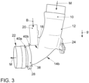
- Fig. 3
- eine dritte Ausführungsform einer erfindungsgemäßen Mediumleitung in einer Seitenansicht.
- In den
Fig. 1 bis 3 sind beispielhafte Ausführungsformen verschiedener erfindungsgemäßer Mediumleitungen 10 gezeigt. - Die in
Fig 1 . gezeigte Mediumleitung 10 ist in einem Längsschnitt dargestellt. Die Mediumleitung 10 umfasst einen Grundkörper 12 mit einer Umfangswand 14, die eine innere Umfangswand 14a und eine äußere Umfangswand 14b umfasst. Von der inneren Umfangswand 14a des Grundkörpers 12 wird ein Strömungsbereich 16 für ein nicht dargestelltes Medium begrenzt. Das Medium wird in Richtung der Hauptströmungsrichtung M durch den Strömungsbereich 16 des Grundkörpers 12 geführt. - Die in
Fig. 1 gezeigte Mediumleitung 10 ist Teil eines Ansaugtraktes einer nicht dargestellten Brennkraftmaschine. Bei der dargestellten Mediumleitung 10 handelt es sich um eine sogenannte Ansaughutze, die auch eine Blow-by-Gas-Einleitstelle 18 einer Blow-by-Gas-Leitung 20 umfasst. Das in Richtung der Hauptströmungsrichtung M strömende Medium ist dementsprechend Ansaugluft der nicht dargestellten Brennkraftmaschine. Durch die Blow-by-Gas-Leitung 20 werden Abgase aus dem nicht dargestellten Kurbelgehäuse der Brennkraftmaschine in Richtung des Pfeiles B in den Ansaugtrakt eingeleitet und der Ansaugluft beigemengt. Stromabwärts der Blow-by-Gas-Einleitstelle 18 strömt die Ansaugluft weiter in Richtung eines nicht dargestellten Verdichterrades eines ebenfalls nicht dargestellten Turboladers. - An dem Grundkörper 12 der Mediumleitung 10 ist in der gezeigten Ausführungsform ein optionales Anschlusselement, hier in Form einer Dichtmuffe 22, ausgebildet. Über dieses Anschlusselement kann die Mediumleitung 10 mit einem weiteren, nicht dargestellten Element verbunden werden, insbesondere mit einem weiteren Leitungselement.
- An dem Grundkörper 12 ist ferner eine optionale Anbindungsstruktur 24 ausgebildet, welche zur Fixierung der Mediumleitung 10 an einem anderen Element der Brennkraftmaschine bzw. an einem Karosserieelement eines Kraftfahrzeuges dient.
- In der in
Fig. 1 gezeigten ersten Ausführungsform sind an dem Grundkörper 12 gegenüber der Blow-by-Gas-Einleitstelle 18 der Blow-by-Gas-Leitung 20 außerhalb des Strömungsbereiches 16 Befestigungsstrukturen 26 in Form von zwei zueinander beabstandeten Materialverstärkungen 42 angeordnet. Die Befestigungsstruktur 26 ist fest mit einer äußeren Umfangsfläche 14b des Grundkörpers 12 verbunden. Ein Mittel zur Schwingungsanregung 28 ist an dem Grundkörper 12 befestigt ist. Bei der Befestigungsstruktur 26 handelt es sich vorliegend um eine Materialanhäufung, mit welchem das Mittel zur Schwingungsanregung 28 fest verbunden ist, beispielsweise verschweißt, verklebt oder verpresst. Das Mittel zur Schwingungsanregung 28 erzeugt von außen auf die äußere Umfangswand 14b gerichtete, radial nach innen wirkende Schwingungen. Die von dem Mittel zur Schwingungsanregung 28 erzeugte Hauptschwingungsrichtung des Grundkörpers 12 ist durch den Doppelpfeil S angedeutet. Als Mittel zur Schwingungsanregung 28 kommen insbesondere piezoelektrische Elemente oder elektromechanische Elemente in Betracht. Die Mittel zur Schwingungsanregung 28 sind weiter bevorzugt funktional mit einer externen Energieversorgung (nicht dargestellt) und/oder mit einer Steuerung (nicht dargestellt) zur bedarfsweisen Aktivierung verbunden, insbesondere um die Mittel zur Schwingungsanregung 28 bei Erreichen und Unterschreiten einer vorgegebenen Soll-Temperatur zu aktivieren. - Vorliegend ist nur ein Mittel zur Schwingungsanregung 28 außen an dem Grundkörper 12 angeordnet. Das Mittel zur Schwingungsanregung 28, erstreckt sich in den Bereich zwischen die Materialverstärkungen 42 bis zum äußeren Umfangswand 42. Ferner erstreckt es sich über einen Bereich von ungefähr 20 % des Außenumfangs des Grundkörpers 12.
- Optional können entlang des Außenumfangs und/oder in Hauptströmungsrichtung beabstandet zu dem gezeigten Mittel zur Schwingungsanregung 28 auch weitere solche Mittel zur Schwingungsanregung (nicht dargestellt) angeordnet sein.
- Wie bereits erwähnt, besteht eine erhöhte Gefahr einer Bildung von größeren Eiselementen - in Hauptströmungsrichtung M betrachtet - im Bereich der Blow-by-Gas-Einleitstelle 18 der Blow-by-Gas-Leitung 20, da wenn Wassertröpfchen, die in dem Blow-by-Gas enthalten sind, an den Umfangswänden der Blow-by-Gas-Leitung kondensieren, aus der Blow-by-Gas-Leitung 20 schwerkraftbedingt in die Mediumleitung 10 gelangen, insbesondere dort hineintropfen, oder anschließend in der Mediumleitung 10 gefrieren.
- Wenn die Blow-by-Gas-Leitung 20 in Einbaulage, wie in
Fig. 1 dargestellt, auf der Oberseite der Mediumleitung 10 angeordnet ist, so tropfen insbesondere größere Wassertröpfchen aus der Blow-by-Gas-Leitung 20 überwiegend auf die innere Umfangswand 14a auf der der Blow-by-Gas-Einleitstelle 18 gegenüberliegenden Unterseite der Mediumleitung 10. Durch die Anordnung des Mittels zur Schwingungsanregung 28 im Bereich der korrespondierenden äußeren Umfangswand 14b der Mediumleitung 10 wird der Entstehung größerer Eiselemente besonders effizient am Ort der Entstehung entgegengewirkt. - Im Folgenden werden zur Beschreibung weiterer Ausführungsformen für identische oder zumindest funktionsgleiche Elemente die gleichen Bezugszeichen verwendet, wie zur Beschreibung der ersten Ausführungsform in Verbindung mit
Fig. 1 . - Bei den in den
Fig. 2 undFig. 3 gezeigten Ausführungsformen handelt es sich um identische oder zumindest funktionsgleich ausgebildete Mediumleitungen 10, die sich von der ersten Ausführungsform im Wesentlichen durch die Anordnung und Anbindung des Mittels zur Schwingungsanregung 28 unterscheiden. - In
Fig. 2 ist eine zweite Ausführungsform einer Mediumleitung 10 in einer Seitenansicht dargestellt. Zu sehen ist daher nur die Mediumleitung 10 mit ihrer äußeren Umfangswand 14b. Wie bei der ersten Ausführungsform, ist hier ebenfalls gegenüberliegend der Blow-by-Gas-Einleitstelle 18 der Blow-by-Gas-Leitung 20 ein Mittel zur Schwingungsanregung 28 angeordnet. Das Mittel zur Schwingungsanregung 28 ist hier über ein den Grundkörper 12 vollständig umschließendes schematisch dargestelltes Band 30 an der äußeren Umfangswand 14b des Grundkörpers 12 befestigt. Das Mittel zur Schwingungsanregung 28 ist fest mit dem Band 30 verbunden. Das Band 30 weist einen geschlitzten Bereich 32 auf, wobei ein linker Abschnitt 34 des Bandes 30 die Blow-by-Gas-Leitung 20 stromabwärts umgreift und ein rechter Abschnitt 36 des Bandes 30 die Blow-By-Gas-Leitung 20 stromaufwärts umgreift. Dadurch wird sichergestellt, dass das Band 30 trotz der von dem Mittel zur Schwingungsanregung 28 erzeugten Schwingungen in seiner Position gehalten wird und sich insbesondere nicht in Hauptströmungsrichtung M relativ zu dem Grundkörper 12 bewegt. - Auch in der in
Fig. 3 gezeigten dritten Ausführungsform ist ein Mittel zur Schwingungsanregung 28 außenseitig an der äußeren Umfangswand 14b des Grundkörpers 12 der Mediumleitung 10 befestigt. In dieser Ausführungsform ist das Mittel zur Schwingungsanregung 28 stromabwärts der Blow-by-Gas-Einleitstelle 18 der Blow-by-Gas-Leitung 20, aber sich unmittelbar an die Blow-by-Gas-Einleitstelle 18 anschließend angeordnet. Das Mittel zur Schwingungsanregung 28 ist über eine den Grundkörper 12 vollständig umgebende, nur schematisch dargestellte Schelle 38 an dem Grundkörper 12 befestigt. Die Schelle 38 ist über sich zumindest teilweise über den Außenumfang des Grundkörpers 12 erstreckende, radial hervorragende Begrenzungselemente 40a, 40b gegenüber dem Grundkörper 12 insoweit festgelegt, als Relativbewegungen der Schelle 30 und der Mediumleitung 10 in Strömungsrichtung M entgegengewirkt wird bzw. solche Relativbewegungen nur innerhalb der Begrenzungselemente zugelassen werden. - Um Relativbewegungen zwischen einem Band 30 (
Fig. 2 ) bzw. einer Schelle 38 (Fig. 3 ) und dem Grundkörper 12 entgegenzuwirken, können an dem Band 30 bzw. der Schelle 38 auf der zur äußeren Umfangswand 14b gerichteten Seite Aufrauhungen und/oder Zähne ausgebildet sein, die zusammen mit Aufrauhungen und/oder komplementär ausgebildeten Zähnen im Bereich der äußeren Umfangswand 14b des Grundkörpers eine relative Axialfixierung bzw. eine Verzahnung des Bandes 30 bzw. der Schelle 38 mit der äußeren Umfangsfläche 14b des Grundkörpers 12 bewirken. - Die in der vorliegenden Beschreibung, in den Zeichnungen sowie in den Ansprüchen offenbarten Merkmale der Erfindung können sowohl einzeln als auch in beliebigen Kombinationen für die Verwirklichung der Erfindung in ihren verschiedenen Ausführungsformen wesentlich sein. Die Erfindung kann im Rahmen der Ansprüche variiert werden.
- Diesbezüglich wird insbesondere darauf verwiesen, dass die in den Figuren gezeigten Ausführungsformen der Mediumleitungen 10 aus Kunststoff im Blasformverfahren hergestellt sind. Erfindungsgemäße Mediumleitungen können aber auch aus metallischen Werkstoffen oder aus anderen geeigneten Werkstoffen und auch in anderen Herstellungsverfahren hergestellt sein, beispielsweise als Kunststoffspritzgießteile oder als metallische Gussteile.
-
- 10
- Mediumleitung
- 12
- Grundkörper
- 14
- Umfangswand
- 14a
- innere Umfangswand
- 14b
- äußere Umfangswand
- 16
- Strömungsbereich
- 18
- Blow-by-Gas-Einleitstelle
- 20
- Blow-by-Gas-Leitung
- 22
- Dichtmuffe
- 24
- Anbindungsstruktur
- 26
- Befestigungsstruktur
- 28
- Mittel zur Schwingungsanregung
- 30
- Band
- 32
- geschlitzter Bereich
- 34
- linker Abschnitt
- 36
- rechter Abschnitt
- 38
- Schelle
- 40a
- Begrenzungselement
- 40b
- Begrenzungselement
- 42
- Materialverstärkung
Claims (9)
- Mediumleitung einer Brennkraftmaschine mit einem Grundkörper (12) und mindestens einem, von einer Umfangswand (14) des Grundkörpers (12) begrenzten Strömungsbereich (16) und mit einer Blow-by-Gas-Einleitstelle (18), wobei der Strömungsbereich (16) zur Durchströmung von einem Medium vorgesehen ist, wobei an dem Grundkörper (12) außerhalb des Strömungsbereiches (16) im Bereich der Blow-by-Gas-Einleitstelle (18) mindestens ein Mittel zur Schwingungsanregung (28) des Grundkörpers (12) angeordnet ist, das ein mechanisches Lösen von kleineren Eiselementen ermöglicht,
dadurch gekennzeichnet,
dass das mindestens eine Mittel zur Schwingungsanregung (28) in Strömungsrichtung betrachtet im Bereich der Blow-by-Gas-Einleitstelle (18) außenseitig einer Ansaughutze und auf einer der Blow-by-Gas-Einleitstelle (18) gegenüberliegenden Seite an der Außenseite des Grundkörpers (12) der Mediumleitung (12) angeordnet ist. - Mediumleitung nach dem vorstehenden Anspruch, dadurch gekennzeichnet, dass der Grundkörper (12) Teil einer Ansaugleitung einer Brennkraftmaschine ist.
- Mediumleitung nach einem der vorstehenden Ansprüche, dadurch gekennzeichnet, dass das mindestens eine Mittel zur Schwingungsanregung (28) derart angeordnet und ausgebildet ist, dass von außen auf die Umfangswand (14) gerichtete, zumindest teilweise radial nach innen wirkende Schwingungen in den Grundkörper (12) einleitbar sind.
- Mediumleitung nach einem der vorstehenden Ansprüche, dadurch gekennzeichnet, dass das mindestens eine Mittel zur Schwingungsanregung (28) funktional mit einer externen Energieversorgung verbunden ist.
- Mediumleitung nach einem der vorstehenden Ansprüche, dadurch gekennzeichnet, dass mit dem Mittel zur Schwingungsanregung (28) Schwingungen mit einer Frequenz von mindestens 50 Hz erzeugbar sind.
- Mediumleitung nach einem der vorstehenden Ansprüche, dadurch gekennzeichnet, dass das Mittel zur Schwingungsanregung (28) zur Erzeugung von Schwingungen ausgelegt ist, deren Frequenz um maximal 10% von der Eigenfrequenz oder mindestens eines ganzzahligen Vielfachen der Eigenfrequenz des Grundkörpers (12) abweicht.
- Mediumleitung nach einem der vorstehenden Ansprüche, dadurch gekennzeichnet, dass sich das mindestens eine Mittel zur Schwingungsanregung (28) über mindestens 5% des Außenumfangs des Grundkörpers (12) erstreckt.
- Mediumleitung nach einem der vorstehenden Ansprüche, dadurch gekennzeichnet, dassa) an dem Grundkörper (12) eine Befestigungsstruktur (26) vorgesehen ist, um das Mittel zur Schwingungsanregung (28) an dem Grundkörper (12) zu fixieren und/oderb) dass das Mittel zur Schwingungsanregung (28) über eine den Grundkörper (12) zumindest teilweise umschließende Schelle (38) und/oder ein den Grundkörper (12) zumindest teilweise umschließendes Band (30) an dem Grundkörper (12) befestigt ist.
- Mediumleitung nach einem der vorstehenden Ansprüche, dadurch gekennzeichnet, dass das mindestens eine Mittel zur Schwingungsanregung (28) funktional mit einer Steuerung zur bedarfsweisen Aktvierung des mindestens einen Mittels zur Schwingungsanregung (28) gekoppelt ist.
Applications Claiming Priority (2)
| Application Number | Priority Date | Filing Date | Title |
|---|---|---|---|
| DE102016116147.0A DE102016116147A1 (de) | 2016-08-30 | 2016-08-30 | Mediumleitung einer Brennkraftmaschine |
| PCT/EP2017/071282 WO2018041699A1 (de) | 2016-08-30 | 2017-08-24 | Mediumleitung einer brennkraftmaschine |
Publications (2)
| Publication Number | Publication Date |
|---|---|
| EP3507480A1 EP3507480A1 (de) | 2019-07-10 |
| EP3507480B1 true EP3507480B1 (de) | 2024-05-29 |
Family
ID=59811288
Family Applications (1)
| Application Number | Title | Priority Date | Filing Date |
|---|---|---|---|
| EP17764339.2A Active EP3507480B1 (de) | 2016-08-30 | 2017-08-24 | Mediumleitung einer brennkraftmaschine |
Country Status (4)
| Country | Link |
|---|---|
| EP (1) | EP3507480B1 (de) |
| CN (1) | CN109642523B (de) |
| DE (1) | DE102016116147A1 (de) |
| WO (1) | WO2018041699A1 (de) |
Families Citing this family (1)
| Publication number | Priority date | Publication date | Assignee | Title |
|---|---|---|---|---|
| CN112096545A (zh) * | 2020-08-07 | 2020-12-18 | 东风汽车集团有限公司 | 一种空气管道组件 |
Citations (2)
| Publication number | Priority date | Publication date | Assignee | Title |
|---|---|---|---|---|
| US3186392A (en) * | 1963-12-23 | 1965-06-01 | Bran F Gregoric | Apparatus and method for improving combustion in an internal combustion engine |
| DE102008043768A1 (de) * | 2008-04-11 | 2009-10-15 | Ford Global Technologies, LLC, Dearborn | Mediumleitung |
Family Cites Families (7)
| Publication number | Priority date | Publication date | Assignee | Title |
|---|---|---|---|---|
| JPS57195848A (en) * | 1981-05-26 | 1982-12-01 | Mitsubishi Electric Corp | Mixture creating device |
| DE3819941A1 (de) | 1988-06-11 | 1989-12-21 | Heinz Hilke | Verfahren zum abreinigen der rohre in einem dampferzeuger und vorrichtung zur durchfuehrung des verfahrens |
| JPH10306751A (ja) * | 1997-05-07 | 1998-11-17 | Honda Motor Co Ltd | 吸気音低減装置 |
| DE102004062977A1 (de) * | 2004-12-22 | 2006-11-02 | Mahle Filtersysteme Gmbh | Kombination aus einem Körper und einem Generator |
| KR20070109691A (ko) * | 2006-05-12 | 2007-11-15 | 엘지전자 주식회사 | 냉장고 |
| CN104065016B (zh) * | 2014-07-18 | 2017-04-12 | 哈尔滨理工大学 | 利用外激谐振的输电线路在线防结冰防覆雪方法 |
| DE102015212041A1 (de) * | 2015-06-29 | 2016-12-29 | Mahle International Gmbh | Gasführende Einrichtung |
-
2016
- 2016-08-30 DE DE102016116147.0A patent/DE102016116147A1/de not_active Withdrawn
-
2017
- 2017-08-24 WO PCT/EP2017/071282 patent/WO2018041699A1/de not_active Ceased
- 2017-08-24 CN CN201780052908.9A patent/CN109642523B/zh active Active
- 2017-08-24 EP EP17764339.2A patent/EP3507480B1/de active Active
Patent Citations (2)
| Publication number | Priority date | Publication date | Assignee | Title |
|---|---|---|---|---|
| US3186392A (en) * | 1963-12-23 | 1965-06-01 | Bran F Gregoric | Apparatus and method for improving combustion in an internal combustion engine |
| DE102008043768A1 (de) * | 2008-04-11 | 2009-10-15 | Ford Global Technologies, LLC, Dearborn | Mediumleitung |
Also Published As
| Publication number | Publication date |
|---|---|
| EP3507480A1 (de) | 2019-07-10 |
| WO2018041699A1 (de) | 2018-03-08 |
| CN109642523A (zh) | 2019-04-16 |
| DE102016116147A1 (de) | 2018-03-01 |
| CN109642523B (zh) | 2022-03-01 |
Similar Documents
| Publication | Publication Date | Title |
|---|---|---|
| DE102008064075B4 (de) | Abgasreinigungseinrichtung für einen Motor | |
| EP2388455B1 (de) | Abgasturbolader | |
| EP2845636B1 (de) | Filterelement und Verfahren zur Herstellung eines Filterelements | |
| EP1512865A2 (de) | Schalldämpfer | |
| EP1352172A1 (de) | Schalldämpfer mit einer mehrzahl an resonanzkammern | |
| WO2012076416A1 (de) | Turbolader, der in den zylinderkopf eines motors integriert ist | |
| DE102011075643A1 (de) | Abgasanlagenkomponente | |
| EP1403506B1 (de) | Schalldämpfer zur Verringerung von Luftgeräuschen und Verfahren zur Herstellung desselben | |
| EP3507480B1 (de) | Mediumleitung einer brennkraftmaschine | |
| DE60310348T2 (de) | Verbesserung zu einem flexiblen Entkopplungsschlauch für eine Auspuffleitung eines Kraftfahrzeugmotors | |
| DE102011075450A1 (de) | Ventileinrichtung, Wastegate-Ventil und Turbolader | |
| EP2857693B1 (de) | Gebläseanordnung für ein Bodenpflegegerät | |
| WO2015078431A1 (de) | Ventileinheit, wie abgasklappeneinheit für kraftfahrzeuge | |
| DE102008020870A1 (de) | Klappenventil | |
| DE102011101612A1 (de) | Luftdurchlass für die Belüftung des Innenraumes eines Kraftfahrzeuges | |
| WO2012035163A1 (de) | Abgasbehandlungseinheit für eine abgasrückführleitung | |
| EP2915973B1 (de) | Trichter-Rohr-Anordnung | |
| EP4155513B1 (de) | Abgasführungsgehäuse | |
| DE102011102018A1 (de) | Klappeneinrichtung | |
| DE19857926A1 (de) | Ventilator eines Verbrennungsmotors | |
| DE102014003390B4 (de) | Antriebseinrichtung | |
| DE102012108829B4 (de) | Vorrichtung und Verfahren zur Schallreduktion | |
| DE102012207198A1 (de) | Vorrichtung zur Verringerung der Lärmemission von Luftansaugrohren | |
| EP1840350B1 (de) | Verkleidungsvorrichtung, insbesondere für Abgasrohre von Aggregaten | |
| EP1724443A1 (de) | Düsenring |
Legal Events
| Date | Code | Title | Description |
|---|---|---|---|
| STAA | Information on the status of an ep patent application or granted ep patent |
Free format text: STATUS: UNKNOWN |
|
| STAA | Information on the status of an ep patent application or granted ep patent |
Free format text: STATUS: THE INTERNATIONAL PUBLICATION HAS BEEN MADE |
|
| PUAI | Public reference made under article 153(3) epc to a published international application that has entered the european phase |
Free format text: ORIGINAL CODE: 0009012 |
|
| STAA | Information on the status of an ep patent application or granted ep patent |
Free format text: STATUS: REQUEST FOR EXAMINATION WAS MADE |
|
| 17P | Request for examination filed |
Effective date: 20190321 |
|
| AK | Designated contracting states |
Kind code of ref document: A1 Designated state(s): AL AT BE BG CH CY CZ DE DK EE ES FI FR GB GR HR HU IE IS IT LI LT LU LV MC MK MT NL NO PL PT RO RS SE SI SK SM TR |
|
| AX | Request for extension of the european patent |
Extension state: BA ME |
|
| DAV | Request for validation of the european patent (deleted) | ||
| DAX | Request for extension of the european patent (deleted) | ||
| STAA | Information on the status of an ep patent application or granted ep patent |
Free format text: STATUS: EXAMINATION IS IN PROGRESS |
|
| 17Q | First examination report despatched |
Effective date: 20200414 |
|
| GRAP | Despatch of communication of intention to grant a patent |
Free format text: ORIGINAL CODE: EPIDOSNIGR1 |
|
| STAA | Information on the status of an ep patent application or granted ep patent |
Free format text: STATUS: GRANT OF PATENT IS INTENDED |
|
| INTG | Intention to grant announced |
Effective date: 20240117 |
|
| GRAS | Grant fee paid |
Free format text: ORIGINAL CODE: EPIDOSNIGR3 |
|
| GRAA | (expected) grant |
Free format text: ORIGINAL CODE: 0009210 |
|
| STAA | Information on the status of an ep patent application or granted ep patent |
Free format text: STATUS: THE PATENT HAS BEEN GRANTED |
|
| AK | Designated contracting states |
Kind code of ref document: B1 Designated state(s): AL AT BE BG CH CY CZ DE DK EE ES FI FR GB GR HR HU IE IS IT LI LT LU LV MC MK MT NL NO PL PT RO RS SE SI SK SM TR |
|
| REG | Reference to a national code |
Ref country code: CH Ref legal event code: EP |
|
| P01 | Opt-out of the competence of the unified patent court (upc) registered |
Effective date: 20240513 |
|
| REG | Reference to a national code |
Ref country code: IE Ref legal event code: FG4D Free format text: LANGUAGE OF EP DOCUMENT: GERMAN |
|
| REG | Reference to a national code |
Ref country code: DE Ref legal event code: R096 Ref document number: 502017016146 Country of ref document: DE |
|
| REG | Reference to a national code |
Ref country code: LT Ref legal event code: MG9D |
|
| REG | Reference to a national code |
Ref country code: NL Ref legal event code: MP Effective date: 20240529 |
|
| PG25 | Lapsed in a contracting state [announced via postgrant information from national office to epo] |
Ref country code: IS Free format text: LAPSE BECAUSE OF FAILURE TO SUBMIT A TRANSLATION OF THE DESCRIPTION OR TO PAY THE FEE WITHIN THE PRESCRIBED TIME-LIMIT Effective date: 20240929 |
|
| PG25 | Lapsed in a contracting state [announced via postgrant information from national office to epo] |
Ref country code: BG Free format text: LAPSE BECAUSE OF FAILURE TO SUBMIT A TRANSLATION OF THE DESCRIPTION OR TO PAY THE FEE WITHIN THE PRESCRIBED TIME-LIMIT Effective date: 20240529 |
|
| PG25 | Lapsed in a contracting state [announced via postgrant information from national office to epo] |
Ref country code: HR Free format text: LAPSE BECAUSE OF FAILURE TO SUBMIT A TRANSLATION OF THE DESCRIPTION OR TO PAY THE FEE WITHIN THE PRESCRIBED TIME-LIMIT Effective date: 20240529 Ref country code: FI Free format text: LAPSE BECAUSE OF FAILURE TO SUBMIT A TRANSLATION OF THE DESCRIPTION OR TO PAY THE FEE WITHIN THE PRESCRIBED TIME-LIMIT Effective date: 20240529 |
|
| PG25 | Lapsed in a contracting state [announced via postgrant information from national office to epo] |
Ref country code: GR Free format text: LAPSE BECAUSE OF FAILURE TO SUBMIT A TRANSLATION OF THE DESCRIPTION OR TO PAY THE FEE WITHIN THE PRESCRIBED TIME-LIMIT Effective date: 20240830 |
|
| PG25 | Lapsed in a contracting state [announced via postgrant information from national office to epo] |
Ref country code: ES Free format text: LAPSE BECAUSE OF FAILURE TO SUBMIT A TRANSLATION OF THE DESCRIPTION OR TO PAY THE FEE WITHIN THE PRESCRIBED TIME-LIMIT Effective date: 20240529 |
|
| PG25 | Lapsed in a contracting state [announced via postgrant information from national office to epo] |
Ref country code: PL Free format text: LAPSE BECAUSE OF FAILURE TO SUBMIT A TRANSLATION OF THE DESCRIPTION OR TO PAY THE FEE WITHIN THE PRESCRIBED TIME-LIMIT Effective date: 20240529 |
|
| PG25 | Lapsed in a contracting state [announced via postgrant information from national office to epo] |
Ref country code: LV Free format text: LAPSE BECAUSE OF FAILURE TO SUBMIT A TRANSLATION OF THE DESCRIPTION OR TO PAY THE FEE WITHIN THE PRESCRIBED TIME-LIMIT Effective date: 20240529 |
|
| PG25 | Lapsed in a contracting state [announced via postgrant information from national office to epo] |
Ref country code: PL Free format text: LAPSE BECAUSE OF FAILURE TO SUBMIT A TRANSLATION OF THE DESCRIPTION OR TO PAY THE FEE WITHIN THE PRESCRIBED TIME-LIMIT Effective date: 20240529 Ref country code: NO Free format text: LAPSE BECAUSE OF FAILURE TO SUBMIT A TRANSLATION OF THE DESCRIPTION OR TO PAY THE FEE WITHIN THE PRESCRIBED TIME-LIMIT Effective date: 20240829 Ref country code: LV Free format text: LAPSE BECAUSE OF FAILURE TO SUBMIT A TRANSLATION OF THE DESCRIPTION OR TO PAY THE FEE WITHIN THE PRESCRIBED TIME-LIMIT Effective date: 20240529 Ref country code: IS Free format text: LAPSE BECAUSE OF FAILURE TO SUBMIT A TRANSLATION OF THE DESCRIPTION OR TO PAY THE FEE WITHIN THE PRESCRIBED TIME-LIMIT Effective date: 20240929 Ref country code: HR Free format text: LAPSE BECAUSE OF FAILURE TO SUBMIT A TRANSLATION OF THE DESCRIPTION OR TO PAY THE FEE WITHIN THE PRESCRIBED TIME-LIMIT Effective date: 20240529 Ref country code: GR Free format text: LAPSE BECAUSE OF FAILURE TO SUBMIT A TRANSLATION OF THE DESCRIPTION OR TO PAY THE FEE WITHIN THE PRESCRIBED TIME-LIMIT Effective date: 20240830 Ref country code: FI Free format text: LAPSE BECAUSE OF FAILURE TO SUBMIT A TRANSLATION OF THE DESCRIPTION OR TO PAY THE FEE WITHIN THE PRESCRIBED TIME-LIMIT Effective date: 20240529 Ref country code: ES Free format text: LAPSE BECAUSE OF FAILURE TO SUBMIT A TRANSLATION OF THE DESCRIPTION OR TO PAY THE FEE WITHIN THE PRESCRIBED TIME-LIMIT Effective date: 20240529 Ref country code: BG Free format text: LAPSE BECAUSE OF FAILURE TO SUBMIT A TRANSLATION OF THE DESCRIPTION OR TO PAY THE FEE WITHIN THE PRESCRIBED TIME-LIMIT Effective date: 20240529 Ref country code: RS Free format text: LAPSE BECAUSE OF FAILURE TO SUBMIT A TRANSLATION OF THE DESCRIPTION OR TO PAY THE FEE WITHIN THE PRESCRIBED TIME-LIMIT Effective date: 20240829 |
|
| PG25 | Lapsed in a contracting state [announced via postgrant information from national office to epo] |
Ref country code: NL Free format text: LAPSE BECAUSE OF FAILURE TO SUBMIT A TRANSLATION OF THE DESCRIPTION OR TO PAY THE FEE WITHIN THE PRESCRIBED TIME-LIMIT Effective date: 20240529 |
|
| PG25 | Lapsed in a contracting state [announced via postgrant information from national office to epo] |
Ref country code: NL Free format text: LAPSE BECAUSE OF FAILURE TO SUBMIT A TRANSLATION OF THE DESCRIPTION OR TO PAY THE FEE WITHIN THE PRESCRIBED TIME-LIMIT Effective date: 20240529 |
|
| PG25 | Lapsed in a contracting state [announced via postgrant information from national office to epo] |
Ref country code: DK Free format text: LAPSE BECAUSE OF FAILURE TO SUBMIT A TRANSLATION OF THE DESCRIPTION OR TO PAY THE FEE WITHIN THE PRESCRIBED TIME-LIMIT Effective date: 20240529 |
|
| PG25 | Lapsed in a contracting state [announced via postgrant information from national office to epo] |
Ref country code: EE Free format text: LAPSE BECAUSE OF FAILURE TO SUBMIT A TRANSLATION OF THE DESCRIPTION OR TO PAY THE FEE WITHIN THE PRESCRIBED TIME-LIMIT Effective date: 20240529 |
|
| PG25 | Lapsed in a contracting state [announced via postgrant information from national office to epo] |
Ref country code: CZ Free format text: LAPSE BECAUSE OF FAILURE TO SUBMIT A TRANSLATION OF THE DESCRIPTION OR TO PAY THE FEE WITHIN THE PRESCRIBED TIME-LIMIT Effective date: 20240529 |
|
| PG25 | Lapsed in a contracting state [announced via postgrant information from national office to epo] |
Ref country code: SK Free format text: LAPSE BECAUSE OF FAILURE TO SUBMIT A TRANSLATION OF THE DESCRIPTION OR TO PAY THE FEE WITHIN THE PRESCRIBED TIME-LIMIT Effective date: 20240529 Ref country code: RO Free format text: LAPSE BECAUSE OF FAILURE TO SUBMIT A TRANSLATION OF THE DESCRIPTION OR TO PAY THE FEE WITHIN THE PRESCRIBED TIME-LIMIT Effective date: 20240529 |
|
| PG25 | Lapsed in a contracting state [announced via postgrant information from national office to epo] |
Ref country code: SM Free format text: LAPSE BECAUSE OF FAILURE TO SUBMIT A TRANSLATION OF THE DESCRIPTION OR TO PAY THE FEE WITHIN THE PRESCRIBED TIME-LIMIT Effective date: 20240529 |
|
| PG25 | Lapsed in a contracting state [announced via postgrant information from national office to epo] |
Ref country code: SM Free format text: LAPSE BECAUSE OF FAILURE TO SUBMIT A TRANSLATION OF THE DESCRIPTION OR TO PAY THE FEE WITHIN THE PRESCRIBED TIME-LIMIT Effective date: 20240529 Ref country code: SK Free format text: LAPSE BECAUSE OF FAILURE TO SUBMIT A TRANSLATION OF THE DESCRIPTION OR TO PAY THE FEE WITHIN THE PRESCRIBED TIME-LIMIT Effective date: 20240529 Ref country code: RO Free format text: LAPSE BECAUSE OF FAILURE TO SUBMIT A TRANSLATION OF THE DESCRIPTION OR TO PAY THE FEE WITHIN THE PRESCRIBED TIME-LIMIT Effective date: 20240529 Ref country code: EE Free format text: LAPSE BECAUSE OF FAILURE TO SUBMIT A TRANSLATION OF THE DESCRIPTION OR TO PAY THE FEE WITHIN THE PRESCRIBED TIME-LIMIT Effective date: 20240529 Ref country code: DK Free format text: LAPSE BECAUSE OF FAILURE TO SUBMIT A TRANSLATION OF THE DESCRIPTION OR TO PAY THE FEE WITHIN THE PRESCRIBED TIME-LIMIT Effective date: 20240529 Ref country code: CZ Free format text: LAPSE BECAUSE OF FAILURE TO SUBMIT A TRANSLATION OF THE DESCRIPTION OR TO PAY THE FEE WITHIN THE PRESCRIBED TIME-LIMIT Effective date: 20240529 |
|
| PG25 | Lapsed in a contracting state [announced via postgrant information from national office to epo] |
Ref country code: IT Free format text: LAPSE BECAUSE OF FAILURE TO SUBMIT A TRANSLATION OF THE DESCRIPTION OR TO PAY THE FEE WITHIN THE PRESCRIBED TIME-LIMIT Effective date: 20240529 |
|
| REG | Reference to a national code |
Ref country code: DE Ref legal event code: R097 Ref document number: 502017016146 Country of ref document: DE |
|
| REG | Reference to a national code |
Ref country code: CH Ref legal event code: PL |
|
| PLBE | No opposition filed within time limit |
Free format text: ORIGINAL CODE: 0009261 |
|
| STAA | Information on the status of an ep patent application or granted ep patent |
Free format text: STATUS: NO OPPOSITION FILED WITHIN TIME LIMIT |
|
| PG25 | Lapsed in a contracting state [announced via postgrant information from national office to epo] |
Ref country code: LU Free format text: LAPSE BECAUSE OF NON-PAYMENT OF DUE FEES Effective date: 20240824 |
|
| PG25 | Lapsed in a contracting state [announced via postgrant information from national office to epo] |
Ref country code: MC Free format text: LAPSE BECAUSE OF FAILURE TO SUBMIT A TRANSLATION OF THE DESCRIPTION OR TO PAY THE FEE WITHIN THE PRESCRIBED TIME-LIMIT Effective date: 20240529 Ref country code: CH Free format text: LAPSE BECAUSE OF NON-PAYMENT OF DUE FEES Effective date: 20240831 Ref country code: SI Free format text: LAPSE BECAUSE OF FAILURE TO SUBMIT A TRANSLATION OF THE DESCRIPTION OR TO PAY THE FEE WITHIN THE PRESCRIBED TIME-LIMIT Effective date: 20240529 |
|
| 26N | No opposition filed |
Effective date: 20250303 |
|
| REG | Reference to a national code |
Ref country code: BE Ref legal event code: MM Effective date: 20240831 |
|
| PG25 | Lapsed in a contracting state [announced via postgrant information from national office to epo] |
Ref country code: BE Free format text: LAPSE BECAUSE OF NON-PAYMENT OF DUE FEES Effective date: 20240831 |
|
| PG25 | Lapsed in a contracting state [announced via postgrant information from national office to epo] |
Ref country code: IE Free format text: LAPSE BECAUSE OF NON-PAYMENT OF DUE FEES Effective date: 20240824 |
|
| PG25 | Lapsed in a contracting state [announced via postgrant information from national office to epo] |
Ref country code: SE Free format text: LAPSE BECAUSE OF FAILURE TO SUBMIT A TRANSLATION OF THE DESCRIPTION OR TO PAY THE FEE WITHIN THE PRESCRIBED TIME-LIMIT Effective date: 20240529 |
|
| PGFP | Annual fee paid to national office [announced via postgrant information from national office to epo] |
Ref country code: DE Payment date: 20250831 Year of fee payment: 9 |
|
| REG | Reference to a national code |
Ref country code: AT Ref legal event code: MM01 Ref document number: 1690840 Country of ref document: AT Kind code of ref document: T Effective date: 20240824 |
|
| PGFP | Annual fee paid to national office [announced via postgrant information from national office to epo] |
Ref country code: GB Payment date: 20250826 Year of fee payment: 9 |
|
| PG25 | Lapsed in a contracting state [announced via postgrant information from national office to epo] |
Ref country code: AT Free format text: LAPSE BECAUSE OF NON-PAYMENT OF DUE FEES Effective date: 20240824 |
|
| PGFP | Annual fee paid to national office [announced via postgrant information from national office to epo] |
Ref country code: FR Payment date: 20250825 Year of fee payment: 9 |
|
| PG25 | Lapsed in a contracting state [announced via postgrant information from national office to epo] |
Ref country code: PT Free format text: LAPSE BECAUSE OF NON-PAYMENT OF DUE FEES Effective date: 20240529 |
|
| PG25 | Lapsed in a contracting state [announced via postgrant information from national office to epo] |
Ref country code: CY Free format text: LAPSE BECAUSE OF FAILURE TO SUBMIT A TRANSLATION OF THE DESCRIPTION OR TO PAY THE FEE WITHIN THE PRESCRIBED TIME-LIMIT; INVALID AB INITIO Effective date: 20170824 |
|
| PG25 | Lapsed in a contracting state [announced via postgrant information from national office to epo] |
Ref country code: HU Free format text: LAPSE BECAUSE OF FAILURE TO SUBMIT A TRANSLATION OF THE DESCRIPTION OR TO PAY THE FEE WITHIN THE PRESCRIBED TIME-LIMIT; INVALID AB INITIO Effective date: 20170824 |