EP3506272A1 - Cloud-based medical analytics for medical facility segmented individualization of instrument function - Google Patents
Cloud-based medical analytics for medical facility segmented individualization of instrument function Download PDFInfo
- Publication number
- EP3506272A1 EP3506272A1 EP18193597.4A EP18193597A EP3506272A1 EP 3506272 A1 EP3506272 A1 EP 3506272A1 EP 18193597 A EP18193597 A EP 18193597A EP 3506272 A1 EP3506272 A1 EP 3506272A1
- Authority
- EP
- European Patent Office
- Prior art keywords
- medical
- data
- patient
- surgical
- cloud
- Prior art date
- Legal status (The legal status is an assumption and is not a legal conclusion. Google has not performed a legal analysis and makes no representation as to the accuracy of the status listed.)
- Pending
Links
- 238000000034 method Methods 0.000 claims abstract description 287
- 238000004891 communication Methods 0.000 claims abstract description 116
- 230000008859 change Effects 0.000 claims abstract description 92
- 230000015654 memory Effects 0.000 claims abstract description 88
- 238000012512 characterization method Methods 0.000 claims abstract description 58
- 230000002776 aggregation Effects 0.000 claims abstract description 20
- 238000004220 aggregation Methods 0.000 claims abstract description 20
- 238000004422 calculation algorithm Methods 0.000 claims description 34
- 230000004931 aggregating effect Effects 0.000 claims description 8
- 238000006467 substitution reaction Methods 0.000 claims description 8
- 210000001519 tissue Anatomy 0.000 description 97
- 238000010304 firing Methods 0.000 description 78
- 238000006073 displacement reaction Methods 0.000 description 71
- 239000012636 effector Substances 0.000 description 62
- 238000001356 surgical procedure Methods 0.000 description 62
- 230000000875 corresponding effect Effects 0.000 description 39
- 238000003384 imaging method Methods 0.000 description 35
- 230000006870 function Effects 0.000 description 33
- 238000003860 storage Methods 0.000 description 32
- 238000004458 analytical method Methods 0.000 description 31
- 238000012545 processing Methods 0.000 description 31
- 238000003032 molecular docking Methods 0.000 description 28
- 230000002452 interceptive effect Effects 0.000 description 27
- 230000004044 response Effects 0.000 description 27
- 239000012530 fluid Substances 0.000 description 26
- 238000005520 cutting process Methods 0.000 description 22
- 230000005540 biological transmission Effects 0.000 description 21
- 230000033001 locomotion Effects 0.000 description 21
- 238000012800 visualization Methods 0.000 description 21
- 238000010586 diagram Methods 0.000 description 20
- 230000008569 process Effects 0.000 description 20
- 239000000779 smoke Substances 0.000 description 20
- 230000001976 improved effect Effects 0.000 description 18
- 238000013519 translation Methods 0.000 description 17
- 230000002262 irrigation Effects 0.000 description 16
- 238000003973 irrigation Methods 0.000 description 16
- 238000002059 diagnostic imaging Methods 0.000 description 15
- 238000012517 data analytics Methods 0.000 description 14
- 230000003287 optical effect Effects 0.000 description 14
- 239000003990 capacitor Substances 0.000 description 13
- 238000003066 decision tree Methods 0.000 description 13
- 230000002980 postoperative effect Effects 0.000 description 13
- 230000009471 action Effects 0.000 description 12
- 238000007726 management method Methods 0.000 description 12
- 239000000463 material Substances 0.000 description 12
- 238000001228 spectrum Methods 0.000 description 12
- 238000013475 authorization Methods 0.000 description 11
- 238000012986 modification Methods 0.000 description 11
- 230000004048 modification Effects 0.000 description 11
- 210000000115 thoracic cavity Anatomy 0.000 description 11
- 230000008901 benefit Effects 0.000 description 10
- 230000006835 compression Effects 0.000 description 10
- 238000007906 compression Methods 0.000 description 10
- 230000005355 Hall effect Effects 0.000 description 9
- 230000001276 controlling effect Effects 0.000 description 9
- 230000003993 interaction Effects 0.000 description 9
- 238000002955 isolation Methods 0.000 description 9
- 238000005259 measurement Methods 0.000 description 9
- 238000012544 monitoring process Methods 0.000 description 9
- 230000002093 peripheral effect Effects 0.000 description 9
- 238000012546 transfer Methods 0.000 description 9
- 230000007704 transition Effects 0.000 description 9
- 238000013480 data collection Methods 0.000 description 8
- 230000000694 effects Effects 0.000 description 8
- 238000005516 engineering process Methods 0.000 description 8
- 210000004072 lung Anatomy 0.000 description 8
- 239000000523 sample Substances 0.000 description 8
- 238000013538 segmental resection Methods 0.000 description 8
- 238000012806 monitoring device Methods 0.000 description 7
- 238000011144 upstream manufacturing Methods 0.000 description 7
- 208000025247 virus-associated trichodysplasia spinulosa Diseases 0.000 description 7
- 206010002091 Anaesthesia Diseases 0.000 description 6
- 230000037005 anaesthesia Effects 0.000 description 6
- 230000000903 blocking effect Effects 0.000 description 6
- 238000013461 design Methods 0.000 description 6
- 238000005457 optimization Methods 0.000 description 6
- 238000005070 sampling Methods 0.000 description 6
- 238000007789 sealing Methods 0.000 description 6
- 238000011282 treatment Methods 0.000 description 6
- 230000004913 activation Effects 0.000 description 5
- 230000003044 adaptive effect Effects 0.000 description 5
- 230000006399 behavior Effects 0.000 description 5
- 238000003339 best practice Methods 0.000 description 5
- 230000000740 bleeding effect Effects 0.000 description 5
- 238000004364 calculation method Methods 0.000 description 5
- 210000004027 cell Anatomy 0.000 description 5
- 230000003750 conditioning effect Effects 0.000 description 5
- SYHGEUNFJIGTRX-UHFFFAOYSA-N methylenedioxypyrovalerone Chemical compound C=1C=C2OCOC2=CC=1C(=O)C(CCC)N1CCCC1 SYHGEUNFJIGTRX-UHFFFAOYSA-N 0.000 description 5
- 238000012913 prioritisation Methods 0.000 description 5
- 230000001954 sterilising effect Effects 0.000 description 5
- 238000004659 sterilization and disinfection Methods 0.000 description 5
- 238000004804 winding Methods 0.000 description 5
- 210000003484 anatomy Anatomy 0.000 description 4
- 230000009286 beneficial effect Effects 0.000 description 4
- 238000004590 computer program Methods 0.000 description 4
- 238000007405 data analysis Methods 0.000 description 4
- 238000002224 dissection Methods 0.000 description 4
- 230000001939 inductive effect Effects 0.000 description 4
- 230000000670 limiting effect Effects 0.000 description 4
- 230000007246 mechanism Effects 0.000 description 4
- 239000000203 mixture Substances 0.000 description 4
- 230000009467 reduction Effects 0.000 description 4
- 230000002441 reversible effect Effects 0.000 description 4
- 230000001360 synchronised effect Effects 0.000 description 4
- 238000001429 visible spectrum Methods 0.000 description 4
- 239000003795 chemical substances by application Substances 0.000 description 3
- 239000004020 conductor Substances 0.000 description 3
- 238000010276 construction Methods 0.000 description 3
- 230000005670 electromagnetic radiation Effects 0.000 description 3
- 238000004520 electroporation Methods 0.000 description 3
- 238000005286 illumination Methods 0.000 description 3
- 230000002427 irreversible effect Effects 0.000 description 3
- 230000036961 partial effect Effects 0.000 description 3
- 230000002829 reductive effect Effects 0.000 description 3
- 238000007619 statistical method Methods 0.000 description 3
- 238000012384 transportation and delivery Methods 0.000 description 3
- 230000000007 visual effect Effects 0.000 description 3
- PJVWKTKQMONHTI-UHFFFAOYSA-N warfarin Chemical compound OC=1C2=CC=CC=C2OC(=O)C=1C(CC(=O)C)C1=CC=CC=C1 PJVWKTKQMONHTI-UHFFFAOYSA-N 0.000 description 3
- 229960005080 warfarin Drugs 0.000 description 3
- 239000002699 waste material Substances 0.000 description 3
- 239000005552 B01AC04 - Clopidogrel Substances 0.000 description 2
- HBBGRARXTFLTSG-UHFFFAOYSA-N Lithium ion Chemical compound [Li+] HBBGRARXTFLTSG-UHFFFAOYSA-N 0.000 description 2
- 230000002159 abnormal effect Effects 0.000 description 2
- 238000007681 bariatric surgery Methods 0.000 description 2
- 230000036772 blood pressure Effects 0.000 description 2
- 238000000701 chemical imaging Methods 0.000 description 2
- 239000003638 chemical reducing agent Substances 0.000 description 2
- GKTWGGQPFAXNFI-HNNXBMFYSA-N clopidogrel Chemical compound C1([C@H](N2CC=3C=CSC=3CC2)C(=O)OC)=CC=CC=C1Cl GKTWGGQPFAXNFI-HNNXBMFYSA-N 0.000 description 2
- 230000015271 coagulation Effects 0.000 description 2
- 238000005345 coagulation Methods 0.000 description 2
- 230000002596 correlated effect Effects 0.000 description 2
- 238000001514 detection method Methods 0.000 description 2
- 238000002405 diagnostic procedure Methods 0.000 description 2
- 238000009826 distribution Methods 0.000 description 2
- 229940079593 drug Drugs 0.000 description 2
- 239000003814 drug Substances 0.000 description 2
- 230000005669 field effect Effects 0.000 description 2
- 238000001914 filtration Methods 0.000 description 2
- 230000006872 improvement Effects 0.000 description 2
- 229910001416 lithium ion Inorganic materials 0.000 description 2
- 230000007774 longterm Effects 0.000 description 2
- 238000010801 machine learning Methods 0.000 description 2
- 238000002483 medication Methods 0.000 description 2
- 229910044991 metal oxide Inorganic materials 0.000 description 2
- 150000004706 metal oxides Chemical class 0.000 description 2
- 230000008520 organization Effects 0.000 description 2
- 229910052760 oxygen Inorganic materials 0.000 description 2
- 230000010412 perfusion Effects 0.000 description 2
- 229940020573 plavix Drugs 0.000 description 2
- 238000011084 recovery Methods 0.000 description 2
- 239000004065 semiconductor Substances 0.000 description 2
- 238000012360 testing method Methods 0.000 description 2
- 230000001225 therapeutic effect Effects 0.000 description 2
- 238000002604 ultrasonography Methods 0.000 description 2
- 230000002792 vascular Effects 0.000 description 2
- 238000009423 ventilation Methods 0.000 description 2
- PGOHTUIFYSHAQG-LJSDBVFPSA-N (2S)-6-amino-2-[[(2S)-5-amino-2-[[(2S)-2-[[(2S)-2-[[(2S)-2-[[(2S)-4-amino-2-[[(2S)-2-[[(2S)-2-[[(2S)-2-[[(2S)-2-[[(2S)-5-amino-2-[[(2S)-5-amino-2-[[(2S)-2-[[(2S)-2-[[(2S)-2-[[(2S,3R)-2-[[(2S)-5-amino-2-[[(2S)-2-[[(2S)-2-[[(2S,3R)-2-[[(2S)-2-[[(2S)-2-[[(2S)-2-[[(2S)-2-[[(2S)-5-amino-2-[[(2S)-1-[(2S,3R)-2-[[(2S)-2-[[(2S)-2-[[(2R)-2-[[(2S)-2-[[(2S)-2-[[2-[[(2S)-2-[[(2S)-2-[[(2S)-2-[[(2S)-1-[(2S)-2-[[(2S)-2-[[(2S)-2-[[(2S)-2-amino-4-methylsulfanylbutanoyl]amino]-3-(1H-indol-3-yl)propanoyl]amino]-5-carbamimidamidopentanoyl]amino]propanoyl]pyrrolidine-2-carbonyl]amino]-3-methylbutanoyl]amino]-4-methylpentanoyl]amino]-4-methylpentanoyl]amino]acetyl]amino]-3-hydroxypropanoyl]amino]-4-methylpentanoyl]amino]-3-sulfanylpropanoyl]amino]-4-methylsulfanylbutanoyl]amino]-5-carbamimidamidopentanoyl]amino]-3-hydroxybutanoyl]pyrrolidine-2-carbonyl]amino]-5-oxopentanoyl]amino]-3-hydroxypropanoyl]amino]-3-hydroxypropanoyl]amino]-3-(1H-imidazol-5-yl)propanoyl]amino]-4-methylpentanoyl]amino]-3-hydroxybutanoyl]amino]-3-(1H-indol-3-yl)propanoyl]amino]-5-carbamimidamidopentanoyl]amino]-5-oxopentanoyl]amino]-3-hydroxybutanoyl]amino]-3-hydroxypropanoyl]amino]-3-carboxypropanoyl]amino]-3-hydroxypropanoyl]amino]-5-oxopentanoyl]amino]-5-oxopentanoyl]amino]-3-phenylpropanoyl]amino]-5-carbamimidamidopentanoyl]amino]-3-methylbutanoyl]amino]-4-methylpentanoyl]amino]-4-oxobutanoyl]amino]-5-carbamimidamidopentanoyl]amino]-3-(1H-indol-3-yl)propanoyl]amino]-4-carboxybutanoyl]amino]-5-oxopentanoyl]amino]hexanoic acid Chemical compound CSCC[C@H](N)C(=O)N[C@@H](Cc1c[nH]c2ccccc12)C(=O)N[C@@H](CCCNC(N)=N)C(=O)N[C@@H](C)C(=O)N1CCC[C@H]1C(=O)N[C@@H](C(C)C)C(=O)N[C@@H](CC(C)C)C(=O)N[C@@H](CC(C)C)C(=O)NCC(=O)N[C@@H](CO)C(=O)N[C@@H](CC(C)C)C(=O)N[C@@H](CS)C(=O)N[C@@H](CCSC)C(=O)N[C@@H](CCCNC(N)=N)C(=O)N[C@@H]([C@@H](C)O)C(=O)N1CCC[C@H]1C(=O)N[C@@H](CCC(N)=O)C(=O)N[C@@H](CO)C(=O)N[C@@H](CO)C(=O)N[C@@H](Cc1cnc[nH]1)C(=O)N[C@@H](CC(C)C)C(=O)N[C@@H]([C@@H](C)O)C(=O)N[C@@H](Cc1c[nH]c2ccccc12)C(=O)N[C@@H](CCCNC(N)=N)C(=O)N[C@@H](CCC(N)=O)C(=O)N[C@@H]([C@@H](C)O)C(=O)N[C@@H](CO)C(=O)N[C@@H](CC(O)=O)C(=O)N[C@@H](CO)C(=O)N[C@@H](CCC(N)=O)C(=O)N[C@@H](CCC(N)=O)C(=O)N[C@@H](Cc1ccccc1)C(=O)N[C@@H](CCCNC(N)=N)C(=O)N[C@@H](C(C)C)C(=O)N[C@@H](CC(C)C)C(=O)N[C@@H](CC(N)=O)C(=O)N[C@@H](CCCNC(N)=N)C(=O)N[C@@H](Cc1c[nH]c2ccccc12)C(=O)N[C@@H](CCC(O)=O)C(=O)N[C@@H](CCC(N)=O)C(=O)N[C@@H](CCCCN)C(O)=O PGOHTUIFYSHAQG-LJSDBVFPSA-N 0.000 description 1
- 241000238366 Cephalopoda Species 0.000 description 1
- RYGMFSIKBFXOCR-UHFFFAOYSA-N Copper Chemical compound [Cu] RYGMFSIKBFXOCR-UHFFFAOYSA-N 0.000 description 1
- 108010023321 Factor VII Proteins 0.000 description 1
- 102000009123 Fibrin Human genes 0.000 description 1
- 108010073385 Fibrin Proteins 0.000 description 1
- BWGVNKXGVNDBDI-UHFFFAOYSA-N Fibrin monomer Chemical compound CNC(=O)CNC(=O)CN BWGVNKXGVNDBDI-UHFFFAOYSA-N 0.000 description 1
- FAPWRFPIFSIZLT-UHFFFAOYSA-M Sodium chloride Chemical compound [Na+].[Cl-] FAPWRFPIFSIZLT-UHFFFAOYSA-M 0.000 description 1
- 206010042635 Suspiciousness Diseases 0.000 description 1
- 108010000499 Thromboplastin Proteins 0.000 description 1
- 102000002262 Thromboplastin Human genes 0.000 description 1
- 229930003448 Vitamin K Natural products 0.000 description 1
- 230000003321 amplification Effects 0.000 description 1
- 238000013459 approach Methods 0.000 description 1
- 238000003491 array Methods 0.000 description 1
- 210000001367 artery Anatomy 0.000 description 1
- 230000000712 assembly Effects 0.000 description 1
- 238000000429 assembly Methods 0.000 description 1
- QVGXLLKOCUKJST-UHFFFAOYSA-N atomic oxygen Chemical compound [O] QVGXLLKOCUKJST-UHFFFAOYSA-N 0.000 description 1
- 230000033228 biological regulation Effects 0.000 description 1
- 230000015572 biosynthetic process Effects 0.000 description 1
- 238000006243 chemical reaction Methods 0.000 description 1
- 230000000295 complement effect Effects 0.000 description 1
- 239000002131 composite material Substances 0.000 description 1
- 230000001143 conditioned effect Effects 0.000 description 1
- 238000012790 confirmation Methods 0.000 description 1
- 229910052802 copper Inorganic materials 0.000 description 1
- 239000010949 copper Substances 0.000 description 1
- 238000013500 data storage Methods 0.000 description 1
- 230000007423 decrease Effects 0.000 description 1
- 230000007547 defect Effects 0.000 description 1
- 230000007812 deficiency Effects 0.000 description 1
- 230000001419 dependent effect Effects 0.000 description 1
- 230000000881 depressing effect Effects 0.000 description 1
- 230000003745 detangling effect Effects 0.000 description 1
- 201000010099 disease Diseases 0.000 description 1
- 208000037265 diseases, disorders, signs and symptoms Diseases 0.000 description 1
- 230000008030 elimination Effects 0.000 description 1
- 238000003379 elimination reaction Methods 0.000 description 1
- 238000010336 energy treatment Methods 0.000 description 1
- 230000002708 enhancing effect Effects 0.000 description 1
- 238000011156 evaluation Methods 0.000 description 1
- 230000007717 exclusion Effects 0.000 description 1
- 238000000605 extraction Methods 0.000 description 1
- 230000002349 favourable effect Effects 0.000 description 1
- 239000000835 fiber Substances 0.000 description 1
- 229950003499 fibrin Drugs 0.000 description 1
- 230000037406 food intake Effects 0.000 description 1
- 230000005251 gamma ray Effects 0.000 description 1
- 230000014509 gene expression Effects 0.000 description 1
- 238000005534 hematocrit Methods 0.000 description 1
- 208000014617 hemorrhoid Diseases 0.000 description 1
- 230000036512 infertility Effects 0.000 description 1
- 238000003780 insertion Methods 0.000 description 1
- 230000037431 insertion Effects 0.000 description 1
- 230000010354 integration Effects 0.000 description 1
- 230000003601 intercostal effect Effects 0.000 description 1
- 230000004807 localization Effects 0.000 description 1
- 210000001165 lymph node Anatomy 0.000 description 1
- 238000004519 manufacturing process Methods 0.000 description 1
- 229940127554 medical product Drugs 0.000 description 1
- 230000005055 memory storage Effects 0.000 description 1
- 244000005700 microbiome Species 0.000 description 1
- 238000002324 minimally invasive surgery Methods 0.000 description 1
- 238000012978 minimally invasive surgical procedure Methods 0.000 description 1
- 230000000116 mitigating effect Effects 0.000 description 1
- 239000003607 modifier Substances 0.000 description 1
- 230000004899 motility Effects 0.000 description 1
- 238000003058 natural language processing Methods 0.000 description 1
- 230000006855 networking Effects 0.000 description 1
- 238000003199 nucleic acid amplification method Methods 0.000 description 1
- 230000000399 orthopedic effect Effects 0.000 description 1
- 239000001301 oxygen Substances 0.000 description 1
- 230000003071 parasitic effect Effects 0.000 description 1
- 230000007170 pathology Effects 0.000 description 1
- 238000003909 pattern recognition Methods 0.000 description 1
- 230000000737 periodic effect Effects 0.000 description 1
- SHUZOJHMOBOZST-UHFFFAOYSA-N phylloquinone Natural products CC(C)CCCCC(C)CCC(C)CCCC(=CCC1=C(C)C(=O)c2ccccc2C1=O)C SHUZOJHMOBOZST-UHFFFAOYSA-N 0.000 description 1
- 230000037081 physical activity Effects 0.000 description 1
- 230000036316 preload Effects 0.000 description 1
- 230000002035 prolonged effect Effects 0.000 description 1
- 230000000644 propagated effect Effects 0.000 description 1
- 210000001187 pylorus Anatomy 0.000 description 1
- 230000005855 radiation Effects 0.000 description 1
- 238000011160 research Methods 0.000 description 1
- 238000013468 resource allocation Methods 0.000 description 1
- 230000029058 respiratory gaseous exchange Effects 0.000 description 1
- 238000002432 robotic surgery Methods 0.000 description 1
- 239000000565 sealant Substances 0.000 description 1
- 230000035945 sensitivity Effects 0.000 description 1
- 230000001953 sensory effect Effects 0.000 description 1
- 238000000926 separation method Methods 0.000 description 1
- 238000012163 sequencing technique Methods 0.000 description 1
- 230000011664 signaling Effects 0.000 description 1
- 238000007682 sleeve gastrectomy Methods 0.000 description 1
- 239000011780 sodium chloride Substances 0.000 description 1
- 239000007787 solid Substances 0.000 description 1
- 235000021055 solid food Nutrition 0.000 description 1
- 239000000758 substrate Substances 0.000 description 1
- 230000000153 supplemental effect Effects 0.000 description 1
- 230000008093 supporting effect Effects 0.000 description 1
- 238000003786 synthesis reaction Methods 0.000 description 1
- 238000012876 topography Methods 0.000 description 1
- 210000003462 vein Anatomy 0.000 description 1
- 235000019168 vitamin K Nutrition 0.000 description 1
- 239000011712 vitamin K Substances 0.000 description 1
- 150000003721 vitamin K derivatives Chemical class 0.000 description 1
- 229940046010 vitamin k Drugs 0.000 description 1
Images


Classifications
-
- A—HUMAN NECESSITIES
- A61—MEDICAL OR VETERINARY SCIENCE; HYGIENE
- A61B—DIAGNOSIS; SURGERY; IDENTIFICATION
- A61B34/00—Computer-aided surgery; Manipulators or robots specially adapted for use in surgery
- A61B34/25—User interfaces for surgical systems
-
- G—PHYSICS
- G16—INFORMATION AND COMMUNICATION TECHNOLOGY [ICT] SPECIALLY ADAPTED FOR SPECIFIC APPLICATION FIELDS
- G16H—HEALTHCARE INFORMATICS, i.e. INFORMATION AND COMMUNICATION TECHNOLOGY [ICT] SPECIALLY ADAPTED FOR THE HANDLING OR PROCESSING OF MEDICAL OR HEALTHCARE DATA
- G16H50/00—ICT specially adapted for medical diagnosis, medical simulation or medical data mining; ICT specially adapted for detecting, monitoring or modelling epidemics or pandemics
- G16H50/70—ICT specially adapted for medical diagnosis, medical simulation or medical data mining; ICT specially adapted for detecting, monitoring or modelling epidemics or pandemics for mining of medical data, e.g. analysing previous cases of other patients
-
- A—HUMAN NECESSITIES
- A61—MEDICAL OR VETERINARY SCIENCE; HYGIENE
- A61B—DIAGNOSIS; SURGERY; IDENTIFICATION
- A61B34/00—Computer-aided surgery; Manipulators or robots specially adapted for use in surgery
- A61B34/30—Surgical robots
- A61B34/35—Surgical robots for telesurgery
-
- A—HUMAN NECESSITIES
- A61—MEDICAL OR VETERINARY SCIENCE; HYGIENE
- A61B—DIAGNOSIS; SURGERY; IDENTIFICATION
- A61B34/00—Computer-aided surgery; Manipulators or robots specially adapted for use in surgery
- A61B34/70—Manipulators specially adapted for use in surgery
- A61B34/76—Manipulators having means for providing feel, e.g. force or tactile feedback
-
- G—PHYSICS
- G16—INFORMATION AND COMMUNICATION TECHNOLOGY [ICT] SPECIALLY ADAPTED FOR SPECIFIC APPLICATION FIELDS
- G16H—HEALTHCARE INFORMATICS, i.e. INFORMATION AND COMMUNICATION TECHNOLOGY [ICT] SPECIALLY ADAPTED FOR THE HANDLING OR PROCESSING OF MEDICAL OR HEALTHCARE DATA
- G16H20/00—ICT specially adapted for therapies or health-improving plans, e.g. for handling prescriptions, for steering therapy or for monitoring patient compliance
- G16H20/40—ICT specially adapted for therapies or health-improving plans, e.g. for handling prescriptions, for steering therapy or for monitoring patient compliance relating to mechanical, radiation or invasive therapies, e.g. surgery, laser therapy, dialysis or acupuncture
-
- A—HUMAN NECESSITIES
- A61—MEDICAL OR VETERINARY SCIENCE; HYGIENE
- A61B—DIAGNOSIS; SURGERY; IDENTIFICATION
- A61B17/00—Surgical instruments, devices or methods, e.g. tourniquets
- A61B2017/00017—Electrical control of surgical instruments
- A61B2017/00199—Electrical control of surgical instruments with a console, e.g. a control panel with a display
-
- A—HUMAN NECESSITIES
- A61—MEDICAL OR VETERINARY SCIENCE; HYGIENE
- A61B—DIAGNOSIS; SURGERY; IDENTIFICATION
- A61B17/00—Surgical instruments, devices or methods, e.g. tourniquets
- A61B2017/00017—Electrical control of surgical instruments
- A61B2017/00221—Electrical control of surgical instruments with wireless transmission of data, e.g. by infrared radiation or radiowaves
-
- A—HUMAN NECESSITIES
- A61—MEDICAL OR VETERINARY SCIENCE; HYGIENE
- A61B—DIAGNOSIS; SURGERY; IDENTIFICATION
- A61B17/00—Surgical instruments, devices or methods, e.g. tourniquets
- A61B2017/00017—Electrical control of surgical instruments
- A61B2017/00225—Systems for controlling multiple different instruments, e.g. microsurgical systems
-
- A—HUMAN NECESSITIES
- A61—MEDICAL OR VETERINARY SCIENCE; HYGIENE
- A61B—DIAGNOSIS; SURGERY; IDENTIFICATION
- A61B17/00—Surgical instruments, devices or methods, e.g. tourniquets
- A61B2017/00477—Coupling
-
- A—HUMAN NECESSITIES
- A61—MEDICAL OR VETERINARY SCIENCE; HYGIENE
- A61B—DIAGNOSIS; SURGERY; IDENTIFICATION
- A61B34/00—Computer-aided surgery; Manipulators or robots specially adapted for use in surgery
- A61B34/25—User interfaces for surgical systems
- A61B2034/252—User interfaces for surgical systems indicating steps of a surgical procedure
-
- A—HUMAN NECESSITIES
- A61—MEDICAL OR VETERINARY SCIENCE; HYGIENE
- A61B—DIAGNOSIS; SURGERY; IDENTIFICATION
- A61B34/00—Computer-aided surgery; Manipulators or robots specially adapted for use in surgery
- A61B34/25—User interfaces for surgical systems
- A61B2034/254—User interfaces for surgical systems being adapted depending on the stage of the surgical procedure
-
- A—HUMAN NECESSITIES
- A61—MEDICAL OR VETERINARY SCIENCE; HYGIENE
- A61B—DIAGNOSIS; SURGERY; IDENTIFICATION
- A61B34/00—Computer-aided surgery; Manipulators or robots specially adapted for use in surgery
- A61B34/30—Surgical robots
- A61B2034/302—Surgical robots specifically adapted for manipulations within body cavities, e.g. within abdominal or thoracic cavities
-
- A—HUMAN NECESSITIES
- A61—MEDICAL OR VETERINARY SCIENCE; HYGIENE
- A61B—DIAGNOSIS; SURGERY; IDENTIFICATION
- A61B34/00—Computer-aided surgery; Manipulators or robots specially adapted for use in surgery
- A61B34/30—Surgical robots
- A61B2034/304—Surgical robots including a freely orientable platform, e.g. so called 'Stewart platforms'
-
- A—HUMAN NECESSITIES
- A61—MEDICAL OR VETERINARY SCIENCE; HYGIENE
- A61B—DIAGNOSIS; SURGERY; IDENTIFICATION
- A61B34/00—Computer-aided surgery; Manipulators or robots specially adapted for use in surgery
- A61B34/30—Surgical robots
- A61B2034/305—Details of wrist mechanisms at distal ends of robotic arms
-
- A—HUMAN NECESSITIES
- A61—MEDICAL OR VETERINARY SCIENCE; HYGIENE
- A61B—DIAGNOSIS; SURGERY; IDENTIFICATION
- A61B34/00—Computer-aided surgery; Manipulators or robots specially adapted for use in surgery
- A61B34/70—Manipulators specially adapted for use in surgery
- A61B34/77—Manipulators with motion or force scaling
-
- A—HUMAN NECESSITIES
- A61—MEDICAL OR VETERINARY SCIENCE; HYGIENE
- A61B—DIAGNOSIS; SURGERY; IDENTIFICATION
- A61B90/00—Instruments, implements or accessories specially adapted for surgery or diagnosis and not covered by any of the groups A61B1/00 - A61B50/00, e.g. for luxation treatment or for protecting wound edges
- A61B90/36—Image-producing devices or illumination devices not otherwise provided for
- A61B90/361—Image-producing devices, e.g. surgical cameras
-
- A—HUMAN NECESSITIES
- A61—MEDICAL OR VETERINARY SCIENCE; HYGIENE
- A61B—DIAGNOSIS; SURGERY; IDENTIFICATION
- A61B90/00—Instruments, implements or accessories specially adapted for surgery or diagnosis and not covered by any of the groups A61B1/00 - A61B50/00, e.g. for luxation treatment or for protecting wound edges
- A61B90/36—Image-producing devices or illumination devices not otherwise provided for
- A61B90/37—Surgical systems with images on a monitor during operation
-
- G—PHYSICS
- G16—INFORMATION AND COMMUNICATION TECHNOLOGY [ICT] SPECIALLY ADAPTED FOR SPECIFIC APPLICATION FIELDS
- G16H—HEALTHCARE INFORMATICS, i.e. INFORMATION AND COMMUNICATION TECHNOLOGY [ICT] SPECIALLY ADAPTED FOR THE HANDLING OR PROCESSING OF MEDICAL OR HEALTHCARE DATA
- G16H40/00—ICT specially adapted for the management or administration of healthcare resources or facilities; ICT specially adapted for the management or operation of medical equipment or devices
- G16H40/60—ICT specially adapted for the management or administration of healthcare resources or facilities; ICT specially adapted for the management or operation of medical equipment or devices for the operation of medical equipment or devices
Definitions
- the present disclosure relates to various surgical systems.
- medical systems and facilities are often slower to implement systems or procedures utilizing newer and improved technologies due to patient safety and a general desire for maintaining traditional practices.
- medical systems and facilities may lack communication and shared knowledge with other neighboring or similarly situated facilities as a result.
- a cloud based analytics medical system comprises: at least one processor; at least one memory communicatively coupled to the at least one processor; an input/output interface configured for accessing data from a plurality of medical hub communication devices, each communicatively coupled to at least one surgical instrument; and a database residing in the at least one memory and configured to store the data.
- the at least one memory stores instructions executable by the at least one processor to: generate common medical usage patterns of medical devices based on an aggregation of usage data for the medical devices from the plurality of medical hubs; and aggregate patient outcome data from the plurality of medical hubs.
- the patient outcome data comprises: data pertaining to steps performed and corresponding timings for each step in patient procedures; data pertaining to allocation of medical resources used in the patient procedures; for each datum pertaining to the medical resource: location data indicating which medical facility said medical resource was allocated to; and for each datum pertaining to the patient procedure: data indicative of the outcome of the patient procedure; data indicative of a biographical characterization about the patient; and data indicative of a physiologic characterization about the patient.
- the at least one memory further stores instructions executable by the at least one processor to: for data indicative of a positive outcome of the patient procedure, determine a biographical characterization or physiologic difference about the patient compared to biographical or physiologic characterization data in common medical usage patterns; determine a customized change in the medical usage pattern of the medical devices for the medical facility associated with the biographical characterization or physiologic difference; and output a recommendation of the customized change to the medical facility associated with the biographical characterization or physiologic difference.
- another method of cloud based analytics medical systems improves medical procedures on an individualized basis.
- the method comprises: generating, by the cloud based analytics medical system, common medical usage patterns of medical devices based on an aggregation of usage data for the medical devices from a plurality of medical hubs communicatively coupled to the cloud based analytics medical system; and aggregating, by the cloud based analytics medical system, patient outcome data from the plurality of medical hubs.
- the patient outcome data comprises: data pertaining to steps performed and corresponding timings for each step in patient procedures; data pertaining to allocation of medical resources used in the patient procedures; for each datum pertaining to the medical resource: location data indicating which medical facility said medical resource was allocated to; and for each datum pertaining to the patient procedure: data indicative of the outcome of the patient procedure; data indicative of a biographical characterization about the patient; and data indicative of a physiologic characterization about the patient.
- the method further comprises: for data indicative of a positive outcome of the patient procedure, determining, by the cloud based analytics medical system, a biographical characterization or physiologic difference about the patient compared to biographical or physiologic characterization data in common medical usage patterns; determining, by the cloud based analytics medical system, a customized change in the medical usage pattern of the medical devices for the medical facility associated with the biographical characterization or physiologic difference; and outputting, by the cloud based analytics medical system, a recommendation of the customized change to the medical facility associated with the biographical characterization or physiologic difference.
- a computer-readable medium is provided.
- the computer-readable medium is non-transitory and stores computer readable instructions executable by at least one processor of a cloud-based analytics system to: generate common medical usage patterns of medical devices based on an aggregation of usage data for the medical devices from a plurality of medical hubs communicatively coupled to the cloud-based analytics system; and aggregate patient outcome data from the plurality of medical hubs.
- the patient outcome data comprises: data pertaining to steps performed and corresponding timings for each step in patient procedures; data pertaining to allocation of medical resources used in the patient procedures; for each datum pertaining to the medical resource: location data indicating which medical facility said medical resource was allocated to; and for each datum pertaining to the patient procedure: data indicative of the outcome of the patient procedure; data indicative of a biographical characterization about the patient; and data indicative of a physiologic characterization about the patient.
- the executable instructions also determine, for data indicative of a positive outcome of the patient procedure, a biographical characterization or physiologic difference about the patient compared to biographical or physiologic characterization data in common medical usage patterns; determine a customized change in the medical usage pattern of the medical devices for the medical facility associated with the biographical characterization or physiologic difference; and output a recommendation of the customized change to the medical facility associated with the biographical characterization or physiologic difference.
- a computer-implemented interactive surgical system 100 includes one or more surgical systems 102 and a cloud-based system (e.g., the cloud 104 that may include a remote server 113 coupled to a storage device 105).
- Each surgical system 102 includes at least one surgical hub 106 in communication with the cloud 104 that may include a remote server 113.
- the surgical system 102 includes a visualization system 108, a robotic system 110, and a handheld intelligent surgical instrument 112, which are configured to communicate with one another and/or the hub 106.
- the surgical system 102 may include an M number of hubs 106, an N number of visualization systems 108, an O number of robotic systems 110, and a P number of handheld intelligent surgical instruments 112, where M, N, O, and P are integers greater than or equal to one.
- FIG. 3 depicts an example of a surgical system 102 being used to perform a surgical procedure on a patient who is lying down on an operating table 114 in a surgical operating room 116.
- a robotic system 110 is used in the surgical procedure as a part of the surgical system 102.
- the robotic system 110 includes a surgeon's console 118, a patient side cart 120 (surgical robot), and a surgical robotic hub 122.
- the patient side cart 120 manipulates at least one removably coupled surgical tool 117 through a minimally invasive incision in the body of the patient while the surgeon views the surgical site through the surgeon's console 118.
- An image of the surgical site is obtained by a medical imaging device 124, which is manipulated by the patient side cart 120 to orient the imaging device 124.
- the robotic hub 122 is used to process the images of the surgical site for subsequent display to the surgeon through the surgeon's console 118.
- the imaging device 124 includes at least one image sensor and one or more optical components.
- Suitable image sensors include, but are not limited to, Charge-Coupled Device (CCD) sensors and Complementary Metal-Oxide Semiconductor (CMOS) sensors.
- CCD Charge-Coupled Device
- CMOS Complementary Metal-Oxide Semiconductor
- the optical components of the imaging device 124 include one or more illumination sources and/or one or more lenses.
- the one or more illumination sources are directed to illuminate portions of the surgical field.
- the one or more image sensors receive light reflected or refracted from the surgical field, including light reflected or refracted from tissue and/or surgical instruments.
- the one or more illumination sources are configured to radiate electromagnetic energy in the visible spectrum as well as the invisible spectrum.
- the visible spectrum sometimes referred to as the optical spectrum or luminous spectrum, is that portion of the electromagnetic spectrum that is visible to (i.e., can be detected by) the human eye and may be referred to as visible light or simply light.
- a typical human eye will respond to wavelengths in air that are from about 380 nm to about 750 nm.
- the invisible spectrum is that portion of the electromagnetic spectrum that lies below and above the visible spectrum (i.e., wavelengths below about 380 nm and above about 750 nm).
- the invisible spectrum is not detectable by the human eye.
- Wavelengths greater than about 750 nm are longer than the red visible spectrum, and they become invisible infrared (IR), microwave, and radio electromagnetic radiation.
- Wavelengths less than about 380 nm are shorter than the violet spectrum, and they become invisible ultraviolet, x-ray, and gamma ray electromagnetic radiation.
- the imaging device 124 is configured for use in a minimally invasive procedure.
- imaging devices suitable for use with the present disclosure include, but not limited to, an arthroscope, angioscope, bronchoscope, choledochoscope, colonoscope, cytoscope, duodenoscope, enteroscope, esophagogastro-duodenoscope (gastroscope), endoscope, laryngoscope, nasopharyngo-neproscope, sigmoidoscope, thoracoscope, and ureteroscope.
- the imaging device employs multi-spectrum monitoring to discriminate topography and underlying structures.
- a multi-spectral image is one that captures image data within specific wavelength ranges across the electromagnetic spectrum. The wavelengths are separated by filters or by the use of instruments that are sensitive to particular wavelengths, including light from frequencies beyond the visible light range, e.g., IR and ultraviolet. Spectral imaging can allow extraction of additional information the human eye fails to capture with its receptors for red, green, and blue.
- Multi-spectrum monitoring can be a useful tool in relocating a surgical field after a surgical task is completed to perform one or more of the previously described tests on the treated tissue.
- the sterile field may be considered a specified area, such as within a tray or on a sterile towel, that is considered free of microorganisms, or the sterile field may be considered an area, immediately around a patient, who has been prepared for a surgical procedure.
- the sterile field may include the scrubbed team members, who are properly attired, and all furniture and fixtures in the area.
- the visualization system 108 includes one or more imaging sensors, one or more image processing units, one or more storage arrays, and one or more displays that are strategically arranged with respect to the sterile field, as illustrated in FIG. 2 .
- the visualization system 108 includes an interface for HL7, PACS, and EMR.
- Various components of the visualization system 108 are described under the heading "Advanced Imaging Acquisition Module” in U.S. Provisional Patent Application Serial No. 62/611,341 , titled INTERACTIVE SURGICAL PLATFORM, filed December 28, 2017.
- a primary display 119 is positioned in the sterile field to be visible to an operator at the operating table 114.
- a visualization tower 111 is positioned outside the sterile field.
- the visualization tower 111 includes a first non-sterile display 107 and a second non-sterile display 109, which face away from each other.
- the visualization system 108 guided by the hub 106, is configured to utilize the displays 107, 109, and 119 to coordinate information flow to operators inside and outside the sterile field.
- the hub 106 may cause the visualization system 108 to display a snap-shot of a surgical site, as recorded by an imaging device 124, on a non-sterile display 107 or 109, while maintaining a live feed of the surgical site on the primary display 119.
- the snap-shot on the non-sterile display 107 or 109 can permit a non-sterile operator to perform a diagnostic step relevant to the surgical procedure, for example.
- the hub 106 is also configured to route a diagnostic input or feedback entered by a non-sterile operator at the visualization tower 111 to the primary display 119 within the sterile field, where it can be viewed by a sterile operator at the operating table.
- the input is in the form of a modification to the snap-shot displayed on the non-sterile display 107 or 109, which can be routed to the primary display 119 by the hub 106.
- a surgical instrument 112 is being used in the surgical procedure as part of the surgical system 102.
- the hub 106 is also configured to coordinate information flow to a display of the surgical instrument 112.
- a diagnostic input or feedback entered by a non-sterile operator at the visualization tower 111 is routed by the hub 106 to the surgical instrument display 115 within the sterile field, where it is viewed by the operator of the surgical instrument 112.
- Example surgical instruments that are suitable for use with the surgical system 102 are described under the heading "Surgical Instrument Hardware” and in U.S. Provisional Patent Application Serial No. 62/611,341 , titled INTERACTIVE SURGICAL PLATFORM, filed December 28, 2017.
- a hub 106 is depicted in communication with a visualization system 108, a robotic system 110, and a handheld intelligent surgical instrument 112.
- the hub 106 includes a hub display 135, an imaging module 138, a generator module 140, a communication module 130, a processor module 132, and a storage array 134.
- the hub 106 further includes a smoke evacuation module 126 and/or a suction/irrigation module 128.
- the hub modular enclosure 136 offers a unified environment for managing the power, data, and fluid lines, which reduces the frequency of entanglement between such lines.
- a surgical hub is used in a surgical procedure that involves energy application to tissue at a surgical site.
- the surgical hub includes a hub enclosure and a combo generator module slidably receivable in a docking station of the hub enclosure.
- the docking station includes data and power contacts.
- the combo generator module includes two or more of an ultrasonic energy generator component, a bipolar RF energy generator component, and a monopolar RF energy generator component that are housed in a single unit.
- the combo generator module also includes a smoke evacuation component, at least one energy delivery cable for connecting the combo generator module to a surgical instrument, at least one smoke evacuation component configured to evacuate smoke, fluid, and/or particulates generated by the application of therapeutic energy to the tissue, and a fluid line extending from the remote surgical site to the smoke evacuation component.
- the fluid line is a first fluid line and a second fluid line extends from the remote surgical site to a suction and irrigation module slidably received in the hub enclosure.
- the hub enclosure comprises a fluid interface.
- Certain surgical procedures may require the application of more than one energy type to the tissue.
- One energy type may be more beneficial for cutting the tissue, while another different energy type may be more beneficial for sealing the tissue.
- a bipolar generator can be used to seal the tissue while an ultrasonic generator can be used to cut the sealed tissue.
- a hub modular enclosure 136 is configured to accommodate different generators, and facilitate an interactive communication therebetween.
- One of the advantages of the hub modular enclosure 136 is enabling the quick removal and/or replacement of various modules.
- a modular surgical enclosure is used in a surgical procedure that involves energy application to tissue.
- the modular surgical enclosure includes a first energy-generator module, configured to generate a first energy for application to the tissue, and a first docking station comprising a first docking port that includes first data and power contacts, wherein the first energy-generator module is slidably movable into an electrical engagement with the power and data contacts and wherein the first energy-generator module is slidably movable out of the electrical engagement with the first power and data contacts.
- the modular surgical enclosure also includes a second energy-generator module configured to generate a second energy, different than the first energy, for application to the tissue, and a second docking station comprising a second docking port that includes second data and power contacts, wherein the second energy-generator module is slidably movable into an electrical engagement with the power and data contacts, and wherein the second energy-generator module is slidably movable out of the electrical engagement with the second power and data contacts.
- a second energy-generator module configured to generate a second energy, different than the first energy, for application to the tissue
- a second docking station comprising a second docking port that includes second data and power contacts
- the modular surgical enclosure also includes a communication bus between the first docking port and the second docking port, configured to facilitate communication between the first energy-generator module and the second energy-generator module.
- a hub modular enclosure 136 that allows the modular integration of a generator module 140, a smoke evacuation module 126, and a suction/irrigation module 128.
- the hub modular enclosure 136 further facilitates interactive communication between the modules 140, 126, 128.
- the generator module 140 is a generator module with integrated monopolar, bipolar, and ultrasonic components supported in a single housing unit 139 slidably insertable into the hub modular enclosure 136.
- the generator module 140 is configured to connect to a monopolar device 146, a bipolar device 147, and an ultrasonic device 148.
- the generator module 140 may comprise a series of monopolar, bipolar, and/or ultrasonic generator modules that interact through the hub modular enclosure 136.
- the hub modular enclosure 136 is configured to facilitate the insertion of multiple generators and interactive communication between the generators docked into the hub modular enclosure 136 so that the generators would act as a single generator.
- the hub modular enclosure 136 comprises a modular power and communication backplane 149 with external and wireless communication headers to enable the removable attachment of the modules 140, 126, 128 and interactive communication therebetween.
- the hub modular enclosure 136 includes docking stations, or drawers, 151, herein also referred to as drawers, which are configured to slidably receive the modules 140, 126, 128.
- FIG. 4 illustrates a partial perspective view of a surgical hub enclosure 136, and a combo generator module 145 slidably receivable in a docking station 151 of the surgical hub enclosure 136.
- a docking port 152 with power and data contacts on a rear side of the combo generator module 145 is configured to engage a corresponding docking port 150 with power and data contacts of a corresponding docking station 151 of the hub modular enclosure 136 as the combo generator module 145 is slid into position within the corresponding docking station 151 of the hub module enclosure 136.
- the combo generator module 145 includes a bipolar, ultrasonic, and monopolar module and a smoke evacuation module integrated together into a single housing unit 139, as illustrated in FIG. 5 .
- the smoke evacuation module 126 includes a fluid line 154 that conveys captured/collected smoke and/or fluid away from a surgical site and to, for example, the smoke evacuation module 126. Vacuum suction originating from the smoke evacuation module 126 can draw the smoke into an opening of a utility conduit at the surgical site.
- the utility conduit coupled to the fluid line, is in the form of a flexible tube terminating at the smoke evacuation module 126.
- the utility conduit and the fluid line define a fluid path extending toward the smoke evacuation module 126 that is received in the hub enclosure 136.
- the suction/irrigation module 128 is coupled to a surgical tool comprising an aspiration fluid line and a suction fluid line.
- the aspiration and suction fluid lines are in the form of flexible tubes extending from the surgical site toward the suction/irrigation module 128.
- One or more drive systems are configured to cause irrigation and aspiration of fluids to and from the surgical site.
- the surgical tool includes a shaft having an end effector at a distal end thereof and at least one energy treatment associated with the end effector, an aspiration tube, and an irrigation tube.
- the aspiration tube has an inlet port at a distal end thereof and the aspiration tube extends through the shaft.
- an irrigation tube extends through the shaft and has an inlet port in proximity to the energy deliver implement.
- the energy deliver implement is configured to deliver ultrasonic and/or RF energy to the surgical site and is coupled to the generator module 140 by a cable extending initially through the shaft.
- the irrigation tube is in fluid communication with a fluid source, and the aspiration tube is in fluid communication with a vacuum source.
- the fluid source and/or the vacuum source is housed in the suction/irrigation module 128.
- the fluid source and/or the vacuum source is housed in the hub enclosure 136 separately from the suction/irrigation module 128.
- a fluid interface is configured to connect the suction/irrigation module 128 to the fluid source and/or the vacuum source.
- the modules 140, 126, 128 and/or their corresponding docking stations on the hub modular enclosure 136 include alignment features that are configured to align the docking ports of the modules into engagement with their counterparts in the docking stations of the hub modular enclosure 136.
- the combo generator module 145 includes side brackets 155 that are configured to slidably engage with corresponding brackets 156 of the corresponding docking station 151 of the hub modular enclosure 136. The brackets cooperate to guide the docking port contacts of the combo generator module 145 into an electrical engagement with the docking port contacts of the hub modular enclosure 136.
- the drawers 151 of the hub modular enclosure 136 are the same, or substantially the same size, and the modules are adjusted in size to be received in the drawers 151.
- the side brackets 155 and/or 156 are larger or smaller depending on the size of the module.
- the drawers 151 are different in size and are each designed to accommodate a particular module.
- the contacts of a particular module can be keyed for engagement with the contacts of a particular drawer to avoid inserting a module into a drawer with mismatching contacts.
- the docking port 150 of one drawer 151 can be coupled to the docking port 150 of another drawer 151 through a communications link 157 to facilitate an interactive communication between the modules housed in the hub modular enclosure 136.
- the docking ports 150 of the hub modular enclosure 136 may alternatively, or additionally, facilitate a wireless interactive communication between the modules housed in the hub modular enclosure 136. Any suitable wireless communication can be employed, such as for example Air Titan-Bluetooth.
- FIG. 6 illustrates individual power bus attachments for a plurality of lateral docking ports of a lateral modular housing 160 configured to receive a plurality of modules of a surgical hub 206.
- the lateral modular housing 160 is configured to laterally receive and interconnect the modules 161.
- the modules 161 are slidably inserted into docking stations 162 of lateral modular housing 160, which includes a backplane for interconnecting the modules 161.
- the modules 161 are arranged laterally in the lateral modular housing 160.
- the modules 161 may be arranged vertically in a lateral modular housing.
- FIG. 7 illustrates a vertical modular housing 164 configured to receive a plurality of modules 165 of the surgical hub 106.
- the modules 165 are slidably inserted into docking stations, or drawers, 167 of vertical modular housing 164, which includes a backplane for interconnecting the modules 165.
- the drawers 167 of the vertical modular housing 164 are arranged vertically, a vertical modular housing 164 may include drawers that are arranged laterally.
- the modules 165 interact with one another through the docking ports of the vertical modular housing 164.
- a display 177 is provided for displaying data relevant to the operation of the modules 165.
- the vertical modular housing 164 includes a master module 178 housing a plurality of sub-modules that are slidably received in the master module 178.
- the imaging module 138 comprises an integrated video processor and a modular light source and is adapted for use with various imaging devices.
- the imaging device is comprised of a modular housing that can be assembled with a light source module and a camera module.
- the housing is a disposable housing.
- the disposable housing is removably coupled to a reusable controller, a light source module, and a camera module.
- the light source module and/or the camera module are selectively chosen depending on the type of surgical procedure.
- the camera module comprises a CCD sensor.
- the camera module comprises a CMOS sensor.
- the camera module is configured for scanned beam imaging.
- the light source module is configured to deliver a white light or a different light, depending on the surgical procedure.
- the module imaging device of the present disclosure is configured to permit the replacement of a light source module or a camera module midstream during a surgical procedure, without having to remove the imaging device from the surgical field.
- the imaging device comprises a tubular housing that includes a plurality of channels.
- a first channel is configured to slidably receive the camera module, which can be configured for a snap-fit engagement with the first channel.
- a second channel is configured to slidably receive the light source module, which can be configured for a snap-fit engagement with the second channel.
- the camera module and/or the light source module can be rotated into a final position within their respective channels.
- a threaded engagement can be employed in lieu of the snap-fit engagement.
- the imaging module 138 are configured to switch between the imaging devices to provide an optimal view.
- the imaging module 138 is configured to integrate the images from the different imaging device.
- FIG. 8 illustrates a surgical data network 201 comprising a modular communication hub 203 configured to connect modular devices located in one or more operating theaters of a healthcare facility, or any room in a healthcare facility specially equipped for surgical operations, to a cloud-based system (e.g., the cloud 204 that includes a remote server 213 coupled to a storage device 205).
- the modular communication hub 203 comprises a network hub 207 and/or a network switch 209 in communication with a network router.
- the modular communication hub 203 also is coupled to a local computer system 210 to provide local computer processing and data manipulation.
- the surgical data network 201 may be configured as passive, intelligent, or switching.
- a passive surgical data network serves as a conduit for the data, enabling it to go from one device (or segment) to another and to the cloud computing resources.
- An intelligent surgical data network includes additional features to enable the traffic passing through the surgical data network to be monitored and to configure each port in the network hub 207 or network switch 209.
- An intelligent surgical data network is referred to as a manageable hub or switch.
- a switching hub reads the destination address of each packet and then forwards the packet to the correct port.
- Modular devices 1a-1n located in the operating theater are coupled to the modular communication hub 203.
- the network hub 207 and/or the network switch 209 is/are coupled to a network router 211 to connect the devices 1a-1n to the cloud 204 or the local computer system 210.
- Data associated with the devices 1a-1n is transferred to cloud-based computers via the router for remote data processing and manipulation.
- Data associated with the devices 1a-1n is also be transferred to the local computer system 210 for local data processing and manipulation.
- Modular devices 2a-2m located in the same operating theater also are coupled to a network switch 209.
- the network switch 209 is coupled to the network hub 207 and/or the network router 211 to connect to the devices 2a-2m to the cloud 204.
- Data associated with the devices 2a-2n is transferred to the cloud 204 via the network router 211 for data processing and manipulation.
- Data associated with the devices 2a-2m is also be transferred to the local computer system 210 for local data processing and manipulation.
- the surgical data network 201 can be expanded by interconnecting multiple network hubs 207 and/or multiple network switches 209 with multiple network routers 211.
- the modular communication hub 203 is contained in a modular control tower configured to receive multiple devices 1a-1n/2a-2m.
- the local computer system 210 also is contained in a modular control tower.
- the modular communication hub 203 is connected to a display 212 to display images obtained by some of the devices 1a-1n/2a-2m, for example during surgical procedures.
- the devices 1a-1n/2a-2m include, for example, various modules such as an imaging module 138 coupled to an endoscope, a generator module 140 coupled to an energy-based surgical device, a smoke evacuation module 126, a suction/irrigation module 128, a communication module 130, a processor module 132, a storage array 134, a surgical device coupled to a display, and/or a non-contact sensor module, among other modular devices that are connected to the modular communication hub 203 of the surgical data network 201.
- various modules such as an imaging module 138 coupled to an endoscope, a generator module 140 coupled to an energy-based surgical device, a smoke evacuation module 126, a suction/irrigation module 128, a communication module 130, a processor module 132, a storage array 134, a surgical device coupled to a display, and/or a non-contact sensor module, among other modular devices that are connected to the modular communication hub 203 of the surgical data network 201.
- the surgical data network 201 comprises a combination of network hub(s), network switch(es), and network router(s) connecting the devices 1a-1n/2a-2m to the cloud. Any one of or all of the devices 1a-1n/2a-2m coupled to the network hub or network switch collects data in real time and transfers the data to cloud computers for data processing and manipulation. It will be appreciated that cloud computing relies on sharing computing resources rather than having local servers or personal devices to handle software applications.
- the word “cloud” is used as a metaphor for "the Internet,” although the term is not limited as such.
- the term “cloud computing” is also used herein to refer to "a type of Internet-based computing," where different services-such as servers, storage, and applications-are delivered to the modular communication hub 203 and/or computer system 210 located in the surgical theater (e.g., a fixed, mobile, temporary, or field operating room or space) and to devices connected to the modular communication hub 203 and/or computer system 210 through the Internet.
- the cloud infrastructure may be maintained by a cloud service provider.
- the cloud service provider is the entity that coordinates the usage and control of the devices 1a-1n/2a-2m located in one or more operating theaters.
- the cloud computing services can perform a large number of calculations based on the data gathered by smart surgical instruments, robots, and other computerized devices located in the operating theater.
- the hub hardware enables multiple devices or connections to be connected to a computer that communicates with the cloud computing resources and storage.
- the surgical data network provides improved surgical outcomes, reduced costs, and improved patient satisfaction.
- At least some of the devices 1a-1n/2a-2m are employed to view tissue states to assess leaks or perfusion of sealed tissue after a tissue sealing and cutting procedure.
- At least some of the devices 1a-1n/2a-2m are employed to identify pathology, such as the effects of diseases, using the cloud-based computing to examine data including images of samples of body tissue for diagnostic purposes. This includes localization and margin confirmation of tissue and phenotypes.
- At least some of the devices 1a-1n/2a-2m are employed to identify anatomical structures of the body using a variety of sensors integrated with imaging devices and techniques such as overlaying images captured by multiple imaging devices.
- the data is analyzed to improve surgical procedure outcomes by determining if further treatment, such as the application of endoscopic intervention, emerging technologies, a targeted radiation, targeted intervention, and precise robotics to tissue-specific sites and conditions, is pursued.
- Such data analysis employs outcome analytics processing, and using standardized approaches may provide beneficial feedback to either confirm surgical treatments and the behavior of the surgeon or suggest modifications to surgical treatments and the behavior of the surgeon.
- the operating theater devices 1a-1n are connected to the modular communication hub 203 over a wired channel or a wireless channel depending on the configuration of the devices 1a-1n to a network hub.
- the network hub 207 is implemented as a local network broadcast device that works on the physical layer of the Open System Interconnection (OSI) model.
- the network hub provides connectivity to the devices 1a-1n located in the same operating theater network.
- the network hub 207 collects data in the form of packets and sends them to the router in half duplex mode.
- the network hub 207 does not store any media access control/internet protocol (MAC/IP) to transfer the device data. Only one of the devices 1a-1n can send data at a time through the network hub 207.
- MAC/IP media access control/internet protocol
- the network hub 207 has no routing tables or intelligence regarding where to send information and broadcasts all network data across each connection and to a remote server 213 ( FIG. 9 ) over the cloud 204.
- the network hub 207 can detect basic network errors such as collisions, but having all information broadcast to multiple ports can be a security risk and cause bottlenecks.
- the operating theater devices 2a-2m are connected to a network switch 209 over a wired channel or a wireless channel.
- the network switch 209 works in the data link layer of the OSI model.
- the network switch 209 is a multicast device for connecting the devices 2a-2m located in the same operating theater to the network.
- the network switch 209 sends data in the form of frames to the network router 211 and works in full duplex mode. Multiple devices 2a-2m can send data at the same time through the network switch 209.
- the network switch 209 stores and uses MAC addresses of the devices 2a-2m to transfer data.
- the network hub 207 and/or the network switch 209 are coupled to the network router 211 for connection to the cloud 204.
- the network router 211 works in the network layer of the OSI model.
- the network router 211 creates a route for transmitting data packets received from the network hub 207 and/or network switch 211 to cloud-based computer resources for further processing and manipulation of the data collected by any one of or all the devices 1a-1n/2a-2m.
- the network router 211 is employed to connect two or more different networks located in different locations, such as, for example, different operating theaters of the same healthcare facility or different networks located in different operating theaters of different healthcare facilities.
- the network router 211 sends data in the form of packets to the cloud 204 and works in full duplex mode. Multiple devices can send data at the same time.
- the network router 211 uses IP addresses to transfer data.
- the network hub 207 is implemented as a USB hub, which allows multiple USB devices to connect to a host computer.
- the USB hub expands a single USB port into several tiers so that there are more ports available to connect devices to the host system computer.
- the network hub 207 includes wired or wireless capabilities to receive information over a wired channel or a wireless channel.
- a wireless USB short-range, high-bandwidth wireless radio communication protocol is employed for communication between the devices 1a-1n and devices 2a-2m located in the operating theater.
- the operating theater devices 1a-1n/2a-2m communicate to the modular communication hub 203 via Bluetooth wireless technology standard for exchanging data over short distances (using short-wavelength UHF radio waves in the ISM band from 2.4 to 2.485 GHz) from fixed and mobile devices and building personal area networks (PANs).
- Bluetooth wireless technology standard for exchanging data over short distances (using short-wavelength UHF radio waves in the ISM band from 2.4 to 2.485 GHz) from fixed and mobile devices and building personal area networks (PANs).
- the operating theater devices 1a-1n/2a-2m communicates to the modular communication hub 203 via a number of wireless or wired communication standards or protocols, including but not limited to Wi-Fi (IEEE 802.11 family), WiMAX (IEEE 802.16 family), IEEE 802.20, long-term evolution (LTE), and Ev-DO, HSPA+, HSDPA+, HSUPA+, EDGE, GSM, GPRS, CDMA, TDMA, DECT, and Ethernet derivatives thereof, as well as any other wireless and wired protocols that are designated as 3G, 4G, 5G, and beyond.
- the computing module includes a plurality of communication modules.
- a first communication module is dedicated to shorter-range wireless communications such as Wi-Fi and Bluetooth
- a second communication module is dedicated to longer-range wireless communications such as GPS, EDGE, GPRS, CDMA, WiMAX, LTE, Ev-DO, and others.
- the modular communication hub 203 serves as a central connection for one or all of the operating theater devices 1a-1n/2a-2m and handles a data type known as frames. Frames carry the data generated by the devices 1a-1n/2a-2m. When a frame is received by the modular communication hub 203, it is amplified and transmitted to the network router 211, which transfers the data to the cloud computing resources by using a number of wireless or wired communication standards or protocols, as described herein.
- the modular communication hub 203 can be used as a standalone device or be connected to compatible network hubs and network switches to form a larger network.
- the modular communication hub 203 is generally easy to install, configure, and maintain, making it a good option for networking the operating theater devices 1a-1n/2a-2m.
- FIG. 9 illustrates a computer-implemented interactive surgical system 200.
- the computer-implemented interactive surgical system 200 is similar in many respects to the computer-implemented interactive surgical system 100.
- the computer-implemented interactive surgical system 200 includes one or more surgical systems 202, which are similar in many respects to the surgical systems 102.
- Each surgical system 202 includes at least one surgical hub 206 in communication with a cloud 204 that may include a remote server 213.
- the computer-implemented interactive surgical system 200 comprises a modular control tower 236 connected to multiple operating theater devices such as, for example, intelligent surgical instruments, robots, and other computerized devices located in the operating theater. As shown in FIG.
- the modular control tower 236 comprises a modular communication hub 203 coupled to a computer system 210.
- the modular control tower 236 is coupled to an imaging module 238 that is coupled to an endoscope 239, a generator module 240 that is coupled to an energy device 241, a smoke evacuator module 226, a suction/irrigation module 228, a communication module 230, a processor module 232, a storage array 234, a smart device/instrument 235 optionally coupled to a display 237, and a non-contact sensor module 242.
- the operating theater devices are coupled to cloud computing resources and data storage via the modular control tower 236.
- a robot hub 222 also is connected to the modular control tower 236 and to the cloud computing resources.
- the devices/instruments 235, visualization systems 208, among others, is coupled to the modular control tower 236 via wired or wireless communication standards or protocols, as described herein.
- the modular control tower 236 is coupled to a hub display 215 (e.g., monitor, screen) to display and overlay images received from the imaging module, device/instrument display, and/or other visualization systems 208.
- the hub display also displays data received from devices connected to the modular control tower in conjunction with images and overlaid images.
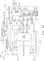
- FIG. 10 illustrates a surgical hub 206 comprising a plurality of modules coupled to the modular control tower 236.
- the modular control tower 236 comprises a modular communication hub 203, e.g., a network connectivity device, and a computer system 210 to provide local processing, visualization, and imaging, for example.
- the modular communication hub 203 is connected in a tiered configuration to expand the number of modules (e.g., devices) that may be connected to the modular communication hub 203 and transfer data associated with the modules to the computer system 210, cloud computing resources, or both.
- each of the network hubs/switches in the modular communication hub 203 includes three downstream ports and one upstream port.
- the upstream network hub/switch is connected to a processor to provide a communication connection to the cloud computing resources and a local display 217. Communication to the cloud 204 is made either through a wired or a wireless communication channel.
- the surgical hub 206 employs a non-contact sensor module 242 to measure the dimensions of the operating theater and generate a map of the surgical theater using either ultrasonic or laser-type non-contact measurement devices.
- An ultrasound-based non-contact sensor module scans the operating theater by transmitting a burst of ultrasound and receiving the echo when it bounces off the perimeter walls of an operating theater as described under the heading "Surgical Hub Spatial Awareness Within an Operating Room” in U.S. Provisional Patent Application Serial No. 62/611,341 , titled INTERACTIVE SURGICAL PLATFORM, filed December 28, 2017, in which the sensor module is configured to determine the size of the operating theater and to adjust Bluetooth-pairing distance limits.
- a laser-based non-contact sensor module scans the operating theater by transmitting laser light pulses, receiving laser light pulses that bounce off the perimeter walls of the operating theater, and comparing the phase of the transmitted pulse to the received pulse to determine the size of the operating theater and to adjust Bluetooth pairing distance limits, for example.
- the computer system 210 comprises a processor 244 and a network interface 245.
- the processor 244 is coupled to a communication module 247, storage 248, memory 249, non-volatile memory 250, and input/output interface 251 via a system bus.
- the system bus is any of several types of bus structure(s) including the memory bus or memory controller, a peripheral bus or external bus, and/or a local bus using any variety of available bus architectures including, but not limited to, 9-bit bus, Industrial Standard Architecture (ISA), Micro-Charmel Architecture (MSA), Extended ISA (EISA), Intelligent Drive Electronics (IDE), VESA Local Bus (VLB), Peripheral Component Interconnect (PCI), USB, Advanced Graphics Port (AGP), Personal Computer Memory Card International Association bus (PCMCIA), Small Computer Systems Interface (SCSI), or any other proprietary bus.
- ISA Industrial Standard Architecture
- MSA Micro-Charmel Architecture
- EISA Extended ISA
- IDE Intelligent Drive Electronics
- VLB VESA Local Bus
- PCI Perip
- the processor 244 is any single-core or multicore processor such as those known under the trade name ARM Cortex by Texas Instruments.
- the processor may be an LM4F230H5QR ARM Cortex-M4F Processor Core, available from Texas Instruments, for example, comprising an on-chip memory of 256 KB single-cycle flash memory, or other non-volatile memory, up to 40 MHz, a prefetch buffer to improve performance above 40 MHz, a 32 KB single-cycle serial random access memory (SRAM), an internal read-only memory (ROM) loaded with StellarisWare® software, a 2 KB electrically erasable programmable read-only memory (EEPROM), and/or one or more pulse width modulation (PWM) modules, one or more quadrature encoder inputs (QEI) analogs, one or more 12-bit analog-to-digital converters (ADCs) with 12 analog input channels, details of which are available for the product datasheet.
- QEI quadrature encoder inputs
- the processor 244 comprises a safety controller comprising two controller-based families such as TMS570 and RM4x, known under the trade name Hercules ARM Cortex R4, also by Texas Instruments.
- the safety controller is configured specifically for IEC 61508 and ISO 26262 safety critical applications, among others, to provide advanced integrated safety features while delivering scalable performance, connectivity, and memory options.
- the system memory includes volatile memory and non-volatile memory.
- the basic input/output system (BIOS) containing the basic routines to transfer information between elements within the computer system, such as during start-up, is stored in non-volatile memory.
- the non-volatile memory can include ROM, programmable ROM (PROM), electrically programmable ROM (EPROM), EEPROM, or flash memory.
- Volatile memory includes random-access memory (RAM), which acts as external cache memory.
- RAM is available in many forms such as SRAM, dynamic RAM (DRAM), synchronous DRAM (SDRAM), double data rate SDRAM (DDR SDRAM), enhanced SDRAM (ESDRAM), Synchlink DRAM (SLDRAM), and direct Rambus RAM (DRRAM).
- the computer system 210 also includes removable/non-removable, volatile/non-volatile computer storage media, such as for example disk storage.
- the disk storage includes, but is not limited to, devices like a magnetic disk drive, floppy disk drive, tape drive, Jaz drive, Zip drive, LS-60 drive, flash memory card, or memory stick.
- the disk storage can include storage media separately or in combination with other storage media including, but not limited to, an optical disc drive such as a compact disc ROM device (CD-ROM), compact disc recordable drive (CD-R Drive), compact disc rewritable drive (CD-RW Drive), or a digital versatile disc ROM drive (DVD-ROM).
- CD-ROM compact disc ROM
- CD-R Drive compact disc recordable drive
- CD-RW Drive compact disc rewritable drive
- DVD-ROM digital versatile disc ROM drive
- a removable or non-removable interface may be employed.
- the computer system 210 includes software that acts as an intermediary between users and the basic computer resources described in a suitable operating environment.
- Such software includes an operating system.
- the operating system which can be stored on the disk storage, acts to control and allocate resources of the computer system.
- System applications take advantage of the management of resources by the operating system through program modules and program data stored either in the system memory or on the disk storage. It is to be appreciated that various components described herein can be implemented with various operating systems or combinations of operating systems.
- a user enters commands or information into the computer system 210 through input device(s) coupled to the I/O interface 251.
- the input devices include, but are not limited to, a pointing device such as a mouse, trackball, stylus, touch pad, keyboard, microphone, joystick, game pad, satellite dish, scanner, TV tuner card, digital camera, digital video camera, web camera, and the like.
- These and other input devices connect to the processor through the system bus via interface port(s).
- the interface port(s) include, for example, a serial port, a parallel port, a game port, and a USB.
- the output device(s) use some of the same types of ports as input device(s).
- a USB port is used to provide input to the computer system and to output information from the computer system to an output device.
- An output adapter is provided to illustrate that there are some output devices like monitors, displays, speakers, and printers, among other output devices that require special adapters.
- the output adapters include, by way of illustration and not limitation, video and sound cards that provide a means of connection between the output device and the system bus. It should be noted that other devices and/or systems of devices, such as remote computer(s), provide both input and output capabilities.
- the computer system 210 operates in a networked environment using logical connections to one or more remote computers, such as cloud computer(s), or local computers.
- the remote cloud computer(s) can be a personal computer, server, router, network PC, workstation, microprocessor-based appliance, peer device, or other common network node, and the like, and typically includes many or all of the elements described relative to the computer system. For purposes of brevity, only a memory storage device is illustrated with the remote computer(s).
- the remote computer(s) is logically connected to the computer system through a network interface and then physically connected via a communication connection.
- the network interface encompasses communication networks such as local area networks (LANs) and wide area networks (WANs).
- LAN technologies include Fiber Distributed Data Interface (FDDI), Copper Distributed Data Interface (CDDI), Ethernet/IEEE 802.3, Token Ring/IEEE 802.5 and the like.
- WAN technologies include, but are not limited to, point-to-point links, circuit-switching networks like Integrated Services Digital Networks (ISDN) and variations thereon, packet-switching networks, and Digital Subscriber Lines (DSL).
- ISDN Integrated Services Digital Networks
- DSL Digital Subscriber Lines
- the computer system 210 of FIG. 10 , the imaging module 238 and/or visualization system 208, and/or the processor module 232 of FIGS. 9-10 comprises an image processor, image processing engine, media processor, or any specialized digital signal processor (DSP) used for the processing of digital images.
- the image processor employs parallel computing with single instruction, multiple data (SIMD) or multiple instruction, multiple data (MIMD) technologies to increase speed and efficiency.
- SIMD single instruction, multiple data
- MIMD multiple instruction, multiple data
- the digital image processing engine can perform a range of tasks.
- the image processor may be a system on a chip with multicore processor architecture.
- the communication connection(s) refers to the hardware/software employed to connect the network interface to the bus. While the communication connection is shown for illustrative clarity inside the computer system, it can also be external to the computer system 210.
- the hardware/software necessary for connection to the network interface includes, for illustrative purposes only, internal and external technologies such as modems, including regular telephone-grade modems, cable modems, and DSL modems, ISDN adapters, and Ethernet cards.
- FIG. 11 illustrates a functional block diagram of a USB network hub 300 device.
- the USB network hub device 300 employs a TUSB2036 integrated circuit hub by Texas Instruments.
- the USB network hub 300 is a CMOS device that provides an upstream USB transceiver port 302 and up to three downstream USB transceiver ports 304, 306, 308 in compliance with the USB 2.0 specification.
- the upstream USB transceiver port 302 is a differential root data port comprising a differential data minus (DM0) input paired with a differential data plus (DP0) input.
- the three downstream USB transceiver ports 304, 306, 308 are differential data ports where each port includes differential data plus (DP1-DP3) outputs paired with differential data minus (DM1-DM3) outputs.
- the USB network hub 300 device is implemented with a digital state machine instead of a microcontroller, and no firmware programming is required. Fully compliant USB transceivers are integrated into the circuit for the upstream USB transceiver port 302 and all downstream USB transceiver ports 304, 306, 308.
- the downstream USB transceiver ports 304, 306, 308 support both full-speed and low-speed devices by automatically setting the slew rate according to the speed of the device attached to the ports.
- the USB network hub 300 device may be configured either in bus-powered or self-powered mode and includes a hub power logic 312 to manage power.
- the USB network hub 300 device includes a serial interface engine 310 (SIE).
- SIE 310 is the front end of the USB network hub 300 hardware and handles most of the protocol described in chapter 8 of the USB specification.
- the SIE 310 typically comprehends signaling up to the transaction level.
- the functions that it handles include: packet recognition, transaction sequencing, SOP, EOP, RESET, and RESUME signal detection/generation, clock/data separation, non-return-to-zero invert (NRZI) data encoding/decoding and bit-stuffing, CRC generation and checking (token and data), packet ID (PID) generation and checking/decoding, and/or serial-parallel/parallel-serial conversion.
- NRZI non-return-to-zero invert
- the 310 receives a clock input 314 and is coupled to a suspend/resume logic and frame timer 316 circuit and a hub repeater circuit 318 to control communication between the upstream USB transceiver port 302 and the downstream USB transceiver ports 304, 306, 308 through port logic circuits 320, 322, 324.
- the SIE 310 is coupled to a command decoder 326 via interface logic to control commands from a serial EEPROM via a serial EEPROM interface 330.
- the USB network hub 300 connects 127 functions configured in up to six logical layers (tiers) to a single computer. Further, the USB network hub 300 connects to all peripherals using a standardized four-wire cable that provides both communication and power distribution.
- the power configurations are bus-powered and self-powered modes.
- the USB network hub 300 is configured to support four modes of power management: a bus-powered hub, with either individual-port power management or ganged-port power management, and the self-powered hub, with either individual-port power management or ganged-port power management.
- the upstream USB transceiver port 302 is plugged into a USB host controller, and the downstream USB transceiver ports 304, 306, 308 are exposed for connecting USB compatible devices, and so forth.
- FIG. 12 illustrates a logic diagram of a control system 470 of a surgical instrument or tool.
- the system 470 comprises a control circuit.
- the control circuit includes a microcontroller 461 comprising a processor 462 and a memory 468.
- One or more of sensors 472, 474, 476 for example, provide real-time feedback to the processor 462.
- a motor 482, driven by a motor driver 492, operably couples a longitudinally movable displacement member to drive the I-beam knife element.
- a tracking system 480 is configured to determine the position of the longitudinally movable displacement member.
- the position information is provided to the processor 462, which is programmed or configured to determine the position of the longitudinally movable drive member as well as the position of a firing member, firing bar, and I-beam knife element.
- a display 473 displays a variety of operating conditions of the instruments and includes touch screen functionality for data input. Information displayed on the display 473 is overlaid with images acquired via endoscopic imaging modules.
- the microcontroller 461 may be any single-core or multicore processor such as those known under the trade name ARM Cortex by Texas Instruments.
- the main microcontroller 461 may be an LM4F230H5QR ARM Cortex-M4F Processor Core, available from Texas Instruments, for example, comprising an on-chip memory of 256 KB single-cycle flash memory, or other non-volatile memory, up to 40 MHz, a prefetch buffer to improve performance above 40 MHz, a 32 KB single-cycle SRAM, and internal ROM loaded with StellarisWare® software, a 2 KB EEPROM, one or more PWM modules, one or more QEI analogs, and/or one or more 12-bit ADCs with 12 analog input channels, details of which are available for the product datasheet.
- the microcontroller 461 comprises a safety controller comprising two controller-based families such as TMS570 and RM4x, known under the trade name Hercules ARM Cortex R4, also by Texas Instruments.
- the safety controller is configured specifically for IEC 61508 and ISO 26262 safety critical applications, among others, to provide advanced integrated safety features while delivering scalable performance, connectivity, and memory options.
- the microcontroller 461 is programmed to perform various functions such as precise control over the speed and position of the knife and articulation systems.
- the microcontroller 461 includes a processor 462 and a memory 468.
- the electric motor 482 may be a brushed direct current (DC) motor with a gearbox and mechanical links to an articulation or knife system.
- a motor driver 492 is an A3941 available from Allegro Microsystems, Inc. Other motor drivers may be readily substituted for use in the tracking system 480 comprising an absolute positioning system. A detailed description of an absolute positioning system is described in U.S. Patent Application Publication No. 2017/0296213 , titled SYSTEMS AND METHODS FOR CONTROLLING A SURGICAL STAPLING AND CUTTING INSTRUMENT, which published on October 19, 2017.
- the microcontroller 461 is programmed to provide precise control over the speed and position of displacement members and articulation systems.
- the microcontroller 461 is configured to compute a response in the software of the microcontroller 461.
- the computed response is compared to a measured response of the actual system to obtain an "observed" response, which is used for actual feedback decisions.
- the observed response is a favorable, tuned value that balances the smooth, continuous nature of the simulated response with the measured response, which detects outside influences on the system.
- the motor 482 is controlled by the motor driver 492 and is employed by the firing system of the surgical instrument or tool.
- the motor 482 is a brushed DC driving motor having a maximum rotational speed of approximately 25,000 RPM.
- the motor 482 includes a brushless motor, a cordless motor, a synchronous motor, a stepper motor, or any other suitable electric motor.
- the motor driver 492 comprises an H-bridge driver comprising field-effect transistors (FETs), for example.
- FETs field-effect transistors
- the motor 482 is powered by a power assembly releasably mounted to the handle assembly or tool housing for supplying control power to the surgical instrument or tool.
- the power assembly comprises a battery which includes a number of battery cells connected in series that can be used as the power source to power the surgical instrument or tool. In certain circumstances, the battery cells of the power assembly are replaceable and/or rechargeable. In at least one example, the battery cells can be lithium-ion batteries which are couplable to and separable from the power
- the motor driver 492 may be an A3941 available from Allegro Microsystems, Inc.
- the A3941 492 is a full-bridge controller for use with external N-channel power metal-oxide semiconductor field-effect transistors (MOSFETs) specifically designed for inductive loads, such as brush DC motors.
- the driver 492 comprises a unique charge pump regulator that provides full (>10 V) gate drive for battery voltages down to 7 V and allows the A3941 to operate with a reduced gate drive, down to 5.5 V.
- a bootstrap capacitor is employed to provide the above battery supply voltage required for N-channel MOSFETs.
- An internal charge pump for the high-side drive allows DC (100% duty cycle) operation.
- the full bridge is driven in fast or slow decay modes using diode or synchronous rectification.
- current recirculation can be through the high-side or the lowside FETs.
- the power FETs are protected from shoot-through by resistor-adjustable dead time.
- Integrated diagnostics provide indications of undervoltage, overtemperature, and power bridge faults and are configured to protect the power MOSFETs under most short circuit conditions.
- Other motor drivers are readily substituted for use in the tracking system 480 comprising an absolute positioning system.
- the tracking system 480 comprises a controlled motor drive circuit arrangement comprising a position sensor 472.
- the position sensor 472 for an absolute positioning system provides a unique position signal corresponding to the location of a displacement member.
- the displacement member represents a longitudinally movable drive member comprising a rack of drive teeth for meshing engagement with a corresponding drive gear of a gear reducer assembly.
- the displacement member represents the firing member, which could be adapted and configured to include a rack of drive teeth.
- the displacement member represents a firing bar or the I-beam, each of which can be adapted and configured to include a rack of drive teeth.
- the term displacement member is used generically to refer to any movable member of the surgical instrument or tool such as the drive member, the firing member, the firing bar, the I-beam, or any element that can be displaced.
- the longitudinally movable drive member is coupled to the firing member, the firing bar, and the I-beam. Accordingly, the absolute positioning system can, in effect, track the linear displacement of the I-beam by tracking the linear displacement of the longitudinally movable drive member.
- the displacement member is coupled to any position sensor 472 suitable for measuring linear displacement.
- the longitudinally movable drive member, the firing member, the firing bar, or the I-beam, or combinations thereof, are coupled to any suitable linear displacement sensor.
- Linear displacement sensors include contact or non-contact displacement sensors.
- Linear displacement sensors comprise linear variable differential transformers (LVDT), differential variable reluctance transducers (DVRT), a slide potentiometer, a magnetic sensing system comprising a movable magnet and a series of linearly arranged Hall effect sensors, a magnetic sensing system comprising a fixed magnet and a series of movable, linearly arranged Hall effect sensors, an optical sensing system comprising a movable light source and a series of linearly arranged photo diodes or photo detectors, an optical sensing system comprising a fixed light source and a series of movable linearly, arranged photo diodes or photo detectors, or any combination thereof.
- LVDT linear variable differential transformers
- DVRT differential variable reluctance transducers
- slide potentiometer a magnetic sensing system comprising a movable magnet and a series of linearly arranged Hall effect sensors
- a magnetic sensing system comprising a fixed magnet and a series of movable, linearly arranged Hall effect sensors
- the electric motor 482 can include a rotatable shaft that operably interfaces with a gear assembly that is mounted in meshing engagement with a set, or rack, of drive teeth on the displacement member.
- a sensor element is operably coupled to a gear assembly such that a single revolution of the position sensor 472 element corresponds to some linear longitudinal translation of the displacement member.
- An arrangement of gearing and sensors is connected to the linear actuator, via a rack and pinion arrangement, or a rotary actuator, via a spur gear or other connection.
- a power source supplies power to the absolute positioning system and an output indicator may display the output of the absolute positioning system.
- the displacement member represents the longitudinally movable drive member comprising a rack of drive teeth formed thereon for meshing engagement with a corresponding drive gear of the gear reducer assembly.
- the displacement member represents the longitudinally movable firing member, firing bar, I-beam, or combinations thereof.
- a single revolution of the sensor element associated with the position sensor 472 is equivalent to a longitudinal linear displacement d1 of the of the displacement member, where d1 is the longitudinal linear distance that the displacement member moves from point "a" to point "b” after a single revolution of the sensor element coupled to the displacement member.
- the sensor arrangement may be connected via a gear reduction that results in the position sensor 472 completing one or more revolutions for the full stroke of the displacement member.
- the position sensor 472 may complete multiple revolutions for the full stroke of the displacement member.
- a series of switches where n is an integer greater than one, is employed alone or in combination with a gear reduction to provide a unique position signal for more than one revolution of the position sensor 472.
- the state of the switches are fed back to the microcontroller 461 that applies logic to determine a unique position signal corresponding to the longitudinal linear displacement d1 + d2 + ... dn of the displacement member.
- the output of the position sensor 472 is provided to the microcontroller 461.
- the position sensor 472 of the sensor arrangement comprises a magnetic sensor, an analog rotary sensor like a potentiometer, or an array of analog Hall-effect elements, which output a unique combination of position signals or values.
- the position sensor 472 comprise a any number of magnetic sensing elements, such as, for example, magnetic sensors classified according to whether they measure the total magnetic field or the vector components of the magnetic field.
- the techniques used to produce both types of magnetic sensors encompass many aspects of physics and electronics.
- the technologies used for magnetic field sensing include search coil, fluxgate, optically pumped, nuclear precession, SQUID, Hall-effect, anisotropic magnetoresistance, giant magnetoresistance, magnetic tunnel junctions, giant magnetoimpedance, magnetostrictive/piezoelectric composites, magnetodiode, magnetotransistor, fiber-optic, magneto-optic, and microelectromechanical systems-based magnetic sensors, among others.
- the position sensor 472 for the tracking system 480 comprising an absolute positioning system comprises a magnetic rotary absolute positioning system.
- the position sensor 472 may be implemented as an AS5055EQFT single-chip magnetic rotary position sensor available from Austria Microsystems, AG.
- the position sensor 472 is interfaced with the microcontroller 461 to provide an absolute positioning system.
- the position sensor 472 is a low-voltage and low-power component and includes four Hall-effect elements in an area of the position sensor 472 that is located above a magnet.
- a high-resolution ADC and a smart power management controller are also provided on the chip.
- a coordinate rotation digital computer (CORDIC) processor also known as the digit-by-digit method and Volder's algorithm, is provided to implement a simple and efficient algorithm to calculate hyperbolic and trigonometric functions that require only addition, subtraction, bitshift, and table lookup operations.
- the angle position, alarm bits, and magnetic field information are transmitted over a standard serial communication interface, such as a serial peripheral interface (SPI) interface, to the microcontroller 461.
- SPI serial peripheral interface
- the position sensor 472 provides 12 or 14 bits of resolution.
- the position sensor 472 may be an AS5055 chip provided in a small QFN 16-pin 4x4x0.85mm package.
- the tracking system 480 comprising an absolute positioning system comprises and/or is programmed to implement a feedback controller, such as a PID, state feedback, and adaptive controller.
- a power source converts the signal from the feedback controller into a physical input to the system: in this case the voltage.
- Other examples include a PWM of the voltage, current, and force.
- Other sensor(s) may be provided to measure physical parameters of the physical system in addition to the position measured by the position sensor 472.
- the other sensor(s) can include sensor arrangements such as those described in U.S. Patent No. 9,345,481 , titled STAPLE CARTRIDGE TISSUE THICKNESS SENSOR SYSTEM, which issued on May 24, 2016; U.S. Patent Application Publication No.
- an absolute positioning system is coupled to a digital data acquisition system where the output of the absolute positioning system will have a finite resolution and sampling frequency.
- the absolute positioning system comprises a compare-and-combine circuit to combine a computed response with a measured response using algorithms, such as a weighted average and a theoretical control loop, that drive the computed response towards the measured response.
- the computed response of the physical system takes into account properties like mass, inertial, viscous friction, inductance resistance, etc., to predict what the states and outputs of the physical system will be by knowing the input.
- the absolute positioning system provides an absolute position of the displacement member upon power-up of the instrument, without retracting or advancing the displacement member to a reset (zero or home) position as may be required with conventional rotary encoders that merely count the number of steps forwards or backwards that the motor 482 has taken to infer the position of a device actuator, drive bar, knife, or the like.
- a sensor 474 such as, for example, a strain gauge or a micro-strain gauge, is configured to measure one or more parameters of the end effector, such as, for example, the amplitude of the strain exerted on the anvil during a clamping operation, which is indicative of the closure forces applied to the anvil.
- the measured strain is converted to a digital signal and provided to the processor 462.
- a sensor 476 such as, for example, a load sensor, measures the closure force applied by the closure drive system to the anvil.
- the sensor 476 such as, for example, a load sensor, can measure the firing force applied to an I-beam in a firing stroke of the surgical instrument or tool.
- the I-beam is configured to engage a wedge sled, which is configured to upwardly cam staple drivers to force out staples into deforming contact with an anvil.
- the I-beam also includes a sharpened cutting edge that is used to sever tissue as the I-beam is advanced distally by the firing bar.
- a current sensor 478 is employed to measure the current drawn by the motor 482. The force required to advance the firing member corresponds to the current drawn by the motor 482, for example. The measured force is converted to a digital signal and provided to the processor 462.
- the strain gauge sensor 474 is used to measure the force applied to the tissue by the end effector.
- a strain gauge is coupled to the end effector to measure the force on the tissue being treated by the end effector.
- a system for measuring forces applied to the tissue grasped by the end effector comprises a strain gauge sensor 474, such as, for example, a micro-strain gauge, that is configured to measure one or more parameters of the end effector, for example.
- the strain gauge sensor 474 measures the amplitude or magnitude of the strain exerted on a jaw member of an end effector during a clamping operation, which is indicative of the tissue compression.
- the measured strain is converted to a digital signal and provided to a processor 462 of the microcontroller 461.
- a load sensor 476 measures the force used to operate the knife element, for example, to cut the tissue captured between the anvil and the staple cartridge.
- a magnetic field sensor is employed to measure the thickness of the captured tissue. The measurement of the magnetic field sensor also may be converted to a digital signal and provided to the processor 462.
- a memory 468 stores a technique, an equation, and/or a lookup table which is employed by the microcontroller 461 in the assessment.
- the control system 470 of the surgical instrument or tool also comprises wired or wireless communication circuits to communicate with the modular communication hub as shown in FIGS. 8-11 .
- FIG. 13 illustrates a control circuit 500 configured to control aspects of the surgical instrument or tool.
- the control circuit 500 is configured to implement various processes described herein.
- the control circuit 500 comprises a microcontroller comprising one or more processors 502 (e.g., microprocessor, microcontroller) coupled to at least one memory circuit 504.
- the memory circuit 504 stores machine-executable instructions that, when executed by the processor 502, cause the processor 502 to execute machine instructions to implement various processes described herein.
- the processor 502 is any one of a number of single-core or multicore processors known in the art.
- the memory circuit 504 comprises volatile and non-volatile storage media.
- the processor 502 includes an instruction processing unit 506 and an arithmetic unit 508.
- the instruction processing unit is configured to receive instructions from the memory circuit 504 of this disclosure.
- FIG. 14 illustrates a combinational logic circuit 510 configured to control aspects of the surgical instrument or tool.
- the combinational logic circuit 510 can be configured to implement various processes described herein.
- the combinational logic circuit 510 comprises a finite state machine comprising a combinational logic 512 configured to receive data associated with the surgical instrument or tool at an input 514, process the data by the combinational logic 512, and provide an output 516.
- FIG. 15 illustrates a sequential logic circuit 520 configured to control aspects of the surgical instrument or tool.
- the sequential logic circuit 520 or the combinational logic 522 is configured to implement various processes described herein.
- the sequential logic circuit 520 comprises a finite state machine.
- the sequential logic circuit 520 comprises a combinational logic 522, at least one memory circuit 524, and a clock 529, for example.
- the at least one memory circuit 524 stores a current state of the finite state machine.
- the sequential logic circuit 520 is synchronous or asynchronous.
- the combinational logic 522 is configured to receive data associated with the surgical instrument or tool from an input 526, process the data by the combinational logic 522, and provide an output 528.
- the circuit comprises a combination of a processor (e.g., processor 502, FIG. 13 ) and a finite state machine to implement various processes herein.
- the finite state machine comprises a combination of a combinational logic circuit (e.g., combinational logic circuit 510, FIG.
- FIG. 16 illustrates a surgical instrument or tool comprising a plurality of motors which are activated to perform various functions.
- a first motor is activated to perform a first function
- a second motor is activated to perform a second function
- a third motor is activated to perform a third function
- a fourth motor is activated to perform a fourth function, and so on.
- the plurality of motors of robotic surgical instrument 600 are individually activated to cause firing, closure, and/or articulation motions in the end effector.
- the firing, closure, and/or articulation motions are transmitted to the end effector through a shaft assembly, for example.
- the surgical instrument system or tool includes a firing motor 602.
- the firing motor 602 is operably coupled to a firing motor drive assembly 604 which is configured to transmit firing motions, generated by the motor 602 to the end effector, in particular to displace the I-beam element.
- the firing motions generated by the motor 602 cause the staples to be deployed from the staple cartridge into tissue captured by the end effector and/or the cutting edge of the I-beam element to be advanced to cut the captured tissue, for example.
- the I-beam element is retracted by reversing the direction of the motor 602.
- the surgical instrument or tool includes a closure motor 603.
- the closure motor 603 is operably coupled to a closure motor drive assembly 605 which is configured to transmit closure motions, generated by the motor 603 to the end effector, in particular to displace a closure tube to close the anvil and compress tissue between the anvil and the staple cartridge.
- the closure motions cause the end effector to transition from an open configuration to an approximated configuration to capture tissue, for example.
- the end effector is transitioned to an open position by reversing the direction of the motor 603.
- the surgical instrument or tool includes one or more articulation motors 606a, 606b, for example.
- the motors 606a, 606b are operably coupled to respective articulation motor drive assemblies 608a, 608b, which are configured to transmit articulation motions generated by the motors 606a, 606b to the end effector.
- the articulation motions causes the end effector to articulate relative to the shaft, for example.
- the surgical instrument or tool includes a plurality of motors which are configured to perform various independent functions.
- the plurality of motors of the surgical instrument or tool are individually or separately activated to perform one or more functions while the other motors remain inactive.
- the articulation motors 606a, 606b are activated to cause the end effector to be articulated while the firing motor 602 remains inactive.
- the firing motor 602 is activated to fire the plurality of staples, and/or to advance the cutting edge, while the articulation motor 606 remains inactive.
- the closure motor 603 is activated simultaneously with the firing motor 602 to cause the closure tube and the I-beam element to advance distally as described in more detail hereinbelow.
- the surgical instrument or tool includes a common control module 610 which is employed with a plurality of motors of the surgical instrument or tool.
- the common control module 610 accommodates one of the plurality of motors at a time.
- the common control module 610 is couplable to and separable from the plurality of motors of the robotic surgical instrument individually.
- a plurality of the motors of the surgical instrument or tool shares one or more common control modules such as the common control module 610.
- a plurality of motors of the surgical instrument or tool are individually and selectively engaged with the common control module 610.
- the common control module 610 is selectively switched from interfacing with one of a plurality of motors of the surgical instrument or tool to interfacing with another one of the plurality of motors of the surgical instrument or tool.
- the common control module 610 is selectively switched between operable engagement with the articulation motors 606a, 606b and operable engagement with either the firing motor 602 or the closure motor 603. As illustrated in FIG. 16 , a switch 614 is moved or transitioned between a plurality of positions and/or states.
- the switch 614 electrically couples the common control module 610 to the firing motor 602; in a second position 617, the switch 614 electrically couples the common control module 610 to the closure motor 603; in a third position 618a, the switch 614 electrically couples the common control module 610 to the first articulation motor 606a; and in a fourth position 618b, the switch 614 electrically couples the common control module 610 to the second articulation motor 606b, for example.
- separate common control modules 610 are electrically coupled to the firing motor 602, the closure motor 603, and the articulations motor 606a, 606b at the same time.
- the switch 614 may be a mechanical switch, an electromechanical switch, a solid-state switch, or any suitable switching mechanism.
- Each of the motors 602, 603, 606a, 606b comprises a torque sensor to measure the output torque on the shaft of the motor.
- the force on an end effector is sensed in any conventional manner, such as by force sensors on the outer sides of the jaws or by a torque sensor for the motor actuating the jaws.
- the common control module 610 comprises a motor driver 626 which comprises one or more H-Bridge FETs.
- the motor driver 626 modulates the power transmitted from a power source 628 to a motor coupled to the common control module 610 based on input from a microcontroller 620 (the "controller"), for example.
- the microcontroller 620 is employed to determine the current drawn by the motor while the motor is coupled to the common control module 610, as described above.
- the microcontroller 620 includes a microprocessor 622 (the "processor") and one or more non-transitory computer-readable mediums or memory units 624 (the “memory”).
- the memory 624 stores various program instructions, which when executed cause the processor 622 to perform a plurality of functions and/or calculations described herein.
- One or more of the memory units 624 is coupled to the processor 622.
- the power source 628 is employed to supply power to the microcontroller 620.
- the power source 628 may comprise a battery (or "battery pack” or “power pack”), such as a lithium-ion battery, for example.
- the battery pack is configured to be releasably mounted to a handle for supplying power to the surgical instrument 600.
- a number of battery cells connected in series is used as the power source 628.
- the power source 628 may be replaceable and/or rechargeable.
- the processor 622 controls the motor driver 626 to control the position, direction of rotation, and/or velocity of a motor that is coupled to the common control module 610.
- the processor 622 signals the motor driver 626 to stop and/or disable a motor that is coupled to the common control module 610.
- processor includes any suitable microprocessor, microcontroller, or other basic computing device that incorporates the functions of a computer's central processing unit (CPU) on an integrated circuit or, at most, a few integrated circuits.
- the processor is a multipurpose, programmable device that accepts digital data as input, processes it according to instructions stored in its memory, and provides results as output. It is an example of sequential digital logic, as it has internal memory. Processors operate on numbers and symbols represented in the binary numeral system.
- the processor 622 may be any single-core or multicore processor such as those known under the trade name ARM Cortex by Texas Instruments.
- the microcontroller 620 may be an LM 4F230H5QR, available from Texas Instruments.
- the Texas Instruments LM4F230H5QR is an ARM Cortex-M4F Processor Core comprising an on-chip memory of 256 KB single-cycle flash memory, or other non-volatile memory, up to 40 MHz, a prefetch buffer to improve performance above 40 MHz, a 32 KB single-cycle SRAM, an internal ROM loaded with StellarisWare® software, a 2 KB EEPROM, one or more PWM modules, one or more QEI analogs, one or more 12-bit ADCs with 12 analog input channels, among other features that are readily available for the product datasheet.
- Other microcontrollers may be readily substituted for use with the module 4410. Accordingly, the present disclosure should not be limited in this context.
- the memory 624 includes program instructions for controlling each of the motors of the surgical instrument 600 that are couplable to the common control module 610.
- the memory 624 includes program instructions for controlling the firing motor 602, the closure motor 603, and the articulation motors 606a, 606b. Such program instructions cause the processor 622 to control the firing, closure, and articulation functions in accordance with inputs from algorithms or control programs of the surgical instrument or tool.
- One or more mechanisms and/or sensors such as sensors 630 are employed to alert the processor 622 to the program instructions that should be used in a particular setting.
- the sensors 630 alert the processor 622 to use the program instructions associated with firing, closing, and articulating the end effector.
- the sensors 630 comprise position sensors which are be employed to sense the position of the switch 614.
- the processor 622 uses the program instructions associated with firing the I-beam of the end effector upon detecting, through the sensors 630 , that the switch 614 is in the first position 616; the processor 622 uses the program instructions associated with closing the anvil upon detecting, through the sensors 630 , that the switch 614 is in the second position 617; and the processor 622 uses the program instructions associated with articulating the end effector upon detecting, through the sensors 630 , that the switch 614 is in the third or fourth position 618a, 618b.
- FIG. 17 is a schematic diagram of a robotic surgical instrument 700 configured to operate a surgical tool described herein .
- the robotic surgical instrument 700 is programmed or configured to control distal/proximal translation of a displacement member, distal/proximal displacement of a closure tube, shaft rotation, and articulation, either with single or multiple articulation drive links.
- the surgical instrument 700 is programmed or configured to individually control a firing member, a closure member, a shaft member, and/or one or more articulation members.
- the surgical instrument 700 comprises a control circuit 710 configured to control motor-driven firing members, closure members, shaft members, and/or one or more articulation members.
- the robotic surgical instrument 700 comprises a control circuit 710 configured to control an anvil 716 and an I-beam 714 (including a sharp cutting edge) portion of an end effector 702, a removable staple cartridge 718, a shaft 740, and one or more articulation members 742a, 742b via a plurality of motors 704a-704e.
- a position sensor 734 is configured to provide position feedback of the I-beam 714 to the control circuit 710.
- Other sensors 738 are configured to provide feedback to the control circuit 710.
- a timer/counter 731 provides timing and counting information to the control circuit 710.
- An energy source 712 is provided to operate the motors 704a-704e, and a current sensor 736 provides motor current feedback to the control circuit 710.
- the motors 704a-704e are operated individually by the control circuit 710 in a open-loop or closed-loop feedback control.
- the control circuit 710 comprises one or more microcontrollers, microprocessors, or other suitable processors for executing instructions that cause the processor or processors to perform one or more tasks.
- a timer/counter 731 provides an output signal, such as the elapsed time or a digital count, to the control circuit 710 to correlate the position of the I-beam 714 as determined by the position sensor 734 with the output of the timer/counter 731 such that the control circuit 710 can determine the position of the I-beam 714 at a specific time (t) relative to a starting position or the time (t) when the I-beam 714 is at a specific position relative to a starting position.
- the timer/counter 731 is configured to measure elapsed time, count external events, or time external events.
- the control circuit 710 is programmed to control functions of the end effector 702 based on one or more tissue conditions.
- the control circuit 710 is programmed to sense tissue conditions, such as thickness, either directly or indirectly, as described herein.
- the control circuit 710 is programmed to select a firing control program or closure control program based on tissue conditions.
- a firing control program describes the distal motion of the displacement member. Different firing control programs are selected to better treat different tissue conditions. For example, when thicker tissue is present, the control circuit 710 is programmed to translate the displacement member at a lower velocity and/or with lower power. When thinner tissue is present, the control circuit 710 is programmed to translate the displacement member at a higher velocity and/or with higher power.
- a closure control program controls the closure force applied to the tissue by the anvil 716. Other control programs control the rotation of the shaft 740 and the articulation members 742a, 742b.
- the control circuit 710 generates motor set point signals.
- the motor set point signals are provided to various motor controllers 708a-708e.
- the motor controllers 708a-708e comprise one or more circuits configured to provide motor drive signals to the motors 704a-704e to drive the motors 704a-704e as described herein.
- the motors 704a-704e may be brushed DC electric motors.
- the velocity of the motors 704a-704e are proportional to the respective motor drive signals.
- the motors 704a-704e may be brushless DC electric motors, and the respective motor drive signals may comprise a PWM signal provided to one or more stator windings of the motors 704a-704e.
- the motor controllers 708a-708e may be omitted and the control circuit 710 may generate the motor drive signals directly.
- the control circuit 710 initially operates each of the motors 704a-704e in an open-loop configuration for a first open-loop portion of a stroke of the displacement member. Based on the response of the robotic surgical instrument 700 during the open-loop portion of the stroke, the control circuit 710 selects a firing control program in a closed-loop configuration.
- the response of the instrument includes a translation distance of the displacement member during the open-loop portion, a time elapsed during the open-loop portion, the energy provided to one of the motors 704a-704e during the open-loop portion, a sum of pulse widths of a motor drive signal, etc.
- the control circuit 710 implements the selected firing control program for a second portion of the displacement member stroke.
- control circuit 710 modulates one of the motors 704a-704e based on translation data describing a position of the displacement member in a closed-loop manner to translate the displacement member at a constant velocity.
- the motors 704a-704e receive power from an energy source 712.
- the energy source 712 is a DC power supply driven by a main alternating current power source, a battery, a super capacitor, or any other suitable energy source.
- the motors 704a-704e are mechanically coupled to individual movable mechanical elements such as the I-beam 714, anvil 716, shaft 740, articulation 742a, and articulation 742b via respective transmissions 706a-706e.
- the transmissions 706a-706e include one or more gears or other linkage components to couple the motors 704a-704e to movable mechanical elements.
- a position sensor 734 senses a position of the I-beam 714.
- the position sensor 734 includes any type of sensor that is capable of generating position data that indicate a position of the I-beam 714.
- the position sensor 734 includes an encoder configured to provide a series of pulses to the control circuit 710 as the I-beam 714 translates distally and proximally.
- the control circuit 710 tracks the pulses to determine the position of the I-beam 714.
- Other suitable position sensors may be used, including, for example, a proximity sensor.
- Other types of position sensors provide other signals indicating motion of the I-beam 714.
- the position sensor 734 may be omitted.
- the control circuit 710 tracks the position of the I-beam 714 by aggregating the number and direction of steps that the motor 704 has been instructed to execute.
- the position sensor 734 is located in the end effector 702 or at any other portion of the instrument.
- the outputs of each of the motors 704a-704e include a torque sensor 744a-744e to sense force and have an encoder to sense rotation of the drive shaft.
- the control circuit 710 is configured to drive a firing member such as the I-beam 714 portion of the end effector 702.
- the control circuit 710 provides a motor set point to a motor control 708a, which provides a drive signal to the motor 704a.
- the output shaft of the motor 704a is coupled to a torque sensor 744a.
- the torque sensor 744a is coupled to a transmission 706a which is coupled to the I-beam 714.
- the transmission 706a comprises movable mechanical elements such as rotating elements and a firing member to control the movement of the I-beam 714 distally and proximally along a longitudinal axis of the end effector 702.
- the motor 704a is coupled to the knife gear assembly, which includes a knife gear reduction set that includes a first knife drive gear and a second knife drive gear.
- a torque sensor 744a provides a firing force feedback signal to the control circuit 710.
- the firing force signal represents the force required to fire or displace the I-beam 714.
- a position sensor 734 is configured to provide the position of the I-beam 714 along the firing stroke or the position of the firing member as a feedback signal to the control circuit 710.
- the end effector 702 includes additional sensors 738 configured to provide feedback signals to the control circuit 710. When ready to use, the control circuit 710 provides a firing signal to the motor control 708a.
- the motor 704a drives the firing member distally along the longitudinal axis of the end effector 702 from a proximal stroke start position to a stroke end position distal to the stroke start position.
- an I-beam 714 With a cutting element positioned at a distal end, advances distally to cut tissue located between the staple cartridge 718 and the anvil 716.
- the control circuit 710 is configured to drive a closure member such as the anvil 716 portion of the end effector 702.
- the control circuit 710 provides a motor set point to a motor control 708b, which provides a drive signal to the motor 704b.
- the output shaft of the motor 704b is coupled to a torque sensor 744b.
- the torque sensor 744b is coupled to a transmission 706b which is coupled to the anvil 716.
- the transmission 706b comprises movable mechanical elements such as rotating elements and a closure member to control the movement of the anvil 716 from the open and closed positions.
- the motor 704b is coupled to a closure gear assembly, which includes a closure reduction gear set that is supported in meshing engagement with the closure spur gear.
- the torque sensor 744b provides a closure force feedback signal to the control circuit 710.
- the closure force feedback signal represents the closure force applied to the anvil 716.
- the position sensor 734 is configured to provide the position of the closure member as a feedback signal to the control circuit 710. Additional sensors 738 in the end effector 702 provide the closure force feedback signal to the control circuit 710.
- the pivotable anvil 716 is positioned opposite the staple cartridge 718.
- the control circuit 710 provides a closure signal to the motor control 708b.
- the motor 704b advances a closure member to grasp tissue between the anvil 716 and the staple cartridge 718.
- the control circuit 710 is configured to rotate a shaft member such as the shaft 740 to rotate the end effector 702.
- the control circuit 710 provides a motor set point to a motor control 708c, which provides a drive signal to the motor 704c.
- the output shaft of the motor 704c is coupled to a torque sensor 744c.
- the torque sensor 744c is coupled to a transmission 706c which is coupled to the shaft 740.
- the transmission 706c comprises movable mechanical elements such as rotating elements to control the rotation of the shaft 740 clockwise or counterclockwise up to and over 360°.
- the motor 704c is coupled to the rotational transmission assembly, which includes a tube gear segment that is formed on (or attached to) the proximal end of the proximal closure tube for operable engagement by a rotational gear assembly that is operably supported on the tool mounting plate.
- the torque sensor 744c provides a rotation force feedback signal to the control circuit 710.
- the rotation force feedback signal represents the rotation force applied to the shaft 740.
- the position sensor 734 is configured to provide the position of the closure member as a feedback signal to the control circuit 710. Additional sensors 738 such as a shaft encoder may provide the rotational position of the shaft 740 to the control circuit 710.
- the control circuit 710 is configured to articulate the end effector 702.
- the control circuit 710 provides a motor set point to a motor control 708d, which provides a drive signal to the motor 704d.
- the output shaft of the motor 704d is coupled to a torque sensor 744d.
- the torque sensor 744d is coupled to a transmission 706d which is coupled to an articulation member 742a.
- the transmission 706d comprises movable mechanical elements such as articulation elements to control the articulation of the end effector 702 ⁇ 65°.
- the motor 704d is coupled to an articulation nut, which is rotatably journaled on the proximal end portion of the distal spine portion and is rotatably driven thereon by an articulation gear assembly.
- the torque sensor 744d provides an articulation force feedback signal to the control circuit 710.
- the articulation force feedback signal represents the articulation force applied to the end effector 702.
- Sensors 738 such as an articulation encoder, may provide the articulation position of the end effector 702 to the control circuit 710.
- the articulation function of the robotic surgical system 700 comprises two articulation members, or links, 742a, 742b. These articulation members 742a, 742b are driven by separate disks on the robot interface (the rack) which are driven by the two motors 708d, 708e.
- each of articulation links 742a, 742b can be antagonistically driven with respect to the other link in order to provide a resistive holding motion and a load to the head when it is not moving and to provide an articulation motion as the head is articulated.
- the articulation members 742a, 742b attach to the head at a fixed radius as the head is rotated. Accordingly, the mechanical advantage of the push-and-pull link changes as the head is rotated. This change in the mechanical advantage may be more pronounced with other articulation link drive systems.
- the one or more motors 704a-704e comprises a brushed DC motor with a gearbox and mechanical links to a firing member, closure member, or articulation member.
- Another example includes electric motors 704a-704e that operate the movable mechanical elements such as the displacement member, articulation links, closure tube, and shaft.
- An outside influence is an unmeasured, unpredictable influence of things like tissue, surrounding bodies, and friction on the physical system. Such outside influence can be referred to as drag, which acts in opposition to one of electric motors 704a-704e.
- the outside influence, such as drag may cause the operation of the physical system to deviate from a desired operation of the physical system.
- the position sensor 734 is implemented as an absolute positioning system.
- the position sensor 734 comprises a magnetic rotary absolute positioning system implemented as an AS5055EQFT single-chip magnetic rotary position sensor available from Austria Microsystems, AG.
- the position sensor 734 interfaces with the control circuit 710 to provide an absolute positioning system.
- the position includes multiple Hall-effect elements located above a magnet and coupled to a CORDIC processor, also known as the digit-by-digit method and Volder's algorithm, that is provided to implement a simple and efficient algorithm to calculate hyperbolic and trigonometric functions that require only addition, subtraction, bitshift, and table lookup operations.
- CORDIC processor also known as the digit-by-digit method and Volder's algorithm
- the control circuit 710 is in communication with one or more sensors 738.
- the sensors 738 are positioned on the end effector 702 and adapted to operate with the robotic surgical instrument 700 to measure the various derived parameters such as the gap distance versus time, tissue compression versus time, and anvil strain versus time.
- the sensors 738 comprise a magnetic sensor, a magnetic field sensor, a strain gauge, a load cell, a pressure sensor, a force sensor, a torque sensor, an inductive sensor such as an eddy current sensor, a resistive sensor, a capacitive sensor, an optical sensor, and/or any other suitable sensor for measuring one or more parameters of the end effector 702.
- the sensors 738 include one or more sensors.
- the sensors 738 are be located on the staple cartridge 718 deck to determine tissue location using segmented electrodes.
- the torque sensors 744a-744e are configured to sense force such as firing force, closure force, and/or articulation force, among others. Accordingly, the control circuit 710 can sense (1) the closure load experienced by the distal closure tube and its position, (2) the firing member at the rack and its position, (3) what portion of the staple cartridge 718 has tissue on it, and (4) the load and position on both articulation rods.
- the one or more sensors 738 comprise a strain gauge, such as a micro-strain gauge, configured to measure the magnitude of the strain in the anvil 716 during a clamped condition.
- the strain gauge provides an electrical signal whose amplitude varies with the magnitude of the strain.
- the sensors 738 comprise a pressure sensor configured to detect a pressure generated by the presence of compressed tissue between the anvil 716 and the staple cartridge 718.
- the sensors 738 are configured to detect impedance of a tissue section located between the anvil 716 and the staple cartridge 718 that is indicative of the thickness and/or fullness of tissue located therebetween.
- the sensors 738 are implemented as one or more limit switches, electromechanical devices, solid-state switches, Hall-effect devices, magneto-resistive (MR) devices, giant magneto-resistive (GMR) devices, magnetometers, among others.
- the sensors 738 may be implemented as solid-state switches that operate under the influence of light, such as optical sensors, IR sensors, ultraviolet sensors, among others. Still, the switches may be solid-state devices such as transistors (e.g., FET, junction FET, MOSFET, bipolar, and the like).
- the sensors 738 may include electrical conductorless switches, ultrasonic switches, accelerometers, and inertial sensors, among others.
- the sensors 738 are configured to measure forces exerted on the anvil 716 by the closure drive system. For example, one or more sensors 738 are at an interaction point between the closure tube and the anvil 716 to detect the closure forces applied by the closure tube to the anvil 716. The forces exerted on the anvil 716 can be representative of the tissue compression experienced by the tissue section captured between the anvil 716 and the staple cartridge 718. The one or more sensors 738 are positioned at various interaction points along the closure drive system to detect the closure forces applied to the anvil 716 by the closure drive system. The one or more sensors 738 are sampled in real time during a clamping operation by the processor of the control circuit 710. The control circuit 710 receives real-time sample measurements to provide and analyze time-based information and assess, in real time, closure forces applied to the anvil 716.
- a current sensor 736 is employed to measure the current drawn by each of the motors 704a-704e.
- the force required to advance any of the movable mechanical elements such as the I-beam 714 corresponds to the current drawn by one of the motors 704a-704e.
- the force is converted to a digital signal and provided to the control circuit 710.
- the control circuit 710 is configured to simulate the response of the actual system of the instrument in the software of the controller.
- a displacement member is actuated to move an I-beam 714 in the end effector 702 at or near a target velocity.
- the robotic surgical instrument 700 includes a feedback controller, which can be one of any feedback controllers, including, but not limited to a PID, a state feedback, a linear-quadratic (LQR), and/or an adaptive controller, for example.
- the robotic surgical instrument 700 includes a power source to convert the signal from the feedback controller into a physical input such as case voltage, PWM voltage, frequency modulated voltage, current, torque, and/or force, for example. Additional details are disclosed in U.S. Patent Application Serial No. 15/636,829 , titled CLOSED LOOP VELOCITY CONTROL TECHNIQUES FOR ROBOTIC SURGICAL INSTRUMENT, filed June 29, 2017.
- FIG. 18 illustrates a block diagram of a surgical instrument 750 programmed to control the distal translation of a displacement member.
- the surgical instrument 750 is programmed to control the distal translation of a displacement member such as the I-beam 764.
- the surgical instrument 750 comprises an end effector 752 that comprises an anvil 766, an I-beam 764 (including a sharp cutting edge), and a removable staple cartridge 768.
- the position, movement, displacement, and/or translation of a linear displacement member, such as the I-beam 764, is measured by an absolute positioning system, sensor arrangement, and position sensor 784. Because the I-beam 764 is coupled to a longitudinally movable drive member, the position of the I-beam 764 is determined by measuring the position of the longitudinally movable drive member employing the position sensor 784. Accordingly, in the following description, the position, displacement, and/or translation of the I-beam 764 is achieved by the position sensor 784 as described herein.
- a control circuit 760 is programmed to control the translation of the displacement member, such as the I-beam 764.
- the control circuit 760 comprises one or more microcontrollers, microprocessors, or other suitable processors for executing instructions that cause the processor or processors to control the displacement member, e.g., the I-beam 764, in the manner described.
- a timer/counter 781 provides an output signal, such as the elapsed time or a digital count, to the control circuit 760 to correlate the position of the I-beam 764 as determined by the position sensor 784 with the output of the timer/counter 781 such that the control circuit 760 can determine the position of the I-beam 764 at a specific time (t) relative to a starting position.
- the timer/counter 781 is configured to measure elapsed time, count external events, or time external events.
- the control circuit 760 generates a motor set point signal 772.
- the motor set point signal 772 is provided to a motor controller 758.
- the motor controller 758 comprises one or more circuits configured to provide a motor drive signal 774 to the motor 754 to drive the motor 754 as described herein.
- the motor 754 is a brushed DC electric motor.
- the velocity of the motor 754 is proportional to the motor drive signal 774.
- the motor 754 is a brushless DC electric motor and the motor drive signal 774 comprises a PWM signal provided to one or more stator windings of the motor 754.
- the motor controller 758 may be omitted, and the control circuit 760 generates the motor drive signal 774 directly.
- the motor 754 receives power from an energy source 762.
- the energy source 762 may be or include a battery, a super capacitor, or any other suitable energy source.
- the motor 754 is mechanically coupled to the I-beam 764 via a transmission 756.
- the transmission 756 includes one or more gears or other linkage components to couple the motor 754 to the I-beam 764.
- a position sensor 784 senses a position of the I-beam 764.
- the position sensor 784 includes any type of sensor that is capable of generating position data that indicate a position of the I-beam 764.
- the position sensor 784 includes an encoder configured to provide a series of pulses to the control circuit 760 as the I-beam 764 translates distally and proximally.
- the control circuit 760 may track the pulses to determine the position of the I-beam 764.
- Other suitable position sensors are used, including, for example, a proximity sensor. Other types of position sensors provide other signals indicating motion of the I-beam 764.
- the position sensor 784 may be omitted.
- the control circuit 760 tracks the position of the I-beam 764 by aggregating the number and direction of steps that the motor 754 has been instructed to execute.
- the position sensor 784 is located in the end effector 752 or at any other portion of the instrument.
- the control circuit 760 is in communication with one or more sensors 788.
- the sensors 788 are positioned on the end effector 752 and adapted to operate with the surgical instrument 750 to measure the various derived parameters such as gap distance versus time, tissue compression versus time, and anvil strain versus time.
- the sensors 788 comprise a magnetic sensor, a magnetic field sensor, a strain gauge, a pressure sensor, a force sensor, an inductive sensor such as an eddy current sensor, a resistive sensor, a capacitive sensor, an optical sensor, and/or any other suitable sensor for measuring one or more parameters of the end effector 752.
- the sensors 788 include one or more sensors.
- the one or more sensors 788 comprise a strain gauge, such as a micro-strain gauge, configured to measure the magnitude of the strain in the anvil 766 during a clamped condition.
- the strain gauge provides an electrical signal whose amplitude varies with the magnitude of the strain.
- the sensors 788 comprise a pressure sensor configured to detect a pressure generated by the presence of compressed tissue between the anvil 766 and the staple cartridge 768.
- the sensors 788 are configured to detect impedance of a tissue section located between the anvil 766 and the staple cartridge 768 that is indicative of the thickness and/or fullness of tissue located therebetween.
- the sensors 788 are configured to measure forces exerted on the anvil 766 by a closure drive system.
- one or more sensors 788 can be at an interaction point between a closure tube and the anvil 766 to detect the closure forces applied by a closure tube to the anvil 766.
- the forces exerted on the anvil 766 can be representative of the tissue compression experienced by the tissue section captured between the anvil 766 and the staple cartridge 768.
- the one or more sensors 788 are positioned at various interaction points along the closure drive system to detect the closure forces applied to the anvil 766 by the closure drive system.
- the one or more sensors 788 are sampled in real time during a clamping operation by a processor of the control circuit 760.
- the control circuit 760 receives real-time sample measurements to provide and analyze time-based information and assess, in real time, closure forces applied to the anvil 766.
- a current sensor 786 is employed to measure the current drawn by the motor 754.
- the force required to advance the I-beam 764 corresponds to the current drawn by the motor 754.
- the force is converted to a digital signal and provided to the control circuit 760.
- the control circuit 760 is configured to simulate the response of the actual system of the instrument in the software of the controller.
- a displacement member is actuated to move an I-beam 764 in the end effector 752 at or near a target velocity.
- the surgical instrument 750 includes a feedback controller, which can be one of any feedback controllers, including, but not limited to a PID, a state feedback, LQR, and/or an adaptive controller, for example.
- the surgical instrument 750 includes a power source to convert the signal from the feedback controller into a physical input such as case voltage, PWM voltage, frequency modulated voltage, current, torque, and/or force, for example.
- the actual drive system of the surgical instrument 750 is configured to drive the displacement member, cutting member, or I-beam 764, by a brushed DC motor with gearbox and mechanical links to an articulation and/or knife system.
- a brushed DC motor with gearbox and mechanical links to an articulation and/or knife system.
- the electric motor 754 that operates the displacement member and the articulation driver, for example, of an interchangeable shaft assembly.
- An outside influence is an unmeasured, unpredictable influence of things like tissue, surrounding bodies and friction on the physical system. Such outside influence can be referred to as drag which acts in opposition to the electric motor 754.
- the outside influence, such as drag causes the operation of the physical system to deviate from a desired operation of the physical system.
- a surgical instrument 750 comprises an end effector 752 with motor-driven surgical stapling and cutting implements.
- a motor 754 drives a displacement member distally and proximally along a longitudinal axis of the end effector 752.
- the end effector 752 comprises a pivotable anvil 766 and, when configured for use, a staple cartridge 768 positioned opposite the anvil 766.
- a clinician grasps tissue between the anvil 766 and the staple cartridge 768, as described herein. When ready to use the instrument 750, the clinician provides a firing signal, for example by depressing a trigger of the instrument 750.
- the motor 754 drives the displacement member distally along the longitudinal axis of the end effector 752 from a proximal stroke begin position to a stroke end position distal of the stroke begin position.
- an I-beam 764 with a cutting element positioned at a distal end cuts the tissue between the staple cartridge 768 and the anvil 766.
- the surgical instrument 750 comprises a control circuit 760 programmed to control the distal translation of the displacement member, such as the I-beam 764, for example, based on one or more tissue conditions.
- the control circuit 760 is programmed to sense tissue conditions, such as thickness, either directly or indirectly, as described herein.
- the control circuit 760 is programmed to select a firing control program based on tissue conditions.
- a firing control program may describe the distal motion of the displacement member. Different firing control programs are selected to better treat different tissue conditions. For example, when thicker tissue is present, the control circuit 760 is programmed to translate the displacement member at a lower velocity and/or with lower power. When thinner tissue is present, the control circuit 760 is programmed to translate the displacement member at a higher velocity and/or with higher power.
- the control circuit 760 initially operates the motor 754 in an open loop configuration for a first open loop portion of a stroke of the displacement member. Based on a response of the instrument 750 during the open loop portion of the stroke, the control circuit 760 selects a firing control program.
- the response of the instrument includes, a translation distance of the displacement member during the open loop portion, a time elapsed during the open loop portion, energy provided to the motor 754 during the open loop portion, a sum of pulse widths of a motor drive signal, etc.
- the control circuit 760 implements the selected firing control program for a second portion of the displacement member stroke.
- the control circuit 760 modulates the motor 754 based on translation data describing a position of the displacement member in a closed loop manner to translate the displacement member at a constant velocity. Additional details are disclosed in U.S. Patent Application Serial No. 15/720,852 , titled SYSTEM AND METHODS FOR CONTROLLING A DISPLAY OF A SURGICAL INSTRUMENT, filed September 29, 2017, .
- FIG. 19 is a schematic diagram of a surgical instrument 790 configured to control various functions .
- the surgical instrument 790 is programmed to control distal translation of a displacement member such as the I-beam 764.
- the surgical instrument 790 comprises an end effector 792 that comprises an anvil 766, an I-beam 764, and a removable staple cartridge 768 which may be interchanged with an RF cartridge 796 (shown in dashed line).
- Sensors 788 are implemented as a limit switch, electromechanical device, solid-state switches, Hall-effect devices, MR devices, GMR devices, magnetometers, among others.
- the sensors 638 are solid-state switches that operate under the influence of light, such as optical sensors, IR sensors, ultraviolet sensors, among others. Still, the switches are solid-state devices such as transistors (e.g., FET, junction FET, MOSFET, bipolar, and the like).
- the sensors 788 include electrical conductorless switches, ultrasonic switches, accelerometers, and inertial sensors, among others.
- the position sensor 784 is implemented as an absolute positioning system comprising a magnetic rotary absolute positioning system implemented as an AS5055EQFT single-chip magnetic rotary position sensor available from Austria Microsystems, AG.
- the position sensor 784 interfaces with the control circuit 760 to provide an absolute positioning system.
- the position includes multiple Hall-effect elements located above a magnet and coupled to a CORDIC processor, also known as the digit-by-digit method and Volder's algorithm, that is provided to implement a simple and efficient algorithm to calculate hyperbolic and trigonometric functions that require only addition, subtraction, bitshift, and table lookup operations.
- CORDIC processor also known as the digit-by-digit method and Volder's algorithm
- the I-beam 764 is implemented as a knife member comprising a knife body that operably supports a tissue cutting blade thereon and further includes anvil engagement tabs or features and channel engagement features or a foot.
- the staple cartridge 768 is implemented as a standard (mechanical) surgical fastener cartridge.
- the RF cartridge 796 is implemented as an RF cartridge.
- the position, movement, displacement, and/or translation of a linear displacement member, such as the I-beam 764, is measured by an absolute positioning system, sensor arrangement, and position sensor represented as position sensor 784. Because the I-beam 764 is coupled to the longitudinally movable drive member, the position of the I-beam 764 is determined by measuring the position of the longitudinally movable drive member employing the position sensor 784. Accordingly, in the following description, the position, displacement, and/or translation of the I-beam 764 is achieved by the position sensor 784 as described herein.
- a control circuit 760 is programmed to control the translation of the displacement member, such as the I-beam 764, as described herein.
- the control circuit 760 comprises one or more microcontrollers, microprocessors, or other suitable processors for executing instructions that cause the processor or processors to control the displacement member, e.g., the I-beam 764, in the manner described.
- a timer/counter 781 provides an output signal, such as the elapsed time or a digital count, to the control circuit 760 to correlate the position of the I-beam 764 as determined by the position sensor 784 with the output of the timer/counter 781 such that the control circuit 760 can determine the position of the I-beam 764 at a specific time (t) relative to a starting position.
- the timer/counter 781 is configured to measure elapsed time, count external events, or time external events.
- the control circuit 760 generates a motor set point signal 772.
- the motor set point signal 772 is provided to a motor controller 758.
- the motor controller 758 comprises one or more circuits configured to provide a motor drive signal 774 to the motor 754 to drive the motor 754 as described herein.
- the motor 754 is a brushed DC electric motor.
- the velocity of the motor 754 is proportional to the motor drive signal 774.
- the motor 754 is a brushless DC electric motor and the motor drive signal 774 may comprise a PWM signal provided to one or more stator windings of the motor 754.
- the motor controller 758 is omitted, and the control circuit 760 generates the motor drive signal 774 directly.
- the motor 754 receives power from an energy source 762.
- the energy source 762 may be or include a battery, a super capacitor, or any other suitable energy source.
- the motor 754 is mechanically coupled to the I-beam 764 via a transmission 756.
- the transmission 756 includes one or more gears or other linkage components to couple the motor 754 to the I-beam 764.
- a position sensor 784 senses a position of the I-beam 764.
- the position sensor 784 includes any type of sensor that is capable of generating position data that indicate a position of the I-beam 764.
- the position sensor 784 includes an encoder configured to provide a series of pulses to the control circuit 760 as the I-beam 764 translates distally and proximally.
- the control circuit 760 tracks the pulses to determine the position of the I-beam 764.
- Other suitable position sensors are used, including, for example, a proximity sensor. Other types of position sensors provide other signals indicating motion of the I-beam 764.
- the position sensor 784 is omitted. Where the motor 754 is a stepper motor, the control circuit 760 tracks the position of the I-beam 764 by aggregating the number and direction of steps that the motor has been instructed to execute.
- the position sensor 784 is located in the end effector 792 or at any other portion of the instrument.
- the control circuit 760 is in communication with one or more sensors 788.
- the sensors 788 are positioned on the end effector 792 and adapted to operate with the surgical instrument 790 to measure the various derived parameters such as gap distance versus time, tissue compression versus time, and anvil strain versus time.
- the sensors 788 comprise a magnetic sensor, a magnetic field sensor, a strain gauge, a pressure sensor, a force sensor, an inductive sensor such as an eddy current sensor, a resistive sensor, a capacitive sensor, an optical sensor, and/or any other suitable sensor for measuring one or more parameters of the end effector 792.
- the sensors 788 include one or more sensors.
- the one or more sensors 788 comprise a strain gauge, such as a micro-strain gauge, configured to measure the magnitude of the strain in the anvil 766 during a clamped condition.
- the strain gauge provides an electrical signal whose amplitude varies with the magnitude of the strain.
- the sensors 788 comprise a pressure sensor configured to detect a pressure generated by the presence of compressed tissue between the anvil 766 and the staple cartridge 768.
- the sensors 788 are configured to detect impedance of a tissue section located between the anvil 766 and the staple cartridge 768 that is indicative of the thickness and/or fullness of tissue located therebetween.
- the sensors 788 are configured to measure forces exerted on the anvil 766 by the closure drive system. For example, one or more sensors 788 is at an interaction point between a closure tube and the anvil 766 to detect the closure forces applied by a closure tube to the anvil 766. The forces exerted on the anvil 766 are representative of the tissue compression experienced by the tissue section captured between the anvil 766 and the staple cartridge 768. The one or more sensors 788 are positioned at various interaction points along the closure drive system to detect the closure forces applied to the anvil 766 by the closure drive system. The one or more sensors 788 are sampled in real time during a clamping operation by a processor portion of the control circuit 760. The control circuit 760 receives real-time sample measurements to provide and analyze time-based information and assess, in real time, closure forces applied to the anvil 766.
- a current sensor 786 is employed to measure the current drawn by the motor 754.
- the force required to advance the I-beam 764 corresponds to the current drawn by the motor 754.
- the force is converted to a digital signal and provided to the control circuit 760.
- An RF energy source 794 is coupled to the end effector 792 and is applied to the RF cartridge 796 when the RF cartridge 796 is loaded in the end effector 792 in place of the staple cartridge 768.
- the control circuit 760 controls the delivery of the RF energy to the RF cartridge 796.
- FIG. 20 is a simplified block diagram of a generator 800 configured to provide inductorless tuning, among other benefits. Additional details of the generator 800 are described in U.S. Patent No. 9,060,775 , titled SURGICAL GENERATOR FOR ULTRASONIC AND ELECTROSURGICAL DEVICES, which issued on June 23, 2015, .
- the generator 800 comprises a patient isolated stage 802 in communication with a non-isolated stage 804 via a power transformer 806.
- a secondary winding 808 of the power transformer 806 is contained in the isolated stage 802 and comprises a tapped configuration (e.g., a center-tapped or a non-center-tapped configuration) to define drive signal outputs 810a, 810b, 810c for delivering drive signals to different surgical instruments, such as, for example, an ultrasonic surgical instrument, an RF electrosurgical instrument, and a multifunction surgical instrument which includes ultrasonic and RF energy modes that can be delivered alone or simultaneously.
- a tapped configuration e.g., a center-tapped or a non-center-tapped configuration
- drive signal outputs 810a, 810c output an ultrasonic drive signal (e.g., a 420V root-mean-square (RMS) drive signal) to an ultrasonic surgical instrument
- drive signal outputs 810b, 810c output an RF electrosurgical drive signal (e.g., a 100V RMS drive signal) to an RF electrosurgical instrument, with the drive signal output 810b corresponding to the center tap of the power transformer 806.
- an ultrasonic drive signal e.g., a 420V root-mean-square (RMS) drive signal
- RMS root-mean-square
- the ultrasonic and electrosurgical drive signals are provided simultaneously to distinct surgical instruments and/or to a single surgical instrument, such as the multifunction surgical instrument, having the capability to deliver both ultrasonic and electrosurgical energy to tissue.
- the electrosurgical signal provided either to a dedicated electrosurgical instrument and/or to a combined multifunction ultrasonic/electrosurgical instrument is either a therapeutic or sub-therapeutic level signal where the sub-therapeutic signal is used, for example, to monitor tissue or instrument conditions and provide feedback to the generator.
- the ultrasonic and RF signals are delivered separately or simultaneously from a generator with a single output port in order to provide the desired output signal to the surgical instrument, as will be discussed in more detail below.
- the generator combines the ultrasonic and electrosurgical RF energies and deliver the combined energies to the multifunction ultrasonic/electrosurgical instrument.
- Bipolar electrodes are placed on one or both jaws of the end effector. One jaw may be driven by ultrasonic energy in addition to electrosurgical RF energy, working simultaneously.
- the ultrasonic energy is employed to dissect tissue, while the electrosurgical RF energy is employed for vessel sealing.
- the non-isolated stage 804 comprises a power amplifier 812 having an output connected to a primary winding 814 of the power transformer 806.
- the power amplifier 812 comprises a push-pull amplifier.
- the non-isolated stage 804 further comprises a logic device 816 for supplying a digital output to a digital-to-analog converter (DAC) circuit 818, which in turn supplies a corresponding analog signal to an input of the power amplifier 812.
- the logic device 816 comprises a programmable gate array (PGA), a FPGA, programmable logic device (PLD), among other logic circuits, for example.
- the logic device 816 by virtue of controlling the input of the power amplifier 812 via the DAC circuit 818, therefore controls any of a number of parameters (e.g., frequency, waveform shape, waveform amplitude) of drive signals appearing at the drive signal outputs 810a, 810b, 810c.
- the logic device 816 in conjunction with a processor (e.g., a DSP discussed below), implements a number of DSP-based and/or other control algorithms to control parameters of the drive signals output by the generator 800.
- the switch-mode regulator 820 comprises an adjustable buck regulator.
- the non-isolated stage 804 further comprises a first processor 822, which in one form comprises a DSP processor such as an Analog Devices ADSP-21469 SHARC DSP, available from Analog Devices, Norwood, MA, for example, although in various forms any suitable processor is employed.
- the DSP processor 822 controls the operation of the switch-mode regulator 820 responsive to voltage feedback data received from the power amplifier 812 by the DSP processor 822 via an ADC circuit 824.
- the DSP processor 822 receives as input, via the ADC circuit 824, the waveform envelope of a signal (e.g., an RF signal) being amplified by the power amplifier 812.
- the DSP processor 822 controls the switch-mode regulator 820 (e.g., via a PWM output) such that the rail voltage supplied to the power amplifier 812 tracks the waveform envelope of the amplified signal.
- the switch-mode regulator 820 e.g., via a PWM output
- the logic device 816 in conjunction with the DSP processor 822, implements a digital synthesis circuit such as a direct digital synthesizer control scheme to control the waveform shape, frequency, and/or amplitude of drive signals output by the generator 800.
- the logic device 816 implements a DDS control algorithm by recalling waveform samples stored in a dynamically updated lookup table (LUT), such as a RAM LUT, which are embedded in an FPGA.
- LUT dynamically updated lookup table
- This control algorithm is particularly useful for ultrasonic applications in which an ultrasonic transducer, such as an ultrasonic transducer, is driven by a clean sinusoidal current at its resonant frequency.
- minimizing or reducing the total distortion of the motional branch current may correspondingly minimize or reduce undesirable resonance effects.
- voltage and current feedback data based on the drive signal is input into an algorithm, such as an error control algorithm implemented by the DSP processor 822, which compensates for distortion by suitably pre-distorting or modifying the waveform samples stored in the LUT on a dynamic, ongoing basis (e.g., in real time).
- the amount or degree of pre-distortion applied to the LUT samples is based on the error between a computed motional branch current and a desired current waveform shape, with the error being determined on a sample-by-sample basis.
- the pre-distorted LUT samples when processed through the drive circuit, results in a motional branch drive signal having the desired waveform shape (e.g., sinusoidal) for optimally driving the ultrasonic transducer.
- the LUT waveform samples will therefore not represent the desired waveform shape of the drive signal, but rather the waveform shape that is required to ultimately produce the desired waveform shape of the motional branch drive signal when distortion effects are taken into account.
- the non-isolated stage 804 further comprises a first ADC circuit 826 and a second ADC circuit 828 coupled to the output of the power transformer 806 via respective isolation transformers 830, 832 for respectively sampling the voltage and current of drive signals output by the generator 800.
- the ADC circuits 826, 828 are configured to sample at high speeds (e.g., 80 mega samples per second (MSPS)) to enable oversampling of the drive signals.
- MSPS mega samples per second
- the sampling speed of the ADC circuits 826, 828 enable approximately 200x (depending on frequency) oversampling of the drive signals.
- the sampling operations of the ADC circuit 826, 828 are performed by a single ADC circuit receiving input voltage and current signals via a two-way multiplexer.
- the use of high-speed sampling in forms of the generator 800 enable, among other things, calculation of the complex current flowing through the motional branch (which is used in certain forms to implement DDS-based waveform shape control described above), accurate digital filtering of the sampled signals, and calculation of real power consumption with a high degree of precision.
- Voltage and current feedback data output by the ADC circuits 826, 828 is received and processed (e.g., first-in-first-out (FIFO) buffer, multiplexer) by the logic device 816 and stored in data memory for subsequent retrieval by, for example, the DSP processor 822.
- FIFO first-in-first-out
- voltage and current feedback data is used as input to an algorithm for pre-distorting or modifying LUT waveform samples on a dynamic and ongoing basis. This requires each stored voltage and current feedback data pair to be indexed based on, or otherwise associated with, a corresponding LUT sample that was output by the logic device 816 when the voltage and current feedback data pair was acquired. Synchronization of the LUT samples and the voltage and current feedback data in this manner contributes to the correct timing and stability of the pre-distortion algorithm.
- the voltage and current feedback data is used to control the frequency and/or amplitude (e.g., current amplitude) of the drive signals.
- voltage and current feedback data is used to determine impedance phase.
- the frequency of the drive signal may then be controlled to minimize or reduce the difference between the determined impedance phase and an impedance phase setpoint (e.g., 0°), thereby minimizing or reducing the effects of harmonic distortion and correspondingly enhancing impedance phase measurement accuracy.
- the determination of phase impedance and a frequency control signal is implemented in the DSP processor 822, for example, with the frequency control signal being supplied as input to a DDS control algorithm implemented by the logic device 816.
- the current feedback data is monitored in order to maintain the current amplitude of the drive signal at a current amplitude setpoint.
- the current amplitude setpoint is specified directly or determined indirectly based on specified voltage amplitude and power setpoints.
- Control of the current amplitude is implemented by control algorithm, such as, for example, a proportional-integral-derivative (PID) control algorithm, in the DSP processor 822.
- PID proportional-integral-derivative
- Variables controlled by the control algorithm to suitably control the current amplitude of the drive signal include, for example, the scaling of the LUT waveform samples stored in the logic device 816 and/or the full-scale output voltage of the DAC circuit 818 (which supplies the input to the power amplifier 812) via a DAC circuit 834.
- the non-isolated stage 804 further comprises a second processor 836 for providing, among other things user interface (Ul) functionality.
- the Ul processor 836 may comprise an Atmel AT91SAM9263 processor having an ARM 926EJ-S core, available from Atmel Corporation, San Jose, California, for example. Examples of Ul functionality supported by the Ul processor 836 include audible and visual user feedback, communication with peripheral devices (e.g., via a USB interface), communication with a foot switch, communication with an input device (e.g., a touch screen display) and communication with an output device (e.g., a speaker).
- the Ul processor 836 communicates with the DSP processor 822 and the logic device 816 (e.g., via SPI buses).
- the Ul processor 836 may primarily support Ul functionality, it also coordinates with the DSP processor 822 to implement hazard mitigation in certain forms.
- the Ul processor 836 may be programmed to monitor various aspects of user input and/or other inputs (e.g., touch screen inputs, foot switch inputs, temperature sensor inputs) and disables the drive output of the generator 800 when an erroneous condition is detected.
- Both the DSP processor 822 and the Ul processor 836 determine and monitor the operating state of the generator 800.
- the operating state of the generator 800 dictates, for example, which control and/or diagnostic processes are implemented by the DSP processor 822.
- the Ul processor 836 the operating state of the generator 800 dictates, for example, which elements of a Ul (e.g., display screens, sounds) are presented to a user.
- the respective DSP and Ul processors 822, 836 independently maintain the current operating state of the generator 800 and recognize and evaluate possible transitions out of the current operating state.
- the DSP processor 822 functions as the master in this relationship and determine when transitions between operating states are to occur.
- the Ul processor 836 is aware of valid transitions between operating states and confirms if a particular transition is appropriate. For example, when the DSP processor 822 instructs the Ul processor 836 to transition to a specific state, the Ul processor 836 verifies that requested transition is valid. In the event that a requested transition between states is determined to be invalid by the Ul processor 836, the Ul processor 836 causes the generator 800 to enter a failure mode.
- the non-isolated stage 804 further comprises a controller 838 for monitoring input devices (e.g., a capacitive touch sensor used for turning the generator 800 on and off, a capacitive touch screen).
- the controller 838 comprises at least one processor and/or other controller device in communication with the Ul processor 836.
- the controller 838 comprises a processor (e.g., a Meg168 8-bit controller available from Atmel) configured to monitor user input provided via one or more capacitive touch sensors.
- the controller 838 comprises a touch screen controller (e.g., a QT5480 touch screen controller available from Atmel) to control and manage the acquisition of touch data from a capacitive touch screen.
- the controller 838 When the generator 800 is in a "power off” state, the controller 838 continues to receive operating power (e.g., via a line from a power supply of the generator 800, such as the power supply 854 discussed below). In this way, the controller 838 continues to monitor an input device (e.g., a capacitive touch sensor located on a front panel of the generator 800) for turning the generator 800 on and off.
- an input device e.g., a capacitive touch sensor located on a front panel of the generator 800
- the controller 838 wakes the power supply (e.g., enable operation of one or more DC/DC voltage converters 856 of the power supply 854) if activation of the "on/off" input device by a user is detected.
- the controller 838 therefore initiates a sequence for transitioning the generator 800 to a "power on” state.
- the controller 838 may initiate a sequence for transitioning the generator 800 to the power off state if activation of the "on/off' input device is detected when the generator 800 is in the power on state.
- the controller 838 reports activation of the "on/off" input device to the Ul processor 836, which in turn implements the necessary process sequence for transitioning the generator 800 to the power off state.
- the controller 838 has no independent ability for causing the removal of power from the generator 800 after its power on state has been established.
- the controller 838 causes the generator 800 to provide audible or other sensory feedback for alerting the user that a power on or power off sequence has been initiated. Such an alert is provided at the beginning of a power on or power off sequence and prior to the commencement of other processes associated with the sequence.
- the isolated stage 802 comprises an instrument interface circuit 840 to, for example, provide a communication interface between a control circuit of a surgical instrument (e.g., a control circuit comprising handpiece switches) and components of the non-isolated stage 804, such as, for example, the logic device 816, the DSP processor 822, and/or the Ul processor 836.
- the instrument interface circuit 840 exchanges information with components of the non-isolated stage 804 via a communication link that maintains a suitable degree of electrical isolation between the isolated and non-isolated stages 802, 804, such as, for example, an IR-based communication link.
- Power is supplied to the instrument interface circuit 840 using, for example, a low-dropout voltage regulator powered by an isolation transformer driven from the non-isolated stage 804.
- the instrument interface circuit 840 comprises a logic circuit 842 (e.g., logic circuit, programmable logic circuit, PGA, FPGA, PLD) in communication with a signal conditioning circuit 844.
- the signal conditioning circuit 844 is configured to receive a periodic signal from the logic circuit 842 (e.g., a 2 kHz square wave) to generate a bipolar interrogation signal having an identical frequency.
- the interrogation signal is generated, for example, using a bipolar current source fed by a differential amplifier.
- the interrogation signal is communicated to a surgical instrument control circuit (e.g., by using a conductive pair in a cable that connects the generator 800 to the surgical instrument) and monitored to determine a state or configuration of the control circuit.
- the control circuit comprises a number of switches, resistors, and/or diodes to modify one or more characteristics (e.g., amplitude, rectification) of the interrogation signal such that a state or configuration of the control circuit is uniquely discernable based on the one or more characteristics.
- the signal conditioning circuit 844 comprises an ADC circuit for generating samples of a voltage signal appearing across inputs of the control circuit resulting from passage of interrogation signal therethrough.
- the logic circuit 842 (or a component of the non-isolated stage 804) then determines the state or configuration of the control circuit based on the ADC circuit samples.
- the instrument interface circuit 840 comprises a first data circuit interface 846 to enable information exchange between the logic circuit 842 (or other element of the instrument interface circuit 840) and a first data circuit disposed in or otherwise associated with a surgical instrument.
- a first data circuit is disposed in a cable integrally attached to a surgical instrument handpiece or in an adaptor for interfacing a specific surgical instrument type or model with the generator 800.
- the first data circuit is implemented in any suitable manner and communicates with the generator according to any suitable protocol, including, for example, as described herein with respect to the first data circuit.
- the first data circuit comprise a non-volatile storage device, such as an EEPROM device.
- the first data circuit interface 846 is implemented separately from the logic circuit 842 and comprise suitable circuitry (e.g., discrete logic devices, a processor) to enable communication between the logic circuit 842 and the first data circuit.
- suitable circuitry e.g., discrete logic devices, a processor
- the first data circuit interface 846 is integral with the logic circuit 842.
- the first data circuit stores information pertaining to the particular surgical instrument with which it is associated. Such information includes, for example, a model number, a serial number, a number of operations in which the surgical instrument has been used, and/or any other type of information. This information is read by the instrument interface circuit 840 (e.g., by the logic circuit 842), transferred to a component of the non-isolated stage 804 (e.g., to logic device 816, DSP processor 822, and/or UI processor 836) for presentation to a user via an output device and/or for controlling a function or operation of the generator 800. Additionally, any type of information is communicated to the first data circuit for storage therein via the first data circuit interface 846 (e.g., using the logic circuit 842). Such information comprises, for example, an updated number of operations in which the surgical instrument has been used and/or dates and/or times of its usage.
- a surgical instrument is detachable from a handpiece (e.g., the multifunction surgical instrument may be detachable from the handpiece) to promote instrument interchangeability and/or disposability.
- conventional generators are limited in their ability to recognize particular instrument configurations being used and to optimize control and diagnostic processes accordingly.
- the addition of readable data circuits to surgical instruments to address this issue is problematic from a compatibility standpoint, however. For example, designing a surgical instrument to remain backwardly compatible with generators that lack the requisite data reading functionality may be impractical due to, for example, differing signal schemes, design complexity, and cost.
- Forms of instruments discussed herein address these concerns by using data circuits that are implemented in existing surgical instruments economically and with minimal design changes to preserve compatibility of the surgical instruments with current generator platforms.
- forms of the generator 800 enable communication with instrument-based data circuits.
- the generator 800 is configured to communicate with a second data circuit contained in an instrument (e.g., the multifunction surgical instrument).
- the second data circuit is implemented in a many similar to that of the first data circuit described herein.
- the instrument interface circuit 840 comprises a second data circuit interface 848 to enable this communication.
- the second data circuit interface 848 comprises a tri-state digital interface, although other interfaces may also be used.
- the second data circuit is generally any circuit for transmitting and/or receiving data.
- the second data circuit stores information pertaining to the particular surgical instrument with which it is associated. Such information includes, for example, a model number, a serial number, a number of operations in which the surgical instrument has been used, and/or any other type of information.
- the second data circuit stores information about the electrical and/or ultrasonic properties of an associated ultrasonic transducer, end effector, or ultrasonic drive system.
- the first data circuit indicates a burn-in frequency slope, as described herein.
- any type of information is communicated to second data circuit for storage therein via the second data circuit interface 848 (e.g., using the logic circuit 842).
- Such information comprises, for example, an updated number of operations in which the instrument has been used and/or dates and/or times of its usage.
- the second data circuit may transmit data acquired by one or more sensors (e.g., an instrument-based temperature sensor).
- the second data circuit receives data from the generator 800 and provide an indication to a user (e.g., a light emitting diode indication or other visible indication) based on the received data.
- the second data circuit and the second data circuit interface 848 is configured such that communication between the logic circuit 842 and the second data circuit can be effected without the need to provide additional conductors for this purpose (e.g., dedicated conductors of a cable connecting a handpiece to the generator 800).
- Information is communicated to and from the second data circuit using a one-wire bus communication scheme implemented on existing cabling, such as one of the conductors used transmit interrogation signals from the signal conditioning circuit 844 to a control circuit in a handpiece. In this way, design changes or modifications to the surgical instrument that might otherwise be necessary are minimized or reduced.
- the presence of a second data circuit is "invisible" to generators that do not have the requisite data reading functionality, thus enabling backward compatibility of the surgical instrument.
- the isolated stage 802 comprises at least one blocking capacitor 850-1 connected to the drive signal output 810b to prevent passage of DC current to a patient.
- a single blocking capacitor is required to comply with medical regulations or standards, for example. While failure in single-capacitor designs is relatively uncommon, such failure nonetheless has negative consequences.
- a second blocking capacitor 850-2 is provided in series with the blocking capacitor 850-1, with current leakage from a point between the blocking capacitors 850-1, 850-2 being monitored by an ADC circuit 852 for sampling a voltage induced by leakage current. The samples are received by the logic circuit 842, for example. Based changes in the leakage current (as indicated by the voltage samples), the generator 800 determines when at least one of the blocking capacitors 850-1, 850-2 has failed, thus providing a benefit over single-capacitor designs having a single point of failure.
- the non-isolated stage 804 comprises a power supply 854 for delivering DC power at a suitable voltage and current.
- the power supply comprises, for example, a 400 W power supply for delivering a 48 VDC system voltage.
- the power supply 854 further comprises one or more DC/DC voltage converters 856 for receiving the output of the power supply to generate DC outputs at the voltages and currents required by the various components of the generator 800.
- one or more of the DC/DC voltage converters 856 may receive an input from the controller 838 when activation of the "on/off" input device by a user is detected by the controller 838 to enable operation of, or wake, the DC/DC voltage converters 856.
- FIG. 21 illustrates an example of a generator 900, which is one form of the generator 800 ( FIG. 20 ).
- the generator 900 is configured to deliver multiple energy modalities to a surgical instrument.
- the generator 900 provides RF and ultrasonic signals for delivering energy to a surgical instrument either independently or simultaneously.
- the RF and ultrasonic signals are provided alone or in combination and are provided simultaneously.
- at least one generator output can deliver multiple energy modalities (e.g., ultrasonic, bipolar or monopolar RF, irreversible and/or reversible electroporation, and/or microwave energy, among others) through a single port, and these signals can be delivered separately or simultaneously to the end effector to treat tissue.
- the generator 900 comprises a processor 902 coupled to a waveform generator 904.
- the processor 902 and waveform generator 904 are configured to generate a variety of signal waveforms based on information stored in a memory coupled to the processor 902, not shown for clarity of disclosure.
- the digital information associated with a waveform is provided to the waveform generator 904 which includes one or more DAC circuits to convert the digital input into an analog output.
- the analog output is fed to an amplifier 1106 for signal conditioning and amplification.
- the conditioned and amplified output of the amplifier 906 is coupled to a power transformer 908.
- the signals are coupled across the power transformer 908 to the secondary side, which is in the patient isolation side.
- a first signal of a first energy modality is provided to the surgical instrument between the terminals labeled ENERGY1 and RETURN.
- a second signal of a second energy modality is coupled across a capacitor 910 and is provided to the surgical instrument between the terminals labeled ENERGY2 and RETURN.
- n is a positive integer greater than 1.
- up to "n" return paths RETURNn may be provided without departing from the scope of the present disclosure.
- a first voltage sensing circuit 912 is coupled across the terminals labeled ENERGY1 and the RETURN path to measure the output voltage therebetween.
- a second voltage sensing circuit 924 is coupled across the terminals labeled ENERGY2 and the RETURN path to measure the output voltage therebetween.
- a current sensing circuit 914 is disposed in series with the RETURN leg of the secondary side of the power transformer 908 as shown to measure the output current for either energy modality. If different return paths are provided for each energy modality, then a separate current sensing circuit should be provided in each return leg.
- the outputs of the first and second voltage sensing circuits 912, 924 are provided to respective isolation transformers 916, 922 and the output of the current sensing circuit 914 is provided to another isolation transformer 918.
- the outputs of the isolation transformers 916, 928, 922 in the on the primary side of the power transformer 908 (non-patient isolated side) are provided to a one or more ADC circuit 926.
- the digitized output of the ADC circuit 926 is provided to the processor 902 for further processing and computation.
- the output voltages and output current feedback information can be employed to adjust the output voltage and current provided to the surgical instrument and to compute output impedance, among other parameters.
- Input/output communications between the processor 902 and patient isolated circuits is provided through an interface circuit 920. Sensors also may be in electrical communication with the processor 902 by way of the interface circuit 920.
- the impedance is determined by the processor 902 by dividing the output of either the first voltage sensing circuit 912 coupled across the terminals labeled ENERGY1/RETURN or the second voltage sensing circuit 924 coupled across the terminals labeled ENERGY2/RETURN by the output of the current sensing circuit 914 disposed in series with the RETURN leg of the secondary side of the power transformer 908.
- the outputs of the first and second voltage sensing circuits 912, 924 are provided to separate isolations transformers 916, 922 and the output of the current sensing circuit 914 is provided to another isolation transformer 916.
- the digitized voltage and current sensing measurements from the ADC circuit 926 are provided the processor 902 for computing impedance.
- the first energy modality ENERGY1 is ultrasonic energy and the second energy modality ENERGY2 is RF energy.
- other energy modalities include irreversible and/or reversible electroporation and/or microwave energy, among others.
- FIG. 21 shows a single return path RETURN is provided for two or more energy modalities, multiple return paths RETURNn may be provided for each energy modality ENERGYn.
- the ultrasonic transducer impedance is measured by dividing the output of the first voltage sensing circuit 912 by the current sensing circuit 914 and the tissue impedance is measured by dividing the output of the second voltage sensing circuit 924 by the current sensing circuit 914.
- the generator 900 comprising at least one output port can include a power transformer 908 with a single output and with multiple taps to provide power in the form of one or more energy modalities, such as ultrasonic, bipolar or monopolar RF, irreversible and/or reversible electroporation, and/or microwave energy, among others, for example, to the end effector depending on the type of treatment of tissue being performed.
- the generator 900 can deliver energy with higher voltage and lower current to drive an ultrasonic transducer, with lower voltage and higher current to drive RF electrodes for sealing tissue, or with a coagulation waveform for spot coagulation using either monopolar or bipolar RF electrosurgical electrodes.
- the output waveform from the generator 900 can be steered, switched, or filtered to provide the frequency to the end effector of the surgical instrument.
- the connection of an ultrasonic transducer to the generator 900 output would be preferably located between the output labeled ENERGY1 and RETURN as shown in FIG. 21 .
- a connection of RF bipolar electrodes to the generator 900 output would be preferably located between the output labeled ENERGY2 and RETURN.
- the preferred connections would be active electrode (e.g., pencil or other probe) to the ENERGY2 output and a suitable return pad connected to the RETURN output.
- wireless and its derivatives is used to describe circuits, devices, systems, methods, techniques, communications channels, etc., that communicate data through the use of modulated electromagnetic radiation through a non-solid medium. The term does not imply that the associated devices do not contain any wires, although in some aspects they might not.
- the communication module implements any of a number of wireless or wired communication standards or protocols, including but not limited to Wi-Fi (IEEE 802.11 family), WiMAX (IEEE 802.16 family), IEEE 802.20, long term evolution (LTE), Ev-DO, HSPA+, HSDPA+, HSUPA+, EDGE, GSM, GPRS, CDMA, TDMA, DECT, Bluetooth, Ethernet derivatives thereof, as well as any other wireless and wired protocols that are designated as 3G, 4G, 5G, and beyond.
- the computing module includes a plurality of communication modules. A first communication module is dedicated to shorter range wireless communications such as Wi-Fi and Bluetooth and a second communication module is dedicated to longer range wireless communications such as GPS, EDGE, GPRS, CDMA, WiMAX, LTE, Ev-DO, and others.
- processor or processing unit is an electronic circuit which performs operations on some external data source, usually memory or some other data stream.
- the term is used herein to refer to the central processor (central processing unit) in a system or computer systems (especially systems on a chip (SoCs)) that combine a number of specialized "processors.”
- SoC system on a chip or system on chip
- SOC system on chip
- IC integrated circuit
- a SoC integrates a microcontroller (or microprocessor) with advanced peripherals like graphics processing unit (GPU), Wi-Fi module, or coprocessor.
- a SoC may contain built-in memory.
- a microcontroller or controller is a system that integrates a microprocessor with peripheral circuits and memory.
- a microcontroller (or MCU for microcontroller unit) is implemented as a small computer on a single integrated circuit. It is similar to a SoC; an SoC includes a microcontroller as one of its components.
- a microcontroller contains one or more core processing units (CPUs) along with memory and programmable input/output peripherals. Program memory in the form of Ferroelectric RAM, NOR flash or OTP ROM is also often included on chip, as well as a small amount of RAM.
- Microcontrollers are employed for embedded applications, in contrast to the microprocessors used in personal computers or other general purpose applications consisting of various discrete chips.
- controller or microcontroller is a stand-alone IC or chip device that interfaces with a peripheral device. This is a link between two parts of a computer or a controller on an external device that manages the operation of (and connection with) that device.
- processors or microcontrollers described herein are implemented by any single core or multicore processor such as those known under the trade name ARM Cortex by Texas Instruments.
- the processor may be an LM4F230H5QR ARM Cortex-M4F Processor Core, available from Texas Instruments comprising on-chip memory of 256 KB single-cycle flash memory, or other non-volatile memory, up to 40 MHz, a prefetch buffer to improve performance above 40 MHz, a 32 KB single-cycle serial random access memory (SRAM), internal read-only memory (ROM) loaded with StellarisWare® software, 2 KB electrically erasable programmable read-only memory (EEPROM), one or more pulse width modulation (PWM) modules, one or more quadrature encoder inputs (QEI) analog, one or more 12-bit Analog-to-Digital Converters (ADC) with 12 analog input channels, details of which are available for the product datasheet.
- SRAM serial random access memory
- ROM internal read-only memory
- the processor comprises a safety controller comprising two controller-based families such as TMS570 and RM4x known under the trade name Hercules ARM Cortex R4, also by Texas Instruments.
- the safety controller is configured specifically for IEC 61508 and ISO 26262 safety critical applications, among others, to provide advanced integrated safety features while delivering scalable performance, connectivity, and memory options.
- Modular devices include the modules (as described in connection with FIGS. 3 and 9 , for example) that are receivable within a surgical hub and the surgical devices or instruments that can be connected to the various modules in order to connect or pair with the corresponding surgical hub.
- the modular devices include, for example, intelligent surgical instruments, medical imaging devices, suction/irrigation devices, smoke evacuators, energy generators, ventilators, insufflators, and displays.
- the modular devices described herein are controlled by control algorithms. The control algorithms can be executed on the modular device itself, on the surgical hub to which the particular modular device is paired, or on both the modular device and the surgical hub (e.g., via a distributed computing architecture).
- the modular devices' control algorithms control the devices based on data sensed by the modular device itself (i.e., by sensors in, on, or connected to the modular device). This data is related to the patient being operated on (e.g., tissue properties or insufflation pressure) or the modular device itself (e.g., the rate at which a knife is being advanced, motor current, or energy levels).
- a control algorithm for a surgical stapling and cutting instrument can control the rate at which the instrument's motor drives its knife through tissue according to resistance encountered by the knife as it advances.
- FIG. 22 is a block diagram of the computer-implemented interactive surgical system according to the invention.
- the computer- implemented interactive surgical system is configured to monitor and analyze data related to the operation of various surgical systems that include surgical hubs, surgical instruments, robotic devices and operating theaters or healthcare facilities.
- the computer-implemented interactive surgical system comprises a cloud-based analytics system.
- the cloud-based analytics system is described as a surgical system, it is not necessarily limited as such and could be a cloud-based medical system generally. As illustrated in FIG.
- the cloud-based analytics system comprises a plurality of surgical instruments 7012 (may be the same or similar to instruments 112), a plurality of surgical hubs 7006 (may be the same or similar to hubs 106), and a surgical data network 7001 (may be the same or similar to network 201) to couple the surgical hubs 7006 to the cloud 7004 (may be the same or similar to cloud 204).
- Each of the plurality of surgical hubs 7006 is communicatively coupled to one or more surgical instruments 7012.
- the hubs 7006 are also communicatively coupled to the cloud 7004 of the computer- implemented interactive surgical system via the network 7001.
- the cloud 7004 is a remote centralized source of hardware and software for storing, manipulating, and communicating data generated based on the operation of various surgical systems.
- Surgical hubs 7006 that are coupled to the cloud 7004 are considered the client side of the cloud computing system (i.e., cloud-based analytics system).
- Surgical instruments 7012 are paired with the surgical hubs 7006 for control and implementation of various surgical procedures or operations as described herein.
- surgical instruments 7012 comprise transceivers for data transmission to and from their corresponding surgical hubs 7006 (which may also comprise transceivers). Combinations of surgical instruments 7012 and corresponding hubs 7006 indicate particular locations, such as operating theaters in healthcare facilities (e.g., hospitals), for providing medical operations.
- the memory of a surgical hub 7006 stores location data.
- the cloud 7004 comprises central servers 7013 (may be same or similar to remote server 7013), hub application servers 7002, data analytics modules 7034, and an input/output ("I/O") interface 7006.
- the central servers 7013 of the cloud 7004 collectively administer the cloud computing system, which includes monitoring requests by client surgical hubs 7006 and managing the processing capacity of the cloud 7004 for executing the requests.
- Each of the central servers 7013 comprises one or more processors 7008 coupled to suitable memory devices 7010 which can include volatile memory such as random-access memory (RAM) and non-volatile memory such as magnetic storage devices.
- the memory devices 7010 comprise machine executable instructions that when executed cause the processors 7008 to execute the data analytics modules 7034 for the cloud-based data analysis, operations, recommendations and other operations described below.
- the processors 7008 execute the data analytics modules 7034 independently or in conjunction with hub applications independently executed by the hubs 7006.
- the central servers 7013 also comprise aggregated medical data databases 2212, which reside in the memory 2210.
- the cloud 7004 Based on connections to various surgical hubs 7006 via the network 7001, the cloud 7004 aggregates data from specific data generated by various surgical instruments 7012 and their corresponding hubs 7006. Such aggregated data is stored within the aggregated medical databases 7012 of the cloud 7004.
- the cloud 7004 advantageously performs data analysis and operations on the aggregated data to yield insights and/or perform functions that individual hubs 7006 could not achieve on their own.
- the cloud 7004 and the surgical hubs 7006 are communicatively coupled to transmit and receive information.
- the I/O interface 7006 is connected to the plurality of surgical hubs 7006 via the network 7001. In this way, the I/O interface 7006 is configured to transfer information between the surgical hubs 7006 and the aggregated medical data databases 7011.
- the I/O interface 7006 facilitates read/write operations of the cloud-based analytics system. Such read/write operations are executed in response to requests from hubs 7006. These requests could be transmitted to the hubs 7006 through the hub applications.
- the I/O interface 7006 includes one or more high speed data ports, which include universal serial bus (USB) ports, IEEE 1394 ports, as well as Wi-Fi and Bluetooth I/O interfaces for connecting the cloud 7004 to hubs 7006.
- the hub application servers 7002 of the cloud 7004 are configured to host and supply shared capabilities to software applications (e.g., hub applications) executed by surgical hubs 7006.
- the hub application servers 7002 manage requests made by the hub applications through the hubs 7006, control access to the aggregated medical data databases 7011, and perform load balancing.
- the data analytics modules 7034 are described in further detail with reference to FIG. 23 .
- the particular cloud computing system configuration described in the present disclosure is specifically designed to address various issues arising in the context of medical operations and procedures performed using medical devices, such as the surgical instruments 7012, 112.
- the surgical instruments 7012 are digital surgical devices configured to interact with the cloud 7004 for implementing techniques to improve the performance of surgical operations.
- Various surgical instruments 7012 and/or surgical hubs 7006 comprise touch controlled user interfaces such that clinicians control aspects of interaction between the surgical instruments 7012 and the cloud 7004.
- Other suitable user interfaces for control such as auditory controlled user interfaces are also used.
- FIG. 23 is a block diagram which illustrates the functional architecture of a computer-implemented interactive surgical system according to the invention.
- the cloud-based analytics system includes a plurality of data analytics modules 7034 that are executed by the processors 7008 of the cloud 7004 for providing data analytic solutions to problems specifically arising in the medical field.
- the functions of the cloud-based data analytics modules 7034 are assisted via hub applications 7014 hosted by the hub application servers 7002 that may be accessed on surgical hubs 7006.
- the cloud processors 7008 and hub applications 7014 operate in conjunction to execute the data analytics modules 7034.
- Application program interfaces (APIs) 7016 define the set of protocols and routines corresponding to the hub applications 7014.
- APIs Application program interfaces
- the APIs 7016 manage the storing and retrieval of data into and from the aggregated medical databases 7012 for the operations of the applications 7014.
- the caches 7018 also store data (e.g., temporarily) and are coupled to the APIs 7016 for more efficient retrieval of data used by the applications 7014.
- the data analytics modules 7034 in FIG. 23 include modules for resource optimization 7020, data collection and aggregation 7022, authorization and security 7024, control program updating 7026, patient outcome analysis 7028, recommendations 7030, and data sorting and prioritization 7032. Other suitable data analytics modules are also implemented by the cloud 7004. The data analytics modules are used for specific recommendations based on analyzing trends, outcomes, and other data.
- pair data sets generated from operations of surgical instruments 7012 comprise applying a binary classification, e.g., a bleeding or a non- bleeding event. More generally, the binary classification is characterized as either a desirable event (e.g., a successful surgical procedure) or an undesirable event (e.g., a misfired or misused surgical instrument 7012).
- the aggregated self-describing data corresponds to individual data received from various groups or subgroups of surgical hubs 7006. Accordingly, the data collection and aggregation module 7022 generates aggregated metadata or other organized data based on raw data received from the surgical hubs 7006. To this end, the processors 7008 are operationally coupled to the hub applications 7014 and aggregated medical data databases 7011 for executing the data analytics modules 7034. The data collection and aggregation module 7022 stores the aggregated organized data into the aggregated medical data databases 2212.
- the resource optimization module 7020 is configured to analyze this aggregated data to determine an optimal usage of resources for a particular or group of healthcare facilities. For example, the resource optimization module 7020 determines an optimal order point of surgical stapling instruments 7012 for a group of healthcare facilities based on corresponding predicted demand of such instruments 7012. The resource optimization module 7020 also assesses the resource usage or other operational configurations of various healthcare facilities to determine whether resource usage could be improved.
- the recommendations module 7030 are configured to analyze aggregated organized data from the data collection and aggregation module 7022 to provide recommendations. For example, the recommendations module 7030 recommends to healthcare facilities (e.g., medical service providers such as hospitals) that a particular surgical instrument 7012 should be upgraded to an improved version based on a higher than expected error rate, for example.
- healthcare facilities e.g., medical service providers such as hospitals
- the recommendations module 7030 and/or resource optimization module 7020 recommends better supply chain parameters such as product reorder points and provide suggestions of different surgical instrument 7012, uses thereof, or procedure steps to improve surgical outcomes.
- the healthcare facilities receive such recommendations via corresponding surgical hubs 7006. More specific recommendations regarding parameters or configurations of various surgical instruments 7012 can also be provided. Hubs 7006 and/or surgical instruments 7012 each could also have display screens that display data or recommendations provided by the cloud 7004.
- the patient outcome analysis module 7028 analyze surgical outcomes associated with currently used operational parameters of surgical instruments 7012.
- the patient outcome analysis module 7028 also analyzes and assesses other potential operational parameters.
- the recommendations module 7030 recommends using these other potential operational parameters based on yielding better surgical outcomes, such as better sealing or less bleeding.
- the recommendations module 7030 transmits recommendations to a surgical 7006 regarding when to use a particular cartridge for a corresponding stapling surgical instrument 7012.
- the cloud-based analytics system while controlling for common variables, is configured to analyze the large collection of raw data and to provide centralized recommendations over multiple healthcare facilities (advantageously determined based on aggregated data).
- the cloud-based analytics system could analyze, evaluate, and/or aggregate data based on type of medical practice, type of patient, number of patients, geographic similarity between medical providers, which medical providers/facilities use similar types of instruments, etc., in a way that no single healthcare facility alone would be able to analyze independently.
- the control program updating module 7026 is configured to implement various surgical instrument 7012 recommendations when corresponding control programs are updated.
- the patient outcome analysis module 7028 identifies correlations linking specific control parameters with successful (or unsuccessful) results. Such correlations are addressed when updated control programs are transmitted to surgical instruments 7012 via the control program updating module 7026.
- Updates to instruments 7012 that are transmitted via a corresponding hub 7006 incorporates aggregated performance data that was gathered and analyzed by the data collection and aggregation module 7022 of the cloud 7004. Additionally, the patient outcome analysis module 7028 and recommendations module 7030 identifies improved methods of using instruments 7012 based on aggregated performance data.
- the cloud-based analytics system includes security features implemented by the cloud 7004. These security features are managed by the authorization and security module 7024.
- Each surgical hub 7006 has associated unique credentials such as username, password, and other suitable security credentials. These credentials are stored in the memory 7010 and be associated with a permitted cloud access level. For example, based on providing accurate credentials, a surgical hub 7006 is granted access to communicate with the cloud to a predetermined extent (e.g., only engage in transmitting or receiving certain defined types of information).
- the aggregated medical data databases 7011 of the cloud 7004 comprise a database of authorized credentials for verifying the accuracy of provided credentials. Different credentials are associated with varying levels of permission for interaction with the cloud 7004, such as a predetermined access level for receiving the data analytics generated by the cloud 7004.
- the cloud could maintain a database of hubs 7006, instruments 7012, and other devices that comprise a "black list" of prohibited devices.
- a surgical hubs 7006 listed on the black list may not be permitted to interact with the cloud, while surgical instruments 7012 listed on the black list do not have functional access to a corresponding hub 7006 and/or are prevented from fully functioning when paired to its corresponding hub 7006.
- the cloud 7004 flags instruments 7012 based on incompatibility or other specified criteria. In this manner, counterfeit medical devices and improper reuse of such devices throughout the cloud-based analytics system is identified and addressed.
- the surgical instruments 7012 use wireless transceivers to transmit wireless signals that represent, for example, authorization credentials for access to corresponding hubs 7006 and the cloud 7004. Wired transceivers are also used to transmit signals. Such authorization credentials are stored in the respective memory devices of the surgical instruments 7012.
- the authorization and security module 7024 determines whether the authorization credentials are accurate or counterfeit.
- the authorization and security module 7024 also dynamically generates authorization credentials for enhanced security.
- the credentials are also encrypted, such as by using hash based encryption. Upon transmitting proper authorization, the surgical instruments 7012 transmit a signal to the corresponding hubs 7006 and ultimately the cloud 7004 to indicate that the instruments 7012 are ready to obtain and transmit medical data.
- the cloud 7004 transitions into a state enabled for receiving medical data for storage into the aggregated medical data databases 7011. This data transmission readiness is indicated by a light indicator on the instruments 7012, for example.
- the cloud 7004 also transmits signals to surgical instruments 7012 for updating their associated control programs.
- the cloud 7004 transmits signals that are directed to a particular class of surgical instruments 7012 (e.g., electrosurgical instruments) so that software updates to control programs are only transmitted to the appropriate surgical instruments 7012.
- the cloud 7004 is used to implement system wide solutions to address local or global problems based on selective data transmission and authorization credentials. For example, if a group of surgical instruments 7012 are identified as having a common manufacturing defect, the cloud 7004 changes the authorization credentials corresponding to this group to implement an operational lockout of the group.
- the cloud-based analytics system allows for monitoring multiple healthcare facilities (e.g., medical facilities like hospitals) to determine improved practices and recommend changes (via the recommendations module 2030, for example) accordingly.
- the processors 7008 of the cloud 7004 analyze data associated with an individual healthcare facility to identify the facility and aggregate the data with other data associated with other healthcare facilities in a group. Groups are defined based on similar operating practices or geographical location, for example. In this way, the cloud 7004 provides healthcare facility group wide analysis and recommendations.
- the cloud-based analytics system is also used for enhanced situational awareness.
- the processors 7008 predictively model the effects of recommendations on the cost and effectiveness for a particular facility (relative to overall operations and/or various medical procedures). The cost and effectiveness associated with that particular facility is also compared to a corresponding local region of other facilities or any other comparable facilities.
- the data sorting and prioritization module 7032 prioritizes and sorts data based on criticality (e.g., the severity of a medical event associated with the data, unexpectedness, suspiciousness). This sorting and prioritization is used in conjunction with the functions of the other data analytics modules 7034 described above to improve the cloud-based analytics and operations described herein. For example, the data sorting and prioritization module 7032 assigns a priority to the data analysis performed by the data collection and aggregation module 7022 and patient outcome analysis modules 7028. Different prioritization levels result in particular responses from the cloud 7004 (corresponding to a level of urgency) such as escalation for an expedited response, special processing, exclusion from the aggregated medical data databases 7011, or other suitable responses.
- criticality e.g., the severity of a medical event associated with the data, unexpectedness, suspiciousness.
- This sorting and prioritization is used in conjunction with the functions of the other data analytics modules 7034 described above to improve the cloud-based analytics and operations described herein. For example, the data sort
- the cloud 7004 transmits a request (e.g., a push message) through the hub application servers for additional data from corresponding surgical instruments 7012.
- the push message results in a notification displayed on the corresponding hubs 7006 for requesting supporting or additional data.
- This push message is required in situations in which the cloud detects a significant irregularity or outlier and the cloud cannot determine the cause of the irregularity.
- the central servers 7013 are programmed to trigger this push message in certain significant circumstances, such as when data is determined to be different from an expected value beyond a predetermined threshold or when it appears security has been comprised, for example.
- a medical care facility such as a hospital or medical clinic, may develop a set of practices for procuring, using, and disposing of various medical supplies that are often derived from routines and traditions maintained over time.
- the behaviors of a medical facility typically are risk-averse, and generally would be hesitant to adopt new and better practices unless and until convincingly shown of a better practice.
- a cloud-based system communicatively coupled to knowledge centers in a medical facility may be configured to aggregate medical resource usage data from multiple medical facilities.
- the cloud-based system may then correlate the medical resource usage data with outcomes from those facilities, and may be able to derive various patterns within the data. For example, in some aspects, the cloud-based system may find which hospitals generate the least amount of waste per unit cost, based on an aggregation of all waste and procurement data obtained from medical facilities in a wide geographic region (e.g., all surgery centers in Japan).
- the cloud-based system may be configured to identify which medical facility produced the least amount of waste per unit cost, and then may analyze what practices differentiate that medical facility.
- the cloud-based system may disseminate this information to all of the similarly situated medical facilities to improve their practices.
- This analysis may help improve inventory management, throughput efficiency, or overall efficiency of a medical facility.
- the improved inventory management may help surgical devices and other medical resources be utilized at their peak performance levels for longer periods of time, compared to if resources were badly managed, and therefore medical devices may be continuously used while they are older and more worn down.
- the cloud-based system may be configured to aggregate data from multiple medical facilities, something that no single facility alone would be able to accomplish on its own. Furthermore, the cloud-based system may be configured to analyze the large collection of data, controlling for common variables, such as type of practice, type of patient, number of patients, geographic similarity, which facilities use similar types of instruments, etc., that no single facility alone would be able to analyze on its own.
- the cloud-based system of the present disclosure may be able to find more accurate causalities that lead to best practices at a particular facility, which can then be disseminated to all of the other facilities. Furthermore, the cloud-based system may be able to provide the data from all of the disparate sources that no single facility may be able to do on its own.
- FIG. 24 shown is an example illustration of a tabulation of various resources correlated to particular types of surgical categories.
- bars 7104, 7108, and 7112 show a total amount of endocutter cartridges, sponges, saline, fibrin sealants, sutures, and stapler buttresses, for thoracic, colorectal, and bariatric procedures, respectively, compared to the lower amounts 7102, 7106, and 7110 representing an amount of unused resources for the thoracic, colorectal, and bariatric procedures, respectively.
- the cloud system may be configured to identify wasted product that was gathered and not used or gathered and used in a manner that was not beneficial to the patient or the surgery.
- the cloud system may record in memory all records of inventory intake and disposal. During each intake, the inventory may be scanned and entered, and the bar codes of each inventory item may identify what type of product it is, as an example.
- smart disposal bins may be utilized to automatically tabulate when a product is being disposed of.
- These may be connected to the cloud system ultimately, either through one or more surgical hubs or through a separate inventory management system throughout the entire facility. Each facility may be tracked by its location, for example through a set GPS coordinate, inputted address or the like. This data may be organized in memory using one or more databases with various meta data associated with it, such as date and time of use, location of origin, type of procedure used for if applicable, cost per item, expiration date if applicable, and so on.
- the cloud system may be configured to identify misfired or misused product and tracking of where the product was used, and may archive these results.
- each surgical instrument communicatively coupled to a surgical hub may transmit a record of when the instrument was fired, such as to fire a staple or apply ultrasonic energy.
- Each record may be transmitted through the instrument and recorded at the cloud system ultimately.
- the action by the instrument may be tied with an outcome, either at that instant or with an overall outcome stating whether the procedure was successful or not.
- the action may be associated with a precise timestamp that places the action at an exact point during a surgery, where all of the actions of the surgery are also automatically recorded to the cloud, including start and end times of the surgery.
- the recordings of the medical instruments can be used to identify what products may be wasted during surgery, and the cloud system may be configured to also identify usage trends in this way.
- the cloud system may be configured to perform trending analysis of the product tied to the overall length or amount of the product to identify short fires, or discarded product.
- the cloud system may place the use of a product within a known period of when a surgical procedure is occurring, with a time stamp. The cloud system may then record an amount of resources utilized during that procedure, and may compare the materials used in that procedure with similarly situated procedures performed elsewhere. Out of this, several conclusions may be reached by the cloud system.
- the cloud system may provide recommendations of a mix that provides smaller portions or an alternative usage that results in less wasted product.
- the cloud system may provide a suggestion or specified protocol change of specialized kits that would assemble the product in a manner more aligned to the detected institution usage.
- the cloud system may provide a suggestion or a change in protocol for alternative product mixes that would be more aligned to the detected usage and therefore should result in less wasted product.
- the cloud system may provide a recommendation on how to adjust a medical procedure during surgery based on timings of actions occurring before or after an event that typically results in wasteful resources, such as misfirings or multiple firings, based on identifying a correlation or pattern that actions during surgery occurring within a certain time interval relative to a prior action tend to result in wasteful actions.
- These analyses may be derived in part using algorithms that attempt to optimize the available resources with the rates of their disposals, taking into account various factors such as misfirings, native practices of the surgeons or the facility at large, and so forth.
- the cloud system can also generate several other conclusions.
- the cloud system may be configured to generate a correlation of unused product to cost overhead.
- the cloud system may also generate a calculation of expired product and how that impacts rates of change with inventory. It may also generate an indication of where in the supply chain the product is being unused and how it is being accounted for. It may also generate ways to reduce costs or inventory space by finding substitutes of some resources over others for the same procedure. This may be based on comparing similar practices at different medical facilities that use different resources to perform the same procedures.
- the cloud system may be configured to analyze the inventory usage of any and all medical products and conduct procurement management for when to acquire new product.
- the cloud system may optimize the utilization of inventory space to determine how best to utilize what space is available, in light of rates of usage for certain products compared to others. It may often be the case that inventory is not closely monitored in terms of how long a product remains in storage. If certain products are utilized at slower rates, but there is a large amount of it, it may be determined that the storage space is allocated poorly. Therefore, the cloud system may better apportion the storage space to reflect actual resource usage.
- the cloud system may for example, identify missing or insufficient product within an operating room (OR) for a specified procedure.
- the cloud system may then provide an alert or notification or transmit data to display that deficiency at the surgical hub in the OR.
- a product when used in the OR, it may communicate its usage information to the cloud, such as activate a sensor or activation identification.
- the product may be registered with a scan or a power on switch. Analysis of this information for a given hospital coupled with its ordering information, may eventually inform the supply status and can enable ordering recommendations. This may occur automatically, once the cloud system registers that products are being used in the OR, or through other means.
- device utilization within a procedure is monitored by the cloud system and compared for a given segment (e.g., individual surgeon, individual hospital, network of hospitals, region, etc.) against device utilization for similar procedures in other segments. Recommendations are presented to optimize utilization based on unit resource used or expenditure spent to supply such resource.
- the cloud system may focus on a comparison of product utilization between different institutions that it is connected with.
- FIG. 25 provides an example illustration of how the data is analyzed by the cloud system to provide a comparison between multiple facilities to compare use of resources.
- the cloud system 7200 may obtain usage data from all facilities, such as any of the types of data described with respect to FIG. 24 , and may associate each datum with various other meta data, such as time, procedure, outcome of the procedure, cost, date of acquisition, and so forth.
- FIG. 25 shows an example set of data 7202 being uploaded to the cloud 7200, each circle in the set 7202 representing an outcome and one or more resources and contextual metadata that may be relevant to leading to the outcome.
- high performing outcomes 7204 and their associated resources and contextual metadata are also uploaded to the cloud 7200, though at the time of upload, it may not be known which data has very good outcomes or simply average (or below average) outcomes.
- the cloud system may identify which use of resources is associated with better results compared to an average or expected outcome. This may be based on determining which resources last longer, are not wasted as often, ultimately cost less per unit time or unit resource, as some examples.
- the cloud system may analyze the data to determine best outcomes based on any and all of these variables, or even one or more combinations of them. The trends identified may then be used to find a correlation or may prompt request of additional data associated with these data points. If a pattern is found, these recommendations may be alerted to a user to examine as possible ways to improve resource usage and efficiency.
- the example graph 7206 provides a visual depiction of an example trend or pattern that the cloud may derive from examining the resource and outcome data, according to some aspects.
- the cloud system may have analyzed resource and outcome data of number of stapler firings and their relation to performance in surgery.
- the cloud system may have gathered the data from multiple medical facilities, and multiple surgeons within each facility, based on automatically recorded firing data during each surgery that is generated directly from the operation of the surgical staplers themselves.
- the performance outcomes may be based on post-op examinations and evaluations, and/or immediate outcomes during surgery, such as whether there is a bleeding event or a successful wound closure.
- cartridge type, color, and adjunct usage that are monitored for sleeve gastrectomy procedures for individual surgeons within the same hospital may be obtained.
- the data may reveal an average procedure cost for one surgeon is higher for this surgeon when compared to others within the same hospital, yet short term patient outcomes remain the same.
- the hospital is then informed and is encouraged to look into differences in device utilization, techniques, etc. in search of optimizing costs potentially through the elimination of adjuncts.
- the cloud system may also identify specialty cases. For example, specific cost information provided within the hospital, including OR time, device utilization, and staff, may be identified. These aspects may be unique to a particular OR, or facility.
- the cloud system may be configured to suggest efficiencies in OR time usage (scheduling), device inventory, etc. across specialties (orthopedics, thoracic, colorectal, bariatric, etc.) for these specialty cases.
- the cloud system may also be configured to compare cost-benefit of robotic surgery vs traditional methods, such as laparoscopic procedures for given procedure type.
- the cloud system may compare device costs, OR time, patient discharge times, efficacy of the procedure done by the robot vs performed by surgeons exclusively, and the like.
- a medical care facility such as a hospital or medical clinic, may develop a set of practices for how to utilize medical devices for aiding medical procedures that are often derived from routines and traditions maintained over time.
- the behaviors of a medical facility typically are risk-averse, and generally would be hesitant to adopt new and better practices unless and until convincingly shown of a better practice.
- it is difficult for a local facility to adopt the improved practice because 1) each facility may be more natively resistant to change from the outside and 2) there are many unknowns for how or why the improved practice works in the nearby facility in relation to what the local facility does instead.
- a medical facility desired to improve its practices it may be unable to do so optimally because it lacks enough knowledge from other similarly situated facilities, either in its region, according to a similar size, and/or according to similar practices or patients, and the like.
- a cloud-based system communicatively coupled to knowledge centers in a medical facility may be configured to aggregate resource utilization data and patient outcomes from multiple medical facilities.
- the cloud-based system may then correlate the resource utilization data with the outcomes from those facilities, and may be able to derive various patterns within the data. For example, in some aspects, the cloud-based system may find which hospitals produce better outcomes for a particular type of procedure, based on an aggregation of all the patient outcome data for that particular procedure collected in a wide geographic region (e.g., all surgery centers in Germany).
- the cloud-based system may be configured to identify which medical facility produced a better procedural outcome compared to the average across the geographic region, and then may analyze what differences in that procedure occur in that medical facility. If a trend is found and one or more differences are identified, the cloud-based system may disseminate this information to all of the similarly situated medical facilities to improve their practices.
- the cloud-based system may be configured to aggregate data from multiple medical facilities, something that no single facility alone would be able to accomplish on its own. Furthermore, the cloud-based system may be configured to analyze the large collection of data, controlling for common variables, such as type of practice, type of patient, number of patients, geographic similarity, which facilities use similar types of instruments, etc., that no single facility alone would be able to analyze on its own.
- the cloud-based system of the present disclosure may be able to find more accurate causalities that give rise to best practices at a particular facility, which can then be disseminated to all of the other facilities. Furthermore, the cloud-based system may be able to provide the data from all of the disparate sources that no single facility may be able to do on its own.
- the cloud system may be configured to generate conclusions about the efficacy of any local facility in a number of ways. For example, the cloud system may determine if a local treatment facility is using a product mixture or usage that differs from the larger community and their outcomes are superior. The cloud system may then correlate the differences and highlight them for use in other facilities, other surgical hub, or in clinical sales as some examples. In general, this information may be disseminated widely in a way that no single facility may have had access or knowledge of, including the facility that practiced this improve procedure.
- the cloud system may determine if the local facility has equal to or inferior outcomes to the larger community. The cloud system may then correlate suggestions and provide that information back to the local facility as recommendations. The system may display data showing their performance in relation to others, and may also display suggestions on what that facility is doing compared to what everybody else is doing. Again, the local facility may not even know they have an inefficiency in that respect, nor may everybody else realize they are utilizing their resources more efficiently, and thus nobody would ever know to examine these issues without the cloud system having a bigger picture of all of the data.
- the cloud system may provide recommendations at the purchasing level that suggest improvements in cost for similar outcomes.
- the cloud system may provide recommendations at the OR level when the procedure is being planned and outfitted as the less desirable products are being pulled suggest other techniques and product mixes that would be in line with the broader community which is achieving higher outcomes.
- the cloud system may display outcomes comparison needs to account for surgeon experience, possibly through a count of similar cases performed by that surgeon from cloud data.
- the learning curve of an individual may be reported against an aggregated larger dataset, as expectation of improved outcomes, or of surgeon performance relative to peers in obtaining a steady state outcome level.
- FIG. 26 illustrates one example of how the cloud system 7300 may determine efficacy trends from an aggregated set of data 7302 across whole regions, according to some aspects.
- device utilization, cost, and procedure outcomes for a procedure is monitored and compared for a given segment (e.g., individual surgeon, individual hospital, network of hospitals, region, etc.) against device utilization, cost, and procedure outcomes for similar procedures in other segments.
- a given segment e.g., individual surgeon, individual hospital, network of hospitals, region, etc.
- These data may possess metadata that associates it to a particular facility.
- an outcome of a procedure may be linked to multiple types of data associated with it, such as what resources were used, what procedure was performed, who performed the procedure, where the procedure was performed, and so on. The data linked to the outcome may then be presented as a data pair.
- the data may be subdivided in various ways, such as between good and inferior outcomes, filtered by particular facilities, particular demographics, and so forth.
- a regional filter 7304 is visually depicted as an example.
- the data set 7302 contains both good outcomes and inferior outcomes, with the inferior outcomes being darkened for contrast.
- FIG. 26 also shows examples of charts that have these distinctions made and may be derived from the aggregated data set 7302, using one or more data pairs.
- Chart 7306 shows a global analysis in one example, while a regionally segmented analysis is provided in the other chart 7308.
- Statistical analysis may be performed to determine whether the outcomes are statistically significant.
- the cloud system may determine that no statistical difference was found between good outcomes and inferior outcomes based on rates of occurrence.
- the cloud system may determine that there is a statistically higher occurrence of inferior outcomes for a given region, when filtering for a particular region. Recommendations are presented to share outcomes vs. cost vs. device utilization and all combinations therein to help inform optimization of outcomes against procedure costs with device utilization potentially being a key contributor of differences, according to some aspects.
- a cartridge type and color are monitored for lobectomy procedures for individual surgeons within the same hospital.
- the data reveals average cost for one surgeon is higher on average for this surgeon, yet average length of stay is less.
- the hospital is informed by the cloud system and is encouraged to look into differences in device utilization, techniques, etc. in search of improving patient outcomes.
- the cloud system may also be configured to provide predictive modeling of changes to procedures, product mixes, and timing for a given localized population or for the general population as a whole.
- the predictive modeling may be used to assess impact on resource utilization, resource efficiency, and resource performance, as some examples.
- FIG. 27 provides an example illustration of some types of analysis the cloud system may be configured to perform to provide the predicting modeling, according to some aspects.
- the cloud system may combine its knowledge of the required steps and instruments for performing a procedure, and may compare the different avenues via various metrics, such as resources utilized, time, procedural cost, and the like.
- a thoracic lobectomy procedure is analyzed using two different types of methods to perform the same procedure.
- Option A describes a disposable ultrasonic instrument as the method for performing the procedure, while Option B shows a combination of different methods that in the aggregate perform the same procedure.
- the graphical illustration may help a surgeon or administrator see how the resources are utilized and their cost.
- Option B is broken down into multiple sections, including sterilization cost, reusable dissectors and additional time in the OR for performing the procedure.
- the cloud system may be configured to convert these somewhat abstract notions into a quantitative cost value based on combining its knowledge of time spent in the OR, staff salaries and resource costs per unit time in the OR, and resources utilized for sterilization and reusable dissectors and their associated costs.
- the cloud system may be configured to associate the various amounts of resources and costs with its knowledge of the required steps to perform the thoracic lobectomy procedure using the prescribed method in Option B.
- chart 7404 in FIG. 27 shows a comparison between using an ultrasonic long dissector and a monopolar reusable dissector to perform various portions of a procedure.
- Chart 7404 shows a comparison in terms of time needed to perform each portion of the procedure for each instrument. The surgeon may then be able to select which instrument may be desired for a particular procedure. The breakout times may be automatically recorded empirically during live procedures, with the times for each portion of the overall procedure broken out due to the cloud system's knowledge of the expected sequence to perform the procedure. Demarcations between each portion may be set by a surgeon providing an input to manually denote when each change occurs. In other cases, the cloud system may utilize situational awareness to determine when a portion of the procedure has ended based on the way the devices are used and not used. The cloud system may aggregate a number of these procedures, performed across multiple surgeons and multiple facilities, and then compute an average time for each section, as an example.
- chart 7402 in FIG. 27 shows an example graphical interface for comparing relative cost when utilizing the ultrasonic long dissector or a monopolar reusable dissector, according to some aspects.
- the value of each instrument per unit time is displayed for a particular procedure.
- the data used to generate these values may be similar to those obtained for charts 7400 and 7404, as some examples.
- the graphical display may allow for a succinct description of the key points of efficiency that would be most useful to make a determination. This analysis may help a surgeon see how valuable each instrument is for a given procedure.
- the cloud system may combine its knowledge of the exact steps to perform a procedure, what instruments may be used to perform each step, and its aggregated data for how each instrument performs each particular step. A surgeon may not have the combination of such knowledge in order to provide such an assessment alone.
- the predictive modeling therefore may be the result of continued monitoring and acquisition of data across multiple facilities, the likes of which would not be possible without the cloud system.
- the cloud system may also derive the distilled information from multiple sources (e.g., HUB data collection sources, literature, etc.) to identify the optimal procedure technique.
- sources e.g., HUB data collection sources, literature, etc.
- predictive modeling may be utilized include:
- the surgeon when a suggestion is made to a surgeon, the surgeon is given the option to decline future suggestions like this, or to continue.
- the surgeon may inquire to the cloud system additional information to inform his or her decision. For example, the surgeon may want to isolate the times to a more localized set of data, such as the particular facility or a certain demographic that better caters to the patient undergoing the surgery. The data may change, for example, if the patient is a child or the patient is a woman.
- the cloud-based system may also be configured to monitor smart instrument configurations and, more generally, configurations that utilize multiple smart instruments, such as an operating room preparing for surgery. For similar reasons as described above, such as to improve medical efficacy and efficiency, it may be useful to compare a procedural setup at any particular medical facility to aggregate data pertaining to the procedural setups at multiple other medical facilities.
- the cloud-based system of the present disclosure may be configured to aggregate data pertaining to smart medical instrument configurations and operating room (OR) setups that utilize multiple smart medical instruments.
- the smart medical instruments may include: manual devices that are communicatively coupled to a medical data tower and are configured to generate sensor data; and robotic instruments that perform procedures in a more automated fashion.
- the cloud-based system may be configured to detect irregularities in an OR setup, either pertaining to what devices are present in the room and/or what materials are used to create a product mix for a medical procedure. The irregularities may be based on comparing the materials and equipment present in the OR with other setups from other medical facilities for a similar situation. The cloud system may then generate a change in firmware, software, or other settings and transmit those changes to the surgical devices like a device update.
- the cloud-based system of the present disclosure may be able to identify errors and find more accurate causalities that give rise to best practices at a particular facility, which can then be disseminated to all of the other facilities. Furthermore, the cloud-based system may be able to provide the data from all of the disparate sources that no single facility may be able to do on its own. This can lead to safe and more efficient operating room procedures and medical practices in general.
- the cloud system may be configured to provide recommendations of instrument configurations, and even generate the appropriate device settings changes, to customize performance to that of a pre-specified user.
- the cloud system may focus on a surgical device user or surgeon based on a comparison of current usage of a device with the historic trends of a larger data set.
- the cloud system may provide recommendations of what type of cartridge to use based on what the user has previously used for the particular procedure or just what the particular surgeon desires in general.
- the cloud system may access data based on the particular surgeon, the type of procedure, and the type of instruments used in order to make this determination.
- the cloud system may provide a recommendation based on an identified anatomy indicated in a display of the cartridge.
- the cloud system may provide a recommendation by referring to a baseline surgical device clamping and firing speed, based on local previous usage data that it has stored in its memory.
- the cloud system may conduct a comparison of current device tissue interaction against a historical average for the same surgeon, or for the same step in the same procedure for a segment of surgeons in the database.
- the cloud system again may have access to all steps used to perform a procedure, and may access a catalog of all data when performing a particular step in a procedure across all surgeons who have ever performed that procedure in its network.
- the recommendation may also come from an analysis of how the current surgical device has been observed to interact with tissue historically. This type of analysis may be useful because it is often not the case that large amounts of live patient data can be collected for how a surgical device interacts precisely with the tissue.
- a surgeon typically knows only his or her experience, and does not have outside knowledge of what other surgeons experience for the same procedure.
- the cloud is capable of collecting all of this data and providing new insights that any individual surgeon would not know alone.
- cartridge color As another example: cartridge color, stapler type, procedure, procedure step, patient information, clamp force over time, prior firing information, end effector deformations, etc. This information is compared against a historical average for a similar dataset. The current situation is compared against this average, informing the user about the nature of the current firing.
- FIG. 28 provides a graphical illustration of a type of example analysis the cloud system according to the invention may perform to provide these recommendations, according to some aspects.
- chart 7500 shows data for parenchyma staple firing analysis.
- bar graphs 7502 are various types of staples used, where each color of staple reflects a different amount of force applied to the surgical site.
- the y axis (on the left) associated with the bar graphs 7502 reflects a percent level of usage of that type of staple color, and each color shows bar graphs for three different categories: regional average usage (in Japan in this case), global average usage with best outcomes, and the local facility average usage.
- the cloud system may be configured to develop a recommendation for what staples to change to for a given situation.
- the chart 7500 also shows a set of line graphs 7504 that reflect a percentage of prolonged air leaks (the y axis on the right) for each color used, and for each type of category (regional, global average, facility average). If staples are too thick and do not match the level of tissue thickness, there could be holes in the staples that lead to undesirable air leaks.
- the cloud system may provide a recommendation based on all of the data shown as well as data not shown, according to some aspects. The cloud system may simply provide a recommendation in the form of a letter as the label, and the surgeon may verify whether the data supports such a finding and decide to accept the cloud system's recommendation.
- the cloud system may be configured to provide a recommendation of ultrasonic blade lengths or capacities based on likely to encounter vascular structures in a procedure. Similar to what is described above in reference to FIG. 28 , the cloud system may collect the relevant data for blade lengths, and their outcomes that have been obtained from multiple surgical hubs, and illustrate the various outcomes for using different blade lengths on a particular procedure. A recommendation may be provided in a graphical display where the surgeon can verify the recommendation using the graphical presentation created by the cloud system.
- the cloud system is also configured to provide recommendations to the staff about which devices to pull for an upcoming procedure. These recommendations may be based on a combination of surgeon preference (pick list) against historical device utilization rates for the same procedures performed by some segment of the larger database, as well as average recommendations or utilizations across different facilities that produce the best results.
- the data may be obtained by pairing good outcomes with the metadata, such as what devices were used to achieve those good outcomes. Recommendations can be influenced by other factors, including patient information, demographic data, etc.
- the cloud system may also provide identification of pulled instruments that might not be the preferred device for a given procedure.
- the blacklisting of sorts can more clearly eliminate any obviously flaw uses of devices to help surgeons make the best decisions.
- This data may be obtained from manufacturer input, analysis of poor outcomes, specific input provided to the cloud system, and so on.
- a specific device with a given parameter set could be suggested to be used from current stock in inventory by the cloud system.
- Some of the metadata associated with the outcomes of past procedures may include a description of the type of tissue being operated on, and an associated description of the physical characteristics of that tissue.
- the cloud system may then draw trends or patterns based on different types of procedures, but having in common all procedures that deal with similar types of tissue. This kind of analysis may be used as a secondary recommendation, when a new or unknown procedure must take place and new suggestions are welcome. If the recommendation is accepted, the cloud system may be configured to generate the change in parameters and transmit them to the interconnected medical device, through the surgical hub, to make the medical device readily available for use in the adjusted procedure.
- the device setup recommendations can include suggestions of adjuncts for devices based on the pre-surgery imaging or locally collected data during the beginning of a procedure. That is, this suggestion of adjuncts may be for use on or with devices based on the local correlation of use to efficacy of the device. As an example, based on a given procedure, surgeon, and patient information, bleeding in a case must be tightly controlled, and therefore the cloud system may conclude that a buttress is recommended on all staple firings.
- the cloud system may also be configured to provide awareness of any newly-launched products that are available and suitable for operation as well as instructions for use (IFU).
- the data may be gathered from one or more surgical hubs, or from direct factory input for the newly-launched products.
- the cloud system can download the information and make the information displayable to multiple medical hubs across multiple facilities.
- the cloud system may also conversely provide alerts or other signals when a device or suggested setup is not followed or is disregarded.
- the cloud system may be configured to access procedural data from a surgical hub during a surgical procedure, for example.
- the surgical hub may collect data for what type of devices are in use during a procedure.
- the cloud system may monitor the progress of the procedure by verifying if an accepted method or device is used in the correct or prescribed order for the procedure. If there is a deviation, in that a particular device is not expected or a step is missed, the cloud system may send an alert to the surgical hub that a particular device is not being used properly, as an example. This would occur in real time, as the timing of the procedure is important for the patient's safety.
- the cloud-based system may also be configured to provide recommendations or automatically adjust surgical instrument settings to account for specific differences at a medical facility. While there are a number of similarities that can be normalized across multiple facilities, there may also be particular differences that should be accounted for. For example, patient demographic differences, patient physiological differences more native to a local population, procedural differences - for example preferences by each individual surgeon - and region specific instrument availability or other differences may inspire certain adjustments to be made at any particular medical facility.
- the cloud-based system of the present disclosure may be configured to aggregate not only data pertaining to smart medical instrument configurations and operating room (OR) setups that utilize multiple smart medical instruments, but also data that highlight specific differences that may be unique to that region or that particular medical facility.
- the cloud-based system may then factor in adjustments to device settings or recommendations to changes in procedures based on these differences. For example, the cloud-based system may first provide a baseline recommendation for how a smart instrument should be used, based on best practices discovered in the aggregate data. Then, the cloud-based system may augment the recommendation to account for one or more unique differences specific to a medical facility. Examples of these differences are described above.
- the cloud-based system may be made aware of what demographics and patient data gave rise to the optimal baseline procedure, and then compare the local facility demographics and patient data against that.
- the cloud-based system may develop or extrapolate a correlation from that baseline setting in order to develop an adjustment or offset that accounts for the differences in demographics and patient data.
- the cloud-based system of the present disclosure may be able to make optimal adjustments specific to each medical facility or even specific to each operating room, or surgeon.
- the adjustments may offer improved performance that take into account the observed best practices as well as any unique differences.
- the cloud system may be configured to provide changes to instrument variation of usage to improve outcomes. For example, the cloud system may determine a localized undesirable effect that is due to a specific manner of utilizing a surgical device.
- FIG. 29 provides an illustration of how the cloud system may conduct analysis to identify a statistical correlation to a local issue that is tied to how a device is used in the localized setting.
- the cloud 7600 may aggregate usage data of all types of devices and record their outcomes. The data set may be filtered down to only those outcomes that utilized the particular device in question. The cloud system may then perform statistical analysis to determine if there is a trend in how the procedures are performed at a particular facility when utilizing that device.
- a pattern may emerge that suggests there is a consistent flaw in how the device is used at that facility, represented as the data points 7602 that demonstrate the statistical correlation. Additional data may then be examined, to see if a second pattern may arise in comparison to how others are using the device in the aggregate. A suggestion may be provided once a pattern is identified and addressed to the local outlier 7604. In other cases, the cloud system may provide a facility- specific update to the device to offset the local practice of how that device is used.
- the cloud system may be configured to communicate the deviation to the specific user and the recommendation of a differing technique or usage to improve outcomes from the specific device.
- the cloud system may transmit the data for display at the surgical hub to illustrate what changes ought to be made.
- a stapler configured with a means to sense the force required to clamp the device transmits data indicating that the clamp force is still rapidly changing (viscoelastic creep) when the surgeon initiates firing of the staple, and it is observed that the staple line bleeds more often than expected.
- the cloud system and/or device is able to communicate a need to wait longer (e.g., 15 seconds) before firing the device to improve outcomes. This may be based on performing the statistical analysis described in FIG. 29 using data points from similar procedures aggregated from multiple surgeons and multiple facilities. In the moment of the surgery, it would be infeasible or impractical for anybody on the surgery team to come to these conclusions without the help of the cloud system aggregating such knowledge and arriving at such conclusions.
- the cloud system may also be configured for intentional deployment of control algorithms to devices with an in-use criteria meeting specific criteria.
- the cloud system may adjust the control algorithms of various surgical devices. A different amount of force may be applied to a device for patients in a different demographic, for example.
- surgeons may have different uses for a type of surgical device, and control algorithms can be adjusted to account for this.
- the cloud system may be configured to send out a wide area update to a device, and may target the regional and specific instrument IDs which allow for targeted updates to their control programs.
- the cloud system may provide for coding of the serial numbers of sales units and/or individual devices, which enables updated control programs to be pushed to a specific device or specific groups of devices based on meeting a specific criteria or threshold.
- the cloud system may be configured to perform analysis of peri-operative data against outcomes data seeking correlations that identify exceptional results (positive and negative).
- the analysis may be performed at multiple levels (e.g., individual, hospital, and geographic (e.g., city, county, state, country, etc.) filters).
- geographic e.g., city, county, state, country, etc.
- regional corroboration of improved outcomes may be target for only a limited geographic area, as it is known that the changes occur only within a limited area.
- the ability to tune devices to regional preferences, techniques, and surgical preferences may allow for nuanced improvements for regionally specific areas.
- the cloud system may also be configured to provide recommendations on different instruments or equivalent device suggestions due to regional availability. That is, an equivalent suggestion to a device to perform a particular function may be recommended by the cloud system, in the event a device is lacking and a particular region has an excess or general availability of the different device that may be used to serve an equivalent purpose.
- the cloud system may determine that PPH hemorrhoid stapling devices or curved cutter 30 devices are only available in Italy due to a unique procedure configuration or teaching hospital procedure design.
- the cloud system may determine that there is an Asia-specific TX and open vascular stapler use due to cost sensitivity, lack of laparoscopic adoption, and teaching hospital preferred techniques and patient thoracic cavity size.
- the cloud system may provide awareness messages to OR staff of sub-standard knock-off products available in a certain region. This data may be derived from an ingestion of information from multiple sources, such as inputs provided by experts and doctors, and employing machine learning and natural language processing to interpret trends and news related to a local area.
- FIG. 30 provides a graphical illustration of an example of how some devices may satisfy an equivalent use compared to an intended device.
- a circular stapling device 7702 is compared to a compression ring 7704 for use in a PPH stapler 7700 for hemorrhoidopexy procedures.
- the type of analysis performed to reach the recommendations by the cloud system may be similar to those described in FIG. 29 .
- the cloud system may provide a display of this suggestion, as well as an analysis of its efficiency and resource utilization, in example display 7706 that may be shown at a display in a surgical hub.
- the instrument cost is compared, as well as time and efficacy for each type of instrument.
- the cloud system may derive these recommendations by obtaining usage examples from different facilities, observing how other facilities and doctors treat the same procedure.
- the cloud system may also be configured to provide a surgical hub decision tree and local suggestions of post-operative care, based on data processed during the procedure and Cloud Analytics trending of results or performance of the devices aggregated from larger population sets.
- the cloud system may provide update-able decision trees for post-operative care suggestions, based on device measured situational usage.
- the post-operative care decisions may initially be derived from traditionally known responses that doctors would normally recommend. Once additional data becomes available, say from aggregating types of post-operative care from other facilities, or from analyzing new types of care from literature or from research on new surgical devices, the decision can be updated by the cloud system.
- the decision tree may be displayable at a surgical hub and in a graphical form.
- feedback can be provided for each node to state how effective the current solutions are.
- the data may be inputted based on whatever feedback patients may provide.
- a doctor or data admin need not perform any analysis at the time, but the cloud system can aggregate all of the data and observe what trends may arise. Feedback can then be provided to update the decision tree.
- the cloud system may incorporate operative data & device performance to propose post-operative monitoring & activities.
- various patient measures may change what decisions in post-operative care should be taken. These measurements can include but are not limited to: (a) blood pressure; (b) low hematocrit; (c) PTT (partial thromboplastin time); (d) INR (international normalized ratio); (e) Oxygen saturation; (f) Ventilation changes; and (g) X-Ray data.
- anesthesia protocol can dictate what post-operative decisions should be taken. This may account for: (a) any fluids administered; (b) Anesthesia time; and (3) Medications, as some non-limiting examples.
- Warfarin As another example, the types of medications may also play a role.
- the application of Warfarin is one notable example.
- a patient post-operatively has abnormal PTT and INR, for example. Because the patient is on Warfarin, potential treatments could include vitamin K, factor 7, or the delivery of plasma (fpp).
- Plavix can be another example.
- a patient post-operatively has abnormal PTT and INR. Because patient is on Plavix, potential treatments for Warfarin would be ineffective. Deliver platelets instead may be the suggestion in the decision tree.
- post-operative instructions may be provided that are dependent on the type of procedure.
- Some non-limiting examples include colorectal time to solid food (motility); and (b) time to physical activity & PT. These varying decisions can be reflected in the decision tree, and all of the types of branching decisions may be stored in the cloud system and updated when additional data is gained from any connected facility.
- FIG. 31 provides various examples of how some data may be used as variables in deciding how the post-operative decision tree may branch out.
- some factors 7802 may include the parameters used in surgical devices, such as the force to fire (FTF) used in an operation, or the force to close (FTC) used in a surgical device.
- FTF force to fire
- FTC force to close
- Graph 7800 shows a visual depiction of how the FTC and FTF curves may interrelate with one another. Other factors include compression rate, wait time, and staple adaptability.
- a type of post-operative care should be adjusted. In this case, a multi-factored analysis is applied, which may be too complex to calculate or modify without the aid of the processing power of a system like the cloud system.
- a decision tree 7804 provided by the cloud system can be more than a simple two dimensional decision tree.
- the decision tree generated by the cloud may be visually available for perhaps just a portion, and the ultimate conclusion may have to be displayed without a full display of all of the other branches that were not considered.
- the chart 7806 may be an example of providing additional information of how to respond within the decision tree.
- Situational awareness is the ability of a surgical system to determine or infer information related to a surgical procedure from data received from databases and/or instruments.
- the information includes the type of procedure being undertaken, the type of tissue being operated on, or the body cavity that is the subject of the procedure.
- the surgical system improves the manner in which it controls the modular devices (e.g., a robotic arm and/or robotic surgical tool) that are connected to it and provide contextualized information or suggestions to the surgeon during the course of the surgical procedure.
- Situational awareness may be applied to perform and/or improve any of the functions described in FIGS. 22-31 , for example.
- a timeline 5200 depicting situational awareness of a hub such as the surgical hub 106 or 206, for example.
- the timeline 5200 is an illustrative surgical procedure and the contextual information that the surgical hub 106, 206 can derive from the data received from the data sources at each step in the surgical procedure.
- the timeline 5200 depicts the typical steps that would be taken by the nurses, surgeons, and other medical personnel during the course of a lung segmentectomy procedure, beginning with setting up the operating theater and ending with transferring the patient to a post-operative recovery room.
- the situationally aware surgical hub 106, 206 receives data from the data sources throughout the course of the surgical procedure, including data generated each time medical personnel utilize a modular device that is paired with the surgical hub 106, 206.
- the surgical hub 106, 206 receives this data from the paired modular devices and other data sources and continually derive inferences (i.e., contextual information) about the ongoing procedure as new data is received, such as which step of the procedure is being performed at any given time.
- the situational awareness system of the surgical hub 106, 206 is able to, for example, record data pertaining to the procedure for generating reports, verify the steps being taken by the medical personnel, provide data or prompts (e.g., via a display screen) that are pertinent for the particular procedural step, adjust modular devices based on the context (e.g., activate monitors, adjust the field of view (FOV) of the medical imaging device, or change the energy level of an ultrasonic surgical instrument or RF electrosurgical instrument), and take any other such action described above.
- record data pertaining to the procedure for generating reports verify the steps being taken by the medical personnel, provide data or prompts (e.g., via a display screen) that are pertinent for the particular procedural step, adjust modular devices based on the context (e.g., activate monitors, adjust the field of view (FOV) of the medical imaging device, or change the energy level of an ultrasonic surgical instrument or RF electrosurgical instrument), and take any other such action described above.
- FOV field of view
- the hospital staff members retrieve the patient's EMR from the hospital's EMR database. Based on select patient data in the EMR, the surgical hub 106, 206 determines that the procedure to be performed is a thoracic procedure.
- Second step 5204 the staff members scan the incoming medical supplies for the procedure.
- the surgical hub 106, 206 cross-references the scanned supplies with a list of supplies that are utilized in various types of procedures and confirms that the mix of supplies corresponds to a thoracic procedure. Further, the surgical hub 106, 206 is also able to determine that the procedure is not a wedge procedure (because the incoming supplies either lack certain supplies that are necessary for a thoracic wedge procedure or do not otherwise correspond to a thoracic wedge procedure).
- Third step 5206 the medical personnel scan the patient band via a scanner that is communicably connected to the surgical hub 106, 206.
- the surgical hub 106, 206 then confirms the patient's identity based on the scanned data.
- the medical staff turns on the auxiliary equipment.
- the auxiliary equipment being utilized varies according to the type of surgical procedure and the techniques to be used by the surgeon, but in this illustrative case they include a smoke evacuator, insufflator, and medical imaging device.
- the auxiliary equipment that are modular devices automatically pair with the surgical hub 106, 206 that is located within a particular vicinity of the modular devices as part of their initialization process.
- the surgical hub 106, 206 then derives contextual information about the surgical procedure by detecting the types of modular devices that pair with it during this pre-operative or initialization phase. In this particular example, the surgical hub 106, 206 determines that the surgical procedure is a VATS procedure based on this particular combination of paired modular devices.
- the surgical hub 106, 206 Based on the combination of the data from the patient's EMR, the list of medical supplies to be used in the procedure, and the type of modular devices that connect to the hub, the surgical hub 106, 206 generally infers the specific procedure that the surgical team will be performing. Once the surgical hub 106, 206 knows what specific procedure is being performed, the surgical hub 106, 206 then retrieves the steps of that procedure from a memory or from the cloud and then cross-references the data it subsequently receives from the connected data sources (e.g., modular devices and patient monitoring devices) to infer what step of the surgical procedure the surgical team is performing.
- the connected data sources e.g., modular devices and patient monitoring devices
- the staff members attach the EKG electrodes and other patient monitoring devices to the patient.
- the EKG electrodes and other patient monitoring devices are able to pair with the surgical hub 106, 206.
- the surgical hub 106, 206 begins receiving data from the patient monitoring devices, the surgical hub 106, 206 thus confirms that the patient is in the operating theater.
- the medical personnel induce anesthesia in the patient.
- the surgical hub 106, 206 infers that the patient is under anesthesia based on data from the modular devices and/or patient monitoring devices, including EKG data, blood pressure data, ventilator data, or combinations thereof, for example.
- the pre-operative portion of the lung segmentectomy procedure is completed and the operative portion begins.
- the patient's lung that is being operated on is collapsed (while ventilation is switched to the contralateral lung).
- the surgical hub 106, 206 infers from the ventilator data that the patient's lung has been collapsed, for example.
- the surgical hub 106, 206 infers that the operative portion of the procedure has commenced as it compares the detection of the patient's lung collapsing to the expected steps of the procedure (which is accessed or retrieved previously) and thereby determine that collapsing the lung is the first operative step in this particular procedure.
- the medical imaging device e.g., a scope
- receives the medical imaging device data i.e., video or image data
- the surgical hub 106, 206 determines that the laparoscopic portion of the surgical procedure has commenced. Further, the surgical hub 106, 206 determines that the particular procedure being performed is a segmentectomy, as opposed to a lobectomy (note that a wedge procedure has already been discounted by the surgical hub 106, 206 based on data received at the second step 5204 of the procedure).
- the data from the medical imaging device 124 FIG.
- a VATS lobectomy places the camera in the lower anterior corner of the patient's chest cavity above the diaphragm
- one technique for performing a VATS segmentectomy places the camera in an anterior intercostal position relative to the segmental fissure.
- the situational awareness system is trained to recognize the positioning of the medical imaging device according to the visualization of the patient's anatomy.
- one technique for performing a VATS lobectomy utilizes a single medical imaging device, whereas another technique for performing a VATS segmentectomy utilizes multiple cameras.
- one technique for performing a VATS segmentectomy utilizes an infrared light source (which can be communicably coupled to the surgical hub as part of the visualization system) to visualize the segmental fissure, which is not utilized in a VATS lobectomy.
- the surgical hub 106, 206 thereby determines the specific type of surgical procedure being performed and/or the technique being used for a particular type of surgical procedure.
- the surgical team begins the dissection step of the procedure.
- the surgical hub 106, 206 infers that the surgeon is in the process of dissecting to mobilize the patient's lung because it receives data from the RF or ultrasonic generator indicating that an energy instrument is being fired.
- the surgical hub 106, 206 cross-references the received data with the retrieved steps of the surgical procedure to determine that an energy instrument being fired at this point in the process (i.e., after the completion of the previously discussed steps of the procedure) corresponds to the dissection step.
- the energy instrument is an energy tool mounted to a robotic arm of a robotic surgical system.
- the surgical hub 106, 206 infers that the surgeon is ligating arteries and veins because it receives data from the surgical stapling and cutting instrument indicating that the instrument is being fired. Similarly to the prior step, the surgical hub 106, 206 derives this inference by cross-referencing the receipt of data from the surgical stapling and cutting instrument with the retrieved steps in the process.
- the surgical instrument is a surgical tool mounted to a robotic arm of a robotic surgical system.
- the segmentectomy portion of the procedure is performed.
- the surgical hub 106, 206 infers that the surgeon is transecting the parenchyma based on data from the surgical stapling and cutting instrument, including data from its cartridge.
- the cartridge data corresponds to the size or type of staple being fired by the instrument, for example.
- the cartridge data thus indicates the type of tissue being stapled and/or transected.
- the type of staple being fired is utilized for parenchyma (or other similar tissue types), which allows the surgical hub 106, 206 to infer that the segmentectomy portion of the procedure is being performed.
- the node dissection step is then performed.
- the surgical hub 106, 206 infers that the surgical team is dissecting the node and performing a leak test based on data received from the generator indicating that an RF or ultrasonic instrument is being fired.
- an RF or ultrasonic instrument being utilized after parenchyma was transected corresponds to the node dissection step, which allows the surgical hub 106, 206 to make this inference.
- surgeons regularly switch back and forth between surgical stapling/cutting instruments and surgical energy (i.e., RF or ultrasonic) instruments depending upon the particular step in the procedure because different instruments are better adapted for particular tasks.
- the particular sequence in which the stapling/cutting instruments and surgical energy instruments are used indicate what step of the procedure the surgeon is performing.
- robotic tools are utilized for one or more steps in a surgical procedure and/or handheld surgical instruments are utilized for one or more steps in the surgical procedure.
- the surgeon(s) alternate between robotic tools and handheld surgical instruments and/or use the devices concurrently, for example.
- the patient's anesthesia is reversed.
- the surgical hub 106, 206 infers that the patient is emerging from the anesthesia based on the ventilator data (i.e., the patient's breathing rate begins increasing), for example.
- the fourteenth step 5228 is that the medical personnel remove the various patient monitoring devices from the patient.
- the surgical hub 106, 206 thus infers that the patient is being transferred to a recovery room when the hub loses EKG, BP, and other data from the patient monitoring devices.
- the surgical hub 106, 206 determines or infers when each step of a given surgical procedure is taking place according to data received from the various data sources that are communicably coupled to the surgical hub 106, 206.
- a machine-readable medium may include any mechanism for storing or transmitting information in a form readable by a machine (e.g., a computer), but is not limited to, floppy diskettes, optical disks, compact disc, read-only memory (CD-ROMs), and magneto-optical disks, read-only memory (ROMs), random access memory (RAM), erasable programmable read-only memory (EPROM), electrically erasable programmable read-only memory (EEPROM), magnetic or optical cards, flash memory, or a tangible, machine-readable storage used in the transmission of information over the Internet via electrical, optical, acoustical or other forms of propagated signals (e.g., carrier waves, infrared signals, digital signals, etc.). Accordingly, the non-
- control circuit may refer to, for example, hardwired circuitry, programmable circuitry (e.g., a computer processor comprising one or more individual instruction processing cores, processing unit, processor, microcontroller, microcontroller unit, controller, digital signal processor (DSP), programmable logic device (PLD), programmable logic array (PLA), or field programmable gate array (FPGA)), state machine circuitry, firmware that stores instructions executed by programmable circuitry, and any combination thereof.
- programmable circuitry e.g., a computer processor comprising one or more individual instruction processing cores, processing unit, processor, microcontroller, microcontroller unit, controller, digital signal processor (DSP), programmable logic device (PLD), programmable logic array (PLA), or field programmable gate array (FPGA)
- state machine circuitry firmware that stores instructions executed by programmable circuitry, and any combination thereof.
- the control circuit may, collectively or individually, be embodied as circuitry that forms part of a larger system, for example, an integrated circuit (IC), an application-specific integrated circuit (ASIC), a system on-chip (SoC), desktop computers, laptop computers, tablet computers, servers, smart phones, etc.
- IC integrated circuit
- ASIC application-specific integrated circuit
- SoC system on-chip
- control circuit includes, but is not limited to, electrical circuitry having at least one discrete electrical circuit, electrical circuitry having at least one integrated circuit, electrical circuitry having at least one application specific integrated circuit, electrical circuitry forming a general purpose computing device configured by a computer program (e.g., a general purpose computer configured by a computer program which at least partially carries out processes and/or devices described herein, or a microprocessor configured by a computer program which at least partially carries out processes and/or devices described herein), electrical circuitry forming a memory device (e.g., forms of random access memory), and/or electrical circuitry forming a communications device (e.g., a modem, communications switch, or optical-electrical equipment).
- a computer program e.g., a general purpose computer configured by a computer program which at least partially carries out processes and/or devices described herein, or a microprocessor configured by a computer program which at least partially carries out processes and/or devices described herein
- electrical circuitry forming a memory device
- logic may refer to an app, software, firmware and/or circuitry configured to perform any of the aforementioned operations.
- Software may be embodied as a software package, code, instructions, instruction sets and/or data recorded on non-transitory computer readable storage medium.
- Firmware may be embodied as code, instructions or instruction sets and/or data that are hard-coded (e.g., nonvolatile) in memory devices.
- the terms "component,” “system,” “module” and the like can refer to a computer-related entity, either hardware, a combination of hardware and software, software, or software in execution.
- an “algorithm” refers to a self-consistent sequence of steps leading to a desired result, where a “step” refers to a manipulation of physical quantities and/or logic states which may, though need not necessarily, take the form of electrical or magnetic signals capable of being stored, transferred, combined, compared, and otherwise manipulated. It is common usage to refer to these signals as bits, values, elements, symbols, characters, terms, numbers, or the like. These and similar terms may be associated with the appropriate physical quantities and are merely convenient labels applied to these quantities and/or states.
- a network may include a packet switched network.
- the communication devices may be capable of communicating with each other using a selected packet switched network communications protocol.
- One example communications protocol may include an Ethernet communications protocol which may be capable permitting communication using a Transmission Control Protocol/Internet Protocol (TCP/IP).
- TCP/IP Transmission Control Protocol/Internet Protocol
- the Ethernet protocol may comply or be compatible with the Ethernet standard published by the Institute of Electrical and Electronics Engineers (IEEE) titled "IEEE 802.3 Standard", published in December, 2008 and/or later versions of this standard.
- the communication devices may be capable of communicating with each other using an X.25 communications protocol.
- the X.25 communications protocol may comply or be compatible with a standard promulgated by the International Telecommunication Union-Telecommunication Standardization Sector (ITU-T).
- the communication devices may be capable of communicating with each other using a frame relay communications protocol.
- the frame relay communications protocol may comply or be compatible with a standard promulgated by Consultative Committee for International Circuit and Telephone (CCITT) and/or the American National Standards Institute (ANSI).
- the transceivers may be capable of communicating with each other using an Asynchronous Transfer Mode (ATM) communications protocol.
- ATM Asynchronous Transfer Mode
- the ATM communications protocol may comply or be compatible with an ATM standard published by the ATM Forum titled "ATM-MPLS Network Interworking 2.0" published August 2001, and/or later versions of this standard.
- ATM-MPLS Network Interworking 2.0 published August 2001
- One or more components may be referred to herein as “configured to,” “configurable to,” “operable/operative to,” “adapted/adaptable,” “able to,” “conformable/conformed to,” etc.
- “configured to” can generally encompass active-state components and/or inactive-state components and/or standby-state components, unless context requires otherwise.
- proximal and distal are used herein with reference to a clinician manipulating the handle portion of the surgical instrument.
- proximal refers to the portion closest to the clinician and the term “distal” refers to the portion located away from the clinician.
- distal refers to the portion located away from the clinician.
- spatial terms such as “vertical”, “horizontal”, “up”, and “down” may be used herein with respect to the drawings.
- surgical instruments are used in many orientations and positions, and these terms are not intended to be limiting and/or absolute.
- any reference to “one aspect,” “an aspect,” “an exemplification,” “one exemplification,” and the like means that a particular feature, structure, or characteristic described in connection with the aspect is included in at least one aspect.
- appearances of the phrases “in one aspect,” “in an aspect,” “in an exemplification,” and “in one exemplification” in various places throughout the specification are not necessarily all referring to the same aspect.
- the particular features, structures or characteristics may be combined in any suitable manner in one or more aspects.
Landscapes
- Health & Medical Sciences (AREA)
- Engineering & Computer Science (AREA)
- Medical Informatics (AREA)
- Public Health (AREA)
- Surgery (AREA)
- General Health & Medical Sciences (AREA)
- Life Sciences & Earth Sciences (AREA)
- Biomedical Technology (AREA)
- Nuclear Medicine, Radiotherapy & Molecular Imaging (AREA)
- Primary Health Care (AREA)
- Data Mining & Analysis (AREA)
- Epidemiology (AREA)
- Animal Behavior & Ethology (AREA)
- Robotics (AREA)
- Heart & Thoracic Surgery (AREA)
- Molecular Biology (AREA)
- Veterinary Medicine (AREA)
- Urology & Nephrology (AREA)
- Databases & Information Systems (AREA)
- Pathology (AREA)
- Human Computer Interaction (AREA)
- Surgical Instruments (AREA)
- Medical Treatment And Welfare Office Work (AREA)
Abstract
Description
- The present disclosure relates to various surgical systems. In the Digital and Information Age, medical systems and facilities are often slower to implement systems or procedures utilizing newer and improved technologies due to patient safety and a general desire for maintaining traditional practices. However, often times medical systems and facilities may lack communication and shared knowledge with other neighboring or similarly situated facilities as a result. To improve patient practices, it would be desirable to find ways to help interconnect medical systems and facilities better.
- In one aspect of the invention, a cloud based analytics medical system is provided. The cloud based analytics medical system comprises: at least one processor; at least one memory communicatively coupled to the at least one processor; an input/output interface configured for accessing data from a plurality of medical hub communication devices, each communicatively coupled to at least one surgical instrument; and a database residing in the at least one memory and configured to store the data. The at least one memory stores instructions executable by the at least one processor to: generate common medical usage patterns of medical devices based on an aggregation of usage data for the medical devices from the plurality of medical hubs; and aggregate patient outcome data from the plurality of medical hubs. The patient outcome data comprises: data pertaining to steps performed and corresponding timings for each step in patient procedures; data pertaining to allocation of medical resources used in the patient procedures; for each datum pertaining to the medical resource: location data indicating which medical facility said medical resource was allocated to; and for each datum pertaining to the patient procedure: data indicative of the outcome of the patient procedure; data indicative of a biographical characterization about the patient; and data indicative of a physiologic characterization about the patient. The at least one memory further stores instructions executable by the at least one processor to: for data indicative of a positive outcome of the patient procedure, determine a biographical characterization or physiologic difference about the patient compared to biographical or physiologic characterization data in common medical usage patterns; determine a customized change in the medical usage pattern of the medical devices for the medical facility associated with the biographical characterization or physiologic difference; and output a recommendation of the customized change to the medical facility associated with the biographical characterization or physiologic difference.
- In another aspect of the invention, another method of cloud based analytics medical systems is provided. The method improves medical procedures on an individualized basis. The method comprises: generating, by the cloud based analytics medical system, common medical usage patterns of medical devices based on an aggregation of usage data for the medical devices from a plurality of medical hubs communicatively coupled to the cloud based analytics medical system; and aggregating, by the cloud based analytics medical system, patient outcome data from the plurality of medical hubs. The patient outcome data comprises: data pertaining to steps performed and corresponding timings for each step in patient procedures; data pertaining to allocation of medical resources used in the patient procedures; for each datum pertaining to the medical resource: location data indicating which medical facility said medical resource was allocated to; and for each datum pertaining to the patient procedure: data indicative of the outcome of the patient procedure; data indicative of a biographical characterization about the patient; and data indicative of a physiologic characterization about the patient. The method further comprises: for data indicative of a positive outcome of the patient procedure, determining, by the cloud based analytics medical system, a biographical characterization or physiologic difference about the patient compared to biographical or physiologic characterization data in common medical usage patterns; determining, by the cloud based analytics medical system, a customized change in the medical usage pattern of the medical devices for the medical facility associated with the biographical characterization or physiologic difference; and outputting, by the cloud based analytics medical system, a recommendation of the customized change to the medical facility associated with the biographical characterization or physiologic difference.
- In yet another aspect of the invention, a computer-readable medium is provided. The computer-readable medium is non-transitory and stores computer readable instructions executable by at least one processor of a cloud-based analytics system to: generate common medical usage patterns of medical devices based on an aggregation of usage data for the medical devices from a plurality of medical hubs communicatively coupled to the cloud-based analytics system; and aggregate patient outcome data from the plurality of medical hubs. The patient outcome data comprises: data pertaining to steps performed and corresponding timings for each step in patient procedures; data pertaining to allocation of medical resources used in the patient procedures; for each datum pertaining to the medical resource: location data indicating which medical facility said medical resource was allocated to; and for each datum pertaining to the patient procedure: data indicative of the outcome of the patient procedure; data indicative of a biographical characterization about the patient; and data indicative of a physiologic characterization about the patient. The executable instructions also determine, for data indicative of a positive outcome of the patient procedure, a biographical characterization or physiologic difference about the patient compared to biographical or physiologic characterization data in common medical usage patterns; determine a customized change in the medical usage pattern of the medical devices for the medical facility associated with the biographical characterization or physiologic difference; and output a recommendation of the customized change to the medical facility associated with the biographical characterization or physiologic difference.
- The features of various aspects are set forth with particularity in the appended claims. The various aspects, however, both as to organization and methods of operation, together with further objects and advantages thereof, may best be understood by reference to the following description, taken in conjunction with the accompanying drawings as follows.
- The features of various aspects are set forth with particularity in the appended claims. The various aspects, however, both as to organization and methods of operation, together with further objects and advantages thereof, may best be understood by reference to the following description, taken in conjunction with the accompanying drawings as follows.
-
FIG. 1 is a block diagram of a computer-implemented interactive surgical system. -
FIG. 2 is a surgical system being used to perform a surgical procedure in an operating room. -
FIG. 3 is a surgical hub paired with a visualization system, a robotic system, and an intelligent instrument. -
FIG. 4 is a partial perspective view of a surgical hub enclosure, and of a combo generator module slidably receivable in a drawer of the surgical hub enclosure. -
FIG. 5 is a perspective view of a combo generator module with bipolar, ultrasonic, and monopolar contacts and a smoke evacuation component. -
FIG. 6 illustrates individual power bus attachments for a plurality of lateral docking ports of a lateral modular housing configured to receive a plurality of modules. -
FIG. 7 illustrates a vertical modular housing configured to receive a plurality of modules. -
FIG. 8 illustrates a surgical data network comprising a modular communication hub configured to connect modular devices located in one or more operating theaters of a healthcare facility, or any room in a healthcare facility specially equipped for surgical operations, to the cloud. -
FIG. 9 illustrates a computer-implemented interactive surgical system. -
FIG. 10 illustrates a surgical hub comprising a plurality of modules coupled to the modular control tower. -
FIG. 11 illustrates one aspect of a Universal Serial Bus (USB) network hub device. -
FIG. 12 illustrates a logic diagram of a control system of a surgical instrument or tool. -
FIG. 13 illustrates a control circuit configured to control aspects of the surgical instrument or tool. -
FIG. 14 illustrates a combinational logic circuit configured to control aspects of the surgical instrument or tool. -
FIG. 15 illustrates a sequential logic circuit configured to control aspects of the surgical instrument or tool. -
FIG. 16 illustrates a surgical instrument or tool comprising a plurality of motors which can be activated to perform various functions. -
FIG. 17 is a schematic diagram of a robotic surgical instrument configured to operate a surgical tool described herein. -
FIG. 18 illustrates a block diagram of a surgical instrument programmed to control the distal translation of a displacement member. -
FIG. 19 is a schematic diagram of a surgical instrument configured to control various functions. -
FIG. 20 is a simplified block diagram of a generator configured to provide inductorless tuning, among other benefits. -
FIG. 21 illustrates an example of a generator, which is one form of the generator ofFIG. 20 . -
FIG. 22 is a block diagram of the computer-implemented interactive surgical system of the present invention. -
FIG. 23 is a block diagram which illustrates the functional architecture of the computer-implemented interactive surgical system of the present invention. -
FIG. 24 is an example illustration of a tabulation of various resources correlated to particular types of surgical categories, in accordance with the present invention. -
FIG. 25 provides an example illustration of how data is analyzed by the cloud system of the present invention to provide a comparison between multiple facilities to compare use of resources. -
FIG. 26 illustrates one example of how the cloud system of the present invention may determine efficacy trends from an aggregated set of data across whole regions. -
FIG. 27 provides an example illustration of some types of analysis the cloud system of the present invention may be configured to perform to provide the predicting modeling. -
FIG. 28 provides a graphical illustration of a type of example analysis the cloud system of the present invention may perform to provide these recommendations. -
FIG. 29 provides an illustration of how the cloud system of the present invention may conduct analysis to identify a statistical correlation to a local issue that is tied to how a device is used in the localized setting. -
FIG. 30 provides a graphical illustration of an example of how some devices may satisfy an equivalent use compared to an intended device, and that the cloud system of the present invention may determine such equivalent use. -
FIG. 31 provides various examples of how some data may be used as variables in deciding how a post-operative decision tree may branch. -
FIG. 32 is a timeline depicting situational awareness of a surgical hub. - Before explaining various aspects of surgical devices and generators in detail, it should be noted that the illustrative examples are not limited in application or use to the details of construction and arrangement of parts illustrated in the accompanying drawings and description. The illustrative examples may be implemented or incorporated in other aspects, variations and modifications, and may be practiced or carried out in various ways. Further, unless otherwise indicated, the terms and expressions employed herein have been chosen for the purpose of describing the illustrative examples for the convenience of the reader and are not for the purpose of limitation thereof.
- Referring to
FIG. 1 , a computer-implemented interactivesurgical system 100 includes one or moresurgical systems 102 and a cloud-based system (e.g., thecloud 104 that may include aremote server 113 coupled to a storage device 105). Eachsurgical system 102 includes at least onesurgical hub 106 in communication with thecloud 104 that may include aremote server 113. As illustrated inFIG. 1 , thesurgical system 102 includes avisualization system 108, arobotic system 110, and a handheld intelligentsurgical instrument 112, which are configured to communicate with one another and/or thehub 106. Thesurgical system 102 may include an M number ofhubs 106, an N number ofvisualization systems 108, an O number ofrobotic systems 110, and a P number of handheld intelligentsurgical instruments 112, where M, N, O, and P are integers greater than or equal to one. -
FIG. 3 depicts an example of asurgical system 102 being used to perform a surgical procedure on a patient who is lying down on an operating table 114 in asurgical operating room 116. Arobotic system 110 is used in the surgical procedure as a part of thesurgical system 102. Therobotic system 110 includes a surgeon'sconsole 118, a patient side cart 120 (surgical robot), and a surgicalrobotic hub 122. Thepatient side cart 120 manipulates at least one removably coupledsurgical tool 117 through a minimally invasive incision in the body of the patient while the surgeon views the surgical site through the surgeon'sconsole 118. An image of the surgical site is obtained by amedical imaging device 124, which is manipulated by thepatient side cart 120 to orient theimaging device 124. Therobotic hub 122 is used to process the images of the surgical site for subsequent display to the surgeon through the surgeon'sconsole 118. - Other types of robotic systems can be readily adapted for use with the
surgical system 102. Various examples of robotic systems and surgical tools that are suitable for use with the present disclosure are described inU.S. Provisional Patent Application Serial No. 62/611,339 - Various examples of cloud-based analytics that are performed by the
cloud 104, and are suitable for use with the present disclosure, are described inU.S. Provisional Patent Application Serial No. 62/611,340 - The
imaging device 124 includes at least one image sensor and one or more optical components. Suitable image sensors include, but are not limited to, Charge-Coupled Device (CCD) sensors and Complementary Metal-Oxide Semiconductor (CMOS) sensors. - The optical components of the
imaging device 124 include one or more illumination sources and/or one or more lenses. The one or more illumination sources are directed to illuminate portions of the surgical field. The one or more image sensors receive light reflected or refracted from the surgical field, including light reflected or refracted from tissue and/or surgical instruments. - The one or more illumination sources are configured to radiate electromagnetic energy in the visible spectrum as well as the invisible spectrum. The visible spectrum, sometimes referred to as the optical spectrum or luminous spectrum, is that portion of the electromagnetic spectrum that is visible to (i.e., can be detected by) the human eye and may be referred to as visible light or simply light. A typical human eye will respond to wavelengths in air that are from about 380 nm to about 750 nm.
- The invisible spectrum (i.e., the non-luminous spectrum) is that portion of the electromagnetic spectrum that lies below and above the visible spectrum (i.e., wavelengths below about 380 nm and above about 750 nm). The invisible spectrum is not detectable by the human eye. Wavelengths greater than about 750 nm are longer than the red visible spectrum, and they become invisible infrared (IR), microwave, and radio electromagnetic radiation. Wavelengths less than about 380 nm are shorter than the violet spectrum, and they become invisible ultraviolet, x-ray, and gamma ray electromagnetic radiation.
- The
imaging device 124 is configured for use in a minimally invasive procedure. Examples of imaging devices suitable for use with the present disclosure include, but not limited to, an arthroscope, angioscope, bronchoscope, choledochoscope, colonoscope, cytoscope, duodenoscope, enteroscope, esophagogastro-duodenoscope (gastroscope), endoscope, laryngoscope, nasopharyngo-neproscope, sigmoidoscope, thoracoscope, and ureteroscope. - The imaging device employs multi-spectrum monitoring to discriminate topography and underlying structures. A multi-spectral image is one that captures image data within specific wavelength ranges across the electromagnetic spectrum. The wavelengths are separated by filters or by the use of instruments that are sensitive to particular wavelengths, including light from frequencies beyond the visible light range, e.g., IR and ultraviolet. Spectral imaging can allow extraction of additional information the human eye fails to capture with its receptors for red, green, and blue. The use of multi-spectral imaging is described in greater detail under the heading "Advanced Imaging Acquisition Module" in
U.S. Provisional Patent Application Serial No. 62/611,341 - It is axiomatic that strict sterilization of the operating room and surgical equipment is required during any surgery. The strict hygiene and sterilization conditions required in a "surgical theater," i.e., an operating or treatment room, necessitate the highest possible sterility of all medical devices and equipment. Part of that sterilization process is the need to sterilize anything that comes in contact with the patient or penetrates the sterile field, including the
imaging device 124 and its attachments and components. It will be appreciated that the sterile field may be considered a specified area, such as within a tray or on a sterile towel, that is considered free of microorganisms, or the sterile field may be considered an area, immediately around a patient, who has been prepared for a surgical procedure. The sterile field may include the scrubbed team members, who are properly attired, and all furniture and fixtures in the area. - The
visualization system 108 includes one or more imaging sensors, one or more image processing units, one or more storage arrays, and one or more displays that are strategically arranged with respect to the sterile field, as illustrated inFIG. 2 . Thevisualization system 108 includes an interface for HL7, PACS, and EMR. Various components of thevisualization system 108 are described under the heading "Advanced Imaging Acquisition Module" inU.S. Provisional Patent Application Serial No. 62/611,341 - As illustrated in
FIG. 2 , aprimary display 119 is positioned in the sterile field to be visible to an operator at the operating table 114. In addition, avisualization tower 111 is positioned outside the sterile field. Thevisualization tower 111 includes a firstnon-sterile display 107 and a secondnon-sterile display 109, which face away from each other. Thevisualization system 108, guided by thehub 106, is configured to utilize thedisplays hub 106 may cause thevisualization system 108 to display a snap-shot of a surgical site, as recorded by animaging device 124, on anon-sterile display primary display 119. The snap-shot on thenon-sterile display - The
hub 106 is also configured to route a diagnostic input or feedback entered by a non-sterile operator at thevisualization tower 111 to theprimary display 119 within the sterile field, where it can be viewed by a sterile operator at the operating table. The input is in the form of a modification to the snap-shot displayed on thenon-sterile display primary display 119 by thehub 106. - Referring to
FIG. 2 , asurgical instrument 112 is being used in the surgical procedure as part of thesurgical system 102. Thehub 106 is also configured to coordinate information flow to a display of thesurgical instrument 112. For example, inU.S. Provisional Patent Application Serial No. 62/611,341 visualization tower 111 is routed by thehub 106 to the surgical instrument display 115 within the sterile field, where it is viewed by the operator of thesurgical instrument 112. Example surgical instruments that are suitable for use with thesurgical system 102 are described under the heading "Surgical Instrument Hardware" and inU.S. Provisional Patent Application Serial No. 62/611,341 - Referring now to
FIG. 3 , ahub 106 is depicted in communication with avisualization system 108, arobotic system 110, and a handheld intelligentsurgical instrument 112. Thehub 106 includes ahub display 135, animaging module 138, agenerator module 140, acommunication module 130, aprocessor module 132, and astorage array 134. As illustrated inFIG. 3 , thehub 106 further includes asmoke evacuation module 126 and/or a suction/irrigation module 128. - During a surgical procedure, energy application to tissue, for sealing and/or cutting, is generally associated with smoke evacuation, suction of excess fluid, and/or irrigation of the tissue. Fluid, power, and/or data lines from different sources are often entangled during the surgical procedure. Valuable time can be lost addressing this issue during a surgical procedure. Detangling the lines may necessitate disconnecting the lines from their respective modules, which may require resetting the modules. The hub
modular enclosure 136 offers a unified environment for managing the power, data, and fluid lines, which reduces the frequency of entanglement between such lines. - A surgical hub is used in a surgical procedure that involves energy application to tissue at a surgical site. The surgical hub includes a hub enclosure and a combo generator module slidably receivable in a docking station of the hub enclosure. The docking station includes data and power contacts. The combo generator module includes two or more of an ultrasonic energy generator component, a bipolar RF energy generator component, and a monopolar RF energy generator component that are housed in a single unit. The combo generator module also includes a smoke evacuation component, at least one energy delivery cable for connecting the combo generator module to a surgical instrument, at least one smoke evacuation component configured to evacuate smoke, fluid, and/or particulates generated by the application of therapeutic energy to the tissue, and a fluid line extending from the remote surgical site to the smoke evacuation component.
- The fluid line is a first fluid line and a second fluid line extends from the remote surgical site to a suction and irrigation module slidably received in the hub enclosure. The hub enclosure comprises a fluid interface.
- Certain surgical procedures may require the application of more than one energy type to the tissue. One energy type may be more beneficial for cutting the tissue, while another different energy type may be more beneficial for sealing the tissue. For example, a bipolar generator can be used to seal the tissue while an ultrasonic generator can be used to cut the sealed tissue. A hub
modular enclosure 136 is configured to accommodate different generators, and facilitate an interactive communication therebetween. One of the advantages of the hubmodular enclosure 136 is enabling the quick removal and/or replacement of various modules. - A modular surgical enclosure is used in a surgical procedure that involves energy application to tissue. The modular surgical enclosure includes a first energy-generator module, configured to generate a first energy for application to the tissue, and a first docking station comprising a first docking port that includes first data and power contacts, wherein the first energy-generator module is slidably movable into an electrical engagement with the power and data contacts and wherein the first energy-generator module is slidably movable out of the electrical engagement with the first power and data contacts.
- The modular surgical enclosure also includes a second energy-generator module configured to generate a second energy, different than the first energy, for application to the tissue, and a second docking station comprising a second docking port that includes second data and power contacts, wherein the second energy-generator module is slidably movable into an electrical engagement with the power and data contacts, and wherein the second energy-generator module is slidably movable out of the electrical engagement with the second power and data contacts.
- The modular surgical enclosure also includes a communication bus between the first docking port and the second docking port, configured to facilitate communication between the first energy-generator module and the second energy-generator module.
- Referring to
FIGS. 3-7 , depicted is a hubmodular enclosure 136 that allows the modular integration of agenerator module 140, asmoke evacuation module 126, and a suction/irrigation module 128. The hubmodular enclosure 136 further facilitates interactive communication between themodules FIG. 5 , thegenerator module 140 is a generator module with integrated monopolar, bipolar, and ultrasonic components supported in asingle housing unit 139 slidably insertable into the hubmodular enclosure 136. As illustrated inFIG. 5 , thegenerator module 140 is configured to connect to amonopolar device 146, abipolar device 147, and anultrasonic device 148. Alternatively, thegenerator module 140 may comprise a series of monopolar, bipolar, and/or ultrasonic generator modules that interact through the hubmodular enclosure 136. The hubmodular enclosure 136 is configured to facilitate the insertion of multiple generators and interactive communication between the generators docked into the hubmodular enclosure 136 so that the generators would act as a single generator. - The hub
modular enclosure 136 comprises a modular power andcommunication backplane 149 with external and wireless communication headers to enable the removable attachment of themodules - The hub
modular enclosure 136 includes docking stations, or drawers, 151, herein also referred to as drawers, which are configured to slidably receive themodules FIG. 4 illustrates a partial perspective view of asurgical hub enclosure 136, and acombo generator module 145 slidably receivable in adocking station 151 of thesurgical hub enclosure 136. Adocking port 152 with power and data contacts on a rear side of thecombo generator module 145 is configured to engage acorresponding docking port 150 with power and data contacts of acorresponding docking station 151 of the hubmodular enclosure 136 as thecombo generator module 145 is slid into position within thecorresponding docking station 151 of thehub module enclosure 136. Thecombo generator module 145 includes a bipolar, ultrasonic, and monopolar module and a smoke evacuation module integrated together into asingle housing unit 139, as illustrated inFIG. 5 . - The
smoke evacuation module 126 includes afluid line 154 that conveys captured/collected smoke and/or fluid away from a surgical site and to, for example, thesmoke evacuation module 126. Vacuum suction originating from thesmoke evacuation module 126 can draw the smoke into an opening of a utility conduit at the surgical site. The utility conduit, coupled to the fluid line, is in the form of a flexible tube terminating at thesmoke evacuation module 126. The utility conduit and the fluid line define a fluid path extending toward thesmoke evacuation module 126 that is received in thehub enclosure 136. - The suction/
irrigation module 128 is coupled to a surgical tool comprising an aspiration fluid line and a suction fluid line. The aspiration and suction fluid lines are in the form of flexible tubes extending from the surgical site toward the suction/irrigation module 128. One or more drive systems are configured to cause irrigation and aspiration of fluids to and from the surgical site. - The surgical tool includes a shaft having an end effector at a distal end thereof and at least one energy treatment associated with the end effector, an aspiration tube, and an irrigation tube. The aspiration tube has an inlet port at a distal end thereof and the aspiration tube extends through the shaft. Similarly, an irrigation tube extends through the shaft and has an inlet port in proximity to the energy deliver implement. The energy deliver implement is configured to deliver ultrasonic and/or RF energy to the surgical site and is coupled to the
generator module 140 by a cable extending initially through the shaft. - The irrigation tube is in fluid communication with a fluid source, and the aspiration tube is in fluid communication with a vacuum source. The fluid source and/or the vacuum source is housed in the suction/
irrigation module 128. In one example, the fluid source and/or the vacuum source is housed in thehub enclosure 136 separately from the suction/irrigation module 128. In such example, a fluid interface is configured to connect the suction/irrigation module 128 to the fluid source and/or the vacuum source. - The
modules modular enclosure 136 include alignment features that are configured to align the docking ports of the modules into engagement with their counterparts in the docking stations of the hubmodular enclosure 136. For example, as illustrated inFIG. 4 , thecombo generator module 145 includesside brackets 155 that are configured to slidably engage withcorresponding brackets 156 of thecorresponding docking station 151 of the hubmodular enclosure 136. The brackets cooperate to guide the docking port contacts of thecombo generator module 145 into an electrical engagement with the docking port contacts of the hubmodular enclosure 136. - The
drawers 151 of the hubmodular enclosure 136 are the same, or substantially the same size, and the modules are adjusted in size to be received in thedrawers 151. Theside brackets 155 and/or 156 are larger or smaller depending on the size of the module. Alternatively, thedrawers 151 are different in size and are each designed to accommodate a particular module. - Furthermore, the contacts of a particular module can be keyed for engagement with the contacts of a particular drawer to avoid inserting a module into a drawer with mismatching contacts.
- As illustrated in
FIG. 4 , thedocking port 150 of onedrawer 151 can be coupled to thedocking port 150 of anotherdrawer 151 through a communications link 157 to facilitate an interactive communication between the modules housed in the hubmodular enclosure 136. Thedocking ports 150 of the hubmodular enclosure 136 may alternatively, or additionally, facilitate a wireless interactive communication between the modules housed in the hubmodular enclosure 136. Any suitable wireless communication can be employed, such as for example Air Titan-Bluetooth. -
FIG. 6 illustrates individual power bus attachments for a plurality of lateral docking ports of a lateralmodular housing 160 configured to receive a plurality of modules of asurgical hub 206. The lateralmodular housing 160 is configured to laterally receive and interconnect themodules 161. Themodules 161 are slidably inserted intodocking stations 162 of lateralmodular housing 160, which includes a backplane for interconnecting themodules 161. As illustrated inFIG. 6 , themodules 161 are arranged laterally in the lateralmodular housing 160. Alternatively, themodules 161 may be arranged vertically in a lateral modular housing. -
FIG. 7 illustrates a verticalmodular housing 164 configured to receive a plurality ofmodules 165 of thesurgical hub 106. Themodules 165 are slidably inserted into docking stations, or drawers, 167 of verticalmodular housing 164, which includes a backplane for interconnecting themodules 165. Although thedrawers 167 of the verticalmodular housing 164 are arranged vertically, a verticalmodular housing 164 may include drawers that are arranged laterally. Furthermore, themodules 165 interact with one another through the docking ports of the verticalmodular housing 164. In the example ofFIG. 7 , adisplay 177 is provided for displaying data relevant to the operation of themodules 165. In addition, the verticalmodular housing 164 includes amaster module 178 housing a plurality of sub-modules that are slidably received in themaster module 178. - The
imaging module 138 comprises an integrated video processor and a modular light source and is adapted for use with various imaging devices. The imaging device is comprised of a modular housing that can be assembled with a light source module and a camera module. The housing is a disposable housing. The disposable housing is removably coupled to a reusable controller, a light source module, and a camera module. The light source module and/or the camera module are selectively chosen depending on the type of surgical procedure. The camera module comprises a CCD sensor. The camera module comprises a CMOS sensor. The camera module is configured for scanned beam imaging. Likewise, the light source module is configured to deliver a white light or a different light, depending on the surgical procedure. - During a surgical procedure, removing a surgical device from the surgical field and replacing it with another surgical device that includes a different camera or a different light source can be inefficient. Temporarily losing sight of the surgical field may lead to undesirable consequences. The module imaging device of the present disclosure is configured to permit the replacement of a light source module or a camera module midstream during a surgical procedure, without having to remove the imaging device from the surgical field.
- The imaging device comprises a tubular housing that includes a plurality of channels. A first channel is configured to slidably receive the camera module, which can be configured for a snap-fit engagement with the first channel. A second channel is configured to slidably receive the light source module, which can be configured for a snap-fit engagement with the second channel. The camera module and/or the light source module can be rotated into a final position within their respective channels. A threaded engagement can be employed in lieu of the snap-fit engagement.
- Multiple imaging devices are placed at different positions in the surgical field to provide multiple views. The
imaging module 138 are configured to switch between the imaging devices to provide an optimal view. Theimaging module 138 is configured to integrate the images from the different imaging device. - Various image processors and imaging devices suitable for use with the present disclosure are described in
U.S. Patent No. 7,995,045 , titled COMBINED SBI AND CONVENTIONAL IMAGE PROCESSOR, which issued on August 9, 2011. In addition,U.S. Patent No. 7,982,776 , titled SBI MOTION ARTIFACT REMOVAL APPARATUS AND METHOD, which issued on July 19, 2011, describes various systems for removing motion artifacts from image data. Such systems can be integrated with theimaging module 138. Furthermore,U.S. Patent Application Publication No. 2011/0306840 , titled CONTROLLABLE MAGNETIC SOURCE TO FIXTURE INTRACORPOREAL APPARATUS, which published on December 15, 2011, andU.S. Patent Application Publication No. 2014/0243597 , titled SYSTEM FOR PERFORMING A MINIMALLY INVASIVE SURGICAL PROCEDURE, which published on August 28, 2014. -
FIG. 8 illustrates asurgical data network 201 comprising amodular communication hub 203 configured to connect modular devices located in one or more operating theaters of a healthcare facility, or any room in a healthcare facility specially equipped for surgical operations, to a cloud-based system (e.g., thecloud 204 that includes aremote server 213 coupled to a storage device 205). Themodular communication hub 203 comprises anetwork hub 207 and/or anetwork switch 209 in communication with a network router. Themodular communication hub 203 also is coupled to alocal computer system 210 to provide local computer processing and data manipulation. Thesurgical data network 201 may be configured as passive, intelligent, or switching. A passive surgical data network serves as a conduit for the data, enabling it to go from one device (or segment) to another and to the cloud computing resources. An intelligent surgical data network includes additional features to enable the traffic passing through the surgical data network to be monitored and to configure each port in thenetwork hub 207 ornetwork switch 209. An intelligent surgical data network is referred to as a manageable hub or switch. A switching hub reads the destination address of each packet and then forwards the packet to the correct port. - Modular devices 1a-1n located in the operating theater are coupled to the
modular communication hub 203. Thenetwork hub 207 and/or thenetwork switch 209 is/are coupled to anetwork router 211 to connect the devices 1a-1n to thecloud 204 or thelocal computer system 210. Data associated with the devices 1a-1n is transferred to cloud-based computers via the router for remote data processing and manipulation. Data associated with the devices 1a-1n is also be transferred to thelocal computer system 210 for local data processing and manipulation.Modular devices 2a-2m located in the same operating theater also are coupled to anetwork switch 209. Thenetwork switch 209 is coupled to thenetwork hub 207 and/or thenetwork router 211 to connect to thedevices 2a-2m to thecloud 204. Data associated with thedevices 2a-2n is transferred to thecloud 204 via thenetwork router 211 for data processing and manipulation. Data associated with thedevices 2a-2m is also be transferred to thelocal computer system 210 for local data processing and manipulation. - It will be appreciated that the
surgical data network 201 can be expanded by interconnectingmultiple network hubs 207 and/or multiple network switches 209 withmultiple network routers 211. Themodular communication hub 203 is contained in a modular control tower configured to receive multiple devices 1a-1n/2a-2m. Thelocal computer system 210 also is contained in a modular control tower. Themodular communication hub 203 is connected to a display 212 to display images obtained by some of the devices 1a-1n/2a-2m, for example during surgical procedures. The devices 1a-1n/2a-2m include, for example, various modules such as animaging module 138 coupled to an endoscope, agenerator module 140 coupled to an energy-based surgical device, asmoke evacuation module 126, a suction/irrigation module 128, acommunication module 130, aprocessor module 132, astorage array 134, a surgical device coupled to a display, and/or a non-contact sensor module, among other modular devices that are connected to themodular communication hub 203 of thesurgical data network 201. - The
surgical data network 201 comprises a combination of network hub(s), network switch(es), and network router(s) connecting the devices 1a-1n/2a-2m to the cloud. Any one of or all of the devices 1a-1n/2a-2m coupled to the network hub or network switch collects data in real time and transfers the data to cloud computers for data processing and manipulation. It will be appreciated that cloud computing relies on sharing computing resources rather than having local servers or personal devices to handle software applications. The word "cloud" is used as a metaphor for "the Internet," although the term is not limited as such. Accordingly, the term "cloud computing" is also used herein to refer to "a type of Internet-based computing," where different services-such as servers, storage, and applications-are delivered to themodular communication hub 203 and/orcomputer system 210 located in the surgical theater (e.g., a fixed, mobile, temporary, or field operating room or space) and to devices connected to themodular communication hub 203 and/orcomputer system 210 through the Internet. The cloud infrastructure may be maintained by a cloud service provider. In this context, the cloud service provider is the entity that coordinates the usage and control of the devices 1a-1n/2a-2m located in one or more operating theaters. The cloud computing services can perform a large number of calculations based on the data gathered by smart surgical instruments, robots, and other computerized devices located in the operating theater. The hub hardware enables multiple devices or connections to be connected to a computer that communicates with the cloud computing resources and storage. - Applying cloud computer data processing techniques on the data collected by the devices 1a-1n/2a-2m, the surgical data network provides improved surgical outcomes, reduced costs, and improved patient satisfaction. At least some of the devices 1a-1n/2a-2m are employed to view tissue states to assess leaks or perfusion of sealed tissue after a tissue sealing and cutting procedure. At least some of the devices 1a-1n/2a-2m are employed to identify pathology, such as the effects of diseases, using the cloud-based computing to examine data including images of samples of body tissue for diagnostic purposes. This includes localization and margin confirmation of tissue and phenotypes. At least some of the devices 1a-1n/2a-2m are employed to identify anatomical structures of the body using a variety of sensors integrated with imaging devices and techniques such as overlaying images captured by multiple imaging devices. The data gathered by the devices 1a-1n/2a-2m, including image data, is transferred to the
cloud 204 or thelocal computer system 210 or both for data processing and manipulation including image processing and manipulation. The data is analyzed to improve surgical procedure outcomes by determining if further treatment, such as the application of endoscopic intervention, emerging technologies, a targeted radiation, targeted intervention, and precise robotics to tissue-specific sites and conditions, is pursued. Such data analysis employs outcome analytics processing, and using standardized approaches may provide beneficial feedback to either confirm surgical treatments and the behavior of the surgeon or suggest modifications to surgical treatments and the behavior of the surgeon. - The operating theater devices 1a-1n are connected to the
modular communication hub 203 over a wired channel or a wireless channel depending on the configuration of the devices 1a-1n to a network hub. Thenetwork hub 207 is implemented as a local network broadcast device that works on the physical layer of the Open System Interconnection (OSI) model. The network hub provides connectivity to the devices 1a-1n located in the same operating theater network. Thenetwork hub 207 collects data in the form of packets and sends them to the router in half duplex mode. Thenetwork hub 207 does not store any media access control/internet protocol (MAC/IP) to transfer the device data. Only one of the devices 1a-1n can send data at a time through thenetwork hub 207. Thenetwork hub 207 has no routing tables or intelligence regarding where to send information and broadcasts all network data across each connection and to a remote server 213 (FIG. 9 ) over thecloud 204. Thenetwork hub 207 can detect basic network errors such as collisions, but having all information broadcast to multiple ports can be a security risk and cause bottlenecks. - The
operating theater devices 2a-2m are connected to anetwork switch 209 over a wired channel or a wireless channel. Thenetwork switch 209 works in the data link layer of the OSI model. Thenetwork switch 209 is a multicast device for connecting thedevices 2a-2m located in the same operating theater to the network. Thenetwork switch 209 sends data in the form of frames to thenetwork router 211 and works in full duplex mode.Multiple devices 2a-2m can send data at the same time through thenetwork switch 209. Thenetwork switch 209 stores and uses MAC addresses of thedevices 2a-2m to transfer data. - The
network hub 207 and/or thenetwork switch 209 are coupled to thenetwork router 211 for connection to thecloud 204. Thenetwork router 211 works in the network layer of the OSI model. Thenetwork router 211 creates a route for transmitting data packets received from thenetwork hub 207 and/ornetwork switch 211 to cloud-based computer resources for further processing and manipulation of the data collected by any one of or all the devices 1a-1n/2a-2m. Thenetwork router 211 is employed to connect two or more different networks located in different locations, such as, for example, different operating theaters of the same healthcare facility or different networks located in different operating theaters of different healthcare facilities. Thenetwork router 211 sends data in the form of packets to thecloud 204 and works in full duplex mode. Multiple devices can send data at the same time. Thenetwork router 211 uses IP addresses to transfer data. - The
network hub 207 is implemented as a USB hub, which allows multiple USB devices to connect to a host computer. The USB hub expands a single USB port into several tiers so that there are more ports available to connect devices to the host system computer. Thenetwork hub 207 includes wired or wireless capabilities to receive information over a wired channel or a wireless channel. A wireless USB short-range, high-bandwidth wireless radio communication protocol is employed for communication between the devices 1a-1n anddevices 2a-2m located in the operating theater. - The operating theater devices 1a-1n/2a-2m communicate to the
modular communication hub 203 via Bluetooth wireless technology standard for exchanging data over short distances (using short-wavelength UHF radio waves in the ISM band from 2.4 to 2.485 GHz) from fixed and mobile devices and building personal area networks (PANs). The operating theater devices 1a-1n/2a-2m communicates to themodular communication hub 203 via a number of wireless or wired communication standards or protocols, including but not limited to Wi-Fi (IEEE 802.11 family), WiMAX (IEEE 802.16 family), IEEE 802.20, long-term evolution (LTE), and Ev-DO, HSPA+, HSDPA+, HSUPA+, EDGE, GSM, GPRS, CDMA, TDMA, DECT, and Ethernet derivatives thereof, as well as any other wireless and wired protocols that are designated as 3G, 4G, 5G, and beyond. The computing module includes a plurality of communication modules. For instance, a first communication module is dedicated to shorter-range wireless communications such as Wi-Fi and Bluetooth, and a second communication module is dedicated to longer-range wireless communications such as GPS, EDGE, GPRS, CDMA, WiMAX, LTE, Ev-DO, and others. - The
modular communication hub 203 serves as a central connection for one or all of the operating theater devices 1a-1n/2a-2m and handles a data type known as frames. Frames carry the data generated by the devices 1a-1n/2a-2m. When a frame is received by themodular communication hub 203, it is amplified and transmitted to thenetwork router 211, which transfers the data to the cloud computing resources by using a number of wireless or wired communication standards or protocols, as described herein. - The
modular communication hub 203 can be used as a standalone device or be connected to compatible network hubs and network switches to form a larger network. Themodular communication hub 203 is generally easy to install, configure, and maintain, making it a good option for networking the operating theater devices 1a-1n/2a-2m. -
FIG. 9 illustrates a computer-implemented interactivesurgical system 200. The computer-implemented interactivesurgical system 200 is similar in many respects to the computer-implemented interactivesurgical system 100. For example, the computer-implemented interactivesurgical system 200 includes one or moresurgical systems 202, which are similar in many respects to thesurgical systems 102. Eachsurgical system 202 includes at least onesurgical hub 206 in communication with acloud 204 that may include aremote server 213. In one aspect, the computer-implemented interactivesurgical system 200 comprises amodular control tower 236 connected to multiple operating theater devices such as, for example, intelligent surgical instruments, robots, and other computerized devices located in the operating theater. As shown inFIG. 10 , themodular control tower 236 comprises amodular communication hub 203 coupled to acomputer system 210. As illustrated in the example ofFIG. 9 , themodular control tower 236 is coupled to animaging module 238 that is coupled to anendoscope 239, agenerator module 240 that is coupled to anenergy device 241, asmoke evacuator module 226, a suction/irrigation module 228, acommunication module 230, aprocessor module 232, astorage array 234, a smart device/instrument 235 optionally coupled to adisplay 237, and anon-contact sensor module 242. The operating theater devices are coupled to cloud computing resources and data storage via themodular control tower 236. Arobot hub 222 also is connected to themodular control tower 236 and to the cloud computing resources. The devices/instruments 235,visualization systems 208, among others, is coupled to themodular control tower 236 via wired or wireless communication standards or protocols, as described herein. Themodular control tower 236 is coupled to a hub display 215 (e.g., monitor, screen) to display and overlay images received from the imaging module, device/instrument display, and/orother visualization systems 208. The hub display also displays data received from devices connected to the modular control tower in conjunction with images and overlaid images. -
FIG. 10 illustrates asurgical hub 206 comprising a plurality of modules coupled to themodular control tower 236. Themodular control tower 236 comprises amodular communication hub 203, e.g., a network connectivity device, and acomputer system 210 to provide local processing, visualization, and imaging, for example. As shown inFIG. 10 , themodular communication hub 203 is connected in a tiered configuration to expand the number of modules (e.g., devices) that may be connected to themodular communication hub 203 and transfer data associated with the modules to thecomputer system 210, cloud computing resources, or both. As shown inFIG. 10 , each of the network hubs/switches in themodular communication hub 203 includes three downstream ports and one upstream port. The upstream network hub/switch is connected to a processor to provide a communication connection to the cloud computing resources and alocal display 217. Communication to thecloud 204 is made either through a wired or a wireless communication channel. - The
surgical hub 206 employs anon-contact sensor module 242 to measure the dimensions of the operating theater and generate a map of the surgical theater using either ultrasonic or laser-type non-contact measurement devices. An ultrasound-based non-contact sensor module scans the operating theater by transmitting a burst of ultrasound and receiving the echo when it bounces off the perimeter walls of an operating theater as described under the heading "Surgical Hub Spatial Awareness Within an Operating Room" inU.S. Provisional Patent Application Serial No. 62/611,341 - The
computer system 210 comprises aprocessor 244 and anetwork interface 245. Theprocessor 244 is coupled to acommunication module 247,storage 248,memory 249,non-volatile memory 250, and input/output interface 251 via a system bus. The system bus is any of several types of bus structure(s) including the memory bus or memory controller, a peripheral bus or external bus, and/or a local bus using any variety of available bus architectures including, but not limited to, 9-bit bus, Industrial Standard Architecture (ISA), Micro-Charmel Architecture (MSA), Extended ISA (EISA), Intelligent Drive Electronics (IDE), VESA Local Bus (VLB), Peripheral Component Interconnect (PCI), USB, Advanced Graphics Port (AGP), Personal Computer Memory Card International Association bus (PCMCIA), Small Computer Systems Interface (SCSI), or any other proprietary bus. - The
processor 244 is any single-core or multicore processor such as those known under the trade name ARM Cortex by Texas Instruments. In one aspect, the processor may be an LM4F230H5QR ARM Cortex-M4F Processor Core, available from Texas Instruments, for example, comprising an on-chip memory of 256 KB single-cycle flash memory, or other non-volatile memory, up to 40 MHz, a prefetch buffer to improve performance above 40 MHz, a 32 KB single-cycle serial random access memory (SRAM), an internal read-only memory (ROM) loaded with StellarisWare® software, a 2 KB electrically erasable programmable read-only memory (EEPROM), and/or one or more pulse width modulation (PWM) modules, one or more quadrature encoder inputs (QEI) analogs, one or more 12-bit analog-to-digital converters (ADCs) with 12 analog input channels, details of which are available for the product datasheet. - In one aspect, the
processor 244 comprises a safety controller comprising two controller-based families such as TMS570 and RM4x, known under the trade name Hercules ARM Cortex R4, also by Texas Instruments. The safety controller is configured specifically for IEC 61508 and ISO 26262 safety critical applications, among others, to provide advanced integrated safety features while delivering scalable performance, connectivity, and memory options. - The system memory includes volatile memory and non-volatile memory. The basic input/output system (BIOS), containing the basic routines to transfer information between elements within the computer system, such as during start-up, is stored in non-volatile memory. For example, the non-volatile memory can include ROM, programmable ROM (PROM), electrically programmable ROM (EPROM), EEPROM, or flash memory. Volatile memory includes random-access memory (RAM), which acts as external cache memory. Moreover, RAM is available in many forms such as SRAM, dynamic RAM (DRAM), synchronous DRAM (SDRAM), double data rate SDRAM (DDR SDRAM), enhanced SDRAM (ESDRAM), Synchlink DRAM (SLDRAM), and direct Rambus RAM (DRRAM).
- The
computer system 210 also includes removable/non-removable, volatile/non-volatile computer storage media, such as for example disk storage. The disk storage includes, but is not limited to, devices like a magnetic disk drive, floppy disk drive, tape drive, Jaz drive, Zip drive, LS-60 drive, flash memory card, or memory stick. In addition, the disk storage can include storage media separately or in combination with other storage media including, but not limited to, an optical disc drive such as a compact disc ROM device (CD-ROM), compact disc recordable drive (CD-R Drive), compact disc rewritable drive (CD-RW Drive), or a digital versatile disc ROM drive (DVD-ROM). To facilitate the connection of the disk storage devices to the system bus, a removable or non-removable interface may be employed. - It is to be appreciated that the
computer system 210 includes software that acts as an intermediary between users and the basic computer resources described in a suitable operating environment. Such software includes an operating system. The operating system, which can be stored on the disk storage, acts to control and allocate resources of the computer system. System applications take advantage of the management of resources by the operating system through program modules and program data stored either in the system memory or on the disk storage. It is to be appreciated that various components described herein can be implemented with various operating systems or combinations of operating systems. - A user enters commands or information into the
computer system 210 through input device(s) coupled to the I/O interface 251. The input devices include, but are not limited to, a pointing device such as a mouse, trackball, stylus, touch pad, keyboard, microphone, joystick, game pad, satellite dish, scanner, TV tuner card, digital camera, digital video camera, web camera, and the like. These and other input devices connect to the processor through the system bus via interface port(s). The interface port(s) include, for example, a serial port, a parallel port, a game port, and a USB. The output device(s) use some of the same types of ports as input device(s). Thus, for example, a USB port is used to provide input to the computer system and to output information from the computer system to an output device. An output adapter is provided to illustrate that there are some output devices like monitors, displays, speakers, and printers, among other output devices that require special adapters. The output adapters include, by way of illustration and not limitation, video and sound cards that provide a means of connection between the output device and the system bus. It should be noted that other devices and/or systems of devices, such as remote computer(s), provide both input and output capabilities. - The
computer system 210 operates in a networked environment using logical connections to one or more remote computers, such as cloud computer(s), or local computers. The remote cloud computer(s) can be a personal computer, server, router, network PC, workstation, microprocessor-based appliance, peer device, or other common network node, and the like, and typically includes many or all of the elements described relative to the computer system. For purposes of brevity, only a memory storage device is illustrated with the remote computer(s). The remote computer(s) is logically connected to the computer system through a network interface and then physically connected via a communication connection. The network interface encompasses communication networks such as local area networks (LANs) and wide area networks (WANs). LAN technologies include Fiber Distributed Data Interface (FDDI), Copper Distributed Data Interface (CDDI), Ethernet/IEEE 802.3, Token Ring/IEEE 802.5 and the like. WAN technologies include, but are not limited to, point-to-point links, circuit-switching networks like Integrated Services Digital Networks (ISDN) and variations thereon, packet-switching networks, and Digital Subscriber Lines (DSL). - The
computer system 210 ofFIG. 10 , theimaging module 238 and/orvisualization system 208, and/or theprocessor module 232 ofFIGS. 9-10 , comprises an image processor, image processing engine, media processor, or any specialized digital signal processor (DSP) used for the processing of digital images. The image processor employs parallel computing with single instruction, multiple data (SIMD) or multiple instruction, multiple data (MIMD) technologies to increase speed and efficiency. The digital image processing engine can perform a range of tasks. The image processor may be a system on a chip with multicore processor architecture. - The communication connection(s) refers to the hardware/software employed to connect the network interface to the bus. While the communication connection is shown for illustrative clarity inside the computer system, it can also be external to the
computer system 210. The hardware/software necessary for connection to the network interface includes, for illustrative purposes only, internal and external technologies such as modems, including regular telephone-grade modems, cable modems, and DSL modems, ISDN adapters, and Ethernet cards. -
FIG. 11 illustrates a functional block diagram of aUSB network hub 300 device. The USBnetwork hub device 300 employs a TUSB2036 integrated circuit hub by Texas Instruments. TheUSB network hub 300 is a CMOS device that provides an upstreamUSB transceiver port 302 and up to three downstreamUSB transceiver ports USB transceiver port 302 is a differential root data port comprising a differential data minus (DM0) input paired with a differential data plus (DP0) input. The three downstreamUSB transceiver ports - The
USB network hub 300 device is implemented with a digital state machine instead of a microcontroller, and no firmware programming is required. Fully compliant USB transceivers are integrated into the circuit for the upstreamUSB transceiver port 302 and all downstreamUSB transceiver ports USB transceiver ports USB network hub 300 device may be configured either in bus-powered or self-powered mode and includes ahub power logic 312 to manage power. - The
USB network hub 300 device includes a serial interface engine 310 (SIE). TheSIE 310 is the front end of theUSB network hub 300 hardware and handles most of the protocol described in chapter 8 of the USB specification. TheSIE 310 typically comprehends signaling up to the transaction level. The functions that it handles include: packet recognition, transaction sequencing, SOP, EOP, RESET, and RESUME signal detection/generation, clock/data separation, non-return-to-zero invert (NRZI) data encoding/decoding and bit-stuffing, CRC generation and checking (token and data), packet ID (PID) generation and checking/decoding, and/or serial-parallel/parallel-serial conversion. The 310 receives aclock input 314 and is coupled to a suspend/resume logic andframe timer 316 circuit and ahub repeater circuit 318 to control communication between the upstreamUSB transceiver port 302 and the downstreamUSB transceiver ports port logic circuits SIE 310 is coupled to acommand decoder 326 via interface logic to control commands from a serial EEPROM via aserial EEPROM interface 330. - The
USB network hub 300 connects 127 functions configured in up to six logical layers (tiers) to a single computer. Further, theUSB network hub 300 connects to all peripherals using a standardized four-wire cable that provides both communication and power distribution. The power configurations are bus-powered and self-powered modes. TheUSB network hub 300 is configured to support four modes of power management: a bus-powered hub, with either individual-port power management or ganged-port power management, and the self-powered hub, with either individual-port power management or ganged-port power management. Using a USB cable, theUSB network hub 300, the upstreamUSB transceiver port 302 is plugged into a USB host controller, and the downstreamUSB transceiver ports -
FIG. 12 illustrates a logic diagram of acontrol system 470 of a surgical instrument or tool. Thesystem 470 comprises a control circuit. The control circuit includes amicrocontroller 461 comprising aprocessor 462 and amemory 468. One or more ofsensors processor 462. Amotor 482, driven by amotor driver 492, operably couples a longitudinally movable displacement member to drive the I-beam knife element. Atracking system 480 is configured to determine the position of the longitudinally movable displacement member. The position information is provided to theprocessor 462, which is programmed or configured to determine the position of the longitudinally movable drive member as well as the position of a firing member, firing bar, and I-beam knife element. Additional motors are provided at the tool driver interface to control I-beam firing, closure tube travel, shaft rotation, and articulation. Adisplay 473 displays a variety of operating conditions of the instruments and includes touch screen functionality for data input. Information displayed on thedisplay 473 is overlaid with images acquired via endoscopic imaging modules. - The
microcontroller 461 may be any single-core or multicore processor such as those known under the trade name ARM Cortex by Texas Instruments. Themain microcontroller 461 may be an LM4F230H5QR ARM Cortex-M4F Processor Core, available from Texas Instruments, for example, comprising an on-chip memory of 256 KB single-cycle flash memory, or other non-volatile memory, up to 40 MHz, a prefetch buffer to improve performance above 40 MHz, a 32 KB single-cycle SRAM, and internal ROM loaded with StellarisWare® software, a 2 KB EEPROM, one or more PWM modules, one or more QEI analogs, and/or one or more 12-bit ADCs with 12 analog input channels, details of which are available for the product datasheet. - The
microcontroller 461 comprises a safety controller comprising two controller-based families such as TMS570 and RM4x, known under the trade name Hercules ARM Cortex R4, also by Texas Instruments. The safety controller is configured specifically for IEC 61508 and ISO 26262 safety critical applications, among others, to provide advanced integrated safety features while delivering scalable performance, connectivity, and memory options. - The
microcontroller 461 is programmed to perform various functions such as precise control over the speed and position of the knife and articulation systems. Themicrocontroller 461 includes aprocessor 462 and amemory 468. Theelectric motor 482 may be a brushed direct current (DC) motor with a gearbox and mechanical links to an articulation or knife system. Amotor driver 492 is an A3941 available from Allegro Microsystems, Inc. Other motor drivers may be readily substituted for use in thetracking system 480 comprising an absolute positioning system. A detailed description of an absolute positioning system is described inU.S. Patent Application Publication No. 2017/0296213 , titled SYSTEMS AND METHODS FOR CONTROLLING A SURGICAL STAPLING AND CUTTING INSTRUMENT, which published on October 19, 2017. - The
microcontroller 461 is programmed to provide precise control over the speed and position of displacement members and articulation systems. Themicrocontroller 461 is configured to compute a response in the software of themicrocontroller 461. The computed response is compared to a measured response of the actual system to obtain an "observed" response, which is used for actual feedback decisions. The observed response is a favorable, tuned value that balances the smooth, continuous nature of the simulated response with the measured response, which detects outside influences on the system. - The
motor 482 is controlled by themotor driver 492 and is employed by the firing system of the surgical instrument or tool. Themotor 482 is a brushed DC driving motor having a maximum rotational speed of approximately 25,000 RPM. Alernatively, themotor 482 includes a brushless motor, a cordless motor, a synchronous motor, a stepper motor, or any other suitable electric motor. Themotor driver 492 comprises an H-bridge driver comprising field-effect transistors (FETs), for example. Themotor 482 is powered by a power assembly releasably mounted to the handle assembly or tool housing for supplying control power to the surgical instrument or tool. The power assembly comprises a battery which includes a number of battery cells connected in series that can be used as the power source to power the surgical instrument or tool. In certain circumstances, the battery cells of the power assembly are replaceable and/or rechargeable. In at least one example, the battery cells can be lithium-ion batteries which are couplable to and separable from the power assembly. - The
motor driver 492 may be an A3941 available from Allegro Microsystems, Inc. TheA3941 492 is a full-bridge controller for use with external N-channel power metal-oxide semiconductor field-effect transistors (MOSFETs) specifically designed for inductive loads, such as brush DC motors. Thedriver 492 comprises a unique charge pump regulator that provides full (>10 V) gate drive for battery voltages down to 7 V and allows the A3941 to operate with a reduced gate drive, down to 5.5 V. A bootstrap capacitor is employed to provide the above battery supply voltage required for N-channel MOSFETs. An internal charge pump for the high-side drive allows DC (100% duty cycle) operation. The full bridge is driven in fast or slow decay modes using diode or synchronous rectification. In the slow decay mode, current recirculation can be through the high-side or the lowside FETs. The power FETs are protected from shoot-through by resistor-adjustable dead time. Integrated diagnostics provide indications of undervoltage, overtemperature, and power bridge faults and are configured to protect the power MOSFETs under most short circuit conditions. Other motor drivers are readily substituted for use in thetracking system 480 comprising an absolute positioning system. - The
tracking system 480 comprises a controlled motor drive circuit arrangement comprising aposition sensor 472. Theposition sensor 472 for an absolute positioning system provides a unique position signal corresponding to the location of a displacement member. The displacement member represents a longitudinally movable drive member comprising a rack of drive teeth for meshing engagement with a corresponding drive gear of a gear reducer assembly. The displacement member represents the firing member, which could be adapted and configured to include a rack of drive teeth. The displacement member represents a firing bar or the I-beam, each of which can be adapted and configured to include a rack of drive teeth. Accordingly, as used herein, the term displacement member is used generically to refer to any movable member of the surgical instrument or tool such as the drive member, the firing member, the firing bar, the I-beam, or any element that can be displaced. The longitudinally movable drive member is coupled to the firing member, the firing bar, and the I-beam. Accordingly, the absolute positioning system can, in effect, track the linear displacement of the I-beam by tracking the linear displacement of the longitudinally movable drive member. The displacement member is coupled to anyposition sensor 472 suitable for measuring linear displacement. Thus, the longitudinally movable drive member, the firing member, the firing bar, or the I-beam, or combinations thereof, are coupled to any suitable linear displacement sensor. Linear displacement sensors include contact or non-contact displacement sensors. Linear displacement sensors comprise linear variable differential transformers (LVDT), differential variable reluctance transducers (DVRT), a slide potentiometer, a magnetic sensing system comprising a movable magnet and a series of linearly arranged Hall effect sensors, a magnetic sensing system comprising a fixed magnet and a series of movable, linearly arranged Hall effect sensors, an optical sensing system comprising a movable light source and a series of linearly arranged photo diodes or photo detectors, an optical sensing system comprising a fixed light source and a series of movable linearly, arranged photo diodes or photo detectors, or any combination thereof. - The
electric motor 482 can include a rotatable shaft that operably interfaces with a gear assembly that is mounted in meshing engagement with a set, or rack, of drive teeth on the displacement member. A sensor element is operably coupled to a gear assembly such that a single revolution of theposition sensor 472 element corresponds to some linear longitudinal translation of the displacement member. An arrangement of gearing and sensors is connected to the linear actuator, via a rack and pinion arrangement, or a rotary actuator, via a spur gear or other connection. A power source supplies power to the absolute positioning system and an output indicator may display the output of the absolute positioning system. The displacement member represents the longitudinally movable drive member comprising a rack of drive teeth formed thereon for meshing engagement with a corresponding drive gear of the gear reducer assembly. The displacement member represents the longitudinally movable firing member, firing bar, I-beam, or combinations thereof. - A single revolution of the sensor element associated with the
position sensor 472 is equivalent to a longitudinal linear displacement d1 of the of the displacement member, where d1 is the longitudinal linear distance that the displacement member moves from point "a" to point "b" after a single revolution of the sensor element coupled to the displacement member. The sensor arrangement may be connected via a gear reduction that results in theposition sensor 472 completing one or more revolutions for the full stroke of the displacement member. Theposition sensor 472 may complete multiple revolutions for the full stroke of the displacement member. - A series of switches, where n is an integer greater than one, is employed alone or in combination with a gear reduction to provide a unique position signal for more than one revolution of the
position sensor 472. The state of the switches are fed back to themicrocontroller 461 that applies logic to determine a unique position signal corresponding to the longitudinal linear displacement d1 + d2 + ... dn of the displacement member. The output of theposition sensor 472 is provided to themicrocontroller 461. Theposition sensor 472 of the sensor arrangement comprises a magnetic sensor, an analog rotary sensor like a potentiometer, or an array of analog Hall-effect elements, which output a unique combination of position signals or values. - The
position sensor 472 comprisea any number of magnetic sensing elements, such as, for example, magnetic sensors classified according to whether they measure the total magnetic field or the vector components of the magnetic field. The techniques used to produce both types of magnetic sensors encompass many aspects of physics and electronics. The technologies used for magnetic field sensing include search coil, fluxgate, optically pumped, nuclear precession, SQUID, Hall-effect, anisotropic magnetoresistance, giant magnetoresistance, magnetic tunnel junctions, giant magnetoimpedance, magnetostrictive/piezoelectric composites, magnetodiode, magnetotransistor, fiber-optic, magneto-optic, and microelectromechanical systems-based magnetic sensors, among others. - The
position sensor 472 for thetracking system 480 comprising an absolute positioning system comprises a magnetic rotary absolute positioning system. Theposition sensor 472 may be implemented as an AS5055EQFT single-chip magnetic rotary position sensor available from Austria Microsystems, AG. Theposition sensor 472 is interfaced with themicrocontroller 461 to provide an absolute positioning system. Theposition sensor 472 is a low-voltage and low-power component and includes four Hall-effect elements in an area of theposition sensor 472 that is located above a magnet. A high-resolution ADC and a smart power management controller are also provided on the chip. A coordinate rotation digital computer (CORDIC) processor, also known as the digit-by-digit method and Volder's algorithm, is provided to implement a simple and efficient algorithm to calculate hyperbolic and trigonometric functions that require only addition, subtraction, bitshift, and table lookup operations. The angle position, alarm bits, and magnetic field information are transmitted over a standard serial communication interface, such as a serial peripheral interface (SPI) interface, to themicrocontroller 461. Theposition sensor 472 provides 12 or 14 bits of resolution. Theposition sensor 472 may be an AS5055 chip provided in a small QFN 16-pin 4x4x0.85mm package. - The
tracking system 480 comprising an absolute positioning system comprises and/or is programmed to implement a feedback controller, such as a PID, state feedback, and adaptive controller. A power source converts the signal from the feedback controller into a physical input to the system: in this case the voltage. Other examples include a PWM of the voltage, current, and force. Other sensor(s) may be provided to measure physical parameters of the physical system in addition to the position measured by theposition sensor 472. The other sensor(s) can include sensor arrangements such as those described inU.S. Patent No. 9,345,481 U.S. Patent Application Publication No. 2014/0263552 , titled STAPLE CARTRIDGE TISSUE THICKNESS SENSOR SYSTEM, which published on September 18, 2014; andU.S. Patent Application Serial No. 15/628,175 - The absolute positioning system provides an absolute position of the displacement member upon power-up of the instrument, without retracting or advancing the displacement member to a reset (zero or home) position as may be required with conventional rotary encoders that merely count the number of steps forwards or backwards that the
motor 482 has taken to infer the position of a device actuator, drive bar, knife, or the like. - A
sensor 474, such as, for example, a strain gauge or a micro-strain gauge, is configured to measure one or more parameters of the end effector, such as, for example, the amplitude of the strain exerted on the anvil during a clamping operation, which is indicative of the closure forces applied to the anvil. The measured strain is converted to a digital signal and provided to theprocessor 462. Alternatively, or in addition to thesensor 474, asensor 476, such as, for example, a load sensor, measures the closure force applied by the closure drive system to the anvil. Thesensor 476, such as, for example, a load sensor, can measure the firing force applied to an I-beam in a firing stroke of the surgical instrument or tool. The I-beam is configured to engage a wedge sled, which is configured to upwardly cam staple drivers to force out staples into deforming contact with an anvil. The I-beam also includes a sharpened cutting edge that is used to sever tissue as the I-beam is advanced distally by the firing bar. Alternatively, acurrent sensor 478 is employed to measure the current drawn by themotor 482. The force required to advance the firing member corresponds to the current drawn by themotor 482, for example. The measured force is converted to a digital signal and provided to theprocessor 462. - The
strain gauge sensor 474 is used to measure the force applied to the tissue by the end effector. A strain gauge is coupled to the end effector to measure the force on the tissue being treated by the end effector. A system for measuring forces applied to the tissue grasped by the end effector comprises astrain gauge sensor 474, such as, for example, a micro-strain gauge, that is configured to measure one or more parameters of the end effector, for example. Thestrain gauge sensor 474 measures the amplitude or magnitude of the strain exerted on a jaw member of an end effector during a clamping operation, which is indicative of the tissue compression. The measured strain is converted to a digital signal and provided to aprocessor 462 of themicrocontroller 461. Aload sensor 476 measures the force used to operate the knife element, for example, to cut the tissue captured between the anvil and the staple cartridge. A magnetic field sensor is employed to measure the thickness of the captured tissue. The measurement of the magnetic field sensor also may be converted to a digital signal and provided to theprocessor 462. - The measurements of the tissue compression, the tissue thickness, and/or the force required to close the end effector on the tissue, as respectively measured by the
sensors microcontroller 461 to characterize the selected position of the firing member and/or the corresponding value of the speed of the firing member. Amemory 468 stores a technique, an equation, and/or a lookup table which is employed by themicrocontroller 461 in the assessment. - The
control system 470 of the surgical instrument or tool also comprises wired or wireless communication circuits to communicate with the modular communication hub as shown inFIGS. 8-11 . -
FIG. 13 illustrates acontrol circuit 500 configured to control aspects of the surgical instrument or tool. Thecontrol circuit 500 is configured to implement various processes described herein. Thecontrol circuit 500 comprises a microcontroller comprising one or more processors 502 (e.g., microprocessor, microcontroller) coupled to at least onememory circuit 504. Thememory circuit 504 stores machine-executable instructions that, when executed by theprocessor 502, cause theprocessor 502 to execute machine instructions to implement various processes described herein. Theprocessor 502 is any one of a number of single-core or multicore processors known in the art. Thememory circuit 504 comprises volatile and non-volatile storage media. Theprocessor 502 includes aninstruction processing unit 506 and anarithmetic unit 508. The instruction processing unit is configured to receive instructions from thememory circuit 504 of this disclosure. -
FIG. 14 illustrates acombinational logic circuit 510 configured to control aspects of the surgical instrument or tool. Thecombinational logic circuit 510 can be configured to implement various processes described herein. Thecombinational logic circuit 510 comprises a finite state machine comprising acombinational logic 512 configured to receive data associated with the surgical instrument or tool at aninput 514, process the data by thecombinational logic 512, and provide anoutput 516. -
FIG. 15 illustrates asequential logic circuit 520 configured to control aspects of the surgical instrument or tool. Thesequential logic circuit 520 or thecombinational logic 522 is configured to implement various processes described herein. Thesequential logic circuit 520 comprises a finite state machine. Thesequential logic circuit 520 comprises acombinational logic 522, at least onememory circuit 524, and aclock 529, for example. The at least onememory circuit 524 stores a current state of the finite state machine. Thesequential logic circuit 520 is synchronous or asynchronous. Thecombinational logic 522 is configured to receive data associated with the surgical instrument or tool from aninput 526, process the data by thecombinational logic 522, and provide anoutput 528. The circuit comprises a combination of a processor (e.g.,processor 502,FIG. 13 ) and a finite state machine to implement various processes herein. The finite state machine comprises a combination of a combinational logic circuit (e.g.,combinational logic circuit 510,FIG. 14 ) and thesequential logic circuit 520. -
FIG. 16 illustrates a surgical instrument or tool comprising a plurality of motors which are activated to perform various functions. A first motor is activated to perform a first function, a second motor is activated to perform a second function, a third motor is activated to perform a third function, a fourth motor is activated to perform a fourth function, and so on. The plurality of motors of roboticsurgical instrument 600 are individually activated to cause firing, closure, and/or articulation motions in the end effector. The firing, closure, and/or articulation motions are transmitted to the end effector through a shaft assembly, for example. - The surgical instrument system or tool includes a firing
motor 602. The firingmotor 602 is operably coupled to a firingmotor drive assembly 604 which is configured to transmit firing motions, generated by themotor 602 to the end effector, in particular to displace the I-beam element. The firing motions generated by themotor 602 cause the staples to be deployed from the staple cartridge into tissue captured by the end effector and/or the cutting edge of the I-beam element to be advanced to cut the captured tissue, for example. The I-beam element is retracted by reversing the direction of themotor 602. - The surgical instrument or tool includes a
closure motor 603. Theclosure motor 603 is operably coupled to a closuremotor drive assembly 605 which is configured to transmit closure motions, generated by themotor 603 to the end effector, in particular to displace a closure tube to close the anvil and compress tissue between the anvil and the staple cartridge. The closure motions cause the end effector to transition from an open configuration to an approximated configuration to capture tissue, for example. The end effector is transitioned to an open position by reversing the direction of themotor 603. - The surgical instrument or tool includes one or
more articulation motors motors motor drive assemblies motors - As described above, the surgical instrument or tool includes a plurality of motors which are configured to perform various independent functions. The plurality of motors of the surgical instrument or tool are individually or separately activated to perform one or more functions while the other motors remain inactive. For example, the
articulation motors motor 602 remains inactive. Alternatively, the firingmotor 602 is activated to fire the plurality of staples, and/or to advance the cutting edge, while the articulation motor 606 remains inactive. Furthermore theclosure motor 603 is activated simultaneously with the firingmotor 602 to cause the closure tube and the I-beam element to advance distally as described in more detail hereinbelow. - The surgical instrument or tool includes a
common control module 610 which is employed with a plurality of motors of the surgical instrument or tool. Thecommon control module 610 accommodates one of the plurality of motors at a time. For example, thecommon control module 610 is couplable to and separable from the plurality of motors of the robotic surgical instrument individually. A plurality of the motors of the surgical instrument or tool shares one or more common control modules such as thecommon control module 610. A plurality of motors of the surgical instrument or tool are individually and selectively engaged with thecommon control module 610. Thecommon control module 610 is selectively switched from interfacing with one of a plurality of motors of the surgical instrument or tool to interfacing with another one of the plurality of motors of the surgical instrument or tool. - The
common control module 610 is selectively switched between operable engagement with thearticulation motors motor 602 or theclosure motor 603. As illustrated inFIG. 16 , aswitch 614 is moved or transitioned between a plurality of positions and/or states. In afirst position 616, theswitch 614 electrically couples thecommon control module 610 to the firingmotor 602; in asecond position 617, theswitch 614 electrically couples thecommon control module 610 to theclosure motor 603; in athird position 618a, theswitch 614 electrically couples thecommon control module 610 to thefirst articulation motor 606a; and in afourth position 618b, theswitch 614 electrically couples thecommon control module 610 to thesecond articulation motor 606b, for example. In certain instances, separatecommon control modules 610 are electrically coupled to the firingmotor 602, theclosure motor 603, and thearticulations motor switch 614 may be a mechanical switch, an electromechanical switch, a solid-state switch, or any suitable switching mechanism. - Each of the
motors - As illustrated in
FIG. 16 , thecommon control module 610 comprises amotor driver 626 which comprises one or more H-Bridge FETs. Themotor driver 626 modulates the power transmitted from apower source 628 to a motor coupled to thecommon control module 610 based on input from a microcontroller 620 (the "controller"), for example. Themicrocontroller 620 is employed to determine the current drawn by the motor while the motor is coupled to thecommon control module 610, as described above. - The
microcontroller 620 includes a microprocessor 622 (the "processor") and one or more non-transitory computer-readable mediums or memory units 624 (the "memory"). Thememory 624 stores various program instructions, which when executed cause theprocessor 622 to perform a plurality of functions and/or calculations described herein. One or more of thememory units 624 is coupled to theprocessor 622. - The
power source 628 is employed to supply power to themicrocontroller 620. Thepower source 628 may comprise a battery (or "battery pack" or "power pack"), such as a lithium-ion battery, for example. The battery pack is configured to be releasably mounted to a handle for supplying power to thesurgical instrument 600. A number of battery cells connected in series is used as thepower source 628. Thepower source 628 may be replaceable and/or rechargeable. - The
processor 622 controls themotor driver 626 to control the position, direction of rotation, and/or velocity of a motor that is coupled to thecommon control module 610. Theprocessor 622 signals themotor driver 626 to stop and/or disable a motor that is coupled to thecommon control module 610. It should be understood that the term "processor" as used herein includes any suitable microprocessor, microcontroller, or other basic computing device that incorporates the functions of a computer's central processing unit (CPU) on an integrated circuit or, at most, a few integrated circuits. The processor is a multipurpose, programmable device that accepts digital data as input, processes it according to instructions stored in its memory, and provides results as output. It is an example of sequential digital logic, as it has internal memory. Processors operate on numbers and symbols represented in the binary numeral system. - The
processor 622 may be any single-core or multicore processor such as those known under the trade name ARM Cortex by Texas Instruments. Themicrocontroller 620 may be an LM 4F230H5QR, available from Texas Instruments. the Texas Instruments LM4F230H5QR is an ARM Cortex-M4F Processor Core comprising an on-chip memory of 256 KB single-cycle flash memory, or other non-volatile memory, up to 40 MHz, a prefetch buffer to improve performance above 40 MHz, a 32 KB single-cycle SRAM, an internal ROM loaded with StellarisWare® software, a 2 KB EEPROM, one or more PWM modules, one or more QEI analogs, one or more 12-bit ADCs with 12 analog input channels, among other features that are readily available for the product datasheet. Other microcontrollers may be readily substituted for use with the module 4410. Accordingly, the present disclosure should not be limited in this context. - The
memory 624 includes program instructions for controlling each of the motors of thesurgical instrument 600 that are couplable to thecommon control module 610. Thememory 624 includes program instructions for controlling the firingmotor 602, theclosure motor 603, and thearticulation motors processor 622 to control the firing, closure, and articulation functions in accordance with inputs from algorithms or control programs of the surgical instrument or tool. - One or more mechanisms and/or sensors such as
sensors 630 are employed to alert theprocessor 622 to the program instructions that should be used in a particular setting. Thesensors 630 alert theprocessor 622 to use the program instructions associated with firing, closing, and articulating the end effector. Thesensors 630 comprise position sensors which are be employed to sense the position of theswitch 614. Accordingly, theprocessor 622 uses the program instructions associated with firing the I-beam of the end effector upon detecting, through thesensors 630 , that theswitch 614 is in thefirst position 616; theprocessor 622 uses the program instructions associated with closing the anvil upon detecting, through thesensors 630 , that theswitch 614 is in thesecond position 617; and theprocessor 622 uses the program instructions associated with articulating the end effector upon detecting, through thesensors 630 , that theswitch 614 is in the third orfourth position -
FIG. 17 is a schematic diagram of a roboticsurgical instrument 700 configured to operate a surgical tool described herein . The roboticsurgical instrument 700 is programmed or configured to control distal/proximal translation of a displacement member, distal/proximal displacement of a closure tube, shaft rotation, and articulation, either with single or multiple articulation drive links. Thesurgical instrument 700 is programmed or configured to individually control a firing member, a closure member, a shaft member, and/or one or more articulation members. Thesurgical instrument 700 comprises acontrol circuit 710 configured to control motor-driven firing members, closure members, shaft members, and/or one or more articulation members. - The robotic
surgical instrument 700 comprises acontrol circuit 710 configured to control ananvil 716 and an I-beam 714 (including a sharp cutting edge) portion of anend effector 702, a removablestaple cartridge 718, ashaft 740, and one ormore articulation members motors 704a-704e. Aposition sensor 734 is configured to provide position feedback of the I-beam 714 to thecontrol circuit 710.Other sensors 738 are configured to provide feedback to thecontrol circuit 710. A timer/counter 731 provides timing and counting information to thecontrol circuit 710. Anenergy source 712 is provided to operate themotors 704a-704e, and acurrent sensor 736 provides motor current feedback to thecontrol circuit 710. Themotors 704a-704e are operated individually by thecontrol circuit 710 in a open-loop or closed-loop feedback control. - The
control circuit 710 comprises one or more microcontrollers, microprocessors, or other suitable processors for executing instructions that cause the processor or processors to perform one or more tasks. A timer/counter 731 provides an output signal, such as the elapsed time or a digital count, to thecontrol circuit 710 to correlate the position of the I-beam 714 as determined by theposition sensor 734 with the output of the timer/counter 731 such that thecontrol circuit 710 can determine the position of the I-beam 714 at a specific time (t) relative to a starting position or the time (t) when the I-beam 714 is at a specific position relative to a starting position. The timer/counter 731 is configured to measure elapsed time, count external events, or time external events. - The
control circuit 710 is programmed to control functions of theend effector 702 based on one or more tissue conditions. Thecontrol circuit 710 is programmed to sense tissue conditions, such as thickness, either directly or indirectly, as described herein. Thecontrol circuit 710 is programmed to select a firing control program or closure control program based on tissue conditions. A firing control program describes the distal motion of the displacement member. Different firing control programs are selected to better treat different tissue conditions. For example, when thicker tissue is present, thecontrol circuit 710 is programmed to translate the displacement member at a lower velocity and/or with lower power. When thinner tissue is present, thecontrol circuit 710 is programmed to translate the displacement member at a higher velocity and/or with higher power. A closure control program controls the closure force applied to the tissue by theanvil 716. Other control programs control the rotation of theshaft 740 and thearticulation members - The
control circuit 710 generates motor set point signals. The motor set point signals are provided tovarious motor controllers 708a-708e. Themotor controllers 708a-708e comprise one or more circuits configured to provide motor drive signals to themotors 704a-704e to drive themotors 704a-704e as described herein. Themotors 704a-704e may be brushed DC electric motors. The velocity of themotors 704a-704e are proportional to the respective motor drive signals. In some examples, themotors 704a-704e may be brushless DC electric motors, and the respective motor drive signals may comprise a PWM signal provided to one or more stator windings of themotors 704a-704e. Also, in some examples, themotor controllers 708a-708e may be omitted and thecontrol circuit 710 may generate the motor drive signals directly. - The
control circuit 710 initially operates each of themotors 704a-704e in an open-loop configuration for a first open-loop portion of a stroke of the displacement member. Based on the response of the roboticsurgical instrument 700 during the open-loop portion of the stroke, thecontrol circuit 710 selects a firing control program in a closed-loop configuration. The response of the instrument includes a translation distance of the displacement member during the open-loop portion, a time elapsed during the open-loop portion, the energy provided to one of themotors 704a-704e during the open-loop portion, a sum of pulse widths of a motor drive signal, etc. After the open-loop portion, thecontrol circuit 710 implements the selected firing control program for a second portion of the displacement member stroke. For example, during a closed-loop portion of the stroke, thecontrol circuit 710 modulates one of themotors 704a-704e based on translation data describing a position of the displacement member in a closed-loop manner to translate the displacement member at a constant velocity. - The
motors 704a-704e receive power from anenergy source 712. Theenergy source 712 is a DC power supply driven by a main alternating current power source, a battery, a super capacitor, or any other suitable energy source. Themotors 704a-704e are mechanically coupled to individual movable mechanical elements such as the I-beam 714,anvil 716,shaft 740,articulation 742a, andarticulation 742b viarespective transmissions 706a-706e. Thetransmissions 706a-706e include one or more gears or other linkage components to couple themotors 704a-704e to movable mechanical elements. Aposition sensor 734 senses a position of the I-beam 714. Theposition sensor 734 includes any type of sensor that is capable of generating position data that indicate a position of the I-beam 714. Theposition sensor 734 includes an encoder configured to provide a series of pulses to thecontrol circuit 710 as the I-beam 714 translates distally and proximally. Thecontrol circuit 710 tracks the pulses to determine the position of the I-beam 714. Other suitable position sensors may be used, including, for example, a proximity sensor. Other types of position sensors provide other signals indicating motion of the I-beam 714. Also, in some examples, theposition sensor 734 may be omitted. Where any of themotors 704a-704e is a stepper motor, thecontrol circuit 710 tracks the position of the I-beam 714 by aggregating the number and direction of steps that the motor 704 has been instructed to execute. Theposition sensor 734 is located in theend effector 702 or at any other portion of the instrument. The outputs of each of themotors 704a-704e include atorque sensor 744a-744e to sense force and have an encoder to sense rotation of the drive shaft. - The
control circuit 710 is configured to drive a firing member such as the I-beam 714 portion of theend effector 702. Thecontrol circuit 710 provides a motor set point to amotor control 708a, which provides a drive signal to themotor 704a. The output shaft of themotor 704a is coupled to atorque sensor 744a. Thetorque sensor 744a is coupled to atransmission 706a which is coupled to the I-beam 714. Thetransmission 706a comprises movable mechanical elements such as rotating elements and a firing member to control the movement of the I-beam 714 distally and proximally along a longitudinal axis of theend effector 702. Themotor 704a is coupled to the knife gear assembly, which includes a knife gear reduction set that includes a first knife drive gear and a second knife drive gear. Atorque sensor 744a provides a firing force feedback signal to thecontrol circuit 710. The firing force signal represents the force required to fire or displace the I-beam 714. Aposition sensor 734 is configured to provide the position of the I-beam 714 along the firing stroke or the position of the firing member as a feedback signal to thecontrol circuit 710. Theend effector 702 includesadditional sensors 738 configured to provide feedback signals to thecontrol circuit 710. When ready to use, thecontrol circuit 710 provides a firing signal to themotor control 708a. In response to the firing signal, themotor 704a drives the firing member distally along the longitudinal axis of theend effector 702 from a proximal stroke start position to a stroke end position distal to the stroke start position. As the firing member translates distally, an I-beam 714, with a cutting element positioned at a distal end, advances distally to cut tissue located between thestaple cartridge 718 and theanvil 716. - The
control circuit 710 is configured to drive a closure member such as theanvil 716 portion of theend effector 702. Thecontrol circuit 710 provides a motor set point to amotor control 708b, which provides a drive signal to themotor 704b. The output shaft of themotor 704b is coupled to atorque sensor 744b. Thetorque sensor 744b is coupled to atransmission 706b which is coupled to theanvil 716. Thetransmission 706b comprises movable mechanical elements such as rotating elements and a closure member to control the movement of theanvil 716 from the open and closed positions. Themotor 704b is coupled to a closure gear assembly, which includes a closure reduction gear set that is supported in meshing engagement with the closure spur gear. Thetorque sensor 744b provides a closure force feedback signal to thecontrol circuit 710. The closure force feedback signal represents the closure force applied to theanvil 716. Theposition sensor 734 is configured to provide the position of the closure member as a feedback signal to thecontrol circuit 710.Additional sensors 738 in theend effector 702 provide the closure force feedback signal to thecontrol circuit 710. Thepivotable anvil 716 is positioned opposite thestaple cartridge 718. When ready to use, thecontrol circuit 710 provides a closure signal to themotor control 708b. In response to the closure signal, themotor 704b advances a closure member to grasp tissue between theanvil 716 and thestaple cartridge 718. - The
control circuit 710 is configured to rotate a shaft member such as theshaft 740 to rotate theend effector 702. Thecontrol circuit 710 provides a motor set point to amotor control 708c, which provides a drive signal to themotor 704c. The output shaft of themotor 704c is coupled to atorque sensor 744c. Thetorque sensor 744c is coupled to atransmission 706c which is coupled to theshaft 740. Thetransmission 706c comprises movable mechanical elements such as rotating elements to control the rotation of theshaft 740 clockwise or counterclockwise up to and over 360°. Themotor 704c is coupled to the rotational transmission assembly, which includes a tube gear segment that is formed on (or attached to) the proximal end of the proximal closure tube for operable engagement by a rotational gear assembly that is operably supported on the tool mounting plate. Thetorque sensor 744c provides a rotation force feedback signal to thecontrol circuit 710. The rotation force feedback signal represents the rotation force applied to theshaft 740. Theposition sensor 734 is configured to provide the position of the closure member as a feedback signal to thecontrol circuit 710.Additional sensors 738 such as a shaft encoder may provide the rotational position of theshaft 740 to thecontrol circuit 710. - The
control circuit 710 is configured to articulate theend effector 702. Thecontrol circuit 710 provides a motor set point to amotor control 708d, which provides a drive signal to themotor 704d. The output shaft of themotor 704d is coupled to atorque sensor 744d. Thetorque sensor 744d is coupled to atransmission 706d which is coupled to anarticulation member 742a. Thetransmission 706d comprises movable mechanical elements such as articulation elements to control the articulation of theend effector 702 ±65°. Themotor 704d is coupled to an articulation nut, which is rotatably journaled on the proximal end portion of the distal spine portion and is rotatably driven thereon by an articulation gear assembly. Thetorque sensor 744d provides an articulation force feedback signal to thecontrol circuit 710. The articulation force feedback signal represents the articulation force applied to theend effector 702.Sensors 738, such as an articulation encoder, may provide the articulation position of theend effector 702 to thecontrol circuit 710. - The articulation function of the robotic
surgical system 700 comprises two articulation members, or links, 742a, 742b. Thesearticulation members motors separate firing motor 704a is provided, each ofarticulation links articulation members - The one or
more motors 704a-704e comprises a brushed DC motor with a gearbox and mechanical links to a firing member, closure member, or articulation member. Another example includeselectric motors 704a-704e that operate the movable mechanical elements such as the displacement member, articulation links, closure tube, and shaft. An outside influence is an unmeasured, unpredictable influence of things like tissue, surrounding bodies, and friction on the physical system. Such outside influence can be referred to as drag, which acts in opposition to one ofelectric motors 704a-704e. The outside influence, such as drag, may cause the operation of the physical system to deviate from a desired operation of the physical system. - The
position sensor 734 is implemented as an absolute positioning system. Theposition sensor 734 comprises a magnetic rotary absolute positioning system implemented as an AS5055EQFT single-chip magnetic rotary position sensor available from Austria Microsystems, AG. Theposition sensor 734 interfaces with thecontrol circuit 710 to provide an absolute positioning system. The position includes multiple Hall-effect elements located above a magnet and coupled to a CORDIC processor, also known as the digit-by-digit method and Volder's algorithm, that is provided to implement a simple and efficient algorithm to calculate hyperbolic and trigonometric functions that require only addition, subtraction, bitshift, and table lookup operations. - The
control circuit 710 is in communication with one ormore sensors 738. Thesensors 738 are positioned on theend effector 702 and adapted to operate with the roboticsurgical instrument 700 to measure the various derived parameters such as the gap distance versus time, tissue compression versus time, and anvil strain versus time. Thesensors 738 comprise a magnetic sensor, a magnetic field sensor, a strain gauge, a load cell, a pressure sensor, a force sensor, a torque sensor, an inductive sensor such as an eddy current sensor, a resistive sensor, a capacitive sensor, an optical sensor, and/or any other suitable sensor for measuring one or more parameters of theend effector 702. Thesensors 738 include one or more sensors. Thesensors 738 are be located on thestaple cartridge 718 deck to determine tissue location using segmented electrodes. Thetorque sensors 744a-744e are configured to sense force such as firing force, closure force, and/or articulation force, among others. Accordingly, thecontrol circuit 710 can sense (1) the closure load experienced by the distal closure tube and its position, (2) the firing member at the rack and its position, (3) what portion of thestaple cartridge 718 has tissue on it, and (4) the load and position on both articulation rods. - The one or
more sensors 738 comprise a strain gauge, such as a micro-strain gauge, configured to measure the magnitude of the strain in theanvil 716 during a clamped condition. The strain gauge provides an electrical signal whose amplitude varies with the magnitude of the strain. Thesensors 738 comprise a pressure sensor configured to detect a pressure generated by the presence of compressed tissue between theanvil 716 and thestaple cartridge 718. Thesensors 738 are configured to detect impedance of a tissue section located between theanvil 716 and thestaple cartridge 718 that is indicative of the thickness and/or fullness of tissue located therebetween. - The
sensors 738 are implemented as one or more limit switches, electromechanical devices, solid-state switches, Hall-effect devices, magneto-resistive (MR) devices, giant magneto-resistive (GMR) devices, magnetometers, among others. Thesensors 738 may be implemented as solid-state switches that operate under the influence of light, such as optical sensors, IR sensors, ultraviolet sensors, among others. Still, the switches may be solid-state devices such as transistors (e.g., FET, junction FET, MOSFET, bipolar, and the like). Thesensors 738 may include electrical conductorless switches, ultrasonic switches, accelerometers, and inertial sensors, among others. - The
sensors 738 are configured to measure forces exerted on theanvil 716 by the closure drive system. For example, one ormore sensors 738 are at an interaction point between the closure tube and theanvil 716 to detect the closure forces applied by the closure tube to theanvil 716. The forces exerted on theanvil 716 can be representative of the tissue compression experienced by the tissue section captured between theanvil 716 and thestaple cartridge 718. The one ormore sensors 738 are positioned at various interaction points along the closure drive system to detect the closure forces applied to theanvil 716 by the closure drive system. The one ormore sensors 738 are sampled in real time during a clamping operation by the processor of thecontrol circuit 710. Thecontrol circuit 710 receives real-time sample measurements to provide and analyze time-based information and assess, in real time, closure forces applied to theanvil 716. - A
current sensor 736 is employed to measure the current drawn by each of themotors 704a-704e. The force required to advance any of the movable mechanical elements such as the I-beam 714 corresponds to the current drawn by one of themotors 704a-704e. The force is converted to a digital signal and provided to thecontrol circuit 710. Thecontrol circuit 710 is configured to simulate the response of the actual system of the instrument in the software of the controller. A displacement member is actuated to move an I-beam 714 in theend effector 702 at or near a target velocity. The roboticsurgical instrument 700 includes a feedback controller, which can be one of any feedback controllers, including, but not limited to a PID, a state feedback, a linear-quadratic (LQR), and/or an adaptive controller, for example. The roboticsurgical instrument 700 includes a power source to convert the signal from the feedback controller into a physical input such as case voltage, PWM voltage, frequency modulated voltage, current, torque, and/or force, for example. Additional details are disclosed inU.S. Patent Application Serial No. 15/636,829 -
FIG. 18 illustrates a block diagram of asurgical instrument 750 programmed to control the distal translation of a displacement member. Thesurgical instrument 750 is programmed to control the distal translation of a displacement member such as the I-beam 764. Thesurgical instrument 750 comprises anend effector 752 that comprises ananvil 766, an I-beam 764 (including a sharp cutting edge), and a removable staple cartridge 768. - The position, movement, displacement, and/or translation of a linear displacement member, such as the I-
beam 764, is measured by an absolute positioning system, sensor arrangement, andposition sensor 784. Because the I-beam 764 is coupled to a longitudinally movable drive member, the position of the I-beam 764 is determined by measuring the position of the longitudinally movable drive member employing theposition sensor 784. Accordingly, in the following description, the position, displacement, and/or translation of the I-beam 764 is achieved by theposition sensor 784 as described herein. Acontrol circuit 760 is programmed to control the translation of the displacement member, such as the I-beam 764. Thecontrol circuit 760, in some examples, comprises one or more microcontrollers, microprocessors, or other suitable processors for executing instructions that cause the processor or processors to control the displacement member, e.g., the I-beam 764, in the manner described. A timer/counter 781 provides an output signal, such as the elapsed time or a digital count, to thecontrol circuit 760 to correlate the position of the I-beam 764 as determined by theposition sensor 784 with the output of the timer/counter 781 such that thecontrol circuit 760 can determine the position of the I-beam 764 at a specific time (t) relative to a starting position. The timer/counter 781 is configured to measure elapsed time, count external events, or time external events. - The
control circuit 760 generates a motor setpoint signal 772. The motor setpoint signal 772 is provided to amotor controller 758. Themotor controller 758 comprises one or more circuits configured to provide amotor drive signal 774 to themotor 754 to drive themotor 754 as described herein. In some examples, themotor 754 is a brushed DC electric motor. The velocity of themotor 754 is proportional to themotor drive signal 774. Themotor 754 is a brushless DC electric motor and themotor drive signal 774 comprises a PWM signal provided to one or more stator windings of themotor 754. Themotor controller 758 may be omitted, and thecontrol circuit 760 generates themotor drive signal 774 directly. - The
motor 754 receives power from anenergy source 762. Theenergy source 762 may be or include a battery, a super capacitor, or any other suitable energy source. Themotor 754 is mechanically coupled to the I-beam 764 via atransmission 756. Thetransmission 756 includes one or more gears or other linkage components to couple themotor 754 to the I-beam 764. Aposition sensor 784 senses a position of the I-beam 764. Theposition sensor 784 includes any type of sensor that is capable of generating position data that indicate a position of the I-beam 764. Theposition sensor 784 includes an encoder configured to provide a series of pulses to thecontrol circuit 760 as the I-beam 764 translates distally and proximally. Thecontrol circuit 760 may track the pulses to determine the position of the I-beam 764. Other suitable position sensors are used, including, for example, a proximity sensor. Other types of position sensors provide other signals indicating motion of the I-beam 764.Theposition sensor 784 may be omitted. Where themotor 754 is a stepper motor, thecontrol circuit 760 tracks the position of the I-beam 764 by aggregating the number and direction of steps that themotor 754 has been instructed to execute. Theposition sensor 784 is located in theend effector 752 or at any other portion of the instrument. - The
control circuit 760 is in communication with one ormore sensors 788. Thesensors 788 are positioned on theend effector 752 and adapted to operate with thesurgical instrument 750 to measure the various derived parameters such as gap distance versus time, tissue compression versus time, and anvil strain versus time. Thesensors 788 comprise a magnetic sensor, a magnetic field sensor, a strain gauge, a pressure sensor, a force sensor, an inductive sensor such as an eddy current sensor, a resistive sensor, a capacitive sensor, an optical sensor, and/or any other suitable sensor for measuring one or more parameters of theend effector 752. Thesensors 788 include one or more sensors. - The one or
more sensors 788 comprise a strain gauge, such as a micro-strain gauge, configured to measure the magnitude of the strain in theanvil 766 during a clamped condition. The strain gauge provides an electrical signal whose amplitude varies with the magnitude of the strain. Thesensors 788 comprise a pressure sensor configured to detect a pressure generated by the presence of compressed tissue between theanvil 766 and the staple cartridge 768. Thesensors 788 are configured to detect impedance of a tissue section located between theanvil 766 and the staple cartridge 768 that is indicative of the thickness and/or fullness of tissue located therebetween. - The
sensors 788 are configured to measure forces exerted on theanvil 766 by a closure drive system. For example, one ormore sensors 788 can be at an interaction point between a closure tube and theanvil 766 to detect the closure forces applied by a closure tube to theanvil 766. The forces exerted on theanvil 766 can be representative of the tissue compression experienced by the tissue section captured between theanvil 766 and the staple cartridge 768. The one ormore sensors 788 are positioned at various interaction points along the closure drive system to detect the closure forces applied to theanvil 766 by the closure drive system. The one ormore sensors 788 are sampled in real time during a clamping operation by a processor of thecontrol circuit 760. Thecontrol circuit 760 receives real-time sample measurements to provide and analyze time-based information and assess, in real time, closure forces applied to theanvil 766. - A
current sensor 786 is employed to measure the current drawn by themotor 754. The force required to advance the I-beam 764 corresponds to the current drawn by themotor 754. The force is converted to a digital signal and provided to thecontrol circuit 760. - The
control circuit 760 is configured to simulate the response of the actual system of the instrument in the software of the controller. A displacement member is actuated to move an I-beam 764 in theend effector 752 at or near a target velocity. Thesurgical instrument 750 includes a feedback controller, which can be one of any feedback controllers, including, but not limited to a PID, a state feedback, LQR, and/or an adaptive controller, for example. Thesurgical instrument 750 includes a power source to convert the signal from the feedback controller into a physical input such as case voltage, PWM voltage, frequency modulated voltage, current, torque, and/or force, for example. - The actual drive system of the
surgical instrument 750 is configured to drive the displacement member, cutting member, or I-beam 764, by a brushed DC motor with gearbox and mechanical links to an articulation and/or knife system. Another example is theelectric motor 754 that operates the displacement member and the articulation driver, for example, of an interchangeable shaft assembly. An outside influence is an unmeasured, unpredictable influence of things like tissue, surrounding bodies and friction on the physical system. Such outside influence can be referred to as drag which acts in opposition to theelectric motor 754. The outside influence, such as drag, causes the operation of the physical system to deviate from a desired operation of the physical system. - A
surgical instrument 750 comprises anend effector 752 with motor-driven surgical stapling and cutting implements. Amotor 754 drives a displacement member distally and proximally along a longitudinal axis of theend effector 752. Theend effector 752 comprises apivotable anvil 766 and, when configured for use, a staple cartridge 768 positioned opposite theanvil 766. A clinician grasps tissue between theanvil 766 and the staple cartridge 768, as described herein. When ready to use theinstrument 750, the clinician provides a firing signal, for example by depressing a trigger of theinstrument 750. In response to the firing signal, themotor 754 drives the displacement member distally along the longitudinal axis of theend effector 752 from a proximal stroke begin position to a stroke end position distal of the stroke begin position. As the displacement member translates distally, an I-beam 764 with a cutting element positioned at a distal end, cuts the tissue between the staple cartridge 768 and theanvil 766. - The
surgical instrument 750 comprises acontrol circuit 760 programmed to control the distal translation of the displacement member, such as the I-beam 764, for example, based on one or more tissue conditions. Thecontrol circuit 760 is programmed to sense tissue conditions, such as thickness, either directly or indirectly, as described herein. Thecontrol circuit 760 is programmed to select a firing control program based on tissue conditions. A firing control program may describe the distal motion of the displacement member. Different firing control programs are selected to better treat different tissue conditions. For example, when thicker tissue is present, thecontrol circuit 760 is programmed to translate the displacement member at a lower velocity and/or with lower power. When thinner tissue is present, thecontrol circuit 760 is programmed to translate the displacement member at a higher velocity and/or with higher power. - The
control circuit 760 initially operates themotor 754 in an open loop configuration for a first open loop portion of a stroke of the displacement member. Based on a response of theinstrument 750 during the open loop portion of the stroke, thecontrol circuit 760 selects a firing control program. The response of the instrument includes, a translation distance of the displacement member during the open loop portion, a time elapsed during the open loop portion, energy provided to themotor 754 during the open loop portion, a sum of pulse widths of a motor drive signal, etc. After the open loop portion, thecontrol circuit 760 implements the selected firing control program for a second portion of the displacement member stroke. For example, during the closed loop portion of the stroke, thecontrol circuit 760 modulates themotor 754 based on translation data describing a position of the displacement member in a closed loop manner to translate the displacement member at a constant velocity. Additional details are disclosed inU.S. Patent Application Serial No. 15/720,852 -
FIG. 19 is a schematic diagram of asurgical instrument 790 configured to control various functions . Thesurgical instrument 790 is programmed to control distal translation of a displacement member such as the I-beam 764. Thesurgical instrument 790 comprises anend effector 792 that comprises ananvil 766, an I-beam 764, and a removable staple cartridge 768 which may be interchanged with an RF cartridge 796 (shown in dashed line). -
Sensors 788 are implemented as a limit switch, electromechanical device, solid-state switches, Hall-effect devices, MR devices, GMR devices, magnetometers, among others. The sensors 638 are solid-state switches that operate under the influence of light, such as optical sensors, IR sensors, ultraviolet sensors, among others. Still, the switches are solid-state devices such as transistors (e.g., FET, junction FET, MOSFET, bipolar, and the like). Thesensors 788 include electrical conductorless switches, ultrasonic switches, accelerometers, and inertial sensors, among others. - The
position sensor 784 is implemented as an absolute positioning system comprising a magnetic rotary absolute positioning system implemented as an AS5055EQFT single-chip magnetic rotary position sensor available from Austria Microsystems, AG. Theposition sensor 784 interfaces with thecontrol circuit 760 to provide an absolute positioning system. The position includes multiple Hall-effect elements located above a magnet and coupled to a CORDIC processor, also known as the digit-by-digit method and Volder's algorithm, that is provided to implement a simple and efficient algorithm to calculate hyperbolic and trigonometric functions that require only addition, subtraction, bitshift, and table lookup operations. - The I-
beam 764 is implemented as a knife member comprising a knife body that operably supports a tissue cutting blade thereon and further includes anvil engagement tabs or features and channel engagement features or a foot. The staple cartridge 768 is implemented as a standard (mechanical) surgical fastener cartridge. TheRF cartridge 796 is implemented as an RF cartridge. These and other sensors arrangements are described in commonly-ownedU.S. Patent Application Serial No. 15/628,175 - The position, movement, displacement, and/or translation of a linear displacement member, such as the I-
beam 764, is measured by an absolute positioning system, sensor arrangement, and position sensor represented asposition sensor 784. Because the I-beam 764 is coupled to the longitudinally movable drive member, the position of the I-beam 764 is determined by measuring the position of the longitudinally movable drive member employing theposition sensor 784. Accordingly, in the following description, the position, displacement, and/or translation of the I-beam 764 is achieved by theposition sensor 784 as described herein. Acontrol circuit 760 is programmed to control the translation of the displacement member, such as the I-beam 764, as described herein. Thecontrol circuit 760, in some examples, comprises one or more microcontrollers, microprocessors, or other suitable processors for executing instructions that cause the processor or processors to control the displacement member, e.g., the I-beam 764, in the manner described. A timer/counter 781 provides an output signal, such as the elapsed time or a digital count, to thecontrol circuit 760 to correlate the position of the I-beam 764 as determined by theposition sensor 784 with the output of the timer/counter 781 such that thecontrol circuit 760 can determine the position of the I-beam 764 at a specific time (t) relative to a starting position. The timer/counter 781 is configured to measure elapsed time, count external events, or time external events. - The
control circuit 760 generates a motor setpoint signal 772. The motor setpoint signal 772 is provided to amotor controller 758. Themotor controller 758 comprises one or more circuits configured to provide amotor drive signal 774 to themotor 754 to drive themotor 754 as described herein. Themotor 754 is a brushed DC electric motor. The velocity of themotor 754 is proportional to themotor drive signal 774. In some examples, themotor 754 is a brushless DC electric motor and themotor drive signal 774 may comprise a PWM signal provided to one or more stator windings of themotor 754. Also, in some examples, themotor controller 758 is omitted, and thecontrol circuit 760 generates themotor drive signal 774 directly. - The
motor 754 receives power from anenergy source 762. Theenergy source 762 may be or include a battery, a super capacitor, or any other suitable energy source. Themotor 754 is mechanically coupled to the I-beam 764 via atransmission 756. Thetransmission 756 includes one or more gears or other linkage components to couple themotor 754 to the I-beam 764. Aposition sensor 784 senses a position of the I-beam 764. Theposition sensor 784 includes any type of sensor that is capable of generating position data that indicate a position of the I-beam 764. Theposition sensor 784 includes an encoder configured to provide a series of pulses to thecontrol circuit 760 as the I-beam 764 translates distally and proximally. Thecontrol circuit 760 tracks the pulses to determine the position of the I-beam 764. Other suitable position sensors are used, including, for example, a proximity sensor. Other types of position sensors provide other signals indicating motion of the I-beam 764. Also, in some examples, theposition sensor 784 is omitted. Where themotor 754 is a stepper motor, thecontrol circuit 760 tracks the position of the I-beam 764 by aggregating the number and direction of steps that the motor has been instructed to execute. Theposition sensor 784 is located in theend effector 792 or at any other portion of the instrument. - The
control circuit 760 is in communication with one ormore sensors 788. Thesensors 788 are positioned on theend effector 792 and adapted to operate with thesurgical instrument 790 to measure the various derived parameters such as gap distance versus time, tissue compression versus time, and anvil strain versus time. Thesensors 788 comprise a magnetic sensor, a magnetic field sensor, a strain gauge, a pressure sensor, a force sensor, an inductive sensor such as an eddy current sensor, a resistive sensor, a capacitive sensor, an optical sensor, and/or any other suitable sensor for measuring one or more parameters of theend effector 792. Thesensors 788 include one or more sensors. - The one or
more sensors 788 comprise a strain gauge, such as a micro-strain gauge, configured to measure the magnitude of the strain in theanvil 766 during a clamped condition. The strain gauge provides an electrical signal whose amplitude varies with the magnitude of the strain. Thesensors 788 comprise a pressure sensor configured to detect a pressure generated by the presence of compressed tissue between theanvil 766 and the staple cartridge 768. Thesensors 788 are configured to detect impedance of a tissue section located between theanvil 766 and the staple cartridge 768 that is indicative of the thickness and/or fullness of tissue located therebetween. - The
sensors 788 are configured to measure forces exerted on theanvil 766 by the closure drive system. For example, one ormore sensors 788 is at an interaction point between a closure tube and theanvil 766 to detect the closure forces applied by a closure tube to theanvil 766. The forces exerted on theanvil 766 are representative of the tissue compression experienced by the tissue section captured between theanvil 766 and the staple cartridge 768. The one ormore sensors 788 are positioned at various interaction points along the closure drive system to detect the closure forces applied to theanvil 766 by the closure drive system. The one ormore sensors 788 are sampled in real time during a clamping operation by a processor portion of thecontrol circuit 760. Thecontrol circuit 760 receives real-time sample measurements to provide and analyze time-based information and assess, in real time, closure forces applied to theanvil 766. - A
current sensor 786 is employed to measure the current drawn by themotor 754. The force required to advance the I-beam 764 corresponds to the current drawn by themotor 754. The force is converted to a digital signal and provided to thecontrol circuit 760. - An
RF energy source 794 is coupled to theend effector 792 and is applied to theRF cartridge 796 when theRF cartridge 796 is loaded in theend effector 792 in place of the staple cartridge 768. Thecontrol circuit 760 controls the delivery of the RF energy to theRF cartridge 796. - Additional details are disclosed in
U.S. Patent Application Serial No. 15/636,096 -
FIG. 20 is a simplified block diagram of agenerator 800 configured to provide inductorless tuning, among other benefits. Additional details of thegenerator 800 are described inU.S. Patent No. 9,060,775 generator 800 comprises a patientisolated stage 802 in communication with anon-isolated stage 804 via apower transformer 806. A secondary winding 808 of thepower transformer 806 is contained in theisolated stage 802 and comprises a tapped configuration (e.g., a center-tapped or a non-center-tapped configuration) to definedrive signal outputs drive signal outputs signal outputs drive signal output 810b corresponding to the center tap of thepower transformer 806. - The ultrasonic and electrosurgical drive signals are provided simultaneously to distinct surgical instruments and/or to a single surgical instrument, such as the multifunction surgical instrument, having the capability to deliver both ultrasonic and electrosurgical energy to tissue. It will be appreciated that the electrosurgical signal, provided either to a dedicated electrosurgical instrument and/or to a combined multifunction ultrasonic/electrosurgical instrument is either a therapeutic or sub-therapeutic level signal where the sub-therapeutic signal is used, for example, to monitor tissue or instrument conditions and provide feedback to the generator. For example, the ultrasonic and RF signals are delivered separately or simultaneously from a generator with a single output port in order to provide the desired output signal to the surgical instrument, as will be discussed in more detail below. Accordingly, the generator combines the ultrasonic and electrosurgical RF energies and deliver the combined energies to the multifunction ultrasonic/electrosurgical instrument. Bipolar electrodes are placed on one or both jaws of the end effector. One jaw may be driven by ultrasonic energy in addition to electrosurgical RF energy, working simultaneously. The ultrasonic energy is employed to dissect tissue, while the electrosurgical RF energy is employed for vessel sealing.
- The
non-isolated stage 804 comprises apower amplifier 812 having an output connected to a primary winding 814 of thepower transformer 806. Thepower amplifier 812 comprises a push-pull amplifier. Thenon-isolated stage 804 further comprises alogic device 816 for supplying a digital output to a digital-to-analog converter (DAC)circuit 818, which in turn supplies a corresponding analog signal to an input of thepower amplifier 812. In certain forms, thelogic device 816 comprises a programmable gate array (PGA), a FPGA, programmable logic device (PLD), among other logic circuits, for example. Thelogic device 816, by virtue of controlling the input of thepower amplifier 812 via theDAC circuit 818, therefore controls any of a number of parameters (e.g., frequency, waveform shape, waveform amplitude) of drive signals appearing at thedrive signal outputs logic device 816, in conjunction with a processor (e.g., a DSP discussed below), implements a number of DSP-based and/or other control algorithms to control parameters of the drive signals output by thegenerator 800. - Power is supplied to a power rail of the
power amplifier 812 by a switch-mode regulator 820, e.g., a power converter. The switch-mode regulator 820 comprises an adjustable buck regulator. Thenon-isolated stage 804 further comprises afirst processor 822, which in one form comprises a DSP processor such as an Analog Devices ADSP-21469 SHARC DSP, available from Analog Devices, Norwood, MA, for example, although in various forms any suitable processor is employed. TheDSP processor 822 controls the operation of the switch-mode regulator 820 responsive to voltage feedback data received from thepower amplifier 812 by theDSP processor 822 via anADC circuit 824. ,TheDSP processor 822 receives as input, via theADC circuit 824, the waveform envelope of a signal (e.g., an RF signal) being amplified by thepower amplifier 812. TheDSP processor 822 then controls the switch-mode regulator 820 (e.g., via a PWM output) such that the rail voltage supplied to thepower amplifier 812 tracks the waveform envelope of the amplified signal. By dynamically modulating the rail voltage of thepower amplifier 812 based on the waveform envelope, the efficiency of thepower amplifier 812 is significantly improved relative to a fixed rail voltage amplifier schemes. - The
logic device 816, in conjunction with theDSP processor 822, implements a digital synthesis circuit such as a direct digital synthesizer control scheme to control the waveform shape, frequency, and/or amplitude of drive signals output by thegenerator 800. Thelogic device 816 implements a DDS control algorithm by recalling waveform samples stored in a dynamically updated lookup table (LUT), such as a RAM LUT, which are embedded in an FPGA. This control algorithm is particularly useful for ultrasonic applications in which an ultrasonic transducer, such as an ultrasonic transducer, is driven by a clean sinusoidal current at its resonant frequency. Because other frequencies may excite parasitic resonances, minimizing or reducing the total distortion of the motional branch current may correspondingly minimize or reduce undesirable resonance effects. Because the waveform shape of a drive signal output by thegenerator 800 is impacted by various sources of distortion present in the output drive circuit (e.g., thepower transformer 806, the power amplifier 812), voltage and current feedback data based on the drive signal is input into an algorithm, such as an error control algorithm implemented by theDSP processor 822, which compensates for distortion by suitably pre-distorting or modifying the waveform samples stored in the LUT on a dynamic, ongoing basis (e.g., in real time). In one form, the amount or degree of pre-distortion applied to the LUT samples is based on the error between a computed motional branch current and a desired current waveform shape, with the error being determined on a sample-by-sample basis. In this way, the pre-distorted LUT samples, when processed through the drive circuit, results in a motional branch drive signal having the desired waveform shape (e.g., sinusoidal) for optimally driving the ultrasonic transducer. In such forms, the LUT waveform samples will therefore not represent the desired waveform shape of the drive signal, but rather the waveform shape that is required to ultimately produce the desired waveform shape of the motional branch drive signal when distortion effects are taken into account. - The
non-isolated stage 804 further comprises afirst ADC circuit 826 and asecond ADC circuit 828 coupled to the output of thepower transformer 806 via respective isolation transformers 830, 832 for respectively sampling the voltage and current of drive signals output by thegenerator 800. In certain forms, theADC circuits ADC circuits ADC circuit generator 800 enable, among other things, calculation of the complex current flowing through the motional branch (which is used in certain forms to implement DDS-based waveform shape control described above), accurate digital filtering of the sampled signals, and calculation of real power consumption with a high degree of precision. Voltage and current feedback data output by theADC circuits logic device 816 and stored in data memory for subsequent retrieval by, for example, theDSP processor 822. As noted above, voltage and current feedback data is used as input to an algorithm for pre-distorting or modifying LUT waveform samples on a dynamic and ongoing basis. This requires each stored voltage and current feedback data pair to be indexed based on, or otherwise associated with, a corresponding LUT sample that was output by thelogic device 816 when the voltage and current feedback data pair was acquired. Synchronization of the LUT samples and the voltage and current feedback data in this manner contributes to the correct timing and stability of the pre-distortion algorithm. - The voltage and current feedback data is used to control the frequency and/or amplitude (e.g., current amplitude) of the drive signals. In one form, for example, voltage and current feedback data is used to determine impedance phase. The frequency of the drive signal may then be controlled to minimize or reduce the difference between the determined impedance phase and an impedance phase setpoint (e.g., 0°), thereby minimizing or reducing the effects of harmonic distortion and correspondingly enhancing impedance phase measurement accuracy. The determination of phase impedance and a frequency control signal is implemented in the
DSP processor 822, for example, with the frequency control signal being supplied as input to a DDS control algorithm implemented by thelogic device 816. - The current feedback data is monitored in order to maintain the current amplitude of the drive signal at a current amplitude setpoint. The current amplitude setpoint is specified directly or determined indirectly based on specified voltage amplitude and power setpoints. Control of the current amplitude is implemented by control algorithm, such as, for example, a proportional-integral-derivative (PID) control algorithm, in the
DSP processor 822. Variables controlled by the control algorithm to suitably control the current amplitude of the drive signal include, for example, the scaling of the LUT waveform samples stored in thelogic device 816 and/or the full-scale output voltage of the DAC circuit 818 (which supplies the input to the power amplifier 812) via a DAC circuit 834. - The
non-isolated stage 804 further comprises asecond processor 836 for providing, among other things user interface (Ul) functionality. TheUl processor 836 may comprise an Atmel AT91SAM9263 processor having an ARM 926EJ-S core, available from Atmel Corporation, San Jose, California, for example. Examples of Ul functionality supported by theUl processor 836 include audible and visual user feedback, communication with peripheral devices (e.g., via a USB interface), communication with a foot switch, communication with an input device (e.g., a touch screen display) and communication with an output device (e.g., a speaker). TheUl processor 836 communicates with theDSP processor 822 and the logic device 816 (e.g., via SPI buses). Although theUl processor 836 may primarily support Ul functionality, it also coordinates with theDSP processor 822 to implement hazard mitigation in certain forms. For example, theUl processor 836 may be programmed to monitor various aspects of user input and/or other inputs (e.g., touch screen inputs, foot switch inputs, temperature sensor inputs) and disables the drive output of thegenerator 800 when an erroneous condition is detected. - Both the
DSP processor 822 and the Ul processor 836determine and monitor the operating state of thegenerator 800. For theDSP processor 822, the operating state of thegenerator 800 dictates, for example, which control and/or diagnostic processes are implemented by theDSP processor 822. For theUl processor 836, the operating state of thegenerator 800 dictates, for example, which elements of a Ul (e.g., display screens, sounds) are presented to a user. The respective DSP andUl processors generator 800 and recognize and evaluate possible transitions out of the current operating state. TheDSP processor 822 functions as the master in this relationship and determine when transitions between operating states are to occur. TheUl processor 836 is aware of valid transitions between operating states and confirms if a particular transition is appropriate. For example, when theDSP processor 822 instructs theUl processor 836 to transition to a specific state, theUl processor 836 verifies that requested transition is valid. In the event that a requested transition between states is determined to be invalid by theUl processor 836, theUl processor 836 causes thegenerator 800 to enter a failure mode. - The
non-isolated stage 804 further comprises acontroller 838 for monitoring input devices (e.g., a capacitive touch sensor used for turning thegenerator 800 on and off, a capacitive touch screen). Thecontroller 838 comprises at least one processor and/or other controller device in communication with theUl processor 836. In one form, for example, thecontroller 838 comprises a processor (e.g., a Meg168 8-bit controller available from Atmel) configured to monitor user input provided via one or more capacitive touch sensors. Thecontroller 838 comprises a touch screen controller (e.g., a QT5480 touch screen controller available from Atmel) to control and manage the acquisition of touch data from a capacitive touch screen. - When the
generator 800 is in a "power off" state, thecontroller 838 continues to receive operating power (e.g., via a line from a power supply of thegenerator 800, such as thepower supply 854 discussed below). In this way, thecontroller 838 continues to monitor an input device (e.g., a capacitive touch sensor located on a front panel of the generator 800) for turning thegenerator 800 on and off. When thegenerator 800 is in the power off state, thecontroller 838 wakes the power supply (e.g., enable operation of one or more DC/DC voltage converters 856 of the power supply 854) if activation of the "on/off" input device by a user is detected. Thecontroller 838 therefore initiates a sequence for transitioning thegenerator 800 to a "power on" state. Conversely, thecontroller 838 may initiate a sequence for transitioning thegenerator 800 to the power off state if activation of the "on/off' input device is detected when thegenerator 800 is in the power on state. Thecontroller 838 reports activation of the "on/off" input device to theUl processor 836, which in turn implements the necessary process sequence for transitioning thegenerator 800 to the power off state. Thecontroller 838 has no independent ability for causing the removal of power from thegenerator 800 after its power on state has been established. - The
controller 838 causes thegenerator 800 to provide audible or other sensory feedback for alerting the user that a power on or power off sequence has been initiated. Such an alert is provided at the beginning of a power on or power off sequence and prior to the commencement of other processes associated with the sequence. - The
isolated stage 802 comprises aninstrument interface circuit 840 to, for example, provide a communication interface between a control circuit of a surgical instrument (e.g., a control circuit comprising handpiece switches) and components of thenon-isolated stage 804, such as, for example, thelogic device 816, theDSP processor 822, and/or theUl processor 836. Theinstrument interface circuit 840 exchanges information with components of thenon-isolated stage 804 via a communication link that maintains a suitable degree of electrical isolation between the isolated andnon-isolated stages instrument interface circuit 840 using, for example, a low-dropout voltage regulator powered by an isolation transformer driven from thenon-isolated stage 804. - The
instrument interface circuit 840 comprises a logic circuit 842 (e.g., logic circuit, programmable logic circuit, PGA, FPGA, PLD) in communication with a signal conditioning circuit 844. The signal conditioning circuit 844 is configured to receive a periodic signal from the logic circuit 842 (e.g., a 2 kHz square wave) to generate a bipolar interrogation signal having an identical frequency. The interrogation signal is generated, for example, using a bipolar current source fed by a differential amplifier. The interrogation signal is communicated to a surgical instrument control circuit (e.g., by using a conductive pair in a cable that connects thegenerator 800 to the surgical instrument) and monitored to determine a state or configuration of the control circuit. The control circuit comprises a number of switches, resistors, and/or diodes to modify one or more characteristics (e.g., amplitude, rectification) of the interrogation signal such that a state or configuration of the control circuit is uniquely discernable based on the one or more characteristics. In one form, for example, the signal conditioning circuit 844 comprises an ADC circuit for generating samples of a voltage signal appearing across inputs of the control circuit resulting from passage of interrogation signal therethrough. The logic circuit 842 (or a component of the non-isolated stage 804) then determines the state or configuration of the control circuit based on the ADC circuit samples. - The
instrument interface circuit 840 comprises a first data circuit interface 846 to enable information exchange between the logic circuit 842 (or other element of the instrument interface circuit 840) and a first data circuit disposed in or otherwise associated with a surgical instrument. A first data circuit is disposed in a cable integrally attached to a surgical instrument handpiece or in an adaptor for interfacing a specific surgical instrument type or model with thegenerator 800. The first data circuit is implemented in any suitable manner and communicates with the generator according to any suitable protocol, including, for example, as described herein with respect to the first data circuit. The first data circuit comprise a non-volatile storage device, such as an EEPROM device. The first data circuit interface 846 is implemented separately from the logic circuit 842 and comprise suitable circuitry (e.g., discrete logic devices, a processor) to enable communication between the logic circuit 842 and the first data circuit. The first data circuit interface 846 is integral with the logic circuit 842. - The first data circuit stores information pertaining to the particular surgical instrument with which it is associated. Such information includes, for example, a model number, a serial number, a number of operations in which the surgical instrument has been used, and/or any other type of information. This information is read by the instrument interface circuit 840 (e.g., by the logic circuit 842), transferred to a component of the non-isolated stage 804 (e.g., to
logic device 816,DSP processor 822, and/or UI processor 836) for presentation to a user via an output device and/or for controlling a function or operation of thegenerator 800. Additionally, any type of information is communicated to the first data circuit for storage therein via the first data circuit interface 846 (e.g., using the logic circuit 842). Such information comprises, for example, an updated number of operations in which the surgical instrument has been used and/or dates and/or times of its usage. - As discussed previously, a surgical instrument is detachable from a handpiece (e.g., the multifunction surgical instrument may be detachable from the handpiece) to promote instrument interchangeability and/or disposability. In such cases, conventional generators are limited in their ability to recognize particular instrument configurations being used and to optimize control and diagnostic processes accordingly. The addition of readable data circuits to surgical instruments to address this issue is problematic from a compatibility standpoint, however. For example, designing a surgical instrument to remain backwardly compatible with generators that lack the requisite data reading functionality may be impractical due to, for example, differing signal schemes, design complexity, and cost. Forms of instruments discussed herein address these concerns by using data circuits that are implemented in existing surgical instruments economically and with minimal design changes to preserve compatibility of the surgical instruments with current generator platforms.
- Additionally, forms of the
generator 800 enable communication with instrument-based data circuits. For example, thegenerator 800 is configured to communicate with a second data circuit contained in an instrument (e.g., the multifunction surgical instrument). In some forms, the second data circuit is implemented in a many similar to that of the first data circuit described herein. Theinstrument interface circuit 840 comprises a seconddata circuit interface 848 to enable this communication. The seconddata circuit interface 848 comprises a tri-state digital interface, although other interfaces may also be used. In certain forms, the second data circuit is generally any circuit for transmitting and/or receiving data. The second data circuit stores information pertaining to the particular surgical instrument with which it is associated. Such information includes, for example, a model number, a serial number, a number of operations in which the surgical instrument has been used, and/or any other type of information. - The second data circuit stores information about the electrical and/or ultrasonic properties of an associated ultrasonic transducer, end effector, or ultrasonic drive system. For example, the first data circuit indicates a burn-in frequency slope, as described herein. Additionally or alternatively, any type of information is communicated to second data circuit for storage therein via the second data circuit interface 848 (e.g., using the logic circuit 842). Such information comprises, for example, an updated number of operations in which the instrument has been used and/or dates and/or times of its usage. In certain forms, the second data circuit may transmit data acquired by one or more sensors (e.g., an instrument-based temperature sensor). In certain forms, the second data circuit receives data from the
generator 800 and provide an indication to a user (e.g., a light emitting diode indication or other visible indication) based on the received data. - The second data circuit and the second
data circuit interface 848 is configured such that communication between the logic circuit 842 and the second data circuit can be effected without the need to provide additional conductors for this purpose (e.g., dedicated conductors of a cable connecting a handpiece to the generator 800). Information is communicated to and from the second data circuit using a one-wire bus communication scheme implemented on existing cabling, such as one of the conductors used transmit interrogation signals from the signal conditioning circuit 844 to a control circuit in a handpiece. In this way, design changes or modifications to the surgical instrument that might otherwise be necessary are minimized or reduced. Moreover, because different types of communications implemented over a common physical channel can be frequency-band separated, the presence of a second data circuit is "invisible" to generators that do not have the requisite data reading functionality, thus enabling backward compatibility of the surgical instrument. - The
isolated stage 802 comprises at least one blocking capacitor 850-1 connected to thedrive signal output 810b to prevent passage of DC current to a patient. A single blocking capacitor is required to comply with medical regulations or standards, for example. While failure in single-capacitor designs is relatively uncommon, such failure nonetheless has negative consequences. A second blocking capacitor 850-2 is provided in series with the blocking capacitor 850-1, with current leakage from a point between the blocking capacitors 850-1, 850-2 being monitored by anADC circuit 852 for sampling a voltage induced by leakage current. The samples are received by the logic circuit 842, for example. Based changes in the leakage current (as indicated by the voltage samples), thegenerator 800 determines when at least one of the blocking capacitors 850-1, 850-2 has failed, thus providing a benefit over single-capacitor designs having a single point of failure. - In certain forms, the
non-isolated stage 804 comprises apower supply 854 for delivering DC power at a suitable voltage and current. The power supply comprises, for example, a 400 W power supply for delivering a 48 VDC system voltage. Thepower supply 854 further comprises one or more DC/DC voltage converters 856 for receiving the output of the power supply to generate DC outputs at the voltages and currents required by the various components of thegenerator 800. As discussed above in connection with thecontroller 838, one or more of the DC/DC voltage converters 856 may receive an input from thecontroller 838 when activation of the "on/off" input device by a user is detected by thecontroller 838 to enable operation of, or wake, the DC/DC voltage converters 856. -
FIG. 21 illustrates an example of agenerator 900, which is one form of the generator 800 (FIG. 20 ). Thegenerator 900 is configured to deliver multiple energy modalities to a surgical instrument. Thegenerator 900 provides RF and ultrasonic signals for delivering energy to a surgical instrument either independently or simultaneously. The RF and ultrasonic signals are provided alone or in combination and are provided simultaneously. As noted above, at least one generator output can deliver multiple energy modalities (e.g., ultrasonic, bipolar or monopolar RF, irreversible and/or reversible electroporation, and/or microwave energy, among others) through a single port, and these signals can be delivered separately or simultaneously to the end effector to treat tissue. - The
generator 900 comprises aprocessor 902 coupled to awaveform generator 904. Theprocessor 902 andwaveform generator 904 are configured to generate a variety of signal waveforms based on information stored in a memory coupled to theprocessor 902, not shown for clarity of disclosure. The digital information associated with a waveform is provided to thewaveform generator 904 which includes one or more DAC circuits to convert the digital input into an analog output. The analog output is fed to an amplifier 1106 for signal conditioning and amplification. The conditioned and amplified output of theamplifier 906 is coupled to apower transformer 908. The signals are coupled across thepower transformer 908 to the secondary side, which is in the patient isolation side. A first signal of a first energy modality is provided to the surgical instrument between the terminals labeled ENERGY1 and RETURN. A second signal of a second energy modality is coupled across acapacitor 910 and is provided to the surgical instrument between the terminals labeled ENERGY2 and RETURN. It will be appreciated that more than two energy modalities may be output and thus the subscript "n" may be used to designate that up to n ENERGYn terminals may be provided, where n is a positive integer greater than 1. It also will be appreciated that up to "n" return paths RETURNn may be provided without departing from the scope of the present disclosure. - A first
voltage sensing circuit 912 is coupled across the terminals labeled ENERGY1 and the RETURN path to measure the output voltage therebetween. A secondvoltage sensing circuit 924 is coupled across the terminals labeled ENERGY2 and the RETURN path to measure the output voltage therebetween. Acurrent sensing circuit 914 is disposed in series with the RETURN leg of the secondary side of thepower transformer 908 as shown to measure the output current for either energy modality. If different return paths are provided for each energy modality, then a separate current sensing circuit should be provided in each return leg. The outputs of the first and secondvoltage sensing circuits respective isolation transformers current sensing circuit 914 is provided to another isolation transformer 918. The outputs of theisolation transformers more ADC circuit 926. The digitized output of theADC circuit 926 is provided to theprocessor 902 for further processing and computation. The output voltages and output current feedback information can be employed to adjust the output voltage and current provided to the surgical instrument and to compute output impedance, among other parameters. Input/output communications between theprocessor 902 and patient isolated circuits is provided through aninterface circuit 920. Sensors also may be in electrical communication with theprocessor 902 by way of theinterface circuit 920. - The impedance is determined by the
processor 902 by dividing the output of either the firstvoltage sensing circuit 912 coupled across the terminals labeled ENERGY1/RETURN or the secondvoltage sensing circuit 924 coupled across the terminals labeled ENERGY2/RETURN by the output of thecurrent sensing circuit 914 disposed in series with the RETURN leg of the secondary side of thepower transformer 908. The outputs of the first and secondvoltage sensing circuits isolations transformers current sensing circuit 914 is provided to anotherisolation transformer 916. The digitized voltage and current sensing measurements from theADC circuit 926 are provided theprocessor 902 for computing impedance. As an example, the first energy modality ENERGY1 is ultrasonic energy and the second energy modality ENERGY2 is RF energy. Nevertheless, in addition to ultrasonic and bipolar or monopolar RF energy modalities, other energy modalities include irreversible and/or reversible electroporation and/or microwave energy, among others. Also, although the example illustrated inFIG. 21 shows a single return path RETURN is provided for two or more energy modalities, multiple return paths RETURNn may be provided for each energy modality ENERGYn. Thus, as described herein, the ultrasonic transducer impedance is measured by dividing the output of the firstvoltage sensing circuit 912 by thecurrent sensing circuit 914 and the tissue impedance is measured by dividing the output of the secondvoltage sensing circuit 924 by thecurrent sensing circuit 914. - As shown in
FIG. 21 , thegenerator 900 comprising at least one output port can include apower transformer 908 with a single output and with multiple taps to provide power in the form of one or more energy modalities, such as ultrasonic, bipolar or monopolar RF, irreversible and/or reversible electroporation, and/or microwave energy, among others, for example, to the end effector depending on the type of treatment of tissue being performed. For example, thegenerator 900 can deliver energy with higher voltage and lower current to drive an ultrasonic transducer, with lower voltage and higher current to drive RF electrodes for sealing tissue, or with a coagulation waveform for spot coagulation using either monopolar or bipolar RF electrosurgical electrodes. The output waveform from thegenerator 900 can be steered, switched, or filtered to provide the frequency to the end effector of the surgical instrument. The connection of an ultrasonic transducer to thegenerator 900 output would be preferably located between the output labeled ENERGY1 and RETURN as shown inFIG. 21 . In one example, a connection of RF bipolar electrodes to thegenerator 900 output would be preferably located between the output labeled ENERGY2 and RETURN. In the case of monopolar output, the preferred connections would be active electrode (e.g., pencil or other probe) to the ENERGY2 output and a suitable return pad connected to the RETURN output. - Additional details are disclosed in
U.S. Patent Application Publication No. 2017/0086914 , titled TECHNIQUES FOR OPERATING GENERATOR FOR DIGITALLY GENERATING ELECTRICAL SIGNAL WAVEFORMS AND SURGICAL INSTRUMENTS, which published on March 30, 2017. - As used throughout this description, the term "wireless" and its derivatives is used to describe circuits, devices, systems, methods, techniques, communications channels, etc., that communicate data through the use of modulated electromagnetic radiation through a non-solid medium. The term does not imply that the associated devices do not contain any wires, although in some aspects they might not. The communication module implements any of a number of wireless or wired communication standards or protocols, including but not limited to Wi-Fi (IEEE 802.11 family), WiMAX (IEEE 802.16 family), IEEE 802.20, long term evolution (LTE), Ev-DO, HSPA+, HSDPA+, HSUPA+, EDGE, GSM, GPRS, CDMA, TDMA, DECT, Bluetooth, Ethernet derivatives thereof, as well as any other wireless and wired protocols that are designated as 3G, 4G, 5G, and beyond. The computing module includes a plurality of communication modules. A first communication module is dedicated to shorter range wireless communications such as Wi-Fi and Bluetooth and a second communication module is dedicated to longer range wireless communications such as GPS, EDGE, GPRS, CDMA, WiMAX, LTE, Ev-DO, and others.
- As used herein a processor or processing unit is an electronic circuit which performs operations on some external data source, usually memory or some other data stream. The term is used herein to refer to the central processor (central processing unit) in a system or computer systems (especially systems on a chip (SoCs)) that combine a number of specialized "processors."
- As used herein, a system on a chip or system on chip (SoC or SOC) is an integrated circuit (also known as an "IC" or "chip") that integrates all components of a computer or other electronic systems. It contains digital, analog, mixed-signal, and often radio-frequency functions-all on a single substrate. A SoC integrates a microcontroller (or microprocessor) with advanced peripherals like graphics processing unit (GPU), Wi-Fi module, or coprocessor. A SoC may contain built-in memory.
- As used herein, a microcontroller or controller is a system that integrates a microprocessor with peripheral circuits and memory. A microcontroller (or MCU for microcontroller unit) is implemented as a small computer on a single integrated circuit. It is similar to a SoC; an SoC includes a microcontroller as one of its components. A microcontroller contains one or more core processing units (CPUs) along with memory and programmable input/output peripherals. Program memory in the form of Ferroelectric RAM, NOR flash or OTP ROM is also often included on chip, as well as a small amount of RAM. Microcontrollers are employed for embedded applications, in contrast to the microprocessors used in personal computers or other general purpose applications consisting of various discrete chips.
- As used herein, the term controller or microcontroller is a stand-alone IC or chip device that interfaces with a peripheral device. This is a link between two parts of a computer or a controller on an external device that manages the operation of (and connection with) that device.
- Any of the processors or microcontrollers described herein, are implemented by any single core or multicore processor such as those known under the trade name ARM Cortex by Texas Instruments. The processor may be an LM4F230H5QR ARM Cortex-M4F Processor Core, available from Texas Instruments comprising on-chip memory of 256 KB single-cycle flash memory, or other non-volatile memory, up to 40 MHz, a prefetch buffer to improve performance above 40 MHz, a 32 KB single-cycle serial random access memory (SRAM), internal read-only memory (ROM) loaded with StellarisWare® software, 2 KB electrically erasable programmable read-only memory (EEPROM), one or more pulse width modulation (PWM) modules, one or more quadrature encoder inputs (QEI) analog, one or more 12-bit Analog-to-Digital Converters (ADC) with 12 analog input channels, details of which are available for the product datasheet.
- The processor comprises a safety controller comprising two controller-based families such as TMS570 and RM4x known under the trade name Hercules ARM Cortex R4, also by Texas Instruments. The safety controller is configured specifically for IEC 61508 and ISO 26262 safety critical applications, among others, to provide advanced integrated safety features while delivering scalable performance, connectivity, and memory options.
- Modular devices include the modules (as described in connection with
FIGS. 3 and9 , for example) that are receivable within a surgical hub and the surgical devices or instruments that can be connected to the various modules in order to connect or pair with the corresponding surgical hub. The modular devices include, for example, intelligent surgical instruments, medical imaging devices, suction/irrigation devices, smoke evacuators, energy generators, ventilators, insufflators, and displays. The modular devices described herein are controlled by control algorithms. The control algorithms can be executed on the modular device itself, on the surgical hub to which the particular modular device is paired, or on both the modular device and the surgical hub (e.g., via a distributed computing architecture). In some exemplifications, the modular devices' control algorithms control the devices based on data sensed by the modular device itself (i.e., by sensors in, on, or connected to the modular device). This data is related to the patient being operated on (e.g., tissue properties or insufflation pressure) or the modular device itself (e.g., the rate at which a knife is being advanced, motor current, or energy levels). For example, a control algorithm for a surgical stapling and cutting instrument can control the rate at which the instrument's motor drives its knife through tissue according to resistance encountered by the knife as it advances. -
FIG. 22 is a block diagram of the computer-implemented interactive surgical system according to the invention. The computer- implemented interactive surgical system is configured to monitor and analyze data related to the operation of various surgical systems that include surgical hubs, surgical instruments, robotic devices and operating theaters or healthcare facilities. The computer-implemented interactive surgical system comprises a cloud-based analytics system. Although the cloud-based analytics system is described as a surgical system, it is not necessarily limited as such and could be a cloud-based medical system generally. As illustrated inFIG. 22 , the cloud-based analytics system comprises a plurality of surgical instruments 7012 (may be the same or similar to instruments 112), a plurality of surgical hubs 7006 (may be the same or similar to hubs 106), and a surgical data network 7001 (may be the same or similar to network 201) to couple thesurgical hubs 7006 to the cloud 7004 (may be the same or similar to cloud 204). Each of the plurality ofsurgical hubs 7006 is communicatively coupled to one or moresurgical instruments 7012. Thehubs 7006 are also communicatively coupled to thecloud 7004 of the computer- implemented interactive surgical system via thenetwork 7001. Thecloud 7004 is a remote centralized source of hardware and software for storing, manipulating, and communicating data generated based on the operation of various surgical systems. As shown inFIG. 22 , access to thecloud 7004 is achieved via thenetwork 7001, which is the Internet or some other suitable computer network.Surgical hubs 7006 that are coupled to thecloud 7004 are considered the client side of the cloud computing system (i.e., cloud-based analytics system).Surgical instruments 7012 are paired with thesurgical hubs 7006 for control and implementation of various surgical procedures or operations as described herein. - In addition,
surgical instruments 7012 comprise transceivers for data transmission to and from their corresponding surgical hubs 7006 (which may also comprise transceivers). Combinations ofsurgical instruments 7012 and correspondinghubs 7006 indicate particular locations, such as operating theaters in healthcare facilities (e.g., hospitals), for providing medical operations. The memory of asurgical hub 7006 stores location data. As shown inFIG. 22 , thecloud 7004 comprises central servers 7013 (may be same or similar to remote server 7013),hub application servers 7002,data analytics modules 7034, and an input/output ("I/O")interface 7006. Thecentral servers 7013 of thecloud 7004 collectively administer the cloud computing system, which includes monitoring requests by clientsurgical hubs 7006 and managing the processing capacity of thecloud 7004 for executing the requests. Each of thecentral servers 7013 comprises one ormore processors 7008 coupled tosuitable memory devices 7010 which can include volatile memory such as random-access memory (RAM) and non-volatile memory such as magnetic storage devices. Thememory devices 7010 comprise machine executable instructions that when executed cause theprocessors 7008 to execute thedata analytics modules 7034 for the cloud-based data analysis, operations, recommendations and other operations described below. Moreover, theprocessors 7008 execute thedata analytics modules 7034 independently or in conjunction with hub applications independently executed by thehubs 7006. Thecentral servers 7013 also comprise aggregated medical data databases 2212, which reside in the memory 2210. - Based on connections to various
surgical hubs 7006 via thenetwork 7001, thecloud 7004 aggregates data from specific data generated by varioussurgical instruments 7012 and theircorresponding hubs 7006. Such aggregated data is stored within the aggregatedmedical databases 7012 of thecloud 7004. In particular, thecloud 7004 advantageously performs data analysis and operations on the aggregated data to yield insights and/or perform functions thatindividual hubs 7006 could not achieve on their own. To this end, as shown inFIG. 22 , thecloud 7004 and thesurgical hubs 7006 are communicatively coupled to transmit and receive information. The I/O interface 7006 is connected to the plurality ofsurgical hubs 7006 via thenetwork 7001. In this way, the I/O interface 7006 is configured to transfer information between thesurgical hubs 7006 and the aggregated medical data databases 7011. Accordingly, the I/O interface 7006 facilitates read/write operations of the cloud-based analytics system. Such read/write operations are executed in response to requests fromhubs 7006. These requests could be transmitted to thehubs 7006 through the hub applications. The I/O interface 7006 includes one or more high speed data ports, which include universal serial bus (USB) ports, IEEE 1394 ports, as well as Wi-Fi and Bluetooth I/O interfaces for connecting thecloud 7004 tohubs 7006. Thehub application servers 7002 of thecloud 7004 are configured to host and supply shared capabilities to software applications (e.g., hub applications) executed bysurgical hubs 7006. For example, thehub application servers 7002 manage requests made by the hub applications through thehubs 7006, control access to the aggregated medical data databases 7011, and perform load balancing. Thedata analytics modules 7034 are described in further detail with reference toFIG. 23 . - The particular cloud computing system configuration described in the present disclosure is specifically designed to address various issues arising in the context of medical operations and procedures performed using medical devices, such as the
surgical instruments surgical instruments 7012 are digital surgical devices configured to interact with thecloud 7004 for implementing techniques to improve the performance of surgical operations. Varioussurgical instruments 7012 and/orsurgical hubs 7006 comprise touch controlled user interfaces such that clinicians control aspects of interaction between thesurgical instruments 7012 and thecloud 7004. Other suitable user interfaces for control such as auditory controlled user interfaces are also used. -
FIG. 23 is a block diagram which illustrates the functional architecture of a computer-implemented interactive surgical system according to the invention. The cloud-based analytics system includes a plurality ofdata analytics modules 7034 that are executed by theprocessors 7008 of thecloud 7004 for providing data analytic solutions to problems specifically arising in the medical field. As shown inFIG. 23 , the functions of the cloud-baseddata analytics modules 7034 are assisted viahub applications 7014 hosted by thehub application servers 7002 that may be accessed onsurgical hubs 7006. Thecloud processors 7008 andhub applications 7014 operate in conjunction to execute thedata analytics modules 7034. Application program interfaces (APIs) 7016 define the set of protocols and routines corresponding to thehub applications 7014. Additionally, theAPIs 7016 manage the storing and retrieval of data into and from the aggregatedmedical databases 7012 for the operations of theapplications 7014. Thecaches 7018 also store data (e.g., temporarily) and are coupled to theAPIs 7016 for more efficient retrieval of data used by theapplications 7014. Thedata analytics modules 7034 inFIG. 23 include modules forresource optimization 7020, data collection andaggregation 7022, authorization andsecurity 7024, control program updating 7026,patient outcome analysis 7028,recommendations 7030, and data sorting andprioritization 7032. Other suitable data analytics modules are also implemented by thecloud 7004. The data analytics modules are used for specific recommendations based on analyzing trends, outcomes, and other data. - For example, the data collection and
aggregation module 7022 are used to generate self-describing data (e.g., metadata) including identification of notable features or configuration (e.g., trends), management of redundant data sets, and storage of the data in paired data sets which are grouped by surgery but not necessarily keyed to actual surgical dates and surgeons. In particular, pair data sets generated from operations ofsurgical instruments 7012 comprise applying a binary classification, e.g., a bleeding or a non- bleeding event. More generally, the binary classification is characterized as either a desirable event (e.g., a successful surgical procedure) or an undesirable event (e.g., a misfired or misused surgical instrument 7012). The aggregated self-describing data corresponds to individual data received from various groups or subgroups ofsurgical hubs 7006. Accordingly, the data collection andaggregation module 7022 generates aggregated metadata or other organized data based on raw data received from thesurgical hubs 7006. To this end, theprocessors 7008 are operationally coupled to thehub applications 7014 and aggregated medical data databases 7011 for executing thedata analytics modules 7034. The data collection andaggregation module 7022 stores the aggregated organized data into the aggregated medical data databases 2212. - The
resource optimization module 7020 is configured to analyze this aggregated data to determine an optimal usage of resources for a particular or group of healthcare facilities. For example, theresource optimization module 7020 determines an optimal order point ofsurgical stapling instruments 7012 for a group of healthcare facilities based on corresponding predicted demand ofsuch instruments 7012. Theresource optimization module 7020 also assesses the resource usage or other operational configurations of various healthcare facilities to determine whether resource usage could be improved. Similarly, therecommendations module 7030 are configured to analyze aggregated organized data from the data collection andaggregation module 7022 to provide recommendations. For example, therecommendations module 7030 recommends to healthcare facilities (e.g., medical service providers such as hospitals) that a particularsurgical instrument 7012 should be upgraded to an improved version based on a higher than expected error rate, for example. Additionally, therecommendations module 7030 and/orresource optimization module 7020 recommends better supply chain parameters such as product reorder points and provide suggestions of differentsurgical instrument 7012, uses thereof, or procedure steps to improve surgical outcomes. The healthcare facilities receive such recommendations via correspondingsurgical hubs 7006. More specific recommendations regarding parameters or configurations of varioussurgical instruments 7012 can also be provided.Hubs 7006 and/orsurgical instruments 7012 each could also have display screens that display data or recommendations provided by thecloud 7004. - The patient
outcome analysis module 7028 analyze surgical outcomes associated with currently used operational parameters ofsurgical instruments 7012. The patientoutcome analysis module 7028 also analyzes and assesses other potential operational parameters. In this connection, therecommendations module 7030 recommends using these other potential operational parameters based on yielding better surgical outcomes, such as better sealing or less bleeding. For example, therecommendations module 7030 transmits recommendations to a surgical 7006 regarding when to use a particular cartridge for a corresponding staplingsurgical instrument 7012. Thus, the cloud-based analytics system, while controlling for common variables, is configured to analyze the large collection of raw data and to provide centralized recommendations over multiple healthcare facilities (advantageously determined based on aggregated data). For example, the cloud-based analytics system could analyze, evaluate, and/or aggregate data based on type of medical practice, type of patient, number of patients, geographic similarity between medical providers, which medical providers/facilities use similar types of instruments, etc., in a way that no single healthcare facility alone would be able to analyze independently. The controlprogram updating module 7026 is configured to implement varioussurgical instrument 7012 recommendations when corresponding control programs are updated. For example, the patientoutcome analysis module 7028 identifies correlations linking specific control parameters with successful (or unsuccessful) results. Such correlations are addressed when updated control programs are transmitted tosurgical instruments 7012 via the controlprogram updating module 7026. Updates toinstruments 7012 that are transmitted via a correspondinghub 7006 incorporates aggregated performance data that was gathered and analyzed by the data collection andaggregation module 7022 of thecloud 7004. Additionally, the patientoutcome analysis module 7028 andrecommendations module 7030 identifies improved methods of usinginstruments 7012 based on aggregated performance data. - The cloud-based analytics system includes security features implemented by the
cloud 7004. These security features are managed by the authorization andsecurity module 7024. Eachsurgical hub 7006 has associated unique credentials such as username, password, and other suitable security credentials. These credentials are stored in thememory 7010 and be associated with a permitted cloud access level. For example, based on providing accurate credentials, asurgical hub 7006 is granted access to communicate with the cloud to a predetermined extent (e.g., only engage in transmitting or receiving certain defined types of information). To this end, the aggregated medical data databases 7011 of thecloud 7004 comprise a database of authorized credentials for verifying the accuracy of provided credentials. Different credentials are associated with varying levels of permission for interaction with thecloud 7004, such as a predetermined access level for receiving the data analytics generated by thecloud 7004. Furthermore, for security purposes, the cloud could maintain a database ofhubs 7006,instruments 7012, and other devices that comprise a "black list" of prohibited devices. In particular, asurgical hubs 7006 listed on the black list may not be permitted to interact with the cloud, whilesurgical instruments 7012 listed on the black list do not have functional access to acorresponding hub 7006 and/or are prevented from fully functioning when paired to itscorresponding hub 7006. Additionally or alternatively, thecloud 7004flags instruments 7012 based on incompatibility or other specified criteria. In this manner, counterfeit medical devices and improper reuse of such devices throughout the cloud-based analytics system is identified and addressed. - The
surgical instruments 7012 use wireless transceivers to transmit wireless signals that represent, for example, authorization credentials for access tocorresponding hubs 7006 and thecloud 7004. Wired transceivers are also used to transmit signals. Such authorization credentials are stored in the respective memory devices of thesurgical instruments 7012. The authorization andsecurity module 7024 determines whether the authorization credentials are accurate or counterfeit. The authorization andsecurity module 7024 also dynamically generates authorization credentials for enhanced security. The credentials are also encrypted, such as by using hash based encryption. Upon transmitting proper authorization, thesurgical instruments 7012 transmit a signal to thecorresponding hubs 7006 and ultimately thecloud 7004 to indicate that theinstruments 7012 are ready to obtain and transmit medical data. In response, thecloud 7004 transitions into a state enabled for receiving medical data for storage into the aggregated medical data databases 7011. This data transmission readiness is indicated by a light indicator on theinstruments 7012, for example. Thecloud 7004 also transmits signals tosurgical instruments 7012 for updating their associated control programs. Thecloud 7004 transmits signals that are directed to a particular class of surgical instruments 7012 (e.g., electrosurgical instruments) so that software updates to control programs are only transmitted to the appropriatesurgical instruments 7012. Moreover, thecloud 7004 is used to implement system wide solutions to address local or global problems based on selective data transmission and authorization credentials. For example, if a group ofsurgical instruments 7012 are identified as having a common manufacturing defect, thecloud 7004 changes the authorization credentials corresponding to this group to implement an operational lockout of the group. - The cloud-based analytics system according to the invention allows for monitoring multiple healthcare facilities (e.g., medical facilities like hospitals) to determine improved practices and recommend changes (via the recommendations module 2030, for example) accordingly. Thus, the
processors 7008 of thecloud 7004 analyze data associated with an individual healthcare facility to identify the facility and aggregate the data with other data associated with other healthcare facilities in a group. Groups are defined based on similar operating practices or geographical location, for example. In this way, thecloud 7004 provides healthcare facility group wide analysis and recommendations. The cloud-based analytics system is also used for enhanced situational awareness. For example, theprocessors 7008 predictively model the effects of recommendations on the cost and effectiveness for a particular facility (relative to overall operations and/or various medical procedures). The cost and effectiveness associated with that particular facility is also compared to a corresponding local region of other facilities or any other comparable facilities. - The data sorting and
prioritization module 7032 prioritizes and sorts data based on criticality (e.g., the severity of a medical event associated with the data, unexpectedness, suspiciousness). This sorting and prioritization is used in conjunction with the functions of the otherdata analytics modules 7034 described above to improve the cloud-based analytics and operations described herein. For example, the data sorting andprioritization module 7032 assigns a priority to the data analysis performed by the data collection andaggregation module 7022 and patientoutcome analysis modules 7028. Different prioritization levels result in particular responses from the cloud 7004 (corresponding to a level of urgency) such as escalation for an expedited response, special processing, exclusion from the aggregated medical data databases 7011, or other suitable responses. Moreover, if necessary, thecloud 7004 transmits a request (e.g., a push message) through the hub application servers for additional data from correspondingsurgical instruments 7012. The push message results in a notification displayed on thecorresponding hubs 7006 for requesting supporting or additional data. This push message is required in situations in which the cloud detects a significant irregularity or outlier and the cloud cannot determine the cause of the irregularity. Thecentral servers 7013 are programmed to trigger this push message in certain significant circumstances, such as when data is determined to be different from an expected value beyond a predetermined threshold or when it appears security has been comprised, for example. - Additional example details for the various functions described are provided in the ensuing descriptions below. Each of the various descriptions utilize the cloud architecture as described in
FIGS. 22 and23 as one example of hardware and software implementation. - Aspects of the present disclosure are presented for a cloud-based analytics system, communicatively coupled to a plurality of hubs and smart medical instruments, and configured to provide customized recommendations to localized medical care facilities regarding usage of medical supplies and other resources to improve efficiency and optimize resource allocation. A medical care facility, such as a hospital or medical clinic, may develop a set of practices for procuring, using, and disposing of various medical supplies that are often derived from routines and traditions maintained over time. The behaviors of a medical facility typically are risk-averse, and generally would be hesitant to adopt new and better practices unless and until convincingly shown of a better practice. Similarly, even if a better usage or efficiency model has been developed in a nearby facility, it is difficult for a local facility to adopt the improved practice because 1) each facility may be more natively resistant to change from the outside and 2) there are many unknowns for how or why the improved practice works in the nearby facility in relation to what the local facility does instead. Furthermore, even if a medical facility desired to improve its practices, it may be unable to do so optimally because it lacks enough knowledge from other similarly situated facilities, either in its region, according to a similar size, and/or according to similar practices or patients, and the like.
- To help facilitate the dissemination of improved practices across multiple medical facilities, it would be desirable if a common source could have knowledge of the contexts from multiple medical facilities and be able to determine what changes should be made for any particular medical facility, based on the knowledge of the practices of any or all of the multiple facilities.
- In some aspects, a cloud-based system communicatively coupled to knowledge centers in a medical facility, such as one or more medical hubs, may be configured to aggregate medical resource usage data from multiple medical facilities. The cloud-based system may then correlate the medical resource usage data with outcomes from those facilities, and may be able to derive various patterns within the data. For example, in some aspects, the cloud-based system may find which hospitals generate the least amount of waste per unit cost, based on an aggregation of all waste and procurement data obtained from medical facilities in a wide geographic region (e.g., all surgery centers in Japan). The cloud-based system may be configured to identify which medical facility produced the least amount of waste per unit cost, and then may analyze what practices differentiate that medical facility. If a trend is found, the cloud-based system may disseminate this information to all of the similarly situated medical facilities to improve their practices. This analysis may help improve inventory management, throughput efficiency, or overall efficiency of a medical facility. The improved inventory management may help surgical devices and other medical resources be utilized at their peak performance levels for longer periods of time, compared to if resources were badly managed, and therefore medical devices may be continuously used while they are older and more worn down.
- In general, the cloud-based system may be configured to aggregate data from multiple medical facilities, something that no single facility alone would be able to accomplish on its own. Furthermore, the cloud-based system may be configured to analyze the large collection of data, controlling for common variables, such as type of practice, type of patient, number of patients, geographic similarity, which facilities use similar types of instruments, etc., that no single facility alone would be able to analyze on its own.
- In this way, the cloud-based system of the present disclosure may be able to find more accurate causalities that lead to best practices at a particular facility, which can then be disseminated to all of the other facilities. Furthermore, the cloud-based system may be able to provide the data from all of the disparate sources that no single facility may be able to do on its own.
- Referring to
FIG. 24 , shown is an example illustration of a tabulation of various resources correlated to particular types of surgical categories. There are two bars for each category, with the dashed line bars 7102, 7106, and 7110 representing unused and/or scrap resources, and the solid line bars 7104, 7108, and 7112 showing a totality of resourced in use for that category. In this example, bars 7104, 7108, and 7112 show a total amount of endocutter cartridges, sponges, saline, fibrin sealants, sutures, and stapler buttresses, for thoracic, colorectal, and bariatric procedures, respectively, compared to thelower amounts - The cloud system according to the invention may be configured to identify wasted product that was gathered and not used or gathered and used in a manner that was not beneficial to the patient or the surgery. To do this, the cloud system may record in memory all records of inventory intake and disposal. During each intake, the inventory may be scanned and entered, and the bar codes of each inventory item may identify what type of product it is, as an example. In some aspects, smart disposal bins may be utilized to automatically tabulate when a product is being disposed of. These may be connected to the cloud system ultimately, either through one or more surgical hubs or through a separate inventory management system throughout the entire facility. Each facility may be tracked by its location, for example through a set GPS coordinate, inputted address or the like. This data may be organized in memory using one or more databases with various meta data associated with it, such as date and time of use, location of origin, type of procedure used for if applicable, cost per item, expiration date if applicable, and so on.
- In addition, the cloud system according to the invention may be configured to identify misfired or misused product and tracking of where the product was used, and may archive these results. For example, each surgical instrument communicatively coupled to a surgical hub may transmit a record of when the instrument was fired, such as to fire a staple or apply ultrasonic energy. Each record may be transmitted through the instrument and recorded at the cloud system ultimately. The action by the instrument may be tied with an outcome, either at that instant or with an overall outcome stating whether the procedure was successful or not. The action may be associated with a precise timestamp that places the action at an exact point during a surgery, where all of the actions of the surgery are also automatically recorded to the cloud, including start and end times of the surgery. This enables all of the human medical care workers to focus on their respective duties during surgery, rather than worry about an exact instance an action of a medical instrument occurred. The recordings of the medical instruments can be used to identify what products may be wasted during surgery, and the cloud system may be configured to also identify usage trends in this way.
- In some aspects, the cloud system according to the invention may be configured to perform trending analysis of the product tied to the overall length or amount of the product to identify short fires, or discarded product. For example, the cloud system may place the use of a product within a known period of when a surgical procedure is occurring, with a time stamp. The cloud system may then record an amount of resources utilized during that procedure, and may compare the materials used in that procedure with similarly situated procedures performed elsewhere. Out of this, several conclusions may be reached by the cloud system. For example, the cloud system may provide recommendations of a mix that provides smaller portions or an alternative usage that results in less wasted product. As another example, the cloud system may provide a suggestion or specified protocol change of specialized kits that would assemble the product in a manner more aligned to the detected institution usage. As yet another example, the cloud system may provide a suggestion or a change in protocol for alternative product mixes that would be more aligned to the detected usage and therefore should result in less wasted product. As yet another example, the cloud system may provide a recommendation on how to adjust a medical procedure during surgery based on timings of actions occurring before or after an event that typically results in wasteful resources, such as misfirings or multiple firings, based on identifying a correlation or pattern that actions during surgery occurring within a certain time interval relative to a prior action tend to result in wasteful actions. These analyses may be derived in part using algorithms that attempt to optimize the available resources with the rates of their disposals, taking into account various factors such as misfirings, native practices of the surgeons or the facility at large, and so forth.
- Still referring to
FIG. 24 , based on the tabulation of the used and unused product, the cloud system can also generate several other conclusions. For example, the cloud system may be configured to generate a correlation of unused product to cost overhead. The cloud system may also generate a calculation of expired product and how that impacts rates of change with inventory. It may also generate an indication of where in the supply chain the product is being unused and how it is being accounted for. It may also generate ways to reduce costs or inventory space by finding substitutes of some resources over others for the same procedure. This may be based on comparing similar practices at different medical facilities that use different resources to perform the same procedures. - In some aspects, the cloud system may be configured to analyze the inventory usage of any and all medical products and conduct procurement management for when to acquire new product. The cloud system may optimize the utilization of inventory space to determine how best to utilize what space is available, in light of rates of usage for certain products compared to others. It may often be the case that inventory is not closely monitored in terms of how long a product remains in storage. If certain products are utilized at slower rates, but there is a large amount of it, it may be determined that the storage space is allocated poorly. Therefore, the cloud system may better apportion the storage space to reflect actual resource usage.
- To improve in this area, in some aspects, the cloud system may for example, identify missing or insufficient product within an operating room (OR) for a specified procedure. The cloud system may then provide an alert or notification or transmit data to display that deficiency at the surgical hub in the OR. As another example, when a product is used in the OR, it may communicate its usage information to the cloud, such as activate a sensor or activation identification. The product may be registered with a scan or a power on switch. Analysis of this information for a given hospital coupled with its ordering information, may eventually inform the supply status and can enable ordering recommendations. This may occur automatically, once the cloud system registers that products are being used in the OR, or through other means.
- In some aspects, device utilization within a procedure is monitored by the cloud system and compared for a given segment (e.g., individual surgeon, individual hospital, network of hospitals, region, etc.) against device utilization for similar procedures in other segments. Recommendations are presented to optimize utilization based on unit resource used or expenditure spent to supply such resource. In general, the cloud system may focus on a comparison of product utilization between different institutions that it is connected with.
-
FIG. 25 provides an example illustration of how the data is analyzed by the cloud system to provide a comparison between multiple facilities to compare use of resources. In general, thecloud system 7200 may obtain usage data from all facilities, such as any of the types of data described with respect toFIG. 24 , and may associate each datum with various other meta data, such as time, procedure, outcome of the procedure, cost, date of acquisition, and so forth.FIG. 25 shows an example set ofdata 7202 being uploaded to thecloud 7200, each circle in theset 7202 representing an outcome and one or more resources and contextual metadata that may be relevant to leading to the outcome. In addition,high performing outcomes 7204 and their associated resources and contextual metadata are also uploaded to thecloud 7200, though at the time of upload, it may not be known which data has very good outcomes or simply average (or below average) outcomes. The cloud system may identify which use of resources is associated with better results compared to an average or expected outcome. This may be based on determining which resources last longer, are not wasted as often, ultimately cost less per unit time or unit resource, as some examples. The cloud system may analyze the data to determine best outcomes based on any and all of these variables, or even one or more combinations of them. The trends identified may then be used to find a correlation or may prompt request of additional data associated with these data points. If a pattern is found, these recommendations may be alerted to a user to examine as possible ways to improve resource usage and efficiency. - The
example graph 7206 provides a visual depiction of an example trend or pattern that the cloud may derive from examining the resource and outcome data, according to some aspects. In this example, the cloud system may have analyzed resource and outcome data of number of stapler firings and their relation to performance in surgery. The cloud system may have gathered the data from multiple medical facilities, and multiple surgeons within each facility, based on automatically recorded firing data during each surgery that is generated directly from the operation of the surgical staplers themselves. The performance outcomes may be based on post-op examinations and evaluations, and/or immediate outcomes during surgery, such as whether there is a bleeding event or a successful wound closure. Based on all of the data, trends may be determined, and here, it may be discovered that there is a small window of the number of firings that results in the best performance outcomes, at interval "a" as shown. The magnitude of this performance compared to the most common number of firings is shown as interval "b." Because the number of firings that results in the best outcomes may not be what is commonly practiced, it may not be readily easily to have discovered these outcomes without the aggregation and analytical abilities of the cloud system. - As another example: cartridge type, color, and adjunct usage that are monitored for sleeve gastrectomy procedures for individual surgeons within the same hospital may be obtained. The data may reveal an average procedure cost for one surgeon is higher for this surgeon when compared to others within the same hospital, yet short term patient outcomes remain the same. The hospital is then informed and is encouraged to look into differences in device utilization, techniques, etc. in search of optimizing costs potentially through the elimination of adjuncts.
- In some aspects, the cloud system may also identify specialty cases. For example, specific cost information provided within the hospital, including OR time, device utilization, and staff, may be identified. These aspects may be unique to a particular OR, or facility. The cloud system may be configured to suggest efficiencies in OR time usage (scheduling), device inventory, etc. across specialties (orthopedics, thoracic, colorectal, bariatric, etc.) for these specialty cases.
- In some aspects, the cloud system may also be configured to compare cost-benefit of robotic surgery vs traditional methods, such as laparoscopic procedures for given procedure type. The cloud system may compare device costs, OR time, patient discharge times, efficacy of the procedure done by the robot vs performed by surgeons exclusively, and the like.
- According to some aspects of a cloud system according to the invention, whereas the above disclosure focuses on a determination of efficiency (i.e., value) and optimizing based on that, here, this section centers around on identifying which local practices may be best disseminated to other similarly situated medical facilities.
- A medical care facility, such as a hospital or medical clinic, may develop a set of practices for how to utilize medical devices for aiding medical procedures that are often derived from routines and traditions maintained over time. The behaviors of a medical facility typically are risk-averse, and generally would be hesitant to adopt new and better practices unless and until convincingly shown of a better practice. Similarly, even if a better practice for utilizing a device or for adjusting a procedure has been developed in a nearby facility, it is difficult for a local facility to adopt the improved practice because 1) each facility may be more natively resistant to change from the outside and 2) there are many unknowns for how or why the improved practice works in the nearby facility in relation to what the local facility does instead. Furthermore, even if a medical facility desired to improve its practices, it may be unable to do so optimally because it lacks enough knowledge from other similarly situated facilities, either in its region, according to a similar size, and/or according to similar practices or patients, and the like.
- To help facilitate the dissemination of improved practices across multiple medical facilities, it would be desirable if a common source could have knowledge of the contexts from multiple medical facilities and be able to determine what changes should be made for any particular medical facility, based on the knowledge of the practices of any or all of the multiple facilities.
- In some aspects, a cloud-based system communicatively coupled to knowledge centers in a medical facility, such as one or more medical hubs, may be configured to aggregate resource utilization data and patient outcomes from multiple medical facilities. The cloud-based system may then correlate the resource utilization data with the outcomes from those facilities, and may be able to derive various patterns within the data. For example, in some aspects, the cloud-based system may find which hospitals produce better outcomes for a particular type of procedure, based on an aggregation of all the patient outcome data for that particular procedure collected in a wide geographic region (e.g., all surgery centers in Germany). The cloud-based system may be configured to identify which medical facility produced a better procedural outcome compared to the average across the geographic region, and then may analyze what differences in that procedure occur in that medical facility. If a trend is found and one or more differences are identified, the cloud-based system may disseminate this information to all of the similarly situated medical facilities to improve their practices.
- In general, the cloud-based system may be configured to aggregate data from multiple medical facilities, something that no single facility alone would be able to accomplish on its own. Furthermore, the cloud-based system may be configured to analyze the large collection of data, controlling for common variables, such as type of practice, type of patient, number of patients, geographic similarity, which facilities use similar types of instruments, etc., that no single facility alone would be able to analyze on its own.
- In this way, the cloud-based system of the present disclosure may be able to find more accurate causalities that give rise to best practices at a particular facility, which can then be disseminated to all of the other facilities. Furthermore, the cloud-based system may be able to provide the data from all of the disparate sources that no single facility may be able to do on its own.
- The cloud system may be configured to generate conclusions about the efficacy of any local facility in a number of ways. For example, the cloud system may determine if a local treatment facility is using a product mixture or usage that differs from the larger community and their outcomes are superior. The cloud system may then correlate the differences and highlight them for use in other facilities, other surgical hub, or in clinical sales as some examples. In general, this information may be disseminated widely in a way that no single facility may have had access or knowledge of, including the facility that practiced this improve procedure.
- As another example, the cloud system may determine if the local facility has equal to or inferior outcomes to the larger community. The cloud system may then correlate suggestions and provide that information back to the local facility as recommendations. The system may display data showing their performance in relation to others, and may also display suggestions on what that facility is doing compared to what everybody else is doing. Again, the local facility may not even know they have an inefficiency in that respect, nor may everybody else realize they are utilizing their resources more efficiently, and thus nobody would ever know to examine these issues without the cloud system having a bigger picture of all of the data.
- These suggestions can come in various forms. For example, the cloud system may provide recommendations at the purchasing level that suggest improvements in cost for similar outcomes. As another example, the cloud system may provide recommendations at the OR level when the procedure is being planned and outfitted as the less desirable products are being pulled suggest other techniques and product mixes that would be in line with the broader community which is achieving higher outcomes. As yet another example, the cloud system may display outcomes comparison needs to account for surgeon experience, possibly through a count of similar cases performed by that surgeon from cloud data. In some aspects, the learning curve of an individual may be reported against an aggregated larger dataset, as expectation of improved outcomes, or of surgeon performance relative to peers in obtaining a steady state outcome level.
-
FIG. 26 illustrates one example of how thecloud system 7300 may determine efficacy trends from an aggregated set ofdata 7302 across whole regions, according to some aspects. Here, for each circle of the set ofdata 7302, device utilization, cost, and procedure outcomes for a procedure is monitored and compared for a given segment (e.g., individual surgeon, individual hospital, network of hospitals, region, etc.) against device utilization, cost, and procedure outcomes for similar procedures in other segments. These data may possess metadata that associates it to a particular facility. In general, an outcome of a procedure may be linked to multiple types of data associated with it, such as what resources were used, what procedure was performed, who performed the procedure, where the procedure was performed, and so on. The data linked to the outcome may then be presented as a data pair. The data may be subdivided in various ways, such as between good and inferior outcomes, filtered by particular facilities, particular demographics, and so forth. Aregional filter 7304 is visually depicted as an example. Thedata set 7302 contains both good outcomes and inferior outcomes, with the inferior outcomes being darkened for contrast. -
FIG. 26 also shows examples of charts that have these distinctions made and may be derived from the aggregateddata set 7302, using one or more data pairs.Chart 7306 shows a global analysis in one example, while a regionally segmented analysis is provided in theother chart 7308. Statistical analysis may be performed to determine whether the outcomes are statistically significant. Inchart 7306, the cloud system may determine that no statistical difference was found between good outcomes and inferior outcomes based on rates of occurrence. In contrast, inchart 7308, the cloud system may determine that there is a statistically higher occurrence of inferior outcomes for a given region, when filtering for a particular region. Recommendations are presented to share outcomes vs. cost vs. device utilization and all combinations therein to help inform optimization of outcomes against procedure costs with device utilization potentially being a key contributor of differences, according to some aspects. - As another example, a cartridge type and color are monitored for lobectomy procedures for individual surgeons within the same hospital. The data reveals average cost for one surgeon is higher on average for this surgeon, yet average length of stay is less. The hospital is informed by the cloud system and is encouraged to look into differences in device utilization, techniques, etc. in search of improving patient outcomes.
- In some aspects, the cloud system may also be configured to provide predictive modeling of changes to procedures, product mixes, and timing for a given localized population or for the general population as a whole. The predictive modeling may be used to assess impact on resource utilization, resource efficiency, and resource performance, as some examples.
-
FIG. 27 provides an example illustration of some types of analysis the cloud system may be configured to perform to provide the predicting modeling, according to some aspects. The cloud system may combine its knowledge of the required steps and instruments for performing a procedure, and may compare the different avenues via various metrics, such as resources utilized, time, procedural cost, and the like. In this example ofchart 7400, a thoracic lobectomy procedure is analyzed using two different types of methods to perform the same procedure. Option A describes a disposable ultrasonic instrument as the method for performing the procedure, while Option B shows a combination of different methods that in the aggregate perform the same procedure. The graphical illustration may help a surgeon or administrator see how the resources are utilized and their cost. Option B is broken down into multiple sections, including sterilization cost, reusable dissectors and additional time in the OR for performing the procedure. The cloud system may be configured to convert these somewhat abstract notions into a quantitative cost value based on combining its knowledge of time spent in the OR, staff salaries and resource costs per unit time in the OR, and resources utilized for sterilization and reusable dissectors and their associated costs. The cloud system may be configured to associate the various amounts of resources and costs with its knowledge of the required steps to perform the thoracic lobectomy procedure using the prescribed method in Option B. - As another example,
chart 7404 inFIG. 27 shows a comparison between using an ultrasonic long dissector and a monopolar reusable dissector to perform various portions of a procedure.Chart 7404 shows a comparison in terms of time needed to perform each portion of the procedure for each instrument. The surgeon may then be able to select which instrument may be desired for a particular procedure. The breakout times may be automatically recorded empirically during live procedures, with the times for each portion of the overall procedure broken out due to the cloud system's knowledge of the expected sequence to perform the procedure. Demarcations between each portion may be set by a surgeon providing an input to manually denote when each change occurs. In other cases, the cloud system may utilize situational awareness to determine when a portion of the procedure has ended based on the way the devices are used and not used. The cloud system may aggregate a number of these procedures, performed across multiple surgeons and multiple facilities, and then compute an average time for each section, as an example. - As another example,
chart 7402 inFIG. 27 shows an example graphical interface for comparing relative cost when utilizing the ultrasonic long dissector or a monopolar reusable dissector, according to some aspects. The value of each instrument per unit time is displayed for a particular procedure. The data used to generate these values may be similar to those obtained forcharts - In general, to perform the predictive modeling, the cloud system may combine its knowledge of the exact steps to perform a procedure, what instruments may be used to perform each step, and its aggregated data for how each instrument performs each particular step. A surgeon may not have the combination of such knowledge in order to provide such an assessment alone. The predictive modeling therefore may be the result of continued monitoring and acquisition of data across multiple facilities, the likes of which would not be possible without the cloud system.
- In some aspects, the cloud system may also derive the distilled information from multiple sources (e.g., HUB data collection sources, literature, etc.) to identify the optimal procedure technique. Various other examples for how predictive modeling may be utilized include:
- (1) sigmoidectomy: multi-quadrant surgery; which is the best order of operations, etc.;
- (2) RYGB: what is the ideal limb length, etc. based on the circumstances for this patient;
- (3) Lobectomy: how many and which lymph nodes should be removed; and
- (4) VSG: Bougie size and distance from pylorus.
- In some aspects, when a suggestion is made to a surgeon, the surgeon is given the option to decline future suggestions like this, or to continue. In addition, through interface with the hub, the surgeon may inquire to the cloud system additional information to inform his or her decision. For example, the surgeon may want to isolate the times to a more localized set of data, such as the particular facility or a certain demographic that better caters to the patient undergoing the surgery. The data may change, for example, if the patient is a child or the patient is a woman.
- Similar to the above section, the cloud-based system may also be configured to monitor smart instrument configurations and, more generally, configurations that utilize multiple smart instruments, such as an operating room preparing for surgery. For similar reasons as described above, such as to improve medical efficacy and efficiency, it may be useful to compare a procedural setup at any particular medical facility to aggregate data pertaining to the procedural setups at multiple other medical facilities.
- The cloud-based system of the present disclosure may be configured to aggregate data pertaining to smart medical instrument configurations and operating room (OR) setups that utilize multiple smart medical instruments. The smart medical instruments may include: manual devices that are communicatively coupled to a medical data tower and are configured to generate sensor data; and robotic instruments that perform procedures in a more automated fashion. The cloud-based system may be configured to detect irregularities in an OR setup, either pertaining to what devices are present in the room and/or what materials are used to create a product mix for a medical procedure. The irregularities may be based on comparing the materials and equipment present in the OR with other setups from other medical facilities for a similar situation. The cloud system may then generate a change in firmware, software, or other settings and transmit those changes to the surgical devices like a device update.
- In this way, the cloud-based system of the present disclosure may be able to identify errors and find more accurate causalities that give rise to best practices at a particular facility, which can then be disseminated to all of the other facilities. Furthermore, the cloud-based system may be able to provide the data from all of the disparate sources that no single facility may be able to do on its own. This can lead to safe and more efficient operating room procedures and medical practices in general.
- In some aspects, the cloud system may be configured to provide recommendations of instrument configurations, and even generate the appropriate device settings changes, to customize performance to that of a pre-specified user.
- For example, the cloud system may focus on a surgical device user or surgeon based on a comparison of current usage of a device with the historic trends of a larger data set. As some examples, the cloud system may provide recommendations of what type of cartridge to use based on what the user has previously used for the particular procedure or just what the particular surgeon desires in general. The cloud system may access data based on the particular surgeon, the type of procedure, and the type of instruments used in order to make this determination.
- As another example, the cloud system may provide a recommendation based on an identified anatomy indicated in a display of the cartridge. As another example, the cloud system may provide a recommendation by referring to a baseline surgical device clamping and firing speed, based on local previous usage data that it has stored in its memory.
- As yet another example, the cloud system may conduct a comparison of current device tissue interaction against a historical average for the same surgeon, or for the same step in the same procedure for a segment of surgeons in the database. The cloud system again may have access to all steps used to perform a procedure, and may access a catalog of all data when performing a particular step in a procedure across all surgeons who have ever performed that procedure in its network. The recommendation may also come from an analysis of how the current surgical device has been observed to interact with tissue historically. This type of analysis may be useful because it is often not the case that large amounts of live patient data can be collected for how a surgical device interacts precisely with the tissue. Furthermore, a surgeon typically knows only his or her experience, and does not have outside knowledge of what other surgeons experience for the same procedure. The cloud, on the other hand, is capable of collecting all of this data and providing new insights that any individual surgeon would not know alone.
- As another example: In stapling, more than one of the following are known: cartridge color, stapler type, procedure, procedure step, patient information, clamp force over time, prior firing information, end effector deformations, etc. This information is compared against a historical average for a similar dataset. The current situation is compared against this average, informing the user about the nature of the current firing.
-
FIG. 28 provides a graphical illustration of a type of example analysis the cloud system according to the invention may perform to provide these recommendations, according to some aspects. In this example,chart 7500 shows data for parenchyma staple firing analysis. In thebar graphs 7502 are various types of staples used, where each color of staple reflects a different amount of force applied to the surgical site. The y axis (on the left) associated with thebar graphs 7502 reflects a percent level of usage of that type of staple color, and each color shows bar graphs for three different categories: regional average usage (in Japan in this case), global average usage with best outcomes, and the local facility average usage. Based on this data, the cloud system may be configured to develop a recommendation for what staples to change to for a given situation. A series of suggested actions is shown inchart 7506 as a result. Thechart 7500 also shows a set ofline graphs 7504 that reflect a percentage of prolonged air leaks (the y axis on the right) for each color used, and for each type of category (regional, global average, facility average). If staples are too thick and do not match the level of tissue thickness, there could be holes in the staples that lead to undesirable air leaks. Here, the cloud system may provide a recommendation based on all of the data shown as well as data not shown, according to some aspects. The cloud system may simply provide a recommendation in the form of a letter as the label, and the surgeon may verify whether the data supports such a finding and decide to accept the cloud system's recommendation. - As another example, the cloud system may be configured to provide a recommendation of ultrasonic blade lengths or capacities based on likely to encounter vascular structures in a procedure. Similar to what is described above in reference to
FIG. 28 , the cloud system may collect the relevant data for blade lengths, and their outcomes that have been obtained from multiple surgical hubs, and illustrate the various outcomes for using different blade lengths on a particular procedure. A recommendation may be provided in a graphical display where the surgeon can verify the recommendation using the graphical presentation created by the cloud system. - In some aspects, the cloud system is also configured to provide recommendations to the staff about which devices to pull for an upcoming procedure. These recommendations may be based on a combination of surgeon preference (pick list) against historical device utilization rates for the same procedures performed by some segment of the larger database, as well as average recommendations or utilizations across different facilities that produce the best results. The data may be obtained by pairing good outcomes with the metadata, such as what devices were used to achieve those good outcomes. Recommendations can be influenced by other factors, including patient information, demographic data, etc.
- Relatedly, in some aspects, the cloud system may also provide identification of pulled instruments that might not be the preferred device for a given procedure. The blacklisting of sorts can more clearly eliminate any obviously flaw uses of devices to help surgeons make the best decisions. This data may be obtained from manufacturer input, analysis of poor outcomes, specific input provided to the cloud system, and so on.
- In addition, based on interrogating tissue for properties (elasticity, impedance, perfusion rate), a specific device with a given parameter set (clamp preload) could be suggested to be used from current stock in inventory by the cloud system. Some of the metadata associated with the outcomes of past procedures may include a description of the type of tissue being operated on, and an associated description of the physical characteristics of that tissue. The cloud system may then draw trends or patterns based on different types of procedures, but having in common all procedures that deal with similar types of tissue. This kind of analysis may be used as a secondary recommendation, when a new or unknown procedure must take place and new suggestions are welcome. If the recommendation is accepted, the cloud system may be configured to generate the change in parameters and transmit them to the interconnected medical device, through the surgical hub, to make the medical device readily available for use in the adjusted procedure.
- In some aspects, the device setup recommendations can include suggestions of adjuncts for devices based on the pre-surgery imaging or locally collected data during the beginning of a procedure. That is, this suggestion of adjuncts may be for use on or with devices based on the local correlation of use to efficacy of the device. As an example, based on a given procedure, surgeon, and patient information, bleeding in a case must be tightly controlled, and therefore the cloud system may conclude that a buttress is recommended on all staple firings.
- In some aspects, the cloud system may also be configured to provide awareness of any newly-launched products that are available and suitable for operation as well as instructions for use (IFU). The data may be gathered from one or more surgical hubs, or from direct factory input for the newly-launched products. The cloud system can download the information and make the information displayable to multiple medical hubs across multiple facilities.
- In some aspects, regarding any of the above examples for recommendations being provided by the cloud system, the cloud system may also conversely provide alerts or other signals when a device or suggested setup is not followed or is disregarded. The cloud system may be configured to access procedural data from a surgical hub during a surgical procedure, for example. The surgical hub may collect data for what type of devices are in use during a procedure. The cloud system may monitor the progress of the procedure by verifying if an accepted method or device is used in the correct or prescribed order for the procedure. If there is a deviation, in that a particular device is not expected or a step is missed, the cloud system may send an alert to the surgical hub that a particular device is not being used properly, as an example. This would occur in real time, as the timing of the procedure is important for the patient's safety.
- In some aspects, the cloud-based system may also be configured to provide recommendations or automatically adjust surgical instrument settings to account for specific differences at a medical facility. While there are a number of similarities that can be normalized across multiple facilities, there may also be particular differences that should be accounted for. For example, patient demographic differences, patient physiological differences more native to a local population, procedural differences - for example preferences by each individual surgeon - and region specific instrument availability or other differences may inspire certain adjustments to be made at any particular medical facility.
- The cloud-based system of the present disclosure may be configured to aggregate not only data pertaining to smart medical instrument configurations and operating room (OR) setups that utilize multiple smart medical instruments, but also data that highlight specific differences that may be unique to that region or that particular medical facility. The cloud-based system may then factor in adjustments to device settings or recommendations to changes in procedures based on these differences. For example, the cloud-based system may first provide a baseline recommendation for how a smart instrument should be used, based on best practices discovered in the aggregate data. Then, the cloud-based system may augment the recommendation to account for one or more unique differences specific to a medical facility. Examples of these differences are described above. The cloud-based system may be made aware of what demographics and patient data gave rise to the optimal baseline procedure, and then compare the local facility demographics and patient data against that. The cloud-based system may develop or extrapolate a correlation from that baseline setting in order to develop an adjustment or offset that accounts for the differences in demographics and patient data.
- In this way, the cloud-based system of the present disclosure may be able to make optimal adjustments specific to each medical facility or even specific to each operating room, or surgeon. The adjustments may offer improved performance that take into account the observed best practices as well as any unique differences.
- In some aspects, the cloud system may be configured to provide changes to instrument variation of usage to improve outcomes. For example, the cloud system may determine a localized undesirable effect that is due to a specific manner of utilizing a surgical device.
FIG. 29 provides an illustration of how the cloud system may conduct analysis to identify a statistical correlation to a local issue that is tied to how a device is used in the localized setting. Thecloud 7600 may aggregate usage data of all types of devices and record their outcomes. The data set may be filtered down to only those outcomes that utilized the particular device in question. The cloud system may then perform statistical analysis to determine if there is a trend in how the procedures are performed at a particular facility when utilizing that device. A pattern may emerge that suggests there is a consistent flaw in how the device is used at that facility, represented as thedata points 7602 that demonstrate the statistical correlation. Additional data may then be examined, to see if a second pattern may arise in comparison to how others are using the device in the aggregate. A suggestion may be provided once a pattern is identified and addressed to thelocal outlier 7604. In other cases, the cloud system may provide a facility- specific update to the device to offset the local practice of how that device is used. - In some aspects, the cloud system may be configured to communicate the deviation to the specific user and the recommendation of a differing technique or usage to improve outcomes from the specific device. The cloud system may transmit the data for display at the surgical hub to illustrate what changes ought to be made.
- As an example: A stapler configured with a means to sense the force required to clamp the device transmits data indicating that the clamp force is still rapidly changing (viscoelastic creep) when the surgeon initiates firing of the staple, and it is observed that the staple line bleeds more often than expected. The cloud system and/or device is able to communicate a need to wait longer (e.g., 15 seconds) before firing the device to improve outcomes. This may be based on performing the statistical analysis described in
FIG. 29 using data points from similar procedures aggregated from multiple surgeons and multiple facilities. In the moment of the surgery, it would be infeasible or impractical for anybody on the surgery team to come to these conclusions without the help of the cloud system aggregating such knowledge and arriving at such conclusions. - In some aspects, the cloud system may also be configured for intentional deployment of control algorithms to devices with an in-use criteria meeting specific criteria. For regional differences, the cloud system may adjust the control algorithms of various surgical devices. A different amount of force may be applied to a device for patients in a different demographic, for example. As another example, surgeons may have different uses for a type of surgical device, and control algorithms can be adjusted to account for this. The cloud system may be configured to send out a wide area update to a device, and may target the regional and specific instrument IDs which allow for targeted updates to their control programs.
- In some aspects, the cloud system may provide for coding of the serial numbers of sales units and/or individual devices, which enables updated control programs to be pushed to a specific device or specific groups of devices based on meeting a specific criteria or threshold.
- In addition, according to some aspects, the cloud system may be configured to perform analysis of peri-operative data against outcomes data seeking correlations that identify exceptional results (positive and negative). The analysis may be performed at multiple levels (e.g., individual, hospital, and geographic (e.g., city, county, state, country, etc.) filters). Furthermore, regional corroboration of improved outcomes may be target for only a limited geographic area, as it is known that the changes occur only within a limited area. The ability to tune devices to regional preferences, techniques, and surgical preferences may allow for nuanced improvements for regionally specific areas.
- In addition to directly changing instrument settings, the cloud system may also be configured to provide recommendations on different instruments or equivalent device suggestions due to regional availability. That is, an equivalent suggestion to a device to perform a particular function may be recommended by the cloud system, in the event a device is lacking and a particular region has an excess or general availability of the different device that may be used to serve an equivalent purpose.
- For example, the cloud system may determine that PPH hemorrhoid stapling devices or
curved cutter 30 devices are only available in Italy due to a unique procedure configuration or teaching hospital procedure design. As another example, the cloud system may determine that there is an Asia-specific TX and open vascular stapler use due to cost sensitivity, lack of laparoscopic adoption, and teaching hospital preferred techniques and patient thoracic cavity size. As another example, the cloud system may provide awareness messages to OR staff of sub-standard knock-off products available in a certain region. This data may be derived from an ingestion of information from multiple sources, such as inputs provided by experts and doctors, and employing machine learning and natural language processing to interpret trends and news related to a local area.FIG. 30 provides a graphical illustration of an example of how some devices may satisfy an equivalent use compared to an intended device. Here, a circular stapling device 7702 is compared to acompression ring 7704 for use in aPPH stapler 7700 for hemorrhoidopexy procedures. The type of analysis performed to reach the recommendations by the cloud system may be similar to those described inFIG. 29 . The cloud system may provide a display of this suggestion, as well as an analysis of its efficiency and resource utilization, inexample display 7706 that may be shown at a display in a surgical hub. In this case, the instrument cost is compared, as well as time and efficacy for each type of instrument. The cloud system may derive these recommendations by obtaining usage examples from different facilities, observing how other facilities and doctors treat the same procedure. - In some aspects, the cloud system may also be configured to provide a surgical hub decision tree and local suggestions of post-operative care, based on data processed during the procedure and Cloud Analytics trending of results or performance of the devices aggregated from larger population sets.
- In some aspects, the cloud system may provide update-able decision trees for post-operative care suggestions, based on device measured situational usage. The post-operative care decisions may initially be derived from traditionally known responses that doctors would normally recommend. Once additional data becomes available, say from aggregating types of post-operative care from other facilities, or from analyzing new types of care from literature or from research on new surgical devices, the decision can be updated by the cloud system. The decision tree may be displayable at a surgical hub and in a graphical form.
- In using this decision tree, feedback can be provided for each node to state how effective the current solutions are. The data may be inputted based on whatever feedback patients may provide. A doctor or data admin need not perform any analysis at the time, but the cloud system can aggregate all of the data and observe what trends may arise. Feedback can then be provided to update the decision tree.
- In some aspects, the cloud system may incorporate operative data & device performance to propose post-operative monitoring & activities. For example, various patient measures may change what decisions in post-operative care should be taken. These measurements can include but are not limited to: (a) blood pressure; (b) low hematocrit; (c) PTT (partial thromboplastin time); (d) INR (international normalized ratio); (e) Oxygen saturation; (f) Ventilation changes; and (g) X-Ray data.
- As another example, anesthesia protocol can dictate what post-operative decisions should be taken. This may account for: (a) any fluids administered; (b) Anesthesia time; and (3) Medications, as some non-limiting examples.
- As another example, the types of medications may also play a role. The application of Warfarin is one notable example. A patient post-operatively has abnormal PTT and INR, for example. Because the patient is on Warfarin, potential treatments could include vitamin K, factor 7, or the delivery of plasma (fpp). Plavix can be another example. A patient post-operatively has abnormal PTT and INR. Because patient is on Plavix, potential treatments for Warfarin would be ineffective. Deliver platelets instead may be the suggestion in the decision tree.
- As a fourth example, post-operative instructions may be provided that are dependent on the type of procedure. Some non-limiting examples include colorectal time to solid food (motility); and (b) time to physical activity & PT. These varying decisions can be reflected in the decision tree, and all of the types of branching decisions may be stored in the cloud system and updated when additional data is gained from any connected facility.
-
FIG. 31 provides various examples of how some data may be used as variables in deciding how the post-operative decision tree may branch out. As shown, somefactors 7802 may include the parameters used in surgical devices, such as the force to fire (FTF) used in an operation, or the force to close (FTC) used in a surgical device.Graph 7800 shows a visual depiction of how the FTC and FTF curves may interrelate with one another. Other factors include compression rate, wait time, and staple adaptability. Based on some of these variables, a type of post-operative care should be adjusted. In this case, a multi-factored analysis is applied, which may be too complex to calculate or modify without the aid of the processing power of a system like the cloud system. This example suggests that adecision tree 7804 provided by the cloud system can be more than a simple two dimensional decision tree. To account for multiple variables to make a single decision, the decision tree generated by the
cloud may be visually available for perhaps just a portion, and the ultimate conclusion may have to be displayed without a full display of all of the other branches that were not considered. Thechart 7806 may be an example of providing additional information of how to respond within the decision tree. - Situational awareness is the ability of a surgical system to determine or infer information related to a surgical procedure from data received from databases and/or instruments. The information includes the type of procedure being undertaken, the type of tissue being operated on, or the body cavity that is the subject of the procedure. With the contextual information related to the surgical procedure, the surgical system, for example, improves the manner in which it controls the modular devices (e.g., a robotic arm and/or robotic surgical tool) that are connected to it and provide contextualized information or suggestions to the surgeon during the course of the surgical procedure. Situational awareness may be applied to perform and/or improve any of the functions described in
FIGS. 22-31 , for example. - Referring now to
FIG. 32 , atimeline 5200 depicting situational awareness of a hub, such as thesurgical hub timeline 5200 is an illustrative surgical procedure and the contextual information that thesurgical hub timeline 5200 depicts the typical steps that would be taken by the nurses, surgeons, and other medical personnel during the course of a lung segmentectomy procedure, beginning with setting up the operating theater and ending with transferring the patient to a post-operative recovery room. - The situationally aware
surgical hub surgical hub surgical hub surgical hub - As the first step 5202 in this illustrative procedure, the hospital staff members retrieve the patient's EMR from the hospital's EMR database. Based on select patient data in the EMR, the
surgical hub -
Second step 5204, the staff members scan the incoming medical supplies for the procedure. Thesurgical hub surgical hub -
Third step 5206, the medical personnel scan the patient band via a scanner that is communicably connected to thesurgical hub surgical hub -
Fourth step 5208, the medical staff turns on the auxiliary equipment. The auxiliary equipment being utilized varies according to the type of surgical procedure and the techniques to be used by the surgeon, but in this illustrative case they include a smoke evacuator, insufflator, and medical imaging device. When activated, the auxiliary equipment that are modular devices automatically pair with thesurgical hub surgical hub surgical hub surgical hub surgical hub surgical hub - Fifth step 5210, the staff members attach the EKG electrodes and other patient monitoring devices to the patient. The EKG electrodes and other patient monitoring devices are able to pair with the
surgical hub surgical hub surgical hub - Sixth step 5212, the medical personnel induce anesthesia in the patient. The
surgical hub -
Seventh step 5214, the patient's lung that is being operated on is collapsed (while ventilation is switched to the contralateral lung). Thesurgical hub surgical hub -
Eighth step 5216, the medical imaging device (e.g., a scope) is inserted and video from the medical imaging device is initiated. Thesurgical hub surgical hub surgical hub surgical hub second step 5204 of the procedure). The data from the medical imaging device 124 (FIG. 2 ) is utilized to determine contextual information regarding the type of procedure being performed in a number of different ways, including by determining the angle at which the medical imaging device is oriented with respect to the visualization of the patient's anatomy, monitoring the number or medical imaging devices being utilized (i.e., that are activated and paired with thesurgical hub 106, 206), and monitoring the types of visualization devices utilized. For example, one technique for performing a VATS lobectomy places the camera in the lower anterior corner of the patient's chest cavity above the diaphragm, whereas one technique for performing a VATS segmentectomy places the camera in an anterior intercostal position relative to the segmental fissure. Using pattern recognition or machine learning techniques, for example, the situational awareness system is trained to recognize the positioning of the medical imaging device according to the visualization of the patient's anatomy. As another example, one technique for performing a VATS lobectomy utilizes a single medical imaging device, whereas another technique for performing a VATS segmentectomy utilizes multiple cameras. As yet another example, one technique for performing a VATS segmentectomy utilizes an infrared light source (which can be communicably coupled to the surgical hub as part of the visualization system) to visualize the segmental fissure, which is not utilized in a VATS lobectomy. By tracking any or all of this data from the medical imaging device, thesurgical hub - Ninth step 5218, the surgical team begins the dissection step of the procedure. The
surgical hub surgical hub -
Tenth step 5220, the surgical team proceeds to the ligation step of the procedure. Thesurgical hub surgical hub -
Eleventh step 5222, the segmentectomy portion of the procedure is performed. Thesurgical hub surgical hub - Twelfth step 5224, the node dissection step is then performed. The
surgical hub surgical hub -
Thirteenth step 5226, the patient's anesthesia is reversed. Thesurgical hub - Lastly, the
fourteenth step 5228 is that the medical personnel remove the various patient monitoring devices from the patient. Thesurgical hub surgical hub surgical hub - Situational awareness is further described in
U.S. Provisional Patent Application Serial No. 62/611,341 hub cloud 102. - Various aspects of the subject matter described herein are set out in the following numbered examples.
- Example 1. A cloud based analytics medical system comprising: at least one processor; at least one memory communicatively coupled to the at least one processor; an input/output interface configured for accessing data from a plurality of medical hub communication devices, each communicatively coupled to at least one surgical instrument; and a database residing in the at least one memory and configured to store the data; the at least one memory storing instructions executable by the at least one processor to: generate common medical usage patterns of medical devices based on an aggregation of usage data for the medical devices from the plurality of medical hubs; aggregate patient outcome data from the plurality of medical hubs, the patient outcome data comprising: data pertaining to steps performed and corresponding timings for each step in patient procedures; data pertaining to allocation of medical resources used in the patient procedures; for each datum pertaining to the medical resource: location data indicating which medical facility said medical resource was allocated to; and for each datum pertaining to the patient procedure: data indicative of the outcome of the patient procedure; data indicative of a biographical characterization about the patient; and data indicative of a physiologic characterization about the patient; for data indicative of a positive outcome of the patient procedure, determine a biographical characterization or physiologic difference about the patient compared to biographical or physiologic characterization data in common medical usage patterns; determine a customized change in the medical usage pattern of the medical devices for the medical facility associated with the biographical characterization or physiologic difference; and output a recommendation of the customized change to the medical facility associated with the biographical characterization or physiologic difference.
- Example 2. The cloud based analytics medical system of Example 1, wherein the customized change comprises a change to a device setting in a medical device.
- Example 3. The cloud based analytics medical system of any one of Examples 1-2, wherein the customized change comprises a change in orientation to how a medical device is handled during a medical procedure.
- Example 4. The cloud based analytics medical system of any one of Examples 1-3, wherein the customized change comprises a change of when a medical device is used during a medical procedure.
- Example 5. The cloud based analytics medical system of any one of Examples 1-4, wherein the customized change comprises a change in a control algorithm of a medical device.
- Example 6. The cloud based analytics medical system of any one of Examples 1-5, wherein the customized change comprises a substitution of a first medical device for a second medical device during a medical procedure.
- Example 7. The cloud based analytics medical system of any one of Examples 1-6, wherein the at least one processor is further configured to cause display of quantitative metrics illustrating an estimate of superior results when the recommended change is adopted.
- Example 8. A method of a cloud based analytics medical system for improving medical procedures on an individualized basis, the method comprising: generating, by the cloud based analytics medical system, common medical usage patterns of medical devices based on an aggregation of usage data for the medical devices from a plurality of medical hubs communicatively coupled to the cloud based analytics medical system; aggregating, by the cloud based analytics medical system, patient outcome data from the plurality of medical hubs, the patient outcome data comprising: data pertaining to steps performed and corresponding timings for each step in patient procedures; data pertaining to allocation of medical resources used in the patient procedures; for each datum pertaining to the medical resource: location data indicating which medical facility said medical resource was allocated to; and for each datum pertaining to the patient procedure: data indicative of the outcome of the patient procedure; data indicative of a biographical characterization about the patient; and data indicative of a physiologic characterization about the patient; for data indicative of a positive outcome of the patient procedure, determining, by the cloud based analytics medical system, a biographical characterization or physiologic difference about the patient compared to biographical or physiologic characterization data in common medical usage patterns; determining, by the cloud based analytics medical system, a customized change in the medical usage pattern of the medical devices for the medical facility associated with the biographical characterization or physiologic difference; and outputting, by the cloud based analytics medical system, a recommendation of the customized change to the medical facility associated with the biographical characterization or physiologic difference.
- Example 9. The method of Example 8, wherein the customized change comprises a change to a device setting in a medical device.
- Example 10. The method of any one of Examples 8-9, wherein the customized change comprises a change in orientation to how a medical device is handled during a medical procedure.
- Example 11. The method of any one of Examples 8-10, wherein the customized change comprises a change of when a medical device is used during a medical procedure.
- Example 12. The method of any one of Examples 8-11, wherein the customized change comprises a change in a control algorithm of a medical device.
- Example 13. The method of any one of Examples 8-12, wherein the customized change comprises a substitution of a first medical device for a second medical device during a medical procedure.
- Example 14. The method of any one of Examples 8-13, wherein the at least one processor is further configured to cause display of quantitative metrics illustrating an estimate of superior results when the recommended change is adopted.
- Example 15. A non-transitory computer readable medium storing computer readable instructions executable by at least one processor of a cloud-based analytics system to: generate common medical usage patterns of medical devices based on an aggregation of usage data for the medical devices from a plurality of medical hubs communicatively coupled to the cloud-based analytics system; aggregate patient outcome data from the plurality of medical hubs, the patient outcome data comprising: data pertaining to steps performed and corresponding timings for each step in patient procedures; data pertaining to allocation of medical resources used in the patient procedures; for each datum pertaining to the medical resource: location data indicating which medical facility said medical resource was allocated to; and for each datum pertaining to the patient procedure: data indicative of the outcome of the patient procedure; data indicative of a biographical characterization about the patient; and data indicative of a physiologic characterization about the patient; for data indicative of a positive outcome of the patient procedure, determine a biographical characterization or physiologic difference about the patient compared to biographical or physiologic characterization data in common medical usage patterns; determine a customized change in the medical usage pattern of the medical devices for the medical facility associated with the biographical characterization or physiologic difference; and output a recommendation of the customized change to the medical facility associated with the biographical characterization or physiologic difference.
- Example 16. The non-transitory computer readable medium of Example 15, wherein the customized change comprises a change to a device setting in a medical device.
- Example 17. The non-transitory computer readable medium of any one of Examples 15-16, wherein the customized change comprises a change in orientation to how a medical device is handled during a medical procedure.
- Example 18. The non-transitory computer readable medium of any one of Examples 15-17, wherein the customized change comprises a change of when a medical device is used during a medical procedure.
- Example 19. The non-transitory computer readable medium of any one of Examples 15-18, wherein the customized change comprises a change in a control algorithm of a medical device.
- Example 20. The non-transitory computer readable medium of any one of Examples 15-19, wherein the customized change comprises a substitution of a first medical device for a second medical device during a medical procedure.
- While several forms have been illustrated and described, it is not the intention of the applicant to restrict or limit the scope of the appended claims to such detail. Numerous modifications, variations, changes, substitutions, combinations, and equivalents to those forms may be implemented and will occur to those skilled in the art without departing from the scope of the present disclosure. Moreover, the structure of each element associated with the described forms can be alternatively described as a means for providing the function performed by the element. Also, where materials are disclosed for certain components, other materials may be used. It is therefore to be understood that the foregoing description and the appended claims are intended to cover all such modifications, combinations, and variations as falling within the scope of the disclosed forms. The appended claims are intended to cover all such modifications, variations, changes, substitutions, modifications, and equivalents.
- The foregoing detailed description has set forth various forms of the devices and/or processes via the use of block diagrams, flowcharts, and/or examples. Insofar as such block diagrams, flowcharts, and/or examples contain one or more functions and/or operations, it will be understood by those within the art that each function and/or operation within such block diagrams, flowcharts, and/or examples can be implemented, individually and/or collectively, by a wide range of hardware, software, firmware, or virtually any combination thereof. Those skilled in the art will recognize that some aspects of the forms disclosed herein, in whole or in part, can be equivalently implemented in integrated circuits, as one or more computer programs running on one or more computers (e.g., as one or more programs running on one or more computer systems), as one or more programs running on one or more processors (e.g., as one or more programs running on one or more microprocessors), as firmware, or as virtually any combination thereof, and that designing the circuitry and/or writing the code for the software and or firmware would be well within the skill of one of skill in the art in light of this disclosure. In addition, those skilled in the art will appreciate that the mechanisms of the subject matter described herein are capable of being distributed as one or more program products in a variety of forms, and that an illustrative form of the subject matter described herein applies regardless of the particular type of signal bearing medium used to actually carry out the distribution.
- Instructions used to program logic to perform various disclosed aspects can be stored within a memory in the system, such as dynamic random access memory (DRAM), cache, flash memory, or other storage. Furthermore, the instructions can be distributed via a network or by way of other computer readable media. Thus a machine-readable medium may include any mechanism for storing or transmitting information in a form readable by a machine (e.g., a computer), but is not limited to, floppy diskettes, optical disks, compact disc, read-only memory (CD-ROMs), and magneto-optical disks, read-only memory (ROMs), random access memory (RAM), erasable programmable read-only memory (EPROM), electrically erasable programmable read-only memory (EEPROM), magnetic or optical cards, flash memory, or a tangible, machine-readable storage used in the transmission of information over the Internet via electrical, optical, acoustical or other forms of propagated signals (e.g., carrier waves, infrared signals, digital signals, etc.). Accordingly, the non-transitory computer-readable medium includes any type of tangible machine-readable medium suitable for storing or transmitting electronic instructions or information in a form readable by a machine (e.g., a computer).
- As used in any aspect herein, the term "control circuit" may refer to, for example, hardwired circuitry, programmable circuitry (e.g., a computer processor comprising one or more individual instruction processing cores, processing unit, processor, microcontroller, microcontroller unit, controller, digital signal processor (DSP), programmable logic device (PLD), programmable logic array (PLA), or field programmable gate array (FPGA)), state machine circuitry, firmware that stores instructions executed by programmable circuitry, and any combination thereof. The control circuit may, collectively or individually, be embodied as circuitry that forms part of a larger system, for example, an integrated circuit (IC), an application-specific integrated circuit (ASIC), a system on-chip (SoC), desktop computers, laptop computers, tablet computers, servers, smart phones, etc. Accordingly, as used herein "control circuit" includes, but is not limited to, electrical circuitry having at least one discrete electrical circuit, electrical circuitry having at least one integrated circuit, electrical circuitry having at least one application specific integrated circuit, electrical circuitry forming a general purpose computing device configured by a computer program (e.g., a general purpose computer configured by a computer program which at least partially carries out processes and/or devices described herein, or a microprocessor configured by a computer program which at least partially carries out processes and/or devices described herein), electrical circuitry forming a memory device (e.g., forms of random access memory), and/or electrical circuitry forming a communications device (e.g., a modem, communications switch, or optical-electrical equipment). Those having skill in the art will recognize that the subject matter described herein may be implemented in an analog or digital fashion or some combination thereof.
- As used in any aspect herein, the term "logic" may refer to an app, software, firmware and/or circuitry configured to perform any of the aforementioned operations. Software may be embodied as a software package, code, instructions, instruction sets and/or data recorded on non-transitory computer readable storage medium. Firmware may be embodied as code, instructions or instruction sets and/or data that are hard-coded (e.g., nonvolatile) in memory devices.
- As used in any aspect herein, the terms "component," "system," "module" and the like can refer to a computer-related entity, either hardware, a combination of hardware and software, software, or software in execution.
- As used in any aspect herein, an "algorithm" refers to a self-consistent sequence of steps leading to a desired result, where a "step" refers to a manipulation of physical quantities and/or logic states which may, though need not necessarily, take the form of electrical or magnetic signals capable of being stored, transferred, combined, compared, and otherwise manipulated. It is common usage to refer to these signals as bits, values, elements, symbols, characters, terms, numbers, or the like. These and similar terms may be associated with the appropriate physical quantities and are merely convenient labels applied to these quantities and/or states.
- A network may include a packet switched network. The communication devices may be capable of communicating with each other using a selected packet switched network communications protocol. One example communications protocol may include an Ethernet communications protocol which may be capable permitting communication using a Transmission Control Protocol/Internet Protocol (TCP/IP). The Ethernet protocol may comply or be compatible with the Ethernet standard published by the Institute of Electrical and Electronics Engineers (IEEE) titled "IEEE 802.3 Standard", published in December, 2008 and/or later versions of this standard. Alternatively or additionally, the communication devices may be capable of communicating with each other using an X.25 communications protocol. The X.25 communications protocol may comply or be compatible with a standard promulgated by the International Telecommunication Union-Telecommunication Standardization Sector (ITU-T). Alternatively or additionally, the communication devices may be capable of communicating with each other using a frame relay communications protocol. The frame relay communications protocol may comply or be compatible with a standard promulgated by Consultative Committee for International Telegraph and Telephone (CCITT) and/or the American National Standards Institute (ANSI). Alternatively or additionally, the transceivers may be capable of communicating with each other using an Asynchronous Transfer Mode (ATM) communications protocol. The ATM communications protocol may comply or be compatible with an ATM standard published by the ATM Forum titled "ATM-MPLS Network Interworking 2.0" published August 2001, and/or later versions of this standard. Of course, different and/or after-developed connection-oriented network communication protocols are equally contemplated herein.
- Unless specifically stated otherwise as apparent from the foregoing disclosure, it is appreciated that, throughout the foregoing disclosure, discussions using terms such as "processing," "computing," "calculating," "determining," "displaying," or the like, refer to the action and processes of a computer system, or similar electronic computing device, that manipulates and transforms data represented as physical (electronic) quantities within the computer system's registers and memories into other data similarly represented as physical quantities within the computer system memories or registers or other such information storage, transmission or display devices.
- One or more components may be referred to herein as "configured to," "configurable to," "operable/operative to," "adapted/adaptable," "able to," "conformable/conformed to," etc. Those skilled in the art will recognize that "configured to" can generally encompass active-state components and/or inactive-state components and/or standby-state components, unless context requires otherwise.
- The terms "proximal" and "distal" are used herein with reference to a clinician manipulating the handle portion of the surgical instrument. The term "proximal" refers to the portion closest to the clinician and the term "distal" refers to the portion located away from the clinician. It will be further appreciated that, for convenience and clarity, spatial terms such as "vertical", "horizontal", "up", and "down" may be used herein with respect to the drawings. However, surgical instruments are used in many orientations and positions, and these terms are not intended to be limiting and/or absolute.
- Those skilled in the art will recognize that, in general, terms used herein, and especially in the appended claims (e.g., bodies of the appended claims) are generally intended as "open" terms (e.g., the term "including" should be interpreted as "including but not limited to," the term "having" should be interpreted as "having at least," the term "includes" should be interpreted as "includes but is not limited to," etc.). It will be further understood by those within the art that if a specific number of an introduced claim recitation is intended, such an intent will be explicitly recited in the claim, and in the absence of such recitation no such intent is present. For example, as an aid to understanding, the following appended claims may contain usage of the introductory phrases "at least one" and "one or more" to introduce claim recitations. However, the use of such phrases should not be construed to imply that the introduction of a claim recitation by the indefinite articles "a" or "an" limits any particular claim containing such introduced claim recitation to claims containing only one such recitation, even when the same claim includes the introductory phrases "one or more" or "at least one" and indefinite articles such as "a" or "an" (e.g., "a" and/or "an" should typically be interpreted to mean "at least one" or "one or more"); the same holds true for the use of definite articles used to introduce claim recitations.
- In addition, even if a specific number of an introduced claim recitation is explicitly recited, those skilled in the art will recognize that such recitation should typically be interpreted to mean at least the recited number (e.g., the bare recitation of "two recitations," without other modifiers, typically means at least two recitations, or two or more recitations). Furthermore, in those instances where a convention analogous to "at least one of A, B, and C, etc." is used, in general such a construction is intended in the sense one having skill in the art would understand the convention (e.g., "a system having at least one of A, B, and C" would include but not be limited to systems that have A alone, B alone, C alone, A and B together, A and C together, B and C together, and/or A, B, and C together, etc.). In those instances where a convention analogous to "at least one of A, B, or C, etc." is used, in general such a construction is intended in the sense one having skill in the art would understand the convention (e.g., "a system having at least one of A, B, or C" would include but not be limited to systems that have A alone, B alone, C alone, A and B together, A and C together, B and C together, and/or A, B, and C together, etc.). It will be further understood by those within the art that typically a disjunctive word and/or phrase presenting two or more alternative terms, whether in the description, claims, or drawings, should be understood to contemplate the possibilities of including one of the terms, either of the terms, or both terms unless context dictates otherwise. For example, the phrase "A or B" will be typically understood to include the possibilities of "A" or "B" or "A and B."
- With respect to the appended claims, those skilled in the art will appreciate that recited operations therein may generally be performed in any order. Also, although various operational flow diagrams are presented in a sequence(s), it should be understood that the various operations may be performed in other orders than those which are illustrated, or may be performed concurrently. Examples of such alternate orderings may include overlapping, interleaved, interrupted, reordered, incremental, preparatory, supplemental, simultaneous, reverse, or other variant orderings, unless context dictates otherwise. Furthermore, terms like "responsive to," "related to," or other past-tense adjectives are generally not intended to exclude such variants, unless context dictates otherwise.
- It is worthy to note that any reference to "one aspect," "an aspect," "an exemplification," "one exemplification," and the like means that a particular feature, structure, or characteristic described in connection with the aspect is included in at least one aspect. Thus, appearances of the phrases "in one aspect," "in an aspect," "in an exemplification," and "in one exemplification" in various places throughout the specification are not necessarily all referring to the same aspect. Furthermore, the particular features, structures or characteristics may be combined in any suitable manner in one or more aspects.
- Any patent application, patent, non-patent publication, or other disclosure material referred to in this specification and/or listed in any Application Data Sheet is incorporated by reference herein, to the extent that the incorporated materials is not inconsistent herewith. As such, and to the extent necessary, the disclosure as explicitly set forth herein supersedes any conflicting material incorporated herein by reference. Any material, or portion thereof, that is said to be incorporated by reference herein, but which conflicts with existing definitions, statements, or other disclosure material set forth herein will only be incorporated to the extent that no conflict arises between that incorporated material and the existing disclosure material.
- In summary, numerous benefits have been described which result from employing the concepts described herein. The foregoing description of the one or more forms has been presented for purposes of illustration and description. It is not intended to be exhaustive or limiting to the precise form disclosed. Modifications or variations are possible in light of the above teachings. The one or more forms were chosen and described in order to illustrate principles and practical application to thereby enable one of ordinary skill in the art to utilize the various forms and with various modifications as are suited to the particular use contemplated. It is intended that the claims submitted herewith define the overall scope.
Claims (20)
- A cloud based analytics medical system comprising:at least one processor;at least one memory communicatively coupled to the at least one processor;an input/output interface configured for accessing data from a plurality of medical hub communication devices, each communicatively coupled to at least one surgical instrument; anda database residing in the at least one memory and configured to store the data;
the at least one memory storing instructions executable by the at least one processor to:generate common medical usage patterns of medical devices based on an aggregation of usage data for the medical devices from the plurality of medical hubs;aggregate patient outcome data from the plurality of medical hubs, the patient outcome data comprising:data pertaining to steps performed and corresponding timings for each step in patient procedures;data pertaining to allocation of medical resources used in the patient procedures;for each datum pertaining to the medical resource: location data indicating which medical facility said medical resource was allocated to; andfor each datum pertaining to the patient procedure: data indicative of the outcome of the patient procedure;data indicative of a biographical characterization about the patient; anddata indicative of a physiologic characterization about the patient;for data indicative of a positive outcome of the patient procedure, determine a biographical characterization or physiologic difference about the patient compared to biographical or physiologic characterization data in common medical usage patterns;determine a customized change in the medical usage pattern of the medical devices for the medical facility associated with the biographical characterization or physiologic difference; andoutput a recommendation of the customized change to the medical facility associated with the biographical characterization or physiologic difference. - The cloud based analytics medical system of claim 1, wherein the customized change comprises a change to a device setting in a medical device.
- The cloud based analytics medical system of any one of claims 1 to 2, wherein the customized change comprises a change in orientation to how a medical device is handled during a medical procedure.
- The cloud based analytics medical system of any one of claims 1 to 3, wherein the customized change comprises a change of when a medical device is used during a medical procedure.
- The cloud based analytics medical system of any one of claims 1 to 4, wherein the customized change comprises a change in a control algorithm of a medical device.
- The cloud based analytics medical system of any one of claims 1 to 5, wherein the customized change comprises a substitution of a first medical device for a second medical device during a medical procedure.
- The cloud based analytics medical system of any one of claims 1 to 6, wherein the at least one processor is further configured to cause display of quantitative metrics illustrating an estimate of superior results when the recommended change is adopted.
- A method of a cloud based analytics medical system for improving medical procedures on an individualized basis, the method comprising:generating, by the cloud based analytics medical system, common medical usage patterns of medical devices based on an aggregation of usage data for the medical devices from a plurality of medical hubs communicatively coupled to the cloud based analytics medical system;aggregating, by the cloud based analytics medical system, patient outcome data from the plurality of medical hubs, the patient outcome data comprising:data pertaining to steps performed and corresponding timings for each step in patient procedures;data pertaining to allocation of medical resources used in the patient procedures;for each datum pertaining to the medical resource: location data indicating which medical facility said medical resource was allocated to; andfor each datum pertaining to the patient procedure: data indicative of the outcome of the patient procedure;data indicative of a biographical characterization about the patient; anddata indicative of a physiologic characterization about the patient;for data indicative of a positive outcome of the patient procedure, determining, by the cloud based analytics medical system, a biographical characterization or physiologic difference about the patient compared to biographical or physiologic characterization data in common medical usage patterns;determining, by the cloud based analytics medical system, a customized change in the medical usage pattern of the medical devices for the medical facility associated with the biographical characterization or physiologic difference; andoutputting, by the cloud based analytics medical system, a recommendation of the customized change to the medical facility associated with the biographical characterization or physiologic difference.
- The method of claim 8, wherein the customized change comprises a change to a device setting in a medical device.
- The method any one of claims 8 to 9, wherein the customized change comprises a change in orientation to how a medical device is handled during a medical procedure.
- The method of any one of claims 8 to 10, wherein the customized change comprises a change of when a medical device is used during a medical procedure.
- The method of any one of claims 8 to 11, wherein the customized change comprises a change in a control algorithm of a medical device.
- The method of any one of claims 8 to 12, wherein the customized change comprises a substitution of a first medical device for a second medical device during a medical procedure.
- The method of any one of claims 8 to 13, wherein the at least one processor is further configured to cause display of quantitative metrics illustrating an estimate of superior results when the recommended change is adopted.
- A non-transitory computer readable medium storing computer readable instructions executable by at least one processor of a cloud-based analytics system to:generate common medical usage patterns of medical devices based on an aggregation of usage data for the medical devices from a plurality of medical hubs communicatively coupled to the cloud-based analytics system;aggregate patient outcome data from the plurality of medical hubs, the patient outcome data comprising:data pertaining to steps performed and corresponding timings for each step in patient procedures;data pertaining to allocation of medical resources used in the patient procedures;for each datum pertaining to the medical resource:location data indicating which medical facility said medical resource was allocated to; andfor each datum pertaining to the patient procedure:data indicative of the outcome of the patient procedure;data indicative of a biographical characterization about the patient; anddata indicative of a physiologic characterization about the patient;for data indicative of a positive outcome of the patient procedure, determine a biographical characterization or physiologic difference about the patient compared to biographical or physiologic characterization data in common medical usage patterns;determine a customized change in the medical usage pattern of the medical devices for the medical facility associated with the biographical characterization or physiologic difference; andoutput a recommendation of the customized change to the medical facility associated with the biographical characterization or physiologic difference.
- The non-transitory computer readable medium of claim 15, wherein the customized change comprises a change to a device setting in a medical device.
- The non-transitory computer readable medium of any one of claims 15 to 16, wherein the customized change comprises a change in orientation to how a medical device is handled during a medical procedure.
- The non-transitory computer readable medium of any one of claims 15 to 17,
wherein the customized change comprises a change of when a medical device is used during a medical procedure. - The non-transitory computer readable medium of any one of claims 15 to 18,
wherein the customized change comprises a change in a control algorithm of a medical device. - The non-transitory computer readable medium of any one of claims 15 to 19, wherein the customized change comprises a substitution of a first medical device for a second medical device during a medical procedure.
Applications Claiming Priority (5)
| Application Number | Priority Date | Filing Date | Title |
|---|---|---|---|
| US201762611339P | 2017-12-28 | 2017-12-28 | |
| US201762611340P | 2017-12-28 | 2017-12-28 | |
| US201762611341P | 2017-12-28 | 2017-12-28 | |
| US201862649333P | 2018-03-28 | 2018-03-28 | |
| US15/940,694 US10966791B2 (en) | 2017-12-28 | 2018-03-29 | Cloud-based medical analytics for medical facility segmented individualization of instrument function |
Publications (1)
| Publication Number | Publication Date |
|---|---|
| EP3506272A1 true EP3506272A1 (en) | 2019-07-03 |
Family
ID=63405280
Family Applications (1)
| Application Number | Title | Priority Date | Filing Date |
|---|---|---|---|
| EP18193597.4A Pending EP3506272A1 (en) | 2017-12-28 | 2018-09-11 | Cloud-based medical analytics for medical facility segmented individualization of instrument function |
Country Status (6)
| Country | Link |
|---|---|
| US (1) | US10966791B2 (en) |
| EP (1) | EP3506272A1 (en) |
| JP (1) | JP7225244B2 (en) |
| CN (1) | CN111527563B (en) |
| BR (1) | BR112020013224A2 (en) |
| WO (1) | WO2019130079A1 (en) |
Cited By (1)
| Publication number | Priority date | Publication date | Assignee | Title |
|---|---|---|---|---|
| WO2022128323A1 (en) * | 2020-12-16 | 2022-06-23 | Sony Group Corporation | Apparatus, method and computer program product for controlling operations of devices in a medical system |
Families Citing this family (476)
| Publication number | Priority date | Publication date | Assignee | Title |
|---|---|---|---|---|
| US20070084897A1 (en) | 2003-05-20 | 2007-04-19 | Shelton Frederick E Iv | Articulating surgical stapling instrument incorporating a two-piece e-beam firing mechanism |
| US9060770B2 (en) | 2003-05-20 | 2015-06-23 | Ethicon Endo-Surgery, Inc. | Robotically-driven surgical instrument with E-beam driver |
| US9072535B2 (en) | 2011-05-27 | 2015-07-07 | Ethicon Endo-Surgery, Inc. | Surgical stapling instruments with rotatable staple deployment arrangements |
| US11890012B2 (en) | 2004-07-28 | 2024-02-06 | Cilag Gmbh International | Staple cartridge comprising cartridge body and attached support |
| US8215531B2 (en) | 2004-07-28 | 2012-07-10 | Ethicon Endo-Surgery, Inc. | Surgical stapling instrument having a medical substance dispenser |
| US11998198B2 (en) | 2004-07-28 | 2024-06-04 | Cilag Gmbh International | Surgical stapling instrument incorporating a two-piece E-beam firing mechanism |
| US7669746B2 (en) | 2005-08-31 | 2010-03-02 | Ethicon Endo-Surgery, Inc. | Staple cartridges for forming staples having differing formed staple heights |
| US7934630B2 (en) | 2005-08-31 | 2011-05-03 | Ethicon Endo-Surgery, Inc. | Staple cartridges for forming staples having differing formed staple heights |
| US11484312B2 (en) | 2005-08-31 | 2022-11-01 | Cilag Gmbh International | Staple cartridge comprising a staple driver arrangement |
| US10159482B2 (en) | 2005-08-31 | 2018-12-25 | Ethicon Llc | Fastener cartridge assembly comprising a fixed anvil and different staple heights |
| US9237891B2 (en) | 2005-08-31 | 2016-01-19 | Ethicon Endo-Surgery, Inc. | Robotically-controlled surgical stapling devices that produce formed staples having different lengths |
| US11246590B2 (en) | 2005-08-31 | 2022-02-15 | Cilag Gmbh International | Staple cartridge including staple drivers having different unfired heights |
| US20070106317A1 (en) | 2005-11-09 | 2007-05-10 | Shelton Frederick E Iv | Hydraulically and electrically actuated articulation joints for surgical instruments |
| US8820603B2 (en) | 2006-01-31 | 2014-09-02 | Ethicon Endo-Surgery, Inc. | Accessing data stored in a memory of a surgical instrument |
| US20110295295A1 (en) | 2006-01-31 | 2011-12-01 | Ethicon Endo-Surgery, Inc. | Robotically-controlled surgical instrument having recording capabilities |
| US11793518B2 (en) | 2006-01-31 | 2023-10-24 | Cilag Gmbh International | Powered surgical instruments with firing system lockout arrangements |
| US20120292367A1 (en) | 2006-01-31 | 2012-11-22 | Ethicon Endo-Surgery, Inc. | Robotically-controlled end effector |
| US8708213B2 (en) | 2006-01-31 | 2014-04-29 | Ethicon Endo-Surgery, Inc. | Surgical instrument having a feedback system |
| US11224427B2 (en) | 2006-01-31 | 2022-01-18 | Cilag Gmbh International | Surgical stapling system including a console and retraction assembly |
| US8186555B2 (en) | 2006-01-31 | 2012-05-29 | Ethicon Endo-Surgery, Inc. | Motor-driven surgical cutting and fastening instrument with mechanical closure system |
| US7753904B2 (en) | 2006-01-31 | 2010-07-13 | Ethicon Endo-Surgery, Inc. | Endoscopic surgical instrument with a handle that can articulate with respect to the shaft |
| US7845537B2 (en) | 2006-01-31 | 2010-12-07 | Ethicon Endo-Surgery, Inc. | Surgical instrument having recording capabilities |
| US11278279B2 (en) | 2006-01-31 | 2022-03-22 | Cilag Gmbh International | Surgical instrument assembly |
| US8992422B2 (en) | 2006-03-23 | 2015-03-31 | Ethicon Endo-Surgery, Inc. | Robotically-controlled endoscopic accessory channel |
| US8322455B2 (en) | 2006-06-27 | 2012-12-04 | Ethicon Endo-Surgery, Inc. | Manually driven surgical cutting and fastening instrument |
| US10568652B2 (en) | 2006-09-29 | 2020-02-25 | Ethicon Llc | Surgical staples having attached drivers of different heights and stapling instruments for deploying the same |
| US11980366B2 (en) | 2006-10-03 | 2024-05-14 | Cilag Gmbh International | Surgical instrument |
| US11291441B2 (en) | 2007-01-10 | 2022-04-05 | Cilag Gmbh International | Surgical instrument with wireless communication between control unit and remote sensor |
| US8632535B2 (en) | 2007-01-10 | 2014-01-21 | Ethicon Endo-Surgery, Inc. | Interlock and surgical instrument including same |
| US8684253B2 (en) | 2007-01-10 | 2014-04-01 | Ethicon Endo-Surgery, Inc. | Surgical instrument with wireless communication between a control unit of a robotic system and remote sensor |
| US7434717B2 (en) | 2007-01-11 | 2008-10-14 | Ethicon Endo-Surgery, Inc. | Apparatus for closing a curved anvil of a surgical stapling device |
| US7669747B2 (en) | 2007-03-15 | 2010-03-02 | Ethicon Endo-Surgery, Inc. | Washer for use with a surgical stapling instrument |
| US8931682B2 (en) | 2007-06-04 | 2015-01-13 | Ethicon Endo-Surgery, Inc. | Robotically-controlled shaft based rotary drive systems for surgical instruments |
| US11672531B2 (en) | 2007-06-04 | 2023-06-13 | Cilag Gmbh International | Rotary drive systems for surgical instruments |
| US7753245B2 (en) | 2007-06-22 | 2010-07-13 | Ethicon Endo-Surgery, Inc. | Surgical stapling instruments |
| US11849941B2 (en) | 2007-06-29 | 2023-12-26 | Cilag Gmbh International | Staple cartridge having staple cavities extending at a transverse angle relative to a longitudinal cartridge axis |
| US8636736B2 (en) | 2008-02-14 | 2014-01-28 | Ethicon Endo-Surgery, Inc. | Motorized surgical cutting and fastening instrument |
| US11986183B2 (en) | 2008-02-14 | 2024-05-21 | Cilag Gmbh International | Surgical cutting and fastening instrument comprising a plurality of sensors to measure an electrical parameter |
| US7866527B2 (en) | 2008-02-14 | 2011-01-11 | Ethicon Endo-Surgery, Inc. | Surgical stapling apparatus with interlockable firing system |
| US7819298B2 (en) | 2008-02-14 | 2010-10-26 | Ethicon Endo-Surgery, Inc. | Surgical stapling apparatus with control features operable with one hand |
| US8573465B2 (en) | 2008-02-14 | 2013-11-05 | Ethicon Endo-Surgery, Inc. | Robotically-controlled surgical end effector system with rotary actuated closure systems |
| RU2493788C2 (en) | 2008-02-14 | 2013-09-27 | Этикон Эндо-Серджери, Инк. | Surgical cutting and fixing instrument, which has radio-frequency electrodes |
| US9179912B2 (en) | 2008-02-14 | 2015-11-10 | Ethicon Endo-Surgery, Inc. | Robotically-controlled motorized surgical cutting and fastening instrument |
| US9615826B2 (en) | 2010-09-30 | 2017-04-11 | Ethicon Endo-Surgery, Llc | Multiple thickness implantable layers for surgical stapling devices |
| US9386983B2 (en) | 2008-09-23 | 2016-07-12 | Ethicon Endo-Surgery, Llc | Robotically-controlled motorized surgical instrument |
| US11648005B2 (en) | 2008-09-23 | 2023-05-16 | Cilag Gmbh International | Robotically-controlled motorized surgical instrument with an end effector |
| US8210411B2 (en) | 2008-09-23 | 2012-07-03 | Ethicon Endo-Surgery, Inc. | Motor-driven surgical cutting instrument |
| US9005230B2 (en) | 2008-09-23 | 2015-04-14 | Ethicon Endo-Surgery, Inc. | Motorized surgical instrument |
| US8608045B2 (en) | 2008-10-10 | 2013-12-17 | Ethicon Endo-Sugery, Inc. | Powered surgical cutting and stapling apparatus with manually retractable firing system |
| US8517239B2 (en) | 2009-02-05 | 2013-08-27 | Ethicon Endo-Surgery, Inc. | Surgical stapling instrument comprising a magnetic element driver |
| BRPI1008667A2 (en) | 2009-02-06 | 2016-03-08 | Ethicom Endo Surgery Inc | improvement of the operated surgical stapler |
| US8851354B2 (en) | 2009-12-24 | 2014-10-07 | Ethicon Endo-Surgery, Inc. | Surgical cutting instrument that analyzes tissue thickness |
| US8783543B2 (en) | 2010-07-30 | 2014-07-22 | Ethicon Endo-Surgery, Inc. | Tissue acquisition arrangements and methods for surgical stapling devices |
| US11812965B2 (en) | 2010-09-30 | 2023-11-14 | Cilag Gmbh International | Layer of material for a surgical end effector |
| US9861361B2 (en) | 2010-09-30 | 2018-01-09 | Ethicon Llc | Releasable tissue thickness compensator and fastener cartridge having the same |
| US11298125B2 (en) | 2010-09-30 | 2022-04-12 | Cilag Gmbh International | Tissue stapler having a thickness compensator |
| US10945731B2 (en) | 2010-09-30 | 2021-03-16 | Ethicon Llc | Tissue thickness compensator comprising controlled release and expansion |
| US9016542B2 (en) | 2010-09-30 | 2015-04-28 | Ethicon Endo-Surgery, Inc. | Staple cartridge comprising compressible distortion resistant components |
| US9629814B2 (en) | 2010-09-30 | 2017-04-25 | Ethicon Endo-Surgery, Llc | Tissue thickness compensator configured to redistribute compressive forces |
| US9386988B2 (en) | 2010-09-30 | 2016-07-12 | Ethicon End-Surgery, LLC | Retainer assembly including a tissue thickness compensator |
| US11925354B2 (en) | 2010-09-30 | 2024-03-12 | Cilag Gmbh International | Staple cartridge comprising staples positioned within a compressible portion thereof |
| US9839420B2 (en) | 2010-09-30 | 2017-12-12 | Ethicon Llc | Tissue thickness compensator comprising at least one medicament |
| US8695866B2 (en) | 2010-10-01 | 2014-04-15 | Ethicon Endo-Surgery, Inc. | Surgical instrument having a power control circuit |
| RU2606493C2 (en) | 2011-04-29 | 2017-01-10 | Этикон Эндо-Серджери, Инк. | Staple cartridge, containing staples, located inside its compressible part |
| US11207064B2 (en) | 2011-05-27 | 2021-12-28 | Cilag Gmbh International | Automated end effector component reloading system for use with a robotic system |
| BR112014024098B1 (en) | 2012-03-28 | 2021-05-25 | Ethicon Endo-Surgery, Inc. | staple cartridge |
| CN104321024B (en) | 2012-03-28 | 2017-05-24 | 伊西康内外科公司 | Tissue thickness compensator comprising a plurality of layers |
| US11871901B2 (en) | 2012-05-20 | 2024-01-16 | Cilag Gmbh International | Method for situational awareness for surgical network or surgical network connected device capable of adjusting function based on a sensed situation or usage |
| US9101358B2 (en) | 2012-06-15 | 2015-08-11 | Ethicon Endo-Surgery, Inc. | Articulatable surgical instrument comprising a firing drive |
| US9289256B2 (en) | 2012-06-28 | 2016-03-22 | Ethicon Endo-Surgery, Llc | Surgical end effectors having angled tissue-contacting surfaces |
| US9282974B2 (en) | 2012-06-28 | 2016-03-15 | Ethicon Endo-Surgery, Llc | Empty clip cartridge lockout |
| CN104487005B (en) | 2012-06-28 | 2017-09-08 | 伊西康内外科公司 | Empty squeeze latching member |
| BR112014032776B1 (en) | 2012-06-28 | 2021-09-08 | Ethicon Endo-Surgery, Inc | SURGICAL INSTRUMENT SYSTEM AND SURGICAL KIT FOR USE WITH A SURGICAL INSTRUMENT SYSTEM |
| US20140001234A1 (en) | 2012-06-28 | 2014-01-02 | Ethicon Endo-Surgery, Inc. | Coupling arrangements for attaching surgical end effectors to drive systems therefor |
| US11197671B2 (en) | 2012-06-28 | 2021-12-14 | Cilag Gmbh International | Stapling assembly comprising a lockout |
| US20140001231A1 (en) | 2012-06-28 | 2014-01-02 | Ethicon Endo-Surgery, Inc. | Firing system lockout arrangements for surgical instruments |
| US9700310B2 (en) | 2013-08-23 | 2017-07-11 | Ethicon Llc | Firing member retraction devices for powered surgical instruments |
| BR112015021082B1 (en) | 2013-03-01 | 2022-05-10 | Ethicon Endo-Surgery, Inc | surgical instrument |
| JP6382235B2 (en) | 2013-03-01 | 2018-08-29 | エシコン・エンド−サージェリィ・インコーポレイテッドEthicon Endo−Surgery,Inc. | Articulatable surgical instrument with a conductive path for signal communication |
| US9629629B2 (en) | 2013-03-14 | 2017-04-25 | Ethicon Endo-Surgey, LLC | Control systems for surgical instruments |
| US9649110B2 (en) | 2013-04-16 | 2017-05-16 | Ethicon Llc | Surgical instrument comprising a closing drive and a firing drive operated from the same rotatable output |
| BR112015026109B1 (en) | 2013-04-16 | 2022-02-22 | Ethicon Endo-Surgery, Inc | surgical instrument |
| JP6416260B2 (en) | 2013-08-23 | 2018-10-31 | エシコン エルエルシー | Firing member retractor for a powered surgical instrument |
| BR112016021943B1 (en) | 2014-03-26 | 2022-06-14 | Ethicon Endo-Surgery, Llc | SURGICAL INSTRUMENT FOR USE BY AN OPERATOR IN A SURGICAL PROCEDURE |
| US9826977B2 (en) | 2014-03-26 | 2017-11-28 | Ethicon Llc | Sterilization verification circuit |
| JP6636452B2 (en) | 2014-04-16 | 2020-01-29 | エシコン エルエルシーEthicon LLC | Fastener cartridge including extension having different configurations |
| BR112016023807B1 (en) | 2014-04-16 | 2022-07-12 | Ethicon Endo-Surgery, Llc | CARTRIDGE SET OF FASTENERS FOR USE WITH A SURGICAL INSTRUMENT |
| US20150297225A1 (en) | 2014-04-16 | 2015-10-22 | Ethicon Endo-Surgery, Inc. | Fastener cartridges including extensions having different configurations |
| US10327764B2 (en) | 2014-09-26 | 2019-06-25 | Ethicon Llc | Method for creating a flexible staple line |
| BR112016023825B1 (en) | 2014-04-16 | 2022-08-02 | Ethicon Endo-Surgery, Llc | STAPLE CARTRIDGE FOR USE WITH A SURGICAL STAPLER AND STAPLE CARTRIDGE FOR USE WITH A SURGICAL INSTRUMENT |
| US11311294B2 (en) | 2014-09-05 | 2022-04-26 | Cilag Gmbh International | Powered medical device including measurement of closure state of jaws |
| BR112017004361B1 (en) | 2014-09-05 | 2023-04-11 | Ethicon Llc | ELECTRONIC SYSTEM FOR A SURGICAL INSTRUMENT |
| US10016199B2 (en) | 2014-09-05 | 2018-07-10 | Ethicon Llc | Polarity of hall magnet to identify cartridge type |
| US10105142B2 (en) | 2014-09-18 | 2018-10-23 | Ethicon Llc | Surgical stapler with plurality of cutting elements |
| US11523821B2 (en) | 2014-09-26 | 2022-12-13 | Cilag Gmbh International | Method for creating a flexible staple line |
| BR112017005981B1 (en) | 2014-09-26 | 2022-09-06 | Ethicon, Llc | ANCHOR MATERIAL FOR USE WITH A SURGICAL STAPLE CARTRIDGE AND SURGICAL STAPLE CARTRIDGE FOR USE WITH A SURGICAL INSTRUMENT |
| US9924944B2 (en) | 2014-10-16 | 2018-03-27 | Ethicon Llc | Staple cartridge comprising an adjunct material |
| US11141153B2 (en) | 2014-10-29 | 2021-10-12 | Cilag Gmbh International | Staple cartridges comprising driver arrangements |
| US10517594B2 (en) | 2014-10-29 | 2019-12-31 | Ethicon Llc | Cartridge assemblies for surgical staplers |
| US11504192B2 (en) | 2014-10-30 | 2022-11-22 | Cilag Gmbh International | Method of hub communication with surgical instrument systems |
| US9844376B2 (en) | 2014-11-06 | 2017-12-19 | Ethicon Llc | Staple cartridge comprising a releasable adjunct material |
| US10736636B2 (en) | 2014-12-10 | 2020-08-11 | Ethicon Llc | Articulatable surgical instrument system |
| US9968355B2 (en) | 2014-12-18 | 2018-05-15 | Ethicon Llc | Surgical instruments with articulatable end effectors and improved firing beam support arrangements |
| US9987000B2 (en) | 2014-12-18 | 2018-06-05 | Ethicon Llc | Surgical instrument assembly comprising a flexible articulation system |
| US9844375B2 (en) | 2014-12-18 | 2017-12-19 | Ethicon Llc | Drive arrangements for articulatable surgical instruments |
| BR112017012996B1 (en) | 2014-12-18 | 2022-11-08 | Ethicon Llc | SURGICAL INSTRUMENT WITH AN ANvil WHICH IS SELECTIVELY MOVABLE ABOUT AN IMMOVABLE GEOMETRIC AXIS DIFFERENT FROM A STAPLE CARTRIDGE |
| US9844374B2 (en) | 2014-12-18 | 2017-12-19 | Ethicon Llc | Surgical instrument systems comprising an articulatable end effector and means for adjusting the firing stroke of a firing member |
| US10085748B2 (en) | 2014-12-18 | 2018-10-02 | Ethicon Llc | Locking arrangements for detachable shaft assemblies with articulatable surgical end effectors |
| US11154301B2 (en) | 2015-02-27 | 2021-10-26 | Cilag Gmbh International | Modular stapling assembly |
| US10441279B2 (en) | 2015-03-06 | 2019-10-15 | Ethicon Llc | Multiple level thresholds to modify operation of powered surgical instruments |
| US10052044B2 (en) | 2015-03-06 | 2018-08-21 | Ethicon Llc | Time dependent evaluation of sensor data to determine stability, creep, and viscoelastic elements of measures |
| US9993248B2 (en) | 2015-03-06 | 2018-06-12 | Ethicon Endo-Surgery, Llc | Smart sensors with local signal processing |
| JP2020121162A (en) | 2015-03-06 | 2020-08-13 | エシコン エルエルシーEthicon LLC | Time dependent evaluation of sensor data to determine stability element, creep element and viscoelastic element of measurement |
| US10245033B2 (en) | 2015-03-06 | 2019-04-02 | Ethicon Llc | Surgical instrument comprising a lockable battery housing |
| US10390825B2 (en) | 2015-03-31 | 2019-08-27 | Ethicon Llc | Surgical instrument with progressive rotary drive systems |
| US10238386B2 (en) | 2015-09-23 | 2019-03-26 | Ethicon Llc | Surgical stapler having motor control based on an electrical parameter related to a motor current |
| US10105139B2 (en) | 2015-09-23 | 2018-10-23 | Ethicon Llc | Surgical stapler having downstream current-based motor control |
| US10299878B2 (en) | 2015-09-25 | 2019-05-28 | Ethicon Llc | Implantable adjunct systems for determining adjunct skew |
| US10433846B2 (en) | 2015-09-30 | 2019-10-08 | Ethicon Llc | Compressible adjunct with crossing spacer fibers |
| US10524788B2 (en) | 2015-09-30 | 2020-01-07 | Ethicon Llc | Compressible adjunct with attachment regions |
| US11890015B2 (en) | 2015-09-30 | 2024-02-06 | Cilag Gmbh International | Compressible adjunct with crossing spacer fibers |
| US10117365B2 (en) * | 2015-12-30 | 2018-10-30 | Meps Real-Time, Inc. | Shielded enclosure having tortuous path seal |
| US10292704B2 (en) | 2015-12-30 | 2019-05-21 | Ethicon Llc | Mechanisms for compensating for battery pack failure in powered surgical instruments |
| US10265068B2 (en) | 2015-12-30 | 2019-04-23 | Ethicon Llc | Surgical instruments with separable motors and motor control circuits |
| US10368865B2 (en) | 2015-12-30 | 2019-08-06 | Ethicon Llc | Mechanisms for compensating for drivetrain failure in powered surgical instruments |
| JP6911054B2 (en) | 2016-02-09 | 2021-07-28 | エシコン エルエルシーEthicon LLC | Surgical instruments with asymmetric joint composition |
| US11213293B2 (en) | 2016-02-09 | 2022-01-04 | Cilag Gmbh International | Articulatable surgical instruments with single articulation link arrangements |
| US10448948B2 (en) | 2016-02-12 | 2019-10-22 | Ethicon Llc | Mechanisms for compensating for drivetrain failure in powered surgical instruments |
| US11224426B2 (en) | 2016-02-12 | 2022-01-18 | Cilag Gmbh International | Mechanisms for compensating for drivetrain failure in powered surgical instruments |
| US10335145B2 (en) | 2016-04-15 | 2019-07-02 | Ethicon Llc | Modular surgical instrument with configurable operating mode |
| US10492783B2 (en) | 2016-04-15 | 2019-12-03 | Ethicon, Llc | Surgical instrument with improved stop/start control during a firing motion |
| US10426467B2 (en) | 2016-04-15 | 2019-10-01 | Ethicon Llc | Surgical instrument with detection sensors |
| US11607239B2 (en) | 2016-04-15 | 2023-03-21 | Cilag Gmbh International | Systems and methods for controlling a surgical stapling and cutting instrument |
| US10828028B2 (en) | 2016-04-15 | 2020-11-10 | Ethicon Llc | Surgical instrument with multiple program responses during a firing motion |
| US10456137B2 (en) | 2016-04-15 | 2019-10-29 | Ethicon Llc | Staple formation detection mechanisms |
| US10357247B2 (en) | 2016-04-15 | 2019-07-23 | Ethicon Llc | Surgical instrument with multiple program responses during a firing motion |
| US11179150B2 (en) | 2016-04-15 | 2021-11-23 | Cilag Gmbh International | Systems and methods for controlling a surgical stapling and cutting instrument |
| US10363037B2 (en) | 2016-04-18 | 2019-07-30 | Ethicon Llc | Surgical instrument system comprising a magnetic lockout |
| US20170296173A1 (en) | 2016-04-18 | 2017-10-19 | Ethicon Endo-Surgery, Llc | Method for operating a surgical instrument |
| US11317917B2 (en) | 2016-04-18 | 2022-05-03 | Cilag Gmbh International | Surgical stapling system comprising a lockable firing assembly |
| JP7010956B2 (en) | 2016-12-21 | 2022-01-26 | エシコン エルエルシー | How to staple tissue |
| US10542982B2 (en) | 2016-12-21 | 2020-01-28 | Ethicon Llc | Shaft assembly comprising first and second articulation lockouts |
| US10624635B2 (en) | 2016-12-21 | 2020-04-21 | Ethicon Llc | Firing members with non-parallel jaw engagement features for surgical end effectors |
| US10537325B2 (en) | 2016-12-21 | 2020-01-21 | Ethicon Llc | Staple forming pocket arrangement to accommodate different types of staples |
| US10610224B2 (en) | 2016-12-21 | 2020-04-07 | Ethicon Llc | Lockout arrangements for surgical end effectors and replaceable tool assemblies |
| US11419606B2 (en) | 2016-12-21 | 2022-08-23 | Cilag Gmbh International | Shaft assembly comprising a clutch configured to adapt the output of a rotary firing member to two different systems |
| US10517596B2 (en) | 2016-12-21 | 2019-12-31 | Ethicon Llc | Articulatable surgical instruments with articulation stroke amplification features |
| CN110087565A (en) | 2016-12-21 | 2019-08-02 | 爱惜康有限责任公司 | Surgical stapling system |
| US20180168615A1 (en) | 2016-12-21 | 2018-06-21 | Ethicon Endo-Surgery, Llc | Method of deforming staples from two different types of staple cartridges with the same surgical stapling instrument |
| US10667810B2 (en) | 2016-12-21 | 2020-06-02 | Ethicon Llc | Closure members with cam surface arrangements for surgical instruments with separate and distinct closure and firing systems |
| JP7086963B2 (en) | 2016-12-21 | 2022-06-20 | エシコン エルエルシー | Surgical instrument system with end effector lockout and launch assembly lockout |
| US10758230B2 (en) | 2016-12-21 | 2020-09-01 | Ethicon Llc | Surgical instrument with primary and safety processors |
| CN110099619B (en) | 2016-12-21 | 2022-07-15 | 爱惜康有限责任公司 | Lockout device for surgical end effector and replaceable tool assembly |
| US10779820B2 (en) | 2017-06-20 | 2020-09-22 | Ethicon Llc | Systems and methods for controlling motor speed according to user input for a surgical instrument |
| US11653914B2 (en) | 2017-06-20 | 2023-05-23 | Cilag Gmbh International | Systems and methods for controlling motor velocity of a surgical stapling and cutting instrument according to articulation angle of end effector |
| US11382638B2 (en) | 2017-06-20 | 2022-07-12 | Cilag Gmbh International | Closed loop feedback control of motor velocity of a surgical stapling and cutting instrument based on measured time over a specified displacement distance |
| US10307170B2 (en) | 2017-06-20 | 2019-06-04 | Ethicon Llc | Method for closed loop control of motor velocity of a surgical stapling and cutting instrument |
| US11517325B2 (en) | 2017-06-20 | 2022-12-06 | Cilag Gmbh International | Closed loop feedback control of motor velocity of a surgical stapling and cutting instrument based on measured displacement distance traveled over a specified time interval |
| US10881399B2 (en) | 2017-06-20 | 2021-01-05 | Ethicon Llc | Techniques for adaptive control of motor velocity of a surgical stapling and cutting instrument |
| US11266405B2 (en) | 2017-06-27 | 2022-03-08 | Cilag Gmbh International | Surgical anvil manufacturing methods |
| US20180368844A1 (en) | 2017-06-27 | 2018-12-27 | Ethicon Llc | Staple forming pocket arrangements |
| US11324503B2 (en) | 2017-06-27 | 2022-05-10 | Cilag Gmbh International | Surgical firing member arrangements |
| US10993716B2 (en) | 2017-06-27 | 2021-05-04 | Ethicon Llc | Surgical anvil arrangements |
| US11298128B2 (en) | 2017-06-28 | 2022-04-12 | Cilag Gmbh International | Surgical system couplable with staple cartridge and radio frequency cartridge, and method of using same |
| US11246592B2 (en) | 2017-06-28 | 2022-02-15 | Cilag Gmbh International | Surgical instrument comprising an articulation system lockable to a frame |
| EP3420947B1 (en) | 2017-06-28 | 2022-05-25 | Cilag GmbH International | Surgical instrument comprising selectively actuatable rotatable couplers |
| US10779824B2 (en) | 2017-06-28 | 2020-09-22 | Ethicon Llc | Surgical instrument comprising an articulation system lockable by a closure system |
| US11478242B2 (en) | 2017-06-28 | 2022-10-25 | Cilag Gmbh International | Jaw retainer arrangement for retaining a pivotable surgical instrument jaw in pivotable retaining engagement with a second surgical instrument jaw |
| US10765427B2 (en) | 2017-06-28 | 2020-09-08 | Ethicon Llc | Method for articulating a surgical instrument |
| US11564686B2 (en) | 2017-06-28 | 2023-01-31 | Cilag Gmbh International | Surgical shaft assemblies with flexible interfaces |
| USD906355S1 (en) | 2017-06-28 | 2020-12-29 | Ethicon Llc | Display screen or portion thereof with a graphical user interface for a surgical instrument |
| US11259805B2 (en) | 2017-06-28 | 2022-03-01 | Cilag Gmbh International | Surgical instrument comprising firing member supports |
| US10932772B2 (en) | 2017-06-29 | 2021-03-02 | Ethicon Llc | Methods for closed loop velocity control for robotic surgical instrument |
| US11944300B2 (en) | 2017-08-03 | 2024-04-02 | Cilag Gmbh International | Method for operating a surgical system bailout |
| US11471155B2 (en) | 2017-08-03 | 2022-10-18 | Cilag Gmbh International | Surgical system bailout |
| US11974742B2 (en) | 2017-08-03 | 2024-05-07 | Cilag Gmbh International | Surgical system comprising an articulation bailout |
| US11304695B2 (en) | 2017-08-03 | 2022-04-19 | Cilag Gmbh International | Surgical system shaft interconnection |
| US10743872B2 (en) | 2017-09-29 | 2020-08-18 | Ethicon Llc | System and methods for controlling a display of a surgical instrument |
| US11399829B2 (en) | 2017-09-29 | 2022-08-02 | Cilag Gmbh International | Systems and methods of initiating a power shutdown mode for a surgical instrument |
| US11134944B2 (en) | 2017-10-30 | 2021-10-05 | Cilag Gmbh International | Surgical stapler knife motion controls |
| US11564756B2 (en) | 2017-10-30 | 2023-01-31 | Cilag Gmbh International | Method of hub communication with surgical instrument systems |
| US11311342B2 (en) | 2017-10-30 | 2022-04-26 | Cilag Gmbh International | Method for communicating with surgical instrument systems |
| US11291510B2 (en) | 2017-10-30 | 2022-04-05 | Cilag Gmbh International | Method of hub communication with surgical instrument systems |
| US11317919B2 (en) | 2017-10-30 | 2022-05-03 | Cilag Gmbh International | Clip applier comprising a clip crimping system |
| US11801098B2 (en) | 2017-10-30 | 2023-10-31 | Cilag Gmbh International | Method of hub communication with surgical instrument systems |
| US11090075B2 (en) | 2017-10-30 | 2021-08-17 | Cilag Gmbh International | Articulation features for surgical end effector |
| US11911045B2 (en) | 2017-10-30 | 2024-02-27 | Cllag GmbH International | Method for operating a powered articulating multi-clip applier |
| US11413042B2 (en) | 2017-10-30 | 2022-08-16 | Cilag Gmbh International | Clip applier comprising a reciprocating clip advancing member |
| US11510741B2 (en) | 2017-10-30 | 2022-11-29 | Cilag Gmbh International | Method for producing a surgical instrument comprising a smart electrical system |
| US11759224B2 (en) | 2017-10-30 | 2023-09-19 | Cilag Gmbh International | Surgical instrument systems comprising handle arrangements |
| US11229436B2 (en) | 2017-10-30 | 2022-01-25 | Cilag Gmbh International | Surgical system comprising a surgical tool and a surgical hub |
| US10842490B2 (en) | 2017-10-31 | 2020-11-24 | Ethicon Llc | Cartridge body design with force reduction based on firing completion |
| US11197670B2 (en) | 2017-12-15 | 2021-12-14 | Cilag Gmbh International | Surgical end effectors with pivotal jaws configured to touch at their respective distal ends when fully closed |
| US10779826B2 (en) | 2017-12-15 | 2020-09-22 | Ethicon Llc | Methods of operating surgical end effectors |
| US11071543B2 (en) | 2017-12-15 | 2021-07-27 | Cilag Gmbh International | Surgical end effectors with clamping assemblies configured to increase jaw aperture ranges |
| US10835330B2 (en) | 2017-12-19 | 2020-11-17 | Ethicon Llc | Method for determining the position of a rotatable jaw of a surgical instrument attachment assembly |
| US11311290B2 (en) | 2017-12-21 | 2022-04-26 | Cilag Gmbh International | Surgical instrument comprising an end effector dampener |
| US11883019B2 (en) | 2017-12-21 | 2024-01-30 | Cilag Gmbh International | Stapling instrument comprising a staple feeding system |
| US11076853B2 (en) | 2017-12-21 | 2021-08-03 | Cilag Gmbh International | Systems and methods of displaying a knife position during transection for a surgical instrument |
| US11576677B2 (en) | 2017-12-28 | 2023-02-14 | Cilag Gmbh International | Method of hub communication, processing, display, and cloud analytics |
| US20190201139A1 (en) | 2017-12-28 | 2019-07-04 | Ethicon Llc | Communication arrangements for robot-assisted surgical platforms |
| US10892899B2 (en) | 2017-12-28 | 2021-01-12 | Ethicon Llc | Self describing data packets generated at an issuing instrument |
| US11045591B2 (en) | 2017-12-28 | 2021-06-29 | Cilag Gmbh International | Dual in-series large and small droplet filters |
| US12035890B2 (en) | 2017-12-28 | 2024-07-16 | Cilag Gmbh International | Method of sensing particulate from smoke evacuated from a patient, adjusting the pump speed based on the sensed information, and communicating the functional parameters of the system to the hub |
| US11160605B2 (en) | 2017-12-28 | 2021-11-02 | Cilag Gmbh International | Surgical evacuation sensing and motor control |
| US11284936B2 (en) | 2017-12-28 | 2022-03-29 | Cilag Gmbh International | Surgical instrument having a flexible electrode |
| US11166772B2 (en) | 2017-12-28 | 2021-11-09 | Cilag Gmbh International | Surgical hub coordination of control and communication of operating room devices |
| US10892995B2 (en) | 2017-12-28 | 2021-01-12 | Ethicon Llc | Surgical network determination of prioritization of communication, interaction, or processing based on system or device needs |
| US11179175B2 (en) | 2017-12-28 | 2021-11-23 | Cilag Gmbh International | Controlling an ultrasonic surgical instrument according to tissue location |
| US10944728B2 (en) | 2017-12-28 | 2021-03-09 | Ethicon Llc | Interactive surgical systems with encrypted communication capabilities |
| US11179208B2 (en) | 2017-12-28 | 2021-11-23 | Cilag Gmbh International | Cloud-based medical analytics for security and authentication trends and reactive measures |
| US11446052B2 (en) | 2017-12-28 | 2022-09-20 | Cilag Gmbh International | Variation of radio frequency and ultrasonic power level in cooperation with varying clamp arm pressure to achieve predefined heat flux or power applied to tissue |
| US11744604B2 (en) | 2017-12-28 | 2023-09-05 | Cilag Gmbh International | Surgical instrument with a hardware-only control circuit |
| US11602393B2 (en) | 2017-12-28 | 2023-03-14 | Cilag Gmbh International | Surgical evacuation sensing and generator control |
| US11056244B2 (en) | 2017-12-28 | 2021-07-06 | Cilag Gmbh International | Automated data scaling, alignment, and organizing based on predefined parameters within surgical networks |
| US11266468B2 (en) | 2017-12-28 | 2022-03-08 | Cilag Gmbh International | Cooperative utilization of data derived from secondary sources by intelligent surgical hubs |
| US11364075B2 (en) | 2017-12-28 | 2022-06-21 | Cilag Gmbh International | Radio frequency energy device for delivering combined electrical signals |
| US11786251B2 (en) | 2017-12-28 | 2023-10-17 | Cilag Gmbh International | Method for adaptive control schemes for surgical network control and interaction |
| US11696760B2 (en) | 2017-12-28 | 2023-07-11 | Cilag Gmbh International | Safety systems for smart powered surgical stapling |
| US11857152B2 (en) | 2017-12-28 | 2024-01-02 | Cilag Gmbh International | Surgical hub spatial awareness to determine devices in operating theater |
| US11069012B2 (en) | 2017-12-28 | 2021-07-20 | Cilag Gmbh International | Interactive surgical systems with condition handling of devices and data capabilities |
| US11464559B2 (en) | 2017-12-28 | 2022-10-11 | Cilag Gmbh International | Estimating state of ultrasonic end effector and control system therefor |
| US11100631B2 (en) | 2017-12-28 | 2021-08-24 | Cilag Gmbh International | Use of laser light and red-green-blue coloration to determine properties of back scattered light |
| US10987178B2 (en) | 2017-12-28 | 2021-04-27 | Ethicon Llc | Surgical hub control arrangements |
| US11844579B2 (en) | 2017-12-28 | 2023-12-19 | Cilag Gmbh International | Adjustments based on airborne particle properties |
| US11376002B2 (en) | 2017-12-28 | 2022-07-05 | Cilag Gmbh International | Surgical instrument cartridge sensor assemblies |
| US12062442B2 (en) | 2017-12-28 | 2024-08-13 | Cilag Gmbh International | Method for operating surgical instrument systems |
| US11832840B2 (en) | 2017-12-28 | 2023-12-05 | Cilag Gmbh International | Surgical instrument having a flexible circuit |
| US11529187B2 (en) | 2017-12-28 | 2022-12-20 | Cilag Gmbh International | Surgical evacuation sensor arrangements |
| US11666331B2 (en) | 2017-12-28 | 2023-06-06 | Cilag Gmbh International | Systems for detecting proximity of surgical end effector to cancerous tissue |
| US11308075B2 (en) | 2017-12-28 | 2022-04-19 | Cilag Gmbh International | Surgical network, instrument, and cloud responses based on validation of received dataset and authentication of its source and integrity |
| US11424027B2 (en) | 2017-12-28 | 2022-08-23 | Cilag Gmbh International | Method for operating surgical instrument systems |
| US11304720B2 (en) | 2017-12-28 | 2022-04-19 | Cilag Gmbh International | Activation of energy devices |
| US11257589B2 (en) | 2017-12-28 | 2022-02-22 | Cilag Gmbh International | Real-time analysis of comprehensive cost of all instrumentation used in surgery utilizing data fluidity to track instruments through stocking and in-house processes |
| US11432885B2 (en) | 2017-12-28 | 2022-09-06 | Cilag Gmbh International | Sensing arrangements for robot-assisted surgical platforms |
| US11423007B2 (en) | 2017-12-28 | 2022-08-23 | Cilag Gmbh International | Adjustment of device control programs based on stratified contextual data in addition to the data |
| US11311306B2 (en) | 2017-12-28 | 2022-04-26 | Cilag Gmbh International | Surgical systems for detecting end effector tissue distribution irregularities |
| US11304745B2 (en) | 2017-12-28 | 2022-04-19 | Cilag Gmbh International | Surgical evacuation sensing and display |
| US11419667B2 (en) | 2017-12-28 | 2022-08-23 | Cilag Gmbh International | Ultrasonic energy device which varies pressure applied by clamp arm to provide threshold control pressure at a cut progression location |
| US11540855B2 (en) | 2017-12-28 | 2023-01-03 | Cilag Gmbh International | Controlling activation of an ultrasonic surgical instrument according to the presence of tissue |
| US10758310B2 (en) | 2017-12-28 | 2020-09-01 | Ethicon Llc | Wireless pairing of a surgical device with another device within a sterile surgical field based on the usage and situational awareness of devices |
| US11076921B2 (en) | 2017-12-28 | 2021-08-03 | Cilag Gmbh International | Adaptive control program updates for surgical hubs |
| US11896443B2 (en) | 2017-12-28 | 2024-02-13 | Cilag Gmbh International | Control of a surgical system through a surgical barrier |
| US11096693B2 (en) | 2017-12-28 | 2021-08-24 | Cilag Gmbh International | Adjustment of staple height of at least one row of staples based on the sensed tissue thickness or force in closing |
| US11559307B2 (en) | 2017-12-28 | 2023-01-24 | Cilag Gmbh International | Method of robotic hub communication, detection, and control |
| US11903601B2 (en) | 2017-12-28 | 2024-02-20 | Cilag Gmbh International | Surgical instrument comprising a plurality of drive systems |
| US11659023B2 (en) | 2017-12-28 | 2023-05-23 | Cilag Gmbh International | Method of hub communication |
| US11559308B2 (en) | 2017-12-28 | 2023-01-24 | Cilag Gmbh International | Method for smart energy device infrastructure |
| US11771487B2 (en) | 2017-12-28 | 2023-10-03 | Cilag Gmbh International | Mechanisms for controlling different electromechanical systems of an electrosurgical instrument |
| US10695081B2 (en) | 2017-12-28 | 2020-06-30 | Ethicon Llc | Controlling a surgical instrument according to sensed closure parameters |
| US11234756B2 (en) | 2017-12-28 | 2022-02-01 | Cilag Gmbh International | Powered surgical tool with predefined adjustable control algorithm for controlling end effector parameter |
| US11786245B2 (en) | 2017-12-28 | 2023-10-17 | Cilag Gmbh International | Surgical systems with prioritized data transmission capabilities |
| US10932872B2 (en) | 2017-12-28 | 2021-03-02 | Ethicon Llc | Cloud-based medical analytics for linking of local usage trends with the resource acquisition behaviors of larger data set |
| US11213359B2 (en) | 2017-12-28 | 2022-01-04 | Cilag Gmbh International | Controllers for robot-assisted surgical platforms |
| US11202570B2 (en) | 2017-12-28 | 2021-12-21 | Cilag Gmbh International | Communication hub and storage device for storing parameters and status of a surgical device to be shared with cloud based analytics systems |
| US11304699B2 (en) | 2017-12-28 | 2022-04-19 | Cilag Gmbh International | Method for adaptive control schemes for surgical network control and interaction |
| US11419630B2 (en) | 2017-12-28 | 2022-08-23 | Cilag Gmbh International | Surgical system distributed processing |
| US11818052B2 (en) | 2017-12-28 | 2023-11-14 | Cilag Gmbh International | Surgical network determination of prioritization of communication, interaction, or processing based on system or device needs |
| US11969142B2 (en) | 2017-12-28 | 2024-04-30 | Cilag Gmbh International | Method of compressing tissue within a stapling device and simultaneously displaying the location of the tissue within the jaws |
| US10849697B2 (en) | 2017-12-28 | 2020-12-01 | Ethicon Llc | Cloud interface for coupled surgical devices |
| US20190206569A1 (en) | 2017-12-28 | 2019-07-04 | Ethicon Llc | Method of cloud based data analytics for use with the hub |
| US11253315B2 (en) | 2017-12-28 | 2022-02-22 | Cilag Gmbh International | Increasing radio frequency to create pad-less monopolar loop |
| US11896322B2 (en) | 2017-12-28 | 2024-02-13 | Cilag Gmbh International | Sensing the patient position and contact utilizing the mono-polar return pad electrode to provide situational awareness to the hub |
| US11678881B2 (en) | 2017-12-28 | 2023-06-20 | Cilag Gmbh International | Spatial awareness of surgical hubs in operating rooms |
| US11147607B2 (en) | 2017-12-28 | 2021-10-19 | Cilag Gmbh International | Bipolar combination device that automatically adjusts pressure based on energy modality |
| US11589888B2 (en) | 2017-12-28 | 2023-02-28 | Cilag Gmbh International | Method for controlling smart energy devices |
| US11389164B2 (en) | 2017-12-28 | 2022-07-19 | Cilag Gmbh International | Method of using reinforced flexible circuits with multiple sensors to optimize performance of radio frequency devices |
| US11051876B2 (en) | 2017-12-28 | 2021-07-06 | Cilag Gmbh International | Surgical evacuation flow paths |
| US11410259B2 (en) | 2017-12-28 | 2022-08-09 | Cilag Gmbh International | Adaptive control program updates for surgical devices |
| US11969216B2 (en) | 2017-12-28 | 2024-04-30 | Cilag Gmbh International | Surgical network recommendations from real time analysis of procedure variables against a baseline highlighting differences from the optimal solution |
| US11278281B2 (en) | 2017-12-28 | 2022-03-22 | Cilag Gmbh International | Interactive surgical system |
| US11672605B2 (en) | 2017-12-28 | 2023-06-13 | Cilag Gmbh International | Sterile field interactive control displays |
| US11109866B2 (en) | 2017-12-28 | 2021-09-07 | Cilag Gmbh International | Method for circular stapler control algorithm adjustment based on situational awareness |
| US11937769B2 (en) | 2017-12-28 | 2024-03-26 | Cilag Gmbh International | Method of hub communication, processing, storage and display |
| US11832899B2 (en) | 2017-12-28 | 2023-12-05 | Cilag Gmbh International | Surgical systems with autonomously adjustable control programs |
| US11273001B2 (en) | 2017-12-28 | 2022-03-15 | Cilag Gmbh International | Surgical hub and modular device response adjustment based on situational awareness |
| US11633237B2 (en) | 2017-12-28 | 2023-04-25 | Cilag Gmbh International | Usage and technique analysis of surgeon / staff performance against a baseline to optimize device utilization and performance for both current and future procedures |
| US11998193B2 (en) | 2017-12-28 | 2024-06-04 | Cilag Gmbh International | Method for usage of the shroud as an aspect of sensing or controlling a powered surgical device, and a control algorithm to adjust its default operation |
| US11317937B2 (en) | 2018-03-08 | 2022-05-03 | Cilag Gmbh International | Determining the state of an ultrasonic end effector |
| US11571234B2 (en) | 2017-12-28 | 2023-02-07 | Cilag Gmbh International | Temperature control of ultrasonic end effector and control system therefor |
| US11291495B2 (en) | 2017-12-28 | 2022-04-05 | Cilag Gmbh International | Interruption of energy due to inadvertent capacitive coupling |
| US11864728B2 (en) | 2017-12-28 | 2024-01-09 | Cilag Gmbh International | Characterization of tissue irregularities through the use of mono-chromatic light refractivity |
| US10943454B2 (en) | 2017-12-28 | 2021-03-09 | Ethicon Llc | Detection and escalation of security responses of surgical instruments to increasing severity threats |
| US10755813B2 (en) | 2017-12-28 | 2020-08-25 | Ethicon Llc | Communication of smoke evacuation system parameters to hub or cloud in smoke evacuation module for interactive surgical platform |
| US11464535B2 (en) | 2017-12-28 | 2022-10-11 | Cilag Gmbh International | Detection of end effector emersion in liquid |
| US11304763B2 (en) | 2017-12-28 | 2022-04-19 | Cilag Gmbh International | Image capturing of the areas outside the abdomen to improve placement and control of a surgical device in use |
| US11132462B2 (en) | 2017-12-28 | 2021-09-28 | Cilag Gmbh International | Data stripping method to interrogate patient records and create anonymized record |
| US11324557B2 (en) | 2017-12-28 | 2022-05-10 | Cilag Gmbh International | Surgical instrument with a sensing array |
| US11259830B2 (en) | 2018-03-08 | 2022-03-01 | Cilag Gmbh International | Methods for controlling temperature in ultrasonic device |
| US11701162B2 (en) | 2018-03-08 | 2023-07-18 | Cilag Gmbh International | Smart blade application for reusable and disposable devices |
| US11389188B2 (en) | 2018-03-08 | 2022-07-19 | Cilag Gmbh International | Start temperature of blade |
| US11406382B2 (en) | 2018-03-28 | 2022-08-09 | Cilag Gmbh International | Staple cartridge comprising a lockout key configured to lift a firing member |
| US11471156B2 (en) | 2018-03-28 | 2022-10-18 | Cilag Gmbh International | Surgical stapling devices with improved rotary driven closure systems |
| US11219453B2 (en) | 2018-03-28 | 2022-01-11 | Cilag Gmbh International | Surgical stapling devices with cartridge compatible closure and firing lockout arrangements |
| US10973520B2 (en) | 2018-03-28 | 2021-04-13 | Ethicon Llc | Surgical staple cartridge with firing member driven camming assembly that has an onboard tissue cutting feature |
| US11278280B2 (en) | 2018-03-28 | 2022-03-22 | Cilag Gmbh International | Surgical instrument comprising a jaw closure lockout |
| US11259806B2 (en) | 2018-03-28 | 2022-03-01 | Cilag Gmbh International | Surgical stapling devices with features for blocking advancement of a camming assembly of an incompatible cartridge installed therein |
| US11090047B2 (en) | 2018-03-28 | 2021-08-17 | Cilag Gmbh International | Surgical instrument comprising an adaptive control system |
| US11207067B2 (en) | 2018-03-28 | 2021-12-28 | Cilag Gmbh International | Surgical stapling device with separate rotary driven closure and firing systems and firing member that engages both jaws while firing |
| US11096688B2 (en) | 2018-03-28 | 2021-08-24 | Cilag Gmbh International | Rotary driven firing members with different anvil and channel engagement features |
| US11324501B2 (en) | 2018-08-20 | 2022-05-10 | Cilag Gmbh International | Surgical stapling devices with improved closure members |
| US11291440B2 (en) | 2018-08-20 | 2022-04-05 | Cilag Gmbh International | Method for operating a powered articulatable surgical instrument |
| US11253256B2 (en) | 2018-08-20 | 2022-02-22 | Cilag Gmbh International | Articulatable motor powered surgical instruments with dedicated articulation motor arrangements |
| US11207065B2 (en) | 2018-08-20 | 2021-12-28 | Cilag Gmbh International | Method for fabricating surgical stapler anvils |
| CN113039610B (en) * | 2018-10-12 | 2024-07-16 | 索尼集团公司 | Operating room control system, method and program |
| US11531901B2 (en) | 2018-12-26 | 2022-12-20 | General Electric Company | Imaging modality smart find maintenance systems and methods |
| US11120904B2 (en) * | 2018-12-26 | 2021-09-14 | General Electric Company | Imaging modality maintenance smart dispatch systems and methods |
| US11531970B2 (en) | 2018-12-26 | 2022-12-20 | General Electric Company | Imaging modality maintenance care package systems and methods |
| US11369377B2 (en) | 2019-02-19 | 2022-06-28 | Cilag Gmbh International | Surgical stapling assembly with cartridge based retainer configured to unlock a firing lockout |
| US11291445B2 (en) | 2019-02-19 | 2022-04-05 | Cilag Gmbh International | Surgical staple cartridges with integral authentication keys |
| US11751872B2 (en) | 2019-02-19 | 2023-09-12 | Cilag Gmbh International | Insertable deactivator element for surgical stapler lockouts |
| US11357503B2 (en) | 2019-02-19 | 2022-06-14 | Cilag Gmbh International | Staple cartridge retainers with frangible retention features and methods of using same |
| US11317915B2 (en) | 2019-02-19 | 2022-05-03 | Cilag Gmbh International | Universal cartridge based key feature that unlocks multiple lockout arrangements in different surgical staplers |
| US11172929B2 (en) | 2019-03-25 | 2021-11-16 | Cilag Gmbh International | Articulation drive arrangements for surgical systems |
| US11696761B2 (en) | 2019-03-25 | 2023-07-11 | Cilag Gmbh International | Firing drive arrangements for surgical systems |
| US11147551B2 (en) | 2019-03-25 | 2021-10-19 | Cilag Gmbh International | Firing drive arrangements for surgical systems |
| US11147553B2 (en) | 2019-03-25 | 2021-10-19 | Cilag Gmbh International | Firing drive arrangements for surgical systems |
| US11471157B2 (en) | 2019-04-30 | 2022-10-18 | Cilag Gmbh International | Articulation control mapping for a surgical instrument |
| US11426251B2 (en) | 2019-04-30 | 2022-08-30 | Cilag Gmbh International | Articulation directional lights on a surgical instrument |
| US11432816B2 (en) | 2019-04-30 | 2022-09-06 | Cilag Gmbh International | Articulation pin for a surgical instrument |
| US11648009B2 (en) | 2019-04-30 | 2023-05-16 | Cilag Gmbh International | Rotatable jaw tip for a surgical instrument |
| US11452528B2 (en) | 2019-04-30 | 2022-09-27 | Cilag Gmbh International | Articulation actuators for a surgical instrument |
| US11253254B2 (en) | 2019-04-30 | 2022-02-22 | Cilag Gmbh International | Shaft rotation actuator on a surgical instrument |
| US11903581B2 (en) | 2019-04-30 | 2024-02-20 | Cilag Gmbh International | Methods for stapling tissue using a surgical instrument |
| USD950728S1 (en) | 2019-06-25 | 2022-05-03 | Cilag Gmbh International | Surgical staple cartridge |
| USD952144S1 (en) | 2019-06-25 | 2022-05-17 | Cilag Gmbh International | Surgical staple cartridge retainer with firing system authentication key |
| USD964564S1 (en) | 2019-06-25 | 2022-09-20 | Cilag Gmbh International | Surgical staple cartridge retainer with a closure system authentication key |
| US11376098B2 (en) | 2019-06-28 | 2022-07-05 | Cilag Gmbh International | Surgical instrument system comprising an RFID system |
| US11426167B2 (en) | 2019-06-28 | 2022-08-30 | Cilag Gmbh International | Mechanisms for proper anvil attachment surgical stapling head assembly |
| US12004740B2 (en) | 2019-06-28 | 2024-06-11 | Cilag Gmbh International | Surgical stapling system having an information decryption protocol |
| US11298127B2 (en) | 2019-06-28 | 2022-04-12 | Cilag GmbH Interational | Surgical stapling system having a lockout mechanism for an incompatible cartridge |
| US11399837B2 (en) | 2019-06-28 | 2022-08-02 | Cilag Gmbh International | Mechanisms for motor control adjustments of a motorized surgical instrument |
| US11478241B2 (en) | 2019-06-28 | 2022-10-25 | Cilag Gmbh International | Staple cartridge including projections |
| US11259803B2 (en) | 2019-06-28 | 2022-03-01 | Cilag Gmbh International | Surgical stapling system having an information encryption protocol |
| US11771419B2 (en) | 2019-06-28 | 2023-10-03 | Cilag Gmbh International | Packaging for a replaceable component of a surgical stapling system |
| US11553971B2 (en) | 2019-06-28 | 2023-01-17 | Cilag Gmbh International | Surgical RFID assemblies for display and communication |
| US11291451B2 (en) | 2019-06-28 | 2022-04-05 | Cilag Gmbh International | Surgical instrument with battery compatibility verification functionality |
| US11684434B2 (en) | 2019-06-28 | 2023-06-27 | Cilag Gmbh International | Surgical RFID assemblies for instrument operational setting control |
| US11361176B2 (en) | 2019-06-28 | 2022-06-14 | Cilag Gmbh International | Surgical RFID assemblies for compatibility detection |
| US11627959B2 (en) | 2019-06-28 | 2023-04-18 | Cilag Gmbh International | Surgical instruments including manual and powered system lockouts |
| US11464601B2 (en) | 2019-06-28 | 2022-10-11 | Cilag Gmbh International | Surgical instrument comprising an RFID system for tracking a movable component |
| US11298132B2 (en) | 2019-06-28 | 2022-04-12 | Cilag GmbH Inlernational | Staple cartridge including a honeycomb extension |
| US11523822B2 (en) | 2019-06-28 | 2022-12-13 | Cilag Gmbh International | Battery pack including a circuit interrupter |
| US11224497B2 (en) | 2019-06-28 | 2022-01-18 | Cilag Gmbh International | Surgical systems with multiple RFID tags |
| US11853835B2 (en) | 2019-06-28 | 2023-12-26 | Cilag Gmbh International | RFID identification systems for surgical instruments |
| US11638587B2 (en) | 2019-06-28 | 2023-05-02 | Cilag Gmbh International | RFID identification systems for surgical instruments |
| US11229437B2 (en) | 2019-06-28 | 2022-01-25 | Cilag Gmbh International | Method for authenticating the compatibility of a staple cartridge with a surgical instrument |
| US11497492B2 (en) | 2019-06-28 | 2022-11-15 | Cilag Gmbh International | Surgical instrument including an articulation lock |
| US11660163B2 (en) | 2019-06-28 | 2023-05-30 | Cilag Gmbh International | Surgical system with RFID tags for updating motor assembly parameters |
| US11246678B2 (en) | 2019-06-28 | 2022-02-15 | Cilag Gmbh International | Surgical stapling system having a frangible RFID tag |
| US11234698B2 (en) | 2019-12-19 | 2022-02-01 | Cilag Gmbh International | Stapling system comprising a clamp lockout and a firing lockout |
| US11291447B2 (en) | 2019-12-19 | 2022-04-05 | Cilag Gmbh International | Stapling instrument comprising independent jaw closing and staple firing systems |
| US11464512B2 (en) | 2019-12-19 | 2022-10-11 | Cilag Gmbh International | Staple cartridge comprising a curved deck surface |
| US11911032B2 (en) | 2019-12-19 | 2024-02-27 | Cilag Gmbh International | Staple cartridge comprising a seating cam |
| US11576672B2 (en) | 2019-12-19 | 2023-02-14 | Cilag Gmbh International | Surgical instrument comprising a closure system including a closure member and an opening member driven by a drive screw |
| US11844520B2 (en) | 2019-12-19 | 2023-12-19 | Cilag Gmbh International | Staple cartridge comprising driver retention members |
| US11529139B2 (en) | 2019-12-19 | 2022-12-20 | Cilag Gmbh International | Motor driven surgical instrument |
| US11504122B2 (en) | 2019-12-19 | 2022-11-22 | Cilag Gmbh International | Surgical instrument comprising a nested firing member |
| US11701111B2 (en) | 2019-12-19 | 2023-07-18 | Cilag Gmbh International | Method for operating a surgical stapling instrument |
| US11559304B2 (en) | 2019-12-19 | 2023-01-24 | Cilag Gmbh International | Surgical instrument comprising a rapid closure mechanism |
| US11446029B2 (en) | 2019-12-19 | 2022-09-20 | Cilag Gmbh International | Staple cartridge comprising projections extending from a curved deck surface |
| US11304696B2 (en) | 2019-12-19 | 2022-04-19 | Cilag Gmbh International | Surgical instrument comprising a powered articulation system |
| US12035913B2 (en) | 2019-12-19 | 2024-07-16 | Cilag Gmbh International | Staple cartridge comprising a deployable knife |
| US11931033B2 (en) | 2019-12-19 | 2024-03-19 | Cilag Gmbh International | Staple cartridge comprising a latch lockout |
| US11529137B2 (en) | 2019-12-19 | 2022-12-20 | Cilag Gmbh International | Staple cartridge comprising driver retention members |
| US11607219B2 (en) | 2019-12-19 | 2023-03-21 | Cilag Gmbh International | Staple cartridge comprising a detachable tissue cutting knife |
| USD974560S1 (en) | 2020-06-02 | 2023-01-03 | Cilag Gmbh International | Staple cartridge |
| USD975851S1 (en) | 2020-06-02 | 2023-01-17 | Cilag Gmbh International | Staple cartridge |
| USD967421S1 (en) | 2020-06-02 | 2022-10-18 | Cilag Gmbh International | Staple cartridge |
| USD966512S1 (en) | 2020-06-02 | 2022-10-11 | Cilag Gmbh International | Staple cartridge |
| USD975278S1 (en) | 2020-06-02 | 2023-01-10 | Cilag Gmbh International | Staple cartridge |
| USD976401S1 (en) | 2020-06-02 | 2023-01-24 | Cilag Gmbh International | Staple cartridge |
| USD975850S1 (en) | 2020-06-02 | 2023-01-17 | Cilag Gmbh International | Staple cartridge |
| US11864756B2 (en) | 2020-07-28 | 2024-01-09 | Cilag Gmbh International | Surgical instruments with flexible ball chain drive arrangements |
| US11487767B2 (en) * | 2020-07-30 | 2022-11-01 | International Business Machines Corporation | Automated object checklist |
| US11877792B2 (en) | 2020-10-02 | 2024-01-23 | Cilag Gmbh International | Smart energy combo control options |
| US11911030B2 (en) | 2020-10-02 | 2024-02-27 | Cilag Gmbh International | Communication capability of a surgical device with component |
| US11877897B2 (en) | 2020-10-02 | 2024-01-23 | Cilag Gmbh International | Situational awareness of instruments location and individualization of users to control displays |
| US11883022B2 (en) | 2020-10-02 | 2024-01-30 | Cilag Gmbh International | Shared situational awareness of the device actuator activity to prioritize certain aspects of displayed information |
| US11830602B2 (en) | 2020-10-02 | 2023-11-28 | Cilag Gmbh International | Surgical hub having variable interconnectivity capabilities |
| US20220104820A1 (en) | 2020-10-02 | 2022-04-07 | Ethicon Llc | Surgical instrument with adaptive motor control |
| US11883052B2 (en) | 2020-10-02 | 2024-01-30 | Cilag Gmbh International | End effector updates |
| US11992372B2 (en) | 2020-10-02 | 2024-05-28 | Cilag Gmbh International | Cooperative surgical displays |
| US20220104806A1 (en) | 2020-10-02 | 2022-04-07 | Ethicon Llc | Surgical instrument with adaptive configuration control |
| US12016566B2 (en) | 2020-10-02 | 2024-06-25 | Cilag Gmbh International | Surgical instrument with adaptive function controls |
| US11672534B2 (en) | 2020-10-02 | 2023-06-13 | Cilag Gmbh International | Communication capability of a smart stapler |
| US11748924B2 (en) | 2020-10-02 | 2023-09-05 | Cilag Gmbh International | Tiered system display control based on capacity and user operation |
| US11963683B2 (en) | 2020-10-02 | 2024-04-23 | Cilag Gmbh International | Method for operating tiered operation modes in a surgical system |
| US12064293B2 (en) | 2020-10-02 | 2024-08-20 | Cilag Gmbh International | Field programmable surgical visualization system |
| US12053175B2 (en) | 2020-10-29 | 2024-08-06 | Cilag Gmbh International | Surgical instrument comprising a stowed closure actuator stop |
| US11779330B2 (en) | 2020-10-29 | 2023-10-10 | Cilag Gmbh International | Surgical instrument comprising a jaw alignment system |
| US11534259B2 (en) | 2020-10-29 | 2022-12-27 | Cilag Gmbh International | Surgical instrument comprising an articulation indicator |
| US11517390B2 (en) | 2020-10-29 | 2022-12-06 | Cilag Gmbh International | Surgical instrument comprising a limited travel switch |
| US11717289B2 (en) | 2020-10-29 | 2023-08-08 | Cilag Gmbh International | Surgical instrument comprising an indicator which indicates that an articulation drive is actuatable |
| US11844518B2 (en) | 2020-10-29 | 2023-12-19 | Cilag Gmbh International | Method for operating a surgical instrument |
| US11617577B2 (en) | 2020-10-29 | 2023-04-04 | Cilag Gmbh International | Surgical instrument comprising a sensor configured to sense whether an articulation drive of the surgical instrument is actuatable |
| USD980425S1 (en) | 2020-10-29 | 2023-03-07 | Cilag Gmbh International | Surgical instrument assembly |
| US11931025B2 (en) | 2020-10-29 | 2024-03-19 | Cilag Gmbh International | Surgical instrument comprising a releasable closure drive lock |
| USD1013170S1 (en) | 2020-10-29 | 2024-01-30 | Cilag Gmbh International | Surgical instrument assembly |
| US11452526B2 (en) | 2020-10-29 | 2022-09-27 | Cilag Gmbh International | Surgical instrument comprising a staged voltage regulation start-up system |
| US11896217B2 (en) | 2020-10-29 | 2024-02-13 | Cilag Gmbh International | Surgical instrument comprising an articulation lock |
| US11944296B2 (en) | 2020-12-02 | 2024-04-02 | Cilag Gmbh International | Powered surgical instruments with external connectors |
| US11849943B2 (en) | 2020-12-02 | 2023-12-26 | Cilag Gmbh International | Surgical instrument with cartridge release mechanisms |
| US11737751B2 (en) | 2020-12-02 | 2023-08-29 | Cilag Gmbh International | Devices and methods of managing energy dissipated within sterile barriers of surgical instrument housings |
| US11890010B2 (en) | 2020-12-02 | 2024-02-06 | Cllag GmbH International | Dual-sided reinforced reload for surgical instruments |
| US11627960B2 (en) | 2020-12-02 | 2023-04-18 | Cilag Gmbh International | Powered surgical instruments with smart reload with separately attachable exteriorly mounted wiring connections |
| US11653915B2 (en) | 2020-12-02 | 2023-05-23 | Cilag Gmbh International | Surgical instruments with sled location detection and adjustment features |
| US11678882B2 (en) | 2020-12-02 | 2023-06-20 | Cilag Gmbh International | Surgical instruments with interactive features to remedy incidental sled movements |
| US11653920B2 (en) | 2020-12-02 | 2023-05-23 | Cilag Gmbh International | Powered surgical instruments with communication interfaces through sterile barrier |
| US11744581B2 (en) | 2020-12-02 | 2023-09-05 | Cilag Gmbh International | Powered surgical instruments with multi-phase tissue treatment |
| US11709553B2 (en) | 2021-02-25 | 2023-07-25 | International Business Machines Corporation | Automated prediction of a location of an object using machine learning |
| US11749877B2 (en) | 2021-02-26 | 2023-09-05 | Cilag Gmbh International | Stapling instrument comprising a signal antenna |
| US11793514B2 (en) | 2021-02-26 | 2023-10-24 | Cilag Gmbh International | Staple cartridge comprising sensor array which may be embedded in cartridge body |
| US20220273303A1 (en) | 2021-02-26 | 2022-09-01 | Ethicon Llc | Staple cartridge comrising a sensing array and a temperature control system |
| US11751869B2 (en) | 2021-02-26 | 2023-09-12 | Cilag Gmbh International | Monitoring of multiple sensors over time to detect moving characteristics of tissue |
| US11730473B2 (en) | 2021-02-26 | 2023-08-22 | Cilag Gmbh International | Monitoring of manufacturing life-cycle |
| US11812964B2 (en) | 2021-02-26 | 2023-11-14 | Cilag Gmbh International | Staple cartridge comprising a power management circuit |
| US11723657B2 (en) | 2021-02-26 | 2023-08-15 | Cilag Gmbh International | Adjustable communication based on available bandwidth and power capacity |
| US11701113B2 (en) | 2021-02-26 | 2023-07-18 | Cilag Gmbh International | Stapling instrument comprising a separate power antenna and a data transfer antenna |
| US11950779B2 (en) | 2021-02-26 | 2024-04-09 | Cilag Gmbh International | Method of powering and communicating with a staple cartridge |
| US11980362B2 (en) | 2021-02-26 | 2024-05-14 | Cilag Gmbh International | Surgical instrument system comprising a power transfer coil |
| US11950777B2 (en) | 2021-02-26 | 2024-04-09 | Cilag Gmbh International | Staple cartridge comprising an information access control system |
| US11925349B2 (en) | 2021-02-26 | 2024-03-12 | Cilag Gmbh International | Adjustment to transfer parameters to improve available power |
| US11696757B2 (en) | 2021-02-26 | 2023-07-11 | Cilag Gmbh International | Monitoring of internal systems to detect and track cartridge motion status |
| US11744583B2 (en) | 2021-02-26 | 2023-09-05 | Cilag Gmbh International | Distal communication array to tune frequency of RF systems |
| US11737749B2 (en) | 2021-03-22 | 2023-08-29 | Cilag Gmbh International | Surgical stapling instrument comprising a retraction system |
| US11723658B2 (en) | 2021-03-22 | 2023-08-15 | Cilag Gmbh International | Staple cartridge comprising a firing lockout |
| US11759202B2 (en) | 2021-03-22 | 2023-09-19 | Cilag Gmbh International | Staple cartridge comprising an implantable layer |
| US11806011B2 (en) | 2021-03-22 | 2023-11-07 | Cilag Gmbh International | Stapling instrument comprising tissue compression systems |
| US11826042B2 (en) | 2021-03-22 | 2023-11-28 | Cilag Gmbh International | Surgical instrument comprising a firing drive including a selectable leverage mechanism |
| US11826012B2 (en) | 2021-03-22 | 2023-11-28 | Cilag Gmbh International | Stapling instrument comprising a pulsed motor-driven firing rack |
| US11717291B2 (en) | 2021-03-22 | 2023-08-08 | Cilag Gmbh International | Staple cartridge comprising staples configured to apply different tissue compression |
| US11903582B2 (en) | 2021-03-24 | 2024-02-20 | Cilag Gmbh International | Leveraging surfaces for cartridge installation |
| US11849944B2 (en) | 2021-03-24 | 2023-12-26 | Cilag Gmbh International | Drivers for fastener cartridge assemblies having rotary drive screws |
| US11896219B2 (en) | 2021-03-24 | 2024-02-13 | Cilag Gmbh International | Mating features between drivers and underside of a cartridge deck |
| US11896218B2 (en) | 2021-03-24 | 2024-02-13 | Cilag Gmbh International | Method of using a powered stapling device |
| US11857183B2 (en) | 2021-03-24 | 2024-01-02 | Cilag Gmbh International | Stapling assembly components having metal substrates and plastic bodies |
| US11786239B2 (en) | 2021-03-24 | 2023-10-17 | Cilag Gmbh International | Surgical instrument articulation joint arrangements comprising multiple moving linkage features |
| US11793516B2 (en) | 2021-03-24 | 2023-10-24 | Cilag Gmbh International | Surgical staple cartridge comprising longitudinal support beam |
| US11944336B2 (en) | 2021-03-24 | 2024-04-02 | Cilag Gmbh International | Joint arrangements for multi-planar alignment and support of operational drive shafts in articulatable surgical instruments |
| US11744603B2 (en) | 2021-03-24 | 2023-09-05 | Cilag Gmbh International | Multi-axis pivot joints for surgical instruments and methods for manufacturing same |
| US11849945B2 (en) | 2021-03-24 | 2023-12-26 | Cilag Gmbh International | Rotary-driven surgical stapling assembly comprising eccentrically driven firing member |
| US11832816B2 (en) | 2021-03-24 | 2023-12-05 | Cilag Gmbh International | Surgical stapling assembly comprising nonplanar staples and planar staples |
| US11786243B2 (en) | 2021-03-24 | 2023-10-17 | Cilag Gmbh International | Firing members having flexible portions for adapting to a load during a surgical firing stroke |
| US20220346853A1 (en) | 2021-04-30 | 2022-11-03 | Cilag Gmbh International | Electrosurgical techniques for sealing, short circuit detection, and system determination of power level |
| US20220346860A1 (en) | 2021-04-30 | 2022-11-03 | Cilag Gmbh International | Surgical systems configured to control therapeutic energy application to tissue based on cartridge and tissue parameters |
| US20220346787A1 (en) | 2021-04-30 | 2022-11-03 | Cilag Gmbh International | Interchangeable end effector reloads |
| US11944295B2 (en) | 2021-04-30 | 2024-04-02 | Cilag Gmbh International | Surgical instrument comprising end effector with longitudinal sealing step |
| US11918275B2 (en) | 2021-04-30 | 2024-03-05 | Cilag Gmbh International | Electrosurgical adaptation techniques of energy modality for combination electrosurgical instruments based on shorting or tissue impedance irregularity |
| US20220346861A1 (en) | 2021-04-30 | 2022-11-03 | Cilag Gmbh International | Surgical systems configured to cooperatively control end effector function and application of therapeutic energy |
| US20220346786A1 (en) | 2021-04-30 | 2022-11-03 | Cilag Gmbh International | Shaft system for surgical instrument |
| US11931035B2 (en) | 2021-04-30 | 2024-03-19 | Cilag Gmbh International | Articulation system for surgical instrument |
| US11826043B2 (en) | 2021-04-30 | 2023-11-28 | Cilag Gmbh International | Staple cartridge comprising formation support features |
| US20220346773A1 (en) | 2021-04-30 | 2022-11-03 | Cilag Gmbh International | Surgical staple for use with combination electrosurgical instruments |
| US20220346785A1 (en) | 2021-04-30 | 2022-11-03 | Cilag Gmbh International | Surgical instrument comprising end effector with energy sensitive resistance elements |
| US20220346784A1 (en) | 2021-04-30 | 2022-11-03 | Cilag Gmbh International | Surgical instrument comprising a closure bar and a firing bar |
| US20220346781A1 (en) | 2021-04-30 | 2022-11-03 | Cilag Gmbh International | Staple cartridge comprising staple drivers and stability supports |
| US11857184B2 (en) | 2021-04-30 | 2024-01-02 | Cilag Gmbh International | Surgical instrument comprising a rotation-driven and translation-driven tissue cutting knife |
| US20220346859A1 (en) | 2021-04-30 | 2022-11-03 | Cilag Gmbh International | Surgical instrument comprising independently activatable segmented electrodes |
| EP4178458A1 (en) | 2021-05-10 | 2023-05-17 | Cilag GmbH International | System of surgical staple cartridges comprising absorbable staples |
| WO2022238841A2 (en) | 2021-05-10 | 2022-11-17 | Cilag Gmbh International | Packaging assemblies for surgical staple cartridges containing bioabsorbable staples |
| US20220361872A1 (en) | 2021-05-10 | 2022-11-17 | Cilag Gmbh International | Cartridge assemblies with absorbable metal staples and absorbable implantable adjuncts |
| JP2024518074A (en) | 2021-05-10 | 2024-04-24 | シラグ・ゲーエムベーハー・インターナショナル | Absorbable surgical staple with coating - Patents.com |
| US20220370065A1 (en) | 2021-05-10 | 2022-11-24 | Cilag Gmbh International | Dissimilar staple cartridges with different bioabsorbable components |
| WO2022238836A1 (en) | 2021-05-10 | 2022-11-17 | Cilag Gmbh International | Bioabsorbable staple comprising mechanisms for slowing the absorption of the staple |
| US11826047B2 (en) | 2021-05-28 | 2023-11-28 | Cilag Gmbh International | Stapling instrument comprising jaw mounts |
| US11877745B2 (en) | 2021-10-18 | 2024-01-23 | Cilag Gmbh International | Surgical stapling assembly having longitudinally-repeating staple leg clusters |
| US11957337B2 (en) | 2021-10-18 | 2024-04-16 | Cilag Gmbh International | Surgical stapling assembly with offset ramped drive surfaces |
| US11980363B2 (en) | 2021-10-18 | 2024-05-14 | Cilag Gmbh International | Row-to-row staple array variations |
| US12089841B2 (en) | 2021-10-28 | 2024-09-17 | Cilag CmbH International | Staple cartridge identification systems |
| US11937816B2 (en) | 2021-10-28 | 2024-03-26 | Cilag Gmbh International | Electrical lead arrangements for surgical instruments |
| EP4339964A1 (en) * | 2022-09-13 | 2024-03-20 | Koninklijke Philips N.V. | A monitoring agent for medical devices |
| US20240112770A1 (en) * | 2022-09-30 | 2024-04-04 | Cilag Gmbh International | Capacity to adjust patient consent |
| WO2024069570A1 (en) | 2022-09-30 | 2024-04-04 | Cilag Gmbh International | Systems and methods for processing health data |
| WO2024069562A1 (en) | 2022-09-30 | 2024-04-04 | Cilag Gmbh International | Systems and methods for managing data subject to patient consent |
| US20240221960A1 (en) | 2022-12-30 | 2024-07-04 | Cilag Gmbh International | Modifying globally or regionally supplied surgical information related to a surgical procedure |
Citations (11)
| Publication number | Priority date | Publication date | Assignee | Title |
|---|---|---|---|---|
| US7982776B2 (en) | 2007-07-13 | 2011-07-19 | Ethicon Endo-Surgery, Inc. | SBI motion artifact removal apparatus and method |
| US7995045B2 (en) | 2007-04-13 | 2011-08-09 | Ethicon Endo-Surgery, Inc. | Combined SBI and conventional image processor |
| US20110306840A1 (en) | 2009-01-30 | 2011-12-15 | The Trustees Of Columbia University In The City Of New York | Controllable magnetic source to fixture intracorporeal apparatus. |
| EP2642418A2 (en) * | 2012-03-22 | 2013-09-25 | Ethicon Endo-Surgery, Inc. | Surgical instrument usage data management |
| US20140013565A1 (en) * | 2012-07-10 | 2014-01-16 | Eileen B. MacDonald | Customized process for facilitating successful total knee arthroplasty with outcomes analysis |
| US20140243597A1 (en) | 2013-02-27 | 2014-08-28 | Ethicon Endo-Surgery, Inc. | System for performing a minimally invasive surgical procedure |
| US20140263552A1 (en) | 2013-03-13 | 2014-09-18 | Ethicon Endo-Surgery, Inc. | Staple cartridge tissue thickness sensor system |
| US9060775B2 (en) | 2009-10-09 | 2015-06-23 | Ethicon Endo-Surgery, Inc. | Surgical generator for ultrasonic and electrosurgical devices |
| US9532845B1 (en) * | 2015-08-11 | 2017-01-03 | ITKR Software LLC | Methods for facilitating individualized kinematically aligned total knee replacements and devices thereof |
| US20170086914A1 (en) | 2015-09-30 | 2017-03-30 | Ethicon Endo-Surgery, Llc | Techniques for operating generator for digitally generating electrical signal waveforms and surgical instruments |
| US20170296213A1 (en) | 2016-04-15 | 2017-10-19 | Ethicon Endo-Surgery, Llc | Systems and methods for controlling a surgical stapling and cutting instrument |
Family Cites Families (1304)
| Publication number | Priority date | Publication date | Assignee | Title |
|---|---|---|---|---|
| US3082426A (en) | 1960-06-17 | 1963-03-26 | George Oliver Halsted | Surgical stapling device |
| US3503396A (en) | 1967-09-21 | 1970-03-31 | American Hospital Supply Corp | Atraumatic surgical clamp |
| US3584628A (en) | 1968-10-11 | 1971-06-15 | United States Surgical Corp | Wire suture wrapping instrument |
| US3759017A (en) | 1971-10-22 | 1973-09-18 | American Air Filter Co | Latch for a filter apparatus |
| JPS6056394B2 (en) | 1976-12-10 | 1985-12-10 | ソニー株式会社 | Motor control device |
| CA1124605A (en) | 1977-08-05 | 1982-06-01 | Charles H. Klieman | Surgical stapler |
| DE3204522A1 (en) | 1982-02-10 | 1983-08-25 | B. Braun Melsungen Ag, 3508 Melsungen | SURGICAL SKIN CLIP DEVICE |
| US4448193A (en) | 1982-02-26 | 1984-05-15 | Ethicon, Inc. | Surgical clip applier with circular clip magazine |
| DE3523871C3 (en) | 1985-07-04 | 1994-07-28 | Erbe Elektromedizin | High frequency surgical device |
| US4701193A (en) | 1985-09-11 | 1987-10-20 | Xanar, Inc. | Smoke evacuator system for use in laser surgery |
| US4735603A (en) | 1986-09-10 | 1988-04-05 | James H. Goodson | Laser smoke evacuation system and method |
| US5084057A (en) | 1989-07-18 | 1992-01-28 | United States Surgical Corporation | Apparatus and method for applying surgical clips in laparoscopic or endoscopic procedures |
| DE3824913A1 (en) | 1988-07-22 | 1990-02-01 | Thomas Hill | Device for monitoring high-frequency (radio-frequency) electric leakage currents |
| JPH071130Y2 (en) | 1988-10-25 | 1995-01-18 | オリンパス光学工業株式会社 | Ultrasonic treatment device |
| US4892244A (en) | 1988-11-07 | 1990-01-09 | Ethicon, Inc. | Surgical stapler cartridge lockout device |
| US4955959A (en) | 1989-05-26 | 1990-09-11 | United States Surgical Corporation | Locking mechanism for a surgical fastening apparatus |
| FR2647683B1 (en) | 1989-05-31 | 1993-02-12 | Kyocera Corp | BLOOD WATERPROOFING / COAGULATION DEVICE OUTSIDE BLOOD VESSELS |
| DE4002843C1 (en) | 1990-02-01 | 1991-04-18 | Gesellschaft Fuer Geraetebau Mbh, 4600 Dortmund, De | Protective breathing mask with filter - having gas sensors in-front and behind with difference in their signals providing signal for change of filter |
| US5318516A (en) | 1990-05-23 | 1994-06-07 | Ioan Cosmescu | Radio frequency sensor for automatic smoke evacuator system for a surgical laser and/or electrical apparatus and method therefor |
| US5156315A (en) | 1990-09-17 | 1992-10-20 | United States Surgical Corporation | Arcuate apparatus for applying two-part surgical fasteners |
| US5253793A (en) | 1990-09-17 | 1993-10-19 | United States Surgical Corporation | Apparatus for applying two-part surgical fasteners |
| US5100402A (en) | 1990-10-05 | 1992-03-31 | Megadyne Medical Products, Inc. | Electrosurgical laparoscopic cauterization electrode |
| JP3310668B2 (en) | 1990-12-18 | 2002-08-05 | ユナイテッド ステイツ サージカル コーポレイション | Safety device for surgical stapler cartridge |
| USD399561S (en) | 1991-01-24 | 1998-10-13 | Megadyne Medical Products, Inc. | Electrical surgical forceps handle |
| US5396900A (en) | 1991-04-04 | 1995-03-14 | Symbiosis Corporation | Endoscopic end effectors constructed from a combination of conductive and non-conductive materials and useful for selective endoscopic cautery |
| US5413267A (en) | 1991-05-14 | 1995-05-09 | United States Surgical Corporation | Surgical stapler with spent cartridge sensing and lockout means |
| US5197962A (en) | 1991-06-05 | 1993-03-30 | Megadyne Medical Products, Inc. | Composite electrosurgical medical instrument |
| US5417210A (en) | 1992-05-27 | 1995-05-23 | International Business Machines Corporation | System and method for augmentation of endoscopic surgery |
| US6250532B1 (en) | 1991-10-18 | 2001-06-26 | United States Surgical Corporation | Surgical stapling apparatus |
| US5397046A (en) | 1991-10-18 | 1995-03-14 | United States Surgical Corporation | Lockout mechanism for surgical apparatus |
| EP0642376A4 (en) | 1991-11-01 | 1995-04-12 | Sorenson Laboratories, Inc. | Dual mode laser smoke evacuation system with sequential filter monitor and vacuum compensation. |
| US5383880A (en) | 1992-01-17 | 1995-01-24 | Ethicon, Inc. | Endoscopic surgical system with sensing means |
| US5906625A (en) | 1992-06-04 | 1999-05-25 | Olympus Optical Co., Ltd. | Tissue-fixing surgical instrument, tissue-fixing device, and method of fixing tissue |
| US5762458A (en) | 1996-02-20 | 1998-06-09 | Computer Motion, Inc. | Method and apparatus for performing minimally invasive cardiac procedures |
| US5772597A (en) | 1992-09-14 | 1998-06-30 | Sextant Medical Corporation | Surgical tool end effector |
| FR2696089B1 (en) | 1992-09-25 | 1994-11-25 | Gen Electric Cgr | Device for handling a radiology device. |
| US5626587A (en) | 1992-10-09 | 1997-05-06 | Ethicon Endo-Surgery, Inc. | Method for operating a surgical instrument |
| DE4304353A1 (en) | 1992-10-24 | 1994-04-28 | Helmut Dipl Ing Wurster | Suturing device used in endoscopic surgical operations - has helical needle with fixed non-traumatic thread held and rotated by rollers attached to instrument head extended into patients body. |
| US5417699A (en) | 1992-12-10 | 1995-05-23 | Perclose Incorporated | Device and method for the percutaneous suturing of a vascular puncture site |
| US5697926A (en) | 1992-12-17 | 1997-12-16 | Megadyne Medical Products, Inc. | Cautery medical instrument |
| US5403312A (en) | 1993-07-22 | 1995-04-04 | Ethicon, Inc. | Electrosurgical hemostatic device |
| US5403327A (en) | 1992-12-31 | 1995-04-04 | Pilling Weck Incorporated | Surgical clip applier |
| US5322055B1 (en) | 1993-01-27 | 1997-10-14 | Ultracision Inc | Clamp coagulator/cutting system for ultrasonic surgical instruments |
| US5467911A (en) | 1993-04-27 | 1995-11-21 | Olympus Optical Co., Ltd. | Surgical device for stapling and fastening body tissues |
| EP0696179B1 (en) | 1993-04-30 | 1998-10-28 | United States Surgical Corporation | Surgical instrument having an articulated jaw structure |
| US5439468A (en) | 1993-05-07 | 1995-08-08 | Ethicon Endo-Surgery | Surgical clip applier |
| US5817093A (en) | 1993-07-22 | 1998-10-06 | Ethicon Endo-Surgery, Inc. | Impedance feedback monitor with query electrode for electrosurgical instrument |
| GR940100335A (en) | 1993-07-22 | 1996-05-22 | Ethicon Inc. | Electrosurgical device for placing staples. |
| US5342349A (en) | 1993-08-18 | 1994-08-30 | Sorenson Laboratories, Inc. | Apparatus and system for coordinating a surgical plume evacuator and power generator |
| US5503320A (en) | 1993-08-19 | 1996-04-02 | United States Surgical Corporation | Surgical apparatus with indicator |
| US5465895A (en) | 1994-02-03 | 1995-11-14 | Ethicon Endo-Surgery, Inc. | Surgical stapler instrument |
| US5474566A (en) | 1994-05-05 | 1995-12-12 | United States Surgical Corporation | Self-contained powered surgical apparatus |
| DE69534011T8 (en) | 1994-07-29 | 2006-07-06 | Olympus Optical Co., Ltd. | Medical instrument for use in combination with endoscopes |
| US5496315A (en) | 1994-08-26 | 1996-03-05 | Megadyne Medical Products, Inc. | Medical electrode insulating system |
| US7053752B2 (en) | 1996-08-06 | 2006-05-30 | Intuitive Surgical | General purpose distributed operating room control system |
| US6646541B1 (en) | 1996-06-24 | 2003-11-11 | Computer Motion, Inc. | General purpose distributed operating room control system |
| DE4434864C2 (en) | 1994-09-29 | 1997-06-19 | United States Surgical Corp | Surgical staple applicator with interchangeable staple magazine |
| US5531743A (en) | 1994-11-18 | 1996-07-02 | Megadyne Medical Products, Inc. | Resposable electrode |
| US5846237A (en) | 1994-11-18 | 1998-12-08 | Megadyne Medical Products, Inc. | Insulated implement |
| JPH08164148A (en) | 1994-12-13 | 1996-06-25 | Olympus Optical Co Ltd | Surgical operation device under endoscope |
| US5632432A (en) | 1994-12-19 | 1997-05-27 | Ethicon Endo-Surgery, Inc. | Surgical instrument |
| US5613966A (en) | 1994-12-21 | 1997-03-25 | Valleylab Inc | System and method for accessory rate control |
| DE19503702B4 (en) | 1995-02-04 | 2005-10-27 | Nicolay Verwaltungs-Gmbh | Liquid and gas-tight encapsulated switch, in particular for electrosurgical instruments |
| US5654750A (en) | 1995-02-23 | 1997-08-05 | Videorec Technologies, Inc. | Automatic recording system |
| US5695505A (en) | 1995-03-09 | 1997-12-09 | Yoon; Inbae | Multifunctional spring clips and cartridges and applicators therefor |
| US5942333A (en) | 1995-03-27 | 1999-08-24 | Texas Research Institute | Non-conductive coatings for underwater connector backshells |
| US5624452A (en) | 1995-04-07 | 1997-04-29 | Ethicon Endo-Surgery, Inc. | Hemostatic surgical cutting or stapling instrument |
| US5752644A (en) | 1995-07-11 | 1998-05-19 | United States Surgical Corporation | Disposable loading unit for surgical stapler |
| US5706998A (en) | 1995-07-17 | 1998-01-13 | United States Surgical Corporation | Surgical stapler with alignment pin locking mechanism |
| US5693052A (en) | 1995-09-01 | 1997-12-02 | Megadyne Medical Products, Inc. | Coated bipolar electrocautery |
| US5746209A (en) | 1996-01-26 | 1998-05-05 | The United States Of America As Represented By The Administrator Of The National Aeronautics And Space Administration | Method of and apparatus for histological human tissue characterizationusing ultrasound |
| US6010054A (en) | 1996-02-20 | 2000-01-04 | Imagyn Medical Technologies | Linear stapling instrument with improved staple cartridge |
| US5820009A (en) | 1996-02-20 | 1998-10-13 | Richard-Allan Medical Industries, Inc. | Articulated surgical instrument with improved jaw closure mechanism |
| US5725536A (en) | 1996-02-20 | 1998-03-10 | Richard-Allen Medical Industries, Inc. | Articulated surgical instrument with improved articulation control mechanism |
| US5762255A (en) | 1996-02-20 | 1998-06-09 | Richard-Allan Medical Industries, Inc. | Surgical instrument with improvement safety lockout mechanisms |
| US5797537A (en) | 1996-02-20 | 1998-08-25 | Richard-Allan Medical Industries, Inc. | Articulated surgical instrument with improved firing mechanism |
| US6099537A (en) | 1996-02-26 | 2000-08-08 | Olympus Optical Co., Ltd. | Medical treatment instrument |
| US5673842A (en) | 1996-03-05 | 1997-10-07 | Ethicon Endo-Surgery | Surgical stapler with locking mechanism |
| IL117607A0 (en) | 1996-03-21 | 1996-07-23 | Dev Of Advanced Medical Produc | Surgical stapler and method of surgical fastening |
| US6017354A (en) | 1996-08-15 | 2000-01-25 | Stryker Corporation | Integrated system for powered surgical tools |
| US5997528A (en) | 1996-08-29 | 1999-12-07 | Bausch & Lomb Surgical, Inc. | Surgical system providing automatic reconfiguration |
| US7030146B2 (en) | 1996-09-10 | 2006-04-18 | University Of South Carolina | Methods for treating diabetic neuropathy |
| US5836909A (en) | 1996-09-13 | 1998-11-17 | Cosmescu; Ioan | Automatic fluid control system for use in open and laparoscopic laser surgery and electrosurgery and method therefor |
| US5843080A (en) | 1996-10-16 | 1998-12-01 | Megadyne Medical Products, Inc. | Bipolar instrument with multi-coated electrodes |
| US6582424B2 (en) | 1996-10-30 | 2003-06-24 | Megadyne Medical Products, Inc. | Capacitive reusable electrosurgical return electrode |
| US6053910A (en) | 1996-10-30 | 2000-04-25 | Megadyne Medical Products, Inc. | Capacitive reusable electrosurgical return electrode |
| US5766186A (en) | 1996-12-03 | 1998-06-16 | Simon Fraser University | Suturing device |
| US9050119B2 (en) | 2005-12-20 | 2015-06-09 | Intuitive Surgical Operations, Inc. | Cable tensioning in a robotic surgical system |
| US6331181B1 (en) | 1998-12-08 | 2001-12-18 | Intuitive Surgical, Inc. | Surgical robotic tools, data architecture, and use |
| EP0864348A1 (en) | 1997-03-11 | 1998-09-16 | Philips Electronics N.V. | Gas purifier |
| US6699187B2 (en) | 1997-03-27 | 2004-03-02 | Medtronic, Inc. | System and method for providing remote expert communications and video capabilities for use during a medical procedure |
| US7041941B2 (en) | 1997-04-07 | 2006-05-09 | Patented Medical Solutions, Llc | Medical item thermal treatment systems and method of monitoring medical items for compliance with prescribed requirements |
| US5947996A (en) | 1997-06-23 | 1999-09-07 | Medicor Corporation | Yoke for surgical instrument |
| US5878938A (en) | 1997-08-11 | 1999-03-09 | Ethicon Endo-Surgery, Inc. | Surgical stapler with improved locking mechanism |
| US5865361A (en) | 1997-09-23 | 1999-02-02 | United States Surgical Corporation | Surgical stapling apparatus |
| US6039735A (en) | 1997-10-03 | 2000-03-21 | Megadyne Medical Products, Inc. | Electric field concentrated electrosurgical electrode |
| US5873873A (en) | 1997-10-10 | 1999-02-23 | Ethicon Endo-Surgery, Inc. | Ultrasonic clamp coagulator apparatus having improved clamp mechanism |
| US5980510A (en) | 1997-10-10 | 1999-11-09 | Ethicon Endo-Surgery, Inc. | Ultrasonic clamp coagulator apparatus having improved clamp arm pivot mount |
| US6273887B1 (en) | 1998-01-23 | 2001-08-14 | Olympus Optical Co., Ltd. | High-frequency treatment tool |
| US5968032A (en) | 1998-03-30 | 1999-10-19 | Sleister; Dennis R. | Smoke evacuator for a surgical laser or cautery plume |
| US6059799A (en) | 1998-06-25 | 2000-05-09 | United States Surgical Corporation | Apparatus for applying surgical clips |
| US6341164B1 (en) | 1998-07-22 | 2002-01-22 | Entrust Technologies Limited | Method and apparatus for correcting improper encryption and/or for reducing memory storage |
| US6090107A (en) | 1998-10-20 | 2000-07-18 | Megadyne Medical Products, Inc. | Resposable electrosurgical instrument |
| EP1123051A4 (en) | 1998-10-23 | 2003-01-02 | Applied Med Resources | Surgical grasper with inserts and method of using same |
| US6659939B2 (en) | 1998-11-20 | 2003-12-09 | Intuitive Surgical, Inc. | Cooperative minimally invasive telesurgical system |
| US6325808B1 (en) | 1998-12-08 | 2001-12-04 | Advanced Realtime Control Systems, Inc. | Robotic system, docking station, and surgical tool for collaborative control in minimally invasive surgery |
| DE19860689C2 (en) | 1998-12-29 | 2001-07-05 | Erbe Elektromedizin | Method for controlling a device for removing smoke and device for carrying out the method |
| WO2000040159A1 (en) | 1998-12-31 | 2000-07-13 | Yeung Teresa T | Tissue fastening devices and delivery means |
| GB2351884B (en) | 1999-04-10 | 2002-07-31 | Peter Strong | Data transmission method |
| US6301495B1 (en) | 1999-04-27 | 2001-10-09 | International Business Machines Corporation | System and method for intra-operative, image-based, interactive verification of a pre-operative surgical plan |
| US6461352B2 (en) | 1999-05-11 | 2002-10-08 | Stryker Corporation | Surgical handpiece with self-sealing switch assembly |
| US6264087B1 (en) | 1999-07-12 | 2001-07-24 | Powermed, Inc. | Expanding parallel jaw device for use with an electromechanical driver device |
| US8229549B2 (en) | 2004-07-09 | 2012-07-24 | Tyco Healthcare Group Lp | Surgical imaging device |
| US6716233B1 (en) | 1999-06-02 | 2004-04-06 | Power Medical Interventions, Inc. | Electromechanical driver and remote surgical instrument attachment having computer assisted control capabilities |
| US7032798B2 (en) | 1999-06-02 | 2006-04-25 | Power Medical Interventions, Inc. | Electro-mechanical surgical device |
| US6443973B1 (en) | 1999-06-02 | 2002-09-03 | Power Medical Interventions, Inc. | Electromechanical driver device for use with anastomosing, stapling, and resecting instruments |
| US6619406B1 (en) | 1999-07-14 | 2003-09-16 | Cyra Technologies, Inc. | Advanced applications for 3-D autoscanning LIDAR system |
| WO2001008578A1 (en) | 1999-07-30 | 2001-02-08 | Vivant Medical, Inc. | Device and method for safe location and marking of a cavity and sentinel lymph nodes |
| AU7880600A (en) | 1999-08-12 | 2001-03-13 | Somnus Medical Technologies, Inc. | Nerve stimulation and tissue ablation apparatus and method |
| AU7036100A (en) | 1999-09-13 | 2001-04-17 | Fernway Limited | A method for transmitting data between respective first and second modems in a telecommunications system, and telecommunications system |
| US8004229B2 (en) | 2005-05-19 | 2011-08-23 | Intuitive Surgical Operations, Inc. | Software center and highly configurable robotic systems for surgery and other uses |
| US6325811B1 (en) | 1999-10-05 | 2001-12-04 | Ethicon Endo-Surgery, Inc. | Blades with functional balance asymmetries for use with ultrasonic surgical instruments |
| US20040078236A1 (en) | 1999-10-30 | 2004-04-22 | Medtamic Holdings | Storage and access of aggregate patient data for analysis |
| US6569109B2 (en) | 2000-02-04 | 2003-05-27 | Olympus Optical Co., Ltd. | Ultrasonic operation apparatus for performing follow-up control of resonance frequency drive of ultrasonic oscillator by digital PLL system using DDS (direct digital synthesizer) |
| US6911033B2 (en) | 2001-08-21 | 2005-06-28 | Microline Pentax Inc. | Medical clip applying device |
| US7770773B2 (en) | 2005-07-27 | 2010-08-10 | Power Medical Interventions, Llc | Surgical device |
| US8016855B2 (en) | 2002-01-08 | 2011-09-13 | Tyco Healthcare Group Lp | Surgical device |
| AUPQ600100A0 (en) | 2000-03-03 | 2000-03-23 | Macropace Products Pty. Ltd. | Animation technology |
| US6391102B1 (en) | 2000-03-21 | 2002-05-21 | Stackhouse, Inc. | Air filtration system with filter efficiency management |
| US6778846B1 (en) | 2000-03-30 | 2004-08-17 | Medtronic, Inc. | Method of guiding a medical device and system regarding same |
| US6869430B2 (en) | 2000-03-31 | 2005-03-22 | Rita Medical Systems, Inc. | Tissue biopsy and treatment apparatus and method |
| US6742895B2 (en) | 2000-07-06 | 2004-06-01 | Alan L. Robin | Internet-based glaucoma diagnostic system |
| CA2416581A1 (en) | 2000-07-25 | 2002-04-25 | Rita Medical Systems, Inc. | Apparatus for detecting and treating tumors using localized impedance measurement |
| US7177533B2 (en) | 2000-09-24 | 2007-02-13 | Medtronic, Inc. | Motor control system for a surgical handpiece |
| US7334717B2 (en) | 2001-10-05 | 2008-02-26 | Tyco Healthcare Group Lp | Surgical fastener applying apparatus |
| US7077853B2 (en) | 2000-10-20 | 2006-07-18 | Ethicon Endo-Surgery, Inc. | Method for calculating transducer capacitance to determine transducer temperature |
| US20020049551A1 (en) | 2000-10-20 | 2002-04-25 | Ethicon Endo-Surgery, Inc. | Method for differentiating between burdened and cracked ultrasonically tuned blades |
| US6945981B2 (en) | 2000-10-20 | 2005-09-20 | Ethicon-Endo Surgery, Inc. | Finger operated switch for controlling a surgical handpiece |
| AU2002221008A1 (en) | 2000-11-28 | 2002-06-11 | Flash Networks Ltd. | System and method for a transmission rate controller |
| US7232445B2 (en) | 2000-12-06 | 2007-06-19 | Id, Llc | Apparatus for the endoluminal treatment of gastroesophageal reflux disease (GERD) |
| EP1216651A1 (en) | 2000-12-21 | 2002-06-26 | BrainLAB AG | Wireless medical acquisition and treatment system |
| US6618626B2 (en) | 2001-01-16 | 2003-09-09 | Hs West Investments, Llc | Apparatus and methods for protecting the axillary nerve during thermal capsullorhaphy |
| US6551243B2 (en) | 2001-01-24 | 2003-04-22 | Siemens Medical Solutions Health Services Corporation | System and user interface for use in providing medical information and health care delivery support |
| US6783524B2 (en) | 2001-04-19 | 2004-08-31 | Intuitive Surgical, Inc. | Robotic surgical tool with ultrasound cauterizing and cutting instrument |
| EP1381321B1 (en) | 2001-04-20 | 2012-04-04 | Tyco Healthcare Group LP | Bipolar or ultrasonic surgical device |
| JP4617059B2 (en) | 2001-04-20 | 2011-01-19 | パワー メディカル インターベンションズ, エルエルシー | Imaging device |
| US7044911B2 (en) | 2001-06-29 | 2006-05-16 | Philometron, Inc. | Gateway platform for biological monitoring and delivery of therapeutic compounds |
| WO2003013374A1 (en) | 2001-08-06 | 2003-02-20 | Penn State Research Foundation | Multifunctional tool and method for minimally invasive surgery |
| JP4215162B2 (en) | 2001-08-08 | 2009-01-28 | ストライカー・コーポレーション | Surgical cutting accessory with internal memory |
| US20030093503A1 (en) | 2001-09-05 | 2003-05-15 | Olympus Optical Co., Ltd. | System for controling medical instruments |
| JP2005503871A (en) | 2001-09-28 | 2005-02-10 | メーガン メディカル、インク. | Method and apparatus for securing and / or identifying a link to a transcutaneous probe |
| DE10151269B4 (en) | 2001-10-17 | 2005-08-25 | Sartorius Ag | Method for monitoring the integrity of filtration plants |
| US7464847B2 (en) | 2005-06-03 | 2008-12-16 | Tyco Healthcare Group Lp | Surgical stapler with timer and feedback display |
| US7383088B2 (en) | 2001-11-07 | 2008-06-03 | Cardiac Pacemakers, Inc. | Centralized management system for programmable medical devices |
| US7409354B2 (en) | 2001-11-29 | 2008-08-05 | Medison Online Inc. | Method and apparatus for operative event documentation and related data management |
| CN100522096C (en) | 2001-12-04 | 2009-08-05 | 能量医学介入公司 | System and method for calibrating a surgical instrument |
| US6783525B2 (en) | 2001-12-12 | 2004-08-31 | Megadyne Medical Products, Inc. | Application and utilization of a water-soluble polymer on a surface |
| US6869435B2 (en) | 2002-01-17 | 2005-03-22 | Blake, Iii John W | Repeating multi-clip applier |
| US8775196B2 (en) | 2002-01-29 | 2014-07-08 | Baxter International Inc. | System and method for notification and escalation of medical data |
| US6585791B1 (en) | 2002-01-29 | 2003-07-01 | Jon C. Garito | Smoke plume evacuation filtration system |
| US6685704B2 (en) | 2002-02-26 | 2004-02-03 | Megadyne Medical Products, Inc. | Utilization of an active catalyst in a surface coating of an electrosurgical instrument |
| US8010180B2 (en) | 2002-03-06 | 2011-08-30 | Mako Surgical Corp. | Haptic guidance system and method |
| JP4405165B2 (en) | 2002-03-19 | 2010-01-27 | オリンパス株式会社 | Endoscope system |
| US6641039B2 (en) | 2002-03-21 | 2003-11-04 | Alcon, Inc. | Surgical procedure identification system |
| WO2003090630A2 (en) | 2002-04-25 | 2003-11-06 | Tyco Healthcare Group, Lp | Surgical instruments including micro-electromechanical systems (mems) |
| WO2003094746A1 (en) | 2002-05-10 | 2003-11-20 | Tyco Healthcare Group, Lp | Surgical stapling apparatus having a wound closure material applicator assembly |
| US7457804B2 (en) | 2002-05-10 | 2008-11-25 | Medrad, Inc. | System and method for automated benchmarking for the recognition of best medical practices and products and for establishing standards for medical procedures |
| US20030223877A1 (en) | 2002-06-04 | 2003-12-04 | Ametek, Inc. | Blower assembly with closed-loop feedback |
| WO2003105701A2 (en) | 2002-06-12 | 2003-12-24 | Scimed Life Systems, Inc. | Suturing instruments |
| US6951559B1 (en) | 2002-06-21 | 2005-10-04 | Megadyne Medical Products, Inc. | Utilization of a hybrid material in a surface coating of an electrosurgical instrument |
| US7121460B1 (en) | 2002-07-16 | 2006-10-17 | Diebold Self-Service Systems Division Of Diebold, Incorporated | Automated banking machine component authentication system and method |
| US6852219B2 (en) | 2002-07-22 | 2005-02-08 | John M. Hammond | Fluid separation and delivery apparatus and method |
| US20060116908A1 (en) | 2002-07-30 | 2006-06-01 | Dew Douglas K | Web-based data entry system and method for generating medical records |
| US9271753B2 (en) | 2002-08-08 | 2016-03-01 | Atropos Limited | Surgical device |
| EP1759641B1 (en) | 2002-10-04 | 2011-04-13 | Tyco Healthcare Group LP | Surgical stapler with universal articulation and tissue pre-clamp |
| AU2002368304A1 (en) | 2002-10-28 | 2004-05-13 | Nokia Corporation | Device keys |
| JP3769752B2 (en) | 2002-12-24 | 2006-04-26 | ソニー株式会社 | Information processing apparatus and information processing method, data communication system, and program |
| US7081096B2 (en) | 2003-01-24 | 2006-07-25 | Medtronic Vascular, Inc. | Temperature mapping balloon |
| US7230529B2 (en) | 2003-02-07 | 2007-06-12 | Theradoc, Inc. | System, method, and computer program for interfacing an expert system to a clinical information system |
| US7182775B2 (en) | 2003-02-27 | 2007-02-27 | Microline Pentax, Inc. | Super atraumatic grasper apparatus |
| US20080114212A1 (en) | 2006-10-10 | 2008-05-15 | General Electric Company | Detecting surgical phases and/or interventions |
| US8882657B2 (en) | 2003-03-07 | 2014-11-11 | Intuitive Surgical Operations, Inc. | Instrument having radio frequency identification systems and methods for use |
| US9149322B2 (en) | 2003-03-31 | 2015-10-06 | Edward Wells Knowlton | Method for treatment of tissue |
| US20040199180A1 (en) | 2003-04-02 | 2004-10-07 | Knodel Bryan D. | Method of using surgical device for anastomosis |
| WO2004091419A2 (en) | 2003-04-08 | 2004-10-28 | Wasielewski Ray C | Use of micro-and miniature position sensing devices for use in tka and tha |
| US20070084897A1 (en) | 2003-05-20 | 2007-04-19 | Shelton Frederick E Iv | Articulating surgical stapling instrument incorporating a two-piece e-beam firing mechanism |
| US7044352B2 (en) | 2003-05-20 | 2006-05-16 | Ethicon Endo-Surgery, Inc. | Surgical stapling instrument having a single lockout mechanism for prevention of firing |
| US6988649B2 (en) | 2003-05-20 | 2006-01-24 | Ethicon Endo-Surgery, Inc. | Surgical stapling instrument having a spent cartridge lockout |
| US7380695B2 (en) | 2003-05-20 | 2008-06-03 | Ethicon Endo-Surgery, Inc. | Surgical stapling instrument having a single lockout mechanism for prevention of firing |
| US20070010838A1 (en) | 2003-05-20 | 2007-01-11 | Shelton Frederick E Iv | Surgical stapling instrument having a firing lockout for an unclosed anvil |
| US7143923B2 (en) | 2003-05-20 | 2006-12-05 | Ethicon Endo-Surgery, Inc. | Surgical stapling instrument having a firing lockout for an unclosed anvil |
| US9060770B2 (en) | 2003-05-20 | 2015-06-23 | Ethicon Endo-Surgery, Inc. | Robotically-driven surgical instrument with E-beam driver |
| US6978921B2 (en) | 2003-05-20 | 2005-12-27 | Ethicon Endo-Surgery, Inc. | Surgical stapling instrument incorporating an E-beam firing mechanism |
| US20040243435A1 (en) | 2003-05-29 | 2004-12-02 | Med-Sched, Inc. | Medical information management system |
| US9002518B2 (en) | 2003-06-30 | 2015-04-07 | Intuitive Surgical Operations, Inc. | Maximum torque driving of robotic surgical tools in robotic surgical systems |
| US8200775B2 (en) | 2005-02-01 | 2012-06-12 | Newsilike Media Group, Inc | Enhanced syndication |
| US20050065438A1 (en) | 2003-09-08 | 2005-03-24 | Miller Landon C.G. | System and method of capturing and managing information during a medical diagnostic imaging procedure |
| WO2005028078A2 (en) | 2003-09-15 | 2005-03-31 | Palmerton Christopher A | Operating room smoke evacuator with integrated vacuum motor and filter |
| US20050063575A1 (en) | 2003-09-22 | 2005-03-24 | Ge Medical Systems Global Technology, Llc | System and method for enabling a software developer to introduce informational attributes for selective inclusion within image headers for medical imaging apparatus applications |
| US8147486B2 (en) | 2003-09-22 | 2012-04-03 | St. Jude Medical, Atrial Fibrillation Division, Inc. | Medical device with flexible printed circuit |
| EP1517117A1 (en) | 2003-09-22 | 2005-03-23 | Leica Geosystems AG | Method and system for the determination of the actual position of a positioning apparatus |
| JP2005111085A (en) | 2003-10-09 | 2005-04-28 | Olympus Corp | Operation supporting system |
| US10105140B2 (en) | 2009-11-20 | 2018-10-23 | Covidien Lp | Surgical console and hand-held surgical device |
| US8968276B2 (en) | 2007-09-21 | 2015-03-03 | Covidien Lp | Hand held surgical handle assembly, surgical adapters for use between surgical handle assembly and surgical end effectors, and methods of use |
| US10041822B2 (en) | 2007-10-05 | 2018-08-07 | Covidien Lp | Methods to shorten calibration times for powered devices |
| US20090090763A1 (en) | 2007-10-05 | 2009-04-09 | Tyco Healthcare Group Lp | Powered surgical stapling device |
| US10588629B2 (en) | 2009-11-20 | 2020-03-17 | Covidien Lp | Surgical console and hand-held surgical device |
| US7169145B2 (en) | 2003-11-21 | 2007-01-30 | Megadyne Medical Products, Inc. | Tuned return electrode with matching inductor |
| US7118564B2 (en) | 2003-11-26 | 2006-10-10 | Ethicon Endo-Surgery, Inc. | Medical treatment system with energy delivery device for limiting reuse |
| US7317955B2 (en) | 2003-12-12 | 2008-01-08 | Conmed Corporation | Virtual operating room integration |
| US7147139B2 (en) | 2003-12-30 | 2006-12-12 | Ethicon Endo-Surgery, Inc | Closure plate lockout for a curved cutter stapler |
| US20050149356A1 (en) | 2004-01-02 | 2005-07-07 | Cyr Keneth K. | System and method for management of clinical supply operations |
| US7766905B2 (en) | 2004-02-12 | 2010-08-03 | Covidien Ag | Method and system for continuity testing of medical electrodes |
| DE602005000889T2 (en) | 2004-02-17 | 2008-01-17 | Tyco Healthcare Group Lp, Norwalk | Surgical stapler with locking mechanism |
| US20050192610A1 (en) | 2004-02-27 | 2005-09-01 | Houser Kevin L. | Ultrasonic surgical shears and tissue pad for same |
| JP2007531124A (en) | 2004-03-26 | 2007-11-01 | コンヴァージェンス シーティー | System and method for controlling access and use of patient medical data records |
| US20050222631A1 (en) | 2004-04-06 | 2005-10-06 | Nirav Dalal | Hierarchical data storage and analysis system for implantable medical devices |
| US7379790B2 (en) | 2004-05-04 | 2008-05-27 | Intuitive Surgical, Inc. | Tool memory-based software upgrades for robotic surgery |
| EP1753357B1 (en) | 2004-05-11 | 2014-11-26 | Wisconsin Alumni Research Foundation | Radiofrequency ablation with independently controllable ground pad conductors |
| US20050277913A1 (en) | 2004-06-09 | 2005-12-15 | Mccary Brian D | Heads-up display for displaying surgical parameters in a surgical microscope |
| WO2006012128A2 (en) | 2004-06-24 | 2006-02-02 | Houston Stereotactic Concepts | Semi-robotic suturing device |
| US7818041B2 (en) | 2004-07-07 | 2010-10-19 | Young Kim | System and method for efficient diagnostic analysis of ophthalmic examinations |
| US7979157B2 (en) | 2004-07-23 | 2011-07-12 | Mcmaster University | Multi-purpose robotic operating system and method |
| US7879070B2 (en) | 2004-07-28 | 2011-02-01 | Ethicon Endo-Surgery, Inc. | Electroactive polymer-based actuation mechanism for grasper |
| US7143925B2 (en) | 2004-07-28 | 2006-12-05 | Ethicon Endo-Surgery, Inc. | Surgical instrument incorporating EAP blocking lockout mechanism |
| US9072535B2 (en) | 2011-05-27 | 2015-07-07 | Ethicon Endo-Surgery, Inc. | Surgical stapling instruments with rotatable staple deployment arrangements |
| US7914551B2 (en) | 2004-07-28 | 2011-03-29 | Ethicon Endo-Surgery, Inc. | Electroactive polymer-based articulation mechanism for multi-fire surgical fastening instrument |
| US8905977B2 (en) | 2004-07-28 | 2014-12-09 | Ethicon Endo-Surgery, Inc. | Surgical stapling instrument having an electroactive polymer actuated medical substance dispenser |
| US8123764B2 (en) | 2004-09-20 | 2012-02-28 | Endoevolution, Llc | Apparatus and method for minimally invasive suturing |
| WO2008147555A2 (en) | 2007-05-24 | 2008-12-04 | Suturtek Incorporated | Apparatus and method for minimally invasive suturing |
| US7782789B2 (en) | 2004-09-23 | 2010-08-24 | Harris Corporation | Adaptive bandwidth utilization for telemetered data |
| US20080015664A1 (en) | 2004-10-06 | 2008-01-17 | Podhajsky Ronald J | Systems and methods for thermally profiling radiofrequency electrodes |
| US8641738B1 (en) | 2004-10-28 | 2014-02-04 | James W. Ogilvie | Method of treating scoliosis using a biological implant |
| JP2006158525A (en) | 2004-12-03 | 2006-06-22 | Olympus Medical Systems Corp | Ultrasonic surgical apparatus, and method of driving ultrasonic treatment instrument |
| US7371227B2 (en) | 2004-12-17 | 2008-05-13 | Ethicon Endo-Surgery, Inc. | Trocar seal assembly |
| US7294116B1 (en) | 2005-01-03 | 2007-11-13 | Ellman Alan G | Surgical smoke plume evacuation system |
| US8027710B1 (en) | 2005-01-28 | 2011-09-27 | Patrick Dannan | Imaging system for endoscopic surgery |
| US20070168461A1 (en) | 2005-02-01 | 2007-07-19 | Moore James F | Syndicating surgical data in a healthcare environment |
| US20080040151A1 (en) | 2005-02-01 | 2008-02-14 | Moore James F | Uses of managed health care data |
| EP1848332A4 (en) | 2005-02-03 | 2011-11-02 | Christopher Sakezles | Models and methods of using same for testing medical devices |
| US20060241399A1 (en) | 2005-02-10 | 2006-10-26 | Fabian Carl E | Multiplex system for the detection of surgical implements within the wound cavity |
| AU2006218889A1 (en) | 2005-02-28 | 2006-09-08 | Rothman Healthcare Corporation | A system and method for improving hospital patient care by providing a continual measurement of health |
| US8206345B2 (en) | 2005-03-07 | 2012-06-26 | Medtronic Cryocath Lp | Fluid control system for a medical device |
| US7784663B2 (en) | 2005-03-17 | 2010-08-31 | Ethicon Endo-Surgery, Inc. | Surgical stapling instrument having load sensing control circuitry |
| US20100249791A1 (en) | 2009-03-26 | 2010-09-30 | Martin Roche | System and method for orthopedic measurement and alignment |
| US8945095B2 (en) | 2005-03-30 | 2015-02-03 | Intuitive Surgical Operations, Inc. | Force and torque sensing for surgical instruments |
| US8038686B2 (en) | 2005-04-14 | 2011-10-18 | Ethicon Endo-Surgery, Inc. | Clip applier configured to prevent clip fallout |
| US7699860B2 (en) | 2005-04-14 | 2010-04-20 | Ethicon Endo-Surgery, Inc. | Surgical clip |
| US7297149B2 (en) | 2005-04-14 | 2007-11-20 | Ethicon Endo-Surgery, Inc. | Surgical clip applier methods |
| CA2604563C (en) | 2005-04-15 | 2020-07-28 | Surgisense Corporation | Surgical instruments with sensors for detecting tissue properties, and systems using such instruments |
| US7362228B2 (en) | 2005-04-28 | 2008-04-22 | Warsaw Orthepedic, Inc. | Smart instrument tray RFID reader |
| US7515961B2 (en) | 2005-04-29 | 2009-04-07 | Medtronic, Inc. | Method and apparatus for dynamically monitoring, detecting and diagnosing lead conditions |
| US9526587B2 (en) | 2008-12-31 | 2016-12-27 | Intuitive Surgical Operations, Inc. | Fiducial marker design and detection for locating surgical instrument in images |
| US7717312B2 (en) | 2005-06-03 | 2010-05-18 | Tyco Healthcare Group Lp | Surgical instruments employing sensors |
| US8398541B2 (en) | 2006-06-06 | 2013-03-19 | Intuitive Surgical Operations, Inc. | Interactive user interfaces for robotic minimally invasive surgical systems |
| US7828812B2 (en) | 2005-06-13 | 2010-11-09 | Ethicon Endo-Surgery, Inc. | Surgical suturing apparatus with needle release system |
| US8468030B2 (en) | 2005-06-27 | 2013-06-18 | Children's Mercy Hospital | System and method for collecting, organizing, and presenting date-oriented medical information |
| US9662116B2 (en) | 2006-05-19 | 2017-05-30 | Ethicon, Llc | Electrically self-powered surgical instrument with cryptographic identification of interchangeable part |
| US8038046B2 (en) | 2006-05-19 | 2011-10-18 | Ethicon Endo-Surgery, Inc. | Electrical surgical instrument with optimized power supply and drive |
| US8627995B2 (en) | 2006-05-19 | 2014-01-14 | Ethicon Endo-Sugery, Inc. | Electrically self-powered surgical instrument with cryptographic identification of interchangeable part |
| JP5043842B2 (en) | 2005-07-27 | 2012-10-10 | タイコ ヘルスケア グループ リミテッド パートナーシップ | Shaft for electromechanical surgical device |
| US7621192B2 (en) | 2005-07-29 | 2009-11-24 | Dynatek Laboratories, Inc. | Medical device durability test apparatus having an integrated particle counter and method of use |
| BRPI0614694A2 (en) | 2005-07-29 | 2011-04-12 | Alcon Inc | Method and system for setting up and filling data in a surgical device |
| US7641092B2 (en) | 2005-08-05 | 2010-01-05 | Ethicon Endo - Surgery, Inc. | Swing gate for device lockout in a curved cutter stapler |
| US7407075B2 (en) | 2005-08-15 | 2008-08-05 | Tyco Healthcare Group Lp | Staple cartridge having multiple staple sizes for a surgical stapling instrument |
| US7720306B2 (en) | 2005-08-29 | 2010-05-18 | Photomed Technologies, Inc. | Systems and methods for displaying changes in biological responses to therapy |
| US9237891B2 (en) | 2005-08-31 | 2016-01-19 | Ethicon Endo-Surgery, Inc. | Robotically-controlled surgical stapling devices that produce formed staples having different lengths |
| US20070078678A1 (en) | 2005-09-30 | 2007-04-05 | Disilvestro Mark R | System and method for performing a computer assisted orthopaedic surgical procedure |
| US20090043253A1 (en) | 2005-10-11 | 2009-02-12 | Blake Podaima | Smart medical compliance method and system |
| US8096459B2 (en) | 2005-10-11 | 2012-01-17 | Ethicon Endo-Surgery, Inc. | Surgical stapler with an end effector support |
| US7966269B2 (en) | 2005-10-20 | 2011-06-21 | Bauer James D | Intelligent human-machine interface |
| DE102005051367A1 (en) | 2005-10-25 | 2007-04-26 | Olympus Winter & Ibe Gmbh | Surgical jaw instrument e.g. for endoscopic surgery, has two joints having angle which can be moved relative to each other with bearing has joint section and far working section such as surgical muzzle instrument |
| US7328828B2 (en) | 2005-11-04 | 2008-02-12 | Ethicon Endo-Surgery, Inc, | Lockout mechanisms and surgical instruments including same |
| US7761164B2 (en) | 2005-11-30 | 2010-07-20 | Medtronic, Inc. | Communication system for medical devices |
| US7246734B2 (en) | 2005-12-05 | 2007-07-24 | Ethicon Endo-Surgery, Inc. | Rotary hydraulic pump actuated multi-stroke surgical instrument |
| JP2009519757A (en) | 2005-12-14 | 2009-05-21 | ストライカー・コーポレイション | Medical / surgical waste collection and treatment system |
| US20090036794A1 (en) | 2005-12-29 | 2009-02-05 | Rikshospitalet-Radiumhospitalet Hf | Method and apparatus for determining local tissue impedance for positioning of a needle |
| US20070167702A1 (en) | 2005-12-30 | 2007-07-19 | Intuitive Surgical Inc. | Medical robotic system providing three-dimensional telestration |
| US8628518B2 (en) | 2005-12-30 | 2014-01-14 | Intuitive Surgical Operations, Inc. | Wireless force sensor on a distal portion of a surgical instrument and method |
| US7670334B2 (en) | 2006-01-10 | 2010-03-02 | Ethicon Endo-Surgery, Inc. | Surgical instrument having an articulating end effector |
| AU2007210030B2 (en) | 2006-01-27 | 2013-09-26 | Intuitive Surgical Operations, Inc. | Apparatus and method for tissue closure |
| US7464849B2 (en) | 2006-01-31 | 2008-12-16 | Ethicon Endo-Surgery, Inc. | Electro-mechanical surgical instrument with closure system and anvil alignment components |
| US20120292367A1 (en) | 2006-01-31 | 2012-11-22 | Ethicon Endo-Surgery, Inc. | Robotically-controlled end effector |
| US8161977B2 (en) | 2006-01-31 | 2012-04-24 | Ethicon Endo-Surgery, Inc. | Accessing data stored in a memory of a surgical instrument |
| US7575144B2 (en) | 2006-01-31 | 2009-08-18 | Ethicon Endo-Surgery, Inc. | Surgical fastener and cutter with single cable actuator |
| US8820603B2 (en) | 2006-01-31 | 2014-09-02 | Ethicon Endo-Surgery, Inc. | Accessing data stored in a memory of a surgical instrument |
| US7845537B2 (en) | 2006-01-31 | 2010-12-07 | Ethicon Endo-Surgery, Inc. | Surgical instrument having recording capabilities |
| US8763879B2 (en) | 2006-01-31 | 2014-07-01 | Ethicon Endo-Surgery, Inc. | Accessing data stored in a memory of surgical instrument |
| US20070175955A1 (en) | 2006-01-31 | 2007-08-02 | Shelton Frederick E Iv | Surgical cutting and fastening instrument with closure trigger locking mechanism |
| US7568603B2 (en) | 2006-01-31 | 2009-08-04 | Ethicon Endo-Surgery, Inc. | Motor-driven surgical cutting and fastening instrument with articulatable end effector |
| US7422139B2 (en) | 2006-01-31 | 2008-09-09 | Ethicon Endo-Surgery, Inc. | Motor-driven surgical cutting fastening instrument with tactile position feedback |
| US9078727B2 (en) | 2006-03-16 | 2015-07-14 | Boston Scientific Scimed, Inc. | System and method for treating tissue wall prolapse |
| US8992422B2 (en) | 2006-03-23 | 2015-03-31 | Ethicon Endo-Surgery, Inc. | Robotically-controlled endoscopic accessory channel |
| US20070225556A1 (en) | 2006-03-23 | 2007-09-27 | Ethicon Endo-Surgery, Inc. | Disposable endoscope devices |
| US9636188B2 (en) | 2006-03-24 | 2017-05-02 | Stryker Corporation | System and method for 3-D tracking of surgical instrument in relation to patient body |
| US20070270660A1 (en) | 2006-03-29 | 2007-11-22 | Caylor Edward J Iii | System and method for determining a location of an orthopaedic medical device |
| US20080015912A1 (en) | 2006-03-30 | 2008-01-17 | Meryl Rosenthal | Systems and methods for workforce management |
| US7667839B2 (en) | 2006-03-30 | 2010-02-23 | Particle Measuring Systems, Inc. | Aerosol particle sensor with axial fan |
| FR2899932A1 (en) | 2006-04-14 | 2007-10-19 | Renault Sas | METHOD AND DEVICE FOR CONTROLLING THE REGENERATION OF A DEPOLLUTION SYSTEM |
| US20070244478A1 (en) | 2006-04-18 | 2007-10-18 | Sherwood Services Ag | System and method for reducing patient return electrode current concentrations |
| US20070249990A1 (en) | 2006-04-20 | 2007-10-25 | Ioan Cosmescu | Automatic smoke evacuator and insufflation system for surgical procedures |
| US7278563B1 (en) | 2006-04-25 | 2007-10-09 | Green David T | Surgical instrument for progressively stapling and incising tissue |
| US7841980B2 (en) | 2006-05-11 | 2010-11-30 | Olympus Medical Systems Corp. | Treatment system, trocar, treatment method and calibration method |
| WO2007136769A2 (en) | 2006-05-19 | 2007-11-29 | Mako Surgical Corp. | Method and apparatus for controlling a haptic device |
| EP2486865A3 (en) | 2006-05-19 | 2014-04-02 | Ethicon Endo-Surgery, Inc. | Method of configuring a surgical instrument having a surgical tissue-compressing device |
| US20070293218A1 (en) | 2006-05-22 | 2007-12-20 | Qualcomm Incorporated | Collision avoidance for traffic in a wireless network |
| US9561045B2 (en) | 2006-06-13 | 2017-02-07 | Intuitive Surgical Operations, Inc. | Tool with rotation lock |
| US8560047B2 (en) | 2006-06-16 | 2013-10-15 | Board Of Regents Of The University Of Nebraska | Method and apparatus for computer aided surgery |
| EP2034922B1 (en) | 2006-06-22 | 2017-03-15 | Board of Regents of the University of Nebraska | Magnetically coupleable robotic devices |
| ATE494040T1 (en) | 2006-06-28 | 2011-01-15 | Ardian Inc | SYSTEMS FOR HEAT-INDUCED RENAL NEUROMODULATION |
| US10258425B2 (en) | 2008-06-27 | 2019-04-16 | Intuitive Surgical Operations, Inc. | Medical robotic system providing an auxiliary view of articulatable instruments extending out of a distal end of an entry guide |
| US20080059658A1 (en) | 2006-06-29 | 2008-03-06 | Nokia Corporation | Controlling the feeding of data from a feed buffer |
| US7391173B2 (en) | 2006-06-30 | 2008-06-24 | Intuitive Surgical, Inc | Mechanically decoupled capstan drive |
| CA2692368C (en) | 2006-07-03 | 2016-09-20 | Beth Israel Deaconess Medical Center | Multi-channel medical imaging systems |
| US7776037B2 (en) | 2006-07-07 | 2010-08-17 | Covidien Ag | System and method for controlling electrode gap during tissue sealing |
| US20080013460A1 (en) | 2006-07-17 | 2008-01-17 | Geoffrey Benjamin Allen | Coordinated upload of content from multimedia capture devices based on a transmission rule |
| JP2008026051A (en) | 2006-07-19 | 2008-02-07 | Furuno Electric Co Ltd | Biochemical autoanalyzer |
| US20080033404A1 (en) | 2006-08-03 | 2008-02-07 | Romoda Laszlo O | Surgical machine with removable display |
| US9757142B2 (en) | 2006-08-09 | 2017-09-12 | Olympus Corporation | Relay device and ultrasonic-surgical and electrosurgical system |
| US8652086B2 (en) | 2006-09-08 | 2014-02-18 | Abbott Medical Optics Inc. | Systems and methods for power and flow rate control |
| US10130359B2 (en) | 2006-09-29 | 2018-11-20 | Ethicon Llc | Method for forming a staple |
| US7637410B2 (en) | 2006-10-06 | 2009-12-29 | Tyco Healthcare Group Lp | Surgical instrument including a locking assembly |
| EP2455036B1 (en) | 2006-10-18 | 2015-07-15 | Vessix Vascular, Inc. | Tuned RF energy and electrical tissue characterization for selective treatment of target tissues |
| US8126728B2 (en) | 2006-10-24 | 2012-02-28 | Medapps, Inc. | Systems and methods for processing and transmittal of medical data through an intermediary device |
| JP5085996B2 (en) | 2006-10-25 | 2012-11-28 | テルモ株式会社 | Manipulator system |
| JP5021028B2 (en) | 2006-11-06 | 2012-09-05 | ジョンソン・エンド・ジョンソン株式会社 | Staple device |
| WO2008069816A1 (en) | 2006-12-06 | 2008-06-12 | Ryan Timothy J | Apparatus and methods for delivering sutures |
| US8062306B2 (en) | 2006-12-14 | 2011-11-22 | Ethicon Endo-Surgery, Inc. | Manually articulating devices |
| US8684253B2 (en) | 2007-01-10 | 2014-04-01 | Ethicon Endo-Surgery, Inc. | Surgical instrument with wireless communication between a control unit of a robotic system and remote sensor |
| US11291441B2 (en) | 2007-01-10 | 2022-04-05 | Cilag Gmbh International | Surgical instrument with wireless communication between control unit and remote sensor |
| US7836085B2 (en) | 2007-02-05 | 2010-11-16 | Google Inc. | Searching structured geographical data |
| US20110125149A1 (en) | 2007-02-06 | 2011-05-26 | Rizk El-Galley | Universal surgical function control system |
| US8930203B2 (en) | 2007-02-18 | 2015-01-06 | Abbott Diabetes Care Inc. | Multi-function analyte test device and methods therefor |
| US9011366B2 (en) | 2007-03-01 | 2015-04-21 | Buffalo Filter Llc | Wick and relief valve for disposable laparoscopic smoke evacuation system |
| US8057498B2 (en) | 2007-11-30 | 2011-11-15 | Ethicon Endo-Surgery, Inc. | Ultrasonic surgical instrument blades |
| US7862560B2 (en) | 2007-03-23 | 2011-01-04 | Arthrocare Corporation | Ablation apparatus having reduced nerve stimulation and related methods |
| US20080255413A1 (en) | 2007-04-13 | 2008-10-16 | Michael Zemlok | Powered surgical instrument |
| JP5527731B2 (en) | 2007-04-16 | 2014-06-25 | ニューロアーム サージカル エル ティ ディー | Methods, devices, and systems useful for registration |
| US8170396B2 (en) | 2007-04-16 | 2012-05-01 | Adobe Systems Incorporated | Changing video playback rate |
| US20080281678A1 (en) | 2007-05-09 | 2008-11-13 | Mclagan Partners, Inc. | Practice management analysis tool for financial advisors |
| US8768251B2 (en) | 2007-05-17 | 2014-07-01 | Abbott Medical Optics Inc. | Exclusive pairing technique for Bluetooth compliant medical devices |
| US20090036750A1 (en) | 2007-05-25 | 2009-02-05 | The Charles Stark Draper Laboratory, Inc. | Integration and control of medical devices in a clinical environment |
| US8157145B2 (en) | 2007-05-31 | 2012-04-17 | Ethicon Endo-Surgery, Inc. | Pneumatically powered surgical cutting and fastening instrument with electrical feedback |
| US20080296346A1 (en) | 2007-05-31 | 2008-12-04 | Shelton Iv Frederick E | Pneumatically powered surgical cutting and fastening instrument with electrical control and recording mechanisms |
| US8931682B2 (en) | 2007-06-04 | 2015-01-13 | Ethicon Endo-Surgery, Inc. | Robotically-controlled shaft based rotary drive systems for surgical instruments |
| US9138129B2 (en) | 2007-06-13 | 2015-09-22 | Intuitive Surgical Operations, Inc. | Method and system for moving a plurality of articulated instruments in tandem back towards an entry guide |
| US8620473B2 (en) | 2007-06-13 | 2013-12-31 | Intuitive Surgical Operations, Inc. | Medical robotic system with coupled control modes |
| US8308040B2 (en) | 2007-06-22 | 2012-11-13 | Ethicon Endo-Surgery, Inc. | Surgical stapling instrument with an articulatable end effector |
| US7753245B2 (en) | 2007-06-22 | 2010-07-13 | Ethicon Endo-Surgery, Inc. | Surgical stapling instruments |
| US8062330B2 (en) | 2007-06-27 | 2011-11-22 | Tyco Healthcare Group Lp | Buttress and surgical stapling apparatus |
| GB0715211D0 (en) | 2007-08-06 | 2007-09-12 | Smith & Nephew | Apparatus |
| US9861354B2 (en) | 2011-05-06 | 2018-01-09 | Ceterix Orthopaedics, Inc. | Meniscus repair |
| US8035685B2 (en) | 2007-07-30 | 2011-10-11 | General Electric Company | Systems and methods for communicating video data between a mobile imaging system and a fixed monitor system |
| US9044261B2 (en) | 2007-07-31 | 2015-06-02 | Ethicon Endo-Surgery, Inc. | Temperature controlled ultrasonic surgical instruments |
| US8512365B2 (en) | 2007-07-31 | 2013-08-20 | Ethicon Endo-Surgery, Inc. | Surgical instruments |
| US8801703B2 (en) | 2007-08-01 | 2014-08-12 | Covidien Lp | System and method for return electrode monitoring |
| US20090150484A1 (en) | 2007-08-10 | 2009-06-11 | Smiths Medical Md | Medical device metadata |
| US9020240B2 (en) | 2007-08-10 | 2015-04-28 | Leica Geosystems Ag | Method and surveying system for noncontact coordinate measurement on an object surface |
| US20090046146A1 (en) | 2007-08-13 | 2009-02-19 | Jonathan Hoyt | Surgical communication and control system |
| FR2920086A1 (en) | 2007-08-24 | 2009-02-27 | Univ Grenoble 1 | ANALYSIS SYSTEM AND METHOD FOR ENDOSCOPY SURGICAL OPERATION |
| US9848058B2 (en) | 2007-08-31 | 2017-12-19 | Cardiac Pacemakers, Inc. | Medical data transport over wireless life critical network employing dynamic communication link mapping |
| GB0718291D0 (en) | 2007-09-19 | 2007-10-31 | King S College London | Imaging apparatus and method |
| EP3111854B1 (en) | 2007-09-21 | 2021-01-20 | Covidien LP | Surgical device |
| EP3097869B1 (en) | 2007-09-21 | 2020-03-11 | Covidien LP | Surgical device |
| US9050120B2 (en) | 2007-09-30 | 2015-06-09 | Intuitive Surgical Operations, Inc. | Apparatus and method of user interface with alternate tool mode for robotic surgical tools |
| US20090112618A1 (en) | 2007-10-01 | 2009-04-30 | Johnson Christopher D | Systems and methods for viewing biometrical information and dynamically adapting schedule and process interdependencies with clinical process decisioning |
| US10498269B2 (en) | 2007-10-05 | 2019-12-03 | Covidien Lp | Powered surgical stapling device |
| US10779818B2 (en) | 2007-10-05 | 2020-09-22 | Covidien Lp | Powered surgical stapling device |
| US8960520B2 (en) | 2007-10-05 | 2015-02-24 | Covidien Lp | Method and apparatus for determining parameters of linear motion in a surgical instrument |
| AU2008308606B2 (en) | 2007-10-05 | 2014-12-18 | Ethicon Endo-Surgery, Inc. | Ergonomic surgical instruments |
| US20130214025A1 (en) | 2007-10-05 | 2013-08-22 | Covidien Lp | Powered surgical stapling device |
| US8012170B2 (en) | 2009-04-27 | 2011-09-06 | Tyco Healthcare Group Lp | Device and method for controlling compression of tissue |
| US10271844B2 (en) | 2009-04-27 | 2019-04-30 | Covidien Lp | Surgical stapling apparatus employing a predictive stapling algorithm |
| US8967443B2 (en) | 2007-10-05 | 2015-03-03 | Covidien Lp | Method and apparatus for determining parameters of linear motion in a surgical instrument |
| US8321581B2 (en) | 2007-10-19 | 2012-11-27 | Voxer Ip Llc | Telecommunication and multimedia management method and apparatus |
| EP2053353A1 (en) | 2007-10-26 | 2009-04-29 | Leica Geosystems AG | Distance measuring method and corresponding device |
| EP2060986B1 (en) | 2007-11-13 | 2019-01-02 | Karl Storz SE & Co. KG | System and method for management of processes in a hospital and/or in an operating room |
| JP5278854B2 (en) | 2007-12-10 | 2013-09-04 | 富士フイルム株式会社 | Image processing system and program |
| DE102008061418A1 (en) | 2007-12-12 | 2009-06-18 | Erbe Elektromedizin Gmbh | Apparatus for contactless communication and use of a memory device |
| EP2075096A1 (en) | 2007-12-27 | 2009-07-01 | Leica Geosystems AG | Method and system for extremely precise positioning of at least one object in the end position of a space |
| US20090182577A1 (en) | 2008-01-15 | 2009-07-16 | Carestream Health, Inc. | Automated information management process |
| US8740840B2 (en) | 2008-01-16 | 2014-06-03 | Catheter Robotics Inc. | Remotely controlled catheter insertion system |
| JP5154961B2 (en) | 2008-01-29 | 2013-02-27 | テルモ株式会社 | Surgery system |
| US8561870B2 (en) | 2008-02-13 | 2013-10-22 | Ethicon Endo-Surgery, Inc. | Surgical stapling instrument |
| US9179912B2 (en) | 2008-02-14 | 2015-11-10 | Ethicon Endo-Surgery, Inc. | Robotically-controlled motorized surgical cutting and fastening instrument |
| US8573465B2 (en) | 2008-02-14 | 2013-11-05 | Ethicon Endo-Surgery, Inc. | Robotically-controlled surgical end effector system with rotary actuated closure systems |
| US7913891B2 (en) | 2008-02-14 | 2011-03-29 | Ethicon Endo-Surgery, Inc. | Disposable loading unit with user feedback features and surgical instrument for use therewith |
| US8752749B2 (en) | 2008-02-14 | 2014-06-17 | Ethicon Endo-Surgery, Inc. | Robotically-controlled disposable motor-driven loading unit |
| US9615826B2 (en) | 2010-09-30 | 2017-04-11 | Ethicon Endo-Surgery, Llc | Multiple thickness implantable layers for surgical stapling devices |
| US20090206131A1 (en) | 2008-02-15 | 2009-08-20 | Ethicon Endo-Surgery, Inc. | End effector coupling arrangements for a surgical cutting and stapling instrument |
| US7980443B2 (en) | 2008-02-15 | 2011-07-19 | Ethicon Endo-Surgery, Inc. | End effectors for a surgical cutting and stapling instrument |
| US8608044B2 (en) | 2008-02-15 | 2013-12-17 | Ethicon Endo-Surgery, Inc. | Feedback and lockout mechanism for surgical instrument |
| US8343096B2 (en) | 2008-03-27 | 2013-01-01 | St. Jude Medical, Atrial Fibrillation Division, Inc. | Robotic catheter system |
| US8155479B2 (en) | 2008-03-28 | 2012-04-10 | Intuitive Surgical Operations Inc. | Automated panning and digital zooming for robotic surgical systems |
| ES2535200T3 (en) | 2008-03-31 | 2015-05-06 | Applied Medical Resources Corporation | Electrosurgical system with means to measure the permissiveness and conductivity of a tissue |
| US20090254376A1 (en) | 2008-04-08 | 2009-10-08 | The Quantum Group, Inc. | Dynamic integration of disparate health-related processes and data |
| US20090259221A1 (en) | 2008-04-15 | 2009-10-15 | Naoko Tahara | Power supply apparatus for operation |
| US20090259149A1 (en) | 2008-04-15 | 2009-10-15 | Naoko Tahara | Power supply apparatus for operation |
| US9526407B2 (en) | 2008-04-25 | 2016-12-27 | Karl Storz Imaging, Inc. | Wirelessly powered medical devices and instruments |
| WO2009140092A1 (en) | 2008-05-13 | 2009-11-19 | The Medicines Company | Maintenance of platelet inhibition during antiplatelet therapy |
| EP2297660B1 (en) | 2008-05-27 | 2016-08-31 | Stryker Corporation | Wireless medical room control arrangement for control of a plurality of medical devices |
| EP2130484B1 (en) | 2008-06-04 | 2011-04-20 | FUJIFILM Corporation | Illumination device for use in endoscope |
| CA2724127A1 (en) | 2008-06-05 | 2009-12-10 | Alcon Research, Ltd. | Wireless network and methods of wireless communication for ophthalmic surgical consoles |
| US7942303B2 (en) | 2008-06-06 | 2011-05-17 | Tyco Healthcare Group Lp | Knife lockout mechanisms for surgical instrument |
| US7789283B2 (en) | 2008-06-06 | 2010-09-07 | Tyco Healthcare Group Lp | Knife/firing rod connection for surgical instrument |
| US20090308907A1 (en) | 2008-06-12 | 2009-12-17 | Nalagatla Anil K | Partially reusable surgical stapler |
| JP5216429B2 (en) | 2008-06-13 | 2013-06-19 | 富士フイルム株式会社 | Light source device and endoscope device |
| US8628545B2 (en) | 2008-06-13 | 2014-01-14 | Covidien Lp | Endoscopic stitching devices |
| US20090326321A1 (en) | 2008-06-18 | 2009-12-31 | Jacobsen Stephen C | Miniaturized Imaging Device Including Multiple GRIN Lenses Optically Coupled to Multiple SSIDs |
| US20090326336A1 (en) | 2008-06-25 | 2009-12-31 | Heinz Ulrich Lemke | Process for comprehensive surgical assist system by means of a therapy imaging and model management system (TIMMS) |
| CN101617950A (en) | 2008-07-01 | 2010-01-06 | 王爱娣 | Repeating titanium clamp pincers |
| US8771270B2 (en) | 2008-07-16 | 2014-07-08 | Intuitive Surgical Operations, Inc. | Bipolar cautery instrument |
| US8054184B2 (en) | 2008-07-31 | 2011-11-08 | Intuitive Surgical Operations, Inc. | Identification of surgical instrument attached to surgical robot |
| US9089360B2 (en) | 2008-08-06 | 2015-07-28 | Ethicon Endo-Surgery, Inc. | Devices and techniques for cutting and coagulating tissue |
| US8058771B2 (en) | 2008-08-06 | 2011-11-15 | Ethicon Endo-Surgery, Inc. | Ultrasonic device for cutting and coagulating with stepped output |
| US8406859B2 (en) | 2008-08-10 | 2013-03-26 | Board Of Regents, The University Of Texas System | Digital light processing hyperspectral imaging apparatus |
| US8172836B2 (en) | 2008-08-11 | 2012-05-08 | Tyco Healthcare Group Lp | Electrosurgical system having a sensor for monitoring smoke or aerosols |
| CN102098967A (en) | 2008-08-14 | 2011-06-15 | 韩商未来股份有限公司 | Robot system for performing surgery using a client server method |
| US8257387B2 (en) | 2008-08-15 | 2012-09-04 | Tyco Healthcare Group Lp | Method of transferring pressure in an articulating surgical instrument |
| US9107688B2 (en) | 2008-09-12 | 2015-08-18 | Ethicon Endo-Surgery, Inc. | Activation feature for surgical instrument with pencil grip |
| AU2009291688A1 (en) | 2008-09-12 | 2010-03-18 | Ethicon Endo-Surgery, Inc. | Ultrasonic device for fingertip control |
| US20100070417A1 (en) | 2008-09-12 | 2010-03-18 | At&T Mobility Ii Llc | Network registration for content transactions |
| EP2163209A1 (en) | 2008-09-15 | 2010-03-17 | Zhiqiang Weng | Lockout mechanism for a surgical stapler |
| US8005947B2 (en) | 2008-09-22 | 2011-08-23 | Abbott Medical Optics Inc. | Systems and methods for providing remote diagnostics and support for surgical systems |
| US9050083B2 (en) | 2008-09-23 | 2015-06-09 | Ethicon Endo-Surgery, Inc. | Motorized surgical instrument |
| US7988028B2 (en) | 2008-09-23 | 2011-08-02 | Tyco Healthcare Group Lp | Surgical instrument having an asymmetric dynamic clamping member |
| US8210411B2 (en) | 2008-09-23 | 2012-07-03 | Ethicon Endo-Surgery, Inc. | Motor-driven surgical cutting instrument |
| WO2010039296A1 (en) | 2008-10-01 | 2010-04-08 | Chevron U.S.A. Inc. | A 170 neutral base oil with improved properties |
| US8608045B2 (en) | 2008-10-10 | 2013-12-17 | Ethicon Endo-Sugery, Inc. | Powered surgical cutting and stapling apparatus with manually retractable firing system |
| US7918377B2 (en) | 2008-10-16 | 2011-04-05 | Ethicon Endo-Surgery, Inc. | Surgical stapling instrument with apparatus for providing anvil position feedback |
| US8627483B2 (en) | 2008-12-18 | 2014-01-07 | Accenture Global Services Limited | Data anonymization based on guessing anonymity |
| US8335590B2 (en) | 2008-12-23 | 2012-12-18 | Intuitive Surgical Operations, Inc. | System and method for adjusting an image capturing device attribute using an unused degree-of-freedom of a master control device |
| US8160098B1 (en) | 2009-01-14 | 2012-04-17 | Cisco Technology, Inc. | Dynamically allocating channel bandwidth between interfaces |
| US20100191100A1 (en) | 2009-01-23 | 2010-07-29 | Warsaw Orthopedic, Inc. | Methods and systems for diagnosing, treating, or tracking spinal disorders |
| JP5612608B2 (en) | 2009-01-30 | 2014-10-22 | コーニンクレッカ フィリップス エヌ ヴェ | Inspection device |
| US20100198248A1 (en) | 2009-02-02 | 2010-08-05 | Ethicon Endo-Surgery, Inc. | Surgical dissector |
| US8799009B2 (en) | 2009-02-02 | 2014-08-05 | Mckesson Financial Holdings | Systems, methods and apparatuses for predicting capacity of resources in an institution |
| EP2215980B1 (en) | 2009-02-04 | 2012-12-19 | Stryker Leibinger GmbH & Co. KG | Surgical electric tool and actuation components for same |
| US8641621B2 (en) | 2009-02-17 | 2014-02-04 | Inneroptic Technology, Inc. | Systems, methods, apparatuses, and computer-readable media for image management in image-guided medical procedures |
| US8903476B2 (en) | 2009-03-08 | 2014-12-02 | Oprobe, Llc | Multi-function optical probe system for medical and veterinary applications |
| US8423182B2 (en) | 2009-03-09 | 2013-04-16 | Intuitive Surgical Operations, Inc. | Adaptable integrated energy control system for electrosurgical tools in robotic surgical systems |
| US8918207B2 (en) | 2009-03-09 | 2014-12-23 | Intuitive Surgical Operations, Inc. | Operator input device for a robotic surgical system |
| US8120301B2 (en) | 2009-03-09 | 2012-02-21 | Intuitive Surgical Operations, Inc. | Ergonomic surgeon control console in robotic surgical systems |
| US8418073B2 (en) | 2009-03-09 | 2013-04-09 | Intuitive Surgical Operations, Inc. | User interfaces for electrosurgical tools in robotic surgical systems |
| US20100235689A1 (en) | 2009-03-16 | 2010-09-16 | Qualcomm Incorporated | Apparatus and method for employing codes for telecommunications |
| US8945163B2 (en) | 2009-04-01 | 2015-02-03 | Ethicon Endo-Surgery, Inc. | Methods and devices for cutting and fastening tissue |
| US8277446B2 (en) | 2009-04-24 | 2012-10-02 | Tyco Healthcare Group Lp | Electrosurgical tissue sealer and cutter |
| US8365975B1 (en) | 2009-05-05 | 2013-02-05 | Cardica, Inc. | Cam-controlled knife for surgical instrument |
| US9656092B2 (en) | 2009-05-12 | 2017-05-23 | Chronicmobile, Inc. | Methods and systems for managing, controlling and monitoring medical devices via one or more software applications functioning in a secure environment |
| GB0908368D0 (en) | 2009-05-15 | 2009-06-24 | Univ Leuven Kath | Adjustable remote center of motion positioner |
| US20100292535A1 (en) | 2009-05-18 | 2010-11-18 | Larry Paskar | Endoscope with multiple fields of view |
| US8595607B2 (en) | 2009-06-04 | 2013-11-26 | Abbott Diabetes Care Inc. | Method and system for updating a medical device |
| US9872609B2 (en) | 2009-06-18 | 2018-01-23 | Endochoice Innovation Center Ltd. | Multi-camera endoscope |
| US8827134B2 (en) | 2009-06-19 | 2014-09-09 | Covidien Lp | Flexible surgical stapler with motor in the head |
| US8461744B2 (en) | 2009-07-15 | 2013-06-11 | Ethicon Endo-Surgery, Inc. | Rotating transducer mount for ultrasonic surgical instruments |
| US9017326B2 (en) | 2009-07-15 | 2015-04-28 | Ethicon Endo-Surgery, Inc. | Impedance monitoring apparatus, system, and method for ultrasonic surgical instruments |
| US8663220B2 (en) | 2009-07-15 | 2014-03-04 | Ethicon Endo-Surgery, Inc. | Ultrasonic surgical instruments |
| US9439736B2 (en) | 2009-07-22 | 2016-09-13 | St. Jude Medical, Atrial Fibrillation Division, Inc. | System and method for controlling a remote medical device guidance system in three-dimensions using gestures |
| FR2948594B1 (en) | 2009-07-31 | 2012-07-20 | Dexterite Surgical | ERGONOMIC AND SEMI-AUTOMATIC MANIPULATOR AND INSTRUMENT APPLICATIONS FOR MINI-INVASIVE SURGERY |
| US8968358B2 (en) | 2009-08-05 | 2015-03-03 | Covidien Lp | Blunt tissue dissection surgical instrument jaw designs |
| GB0913930D0 (en) | 2009-08-07 | 2009-09-16 | Ucl Business Plc | Apparatus and method for registering two medical images |
| US20110105895A1 (en) | 2009-10-01 | 2011-05-05 | Giora Kornblau | Guided surgery |
| US20110125518A1 (en) | 2009-10-02 | 2011-05-26 | Rabin Chandra Kemp Dhoble | Apparatuses, methods and systems for a mobile healthcare manager-based patient comprehension validator |
| US9168054B2 (en) | 2009-10-09 | 2015-10-27 | Ethicon Endo-Surgery, Inc. | Surgical generator for ultrasonic and electrosurgical devices |
| US10441345B2 (en) | 2009-10-09 | 2019-10-15 | Ethicon Llc | Surgical generator for ultrasonic and electrosurgical devices |
| JP2013508822A (en) | 2009-10-16 | 2013-03-07 | ナノメダップス リミテッド ライアビリティ カンパニー | How to track items and users |
| US8225979B2 (en) | 2009-10-30 | 2012-07-24 | Tyco Healthcare Group Lp | Locking shipping wedge |
| US8398633B2 (en) | 2009-10-30 | 2013-03-19 | Covidien Lp | Jaw roll joint |
| EP2320621B1 (en) | 2009-11-06 | 2016-10-05 | F.Hoffmann-La Roche Ag | Method for establishing cryptographic communications between a remote device and a medical device and system for carrying out the method |
| US8682489B2 (en) | 2009-11-13 | 2014-03-25 | Intuitive Sugical Operations, Inc. | Method and system for hand control of a teleoperated minimally invasive slave surgical instrument |
| US8521331B2 (en) | 2009-11-13 | 2013-08-27 | Intuitive Surgical Operations, Inc. | Patient-side surgeon interface for a minimally invasive, teleoperated surgical instrument |
| WO2011060315A2 (en) | 2009-11-13 | 2011-05-19 | Intuitive Surgical Operations, Inc. | Surgical tool with a compact wrist |
| EP2467065B1 (en) | 2009-11-13 | 2020-01-08 | Intuitive Surgical Operations, Inc. | End effector with redundant closing mechanisms |
| US20110118708A1 (en) | 2009-11-13 | 2011-05-19 | Intuitive Surgical Operations, Inc. | Double universal joint |
| US8851354B2 (en) | 2009-12-24 | 2014-10-07 | Ethicon Endo-Surgery, Inc. | Surgical cutting instrument that analyzes tissue thickness |
| US8220688B2 (en) | 2009-12-24 | 2012-07-17 | Ethicon Endo-Surgery, Inc. | Motor-driven surgical cutting instrument with electric actuator directional control assembly |
| US20110162048A1 (en) | 2009-12-31 | 2011-06-30 | Apple Inc. | Local device awareness |
| EP2525731A1 (en) | 2010-01-20 | 2012-11-28 | Creative Team Instruments Ltd. | Orientation dector for use with a hand-held surgical or dental tool |
| US8476227B2 (en) | 2010-01-22 | 2013-07-02 | Ethicon Endo-Surgery, Inc. | Methods of activating a melanocortin-4 receptor pathway in obese subjects |
| US11881307B2 (en) | 2012-05-24 | 2024-01-23 | Deka Products Limited Partnership | System, method, and apparatus for electronic patient care |
| US8439910B2 (en) | 2010-01-22 | 2013-05-14 | Megadyne Medical Products Inc. | Electrosurgical electrode with electric field concentrating flash edge |
| GB2477515B (en) | 2010-02-03 | 2012-09-26 | Orbital Multi Media Holdings Corp | Data flow control method and apparatus |
| MX2012001235A (en) | 2010-02-04 | 2012-05-23 | Aesculap Ag | Laparoscopic radiofrequency surgical device. |
| US8486096B2 (en) | 2010-02-11 | 2013-07-16 | Ethicon Endo-Surgery, Inc. | Dual purpose surgical instrument for cutting and coagulating tissue |
| US8951272B2 (en) | 2010-02-11 | 2015-02-10 | Ethicon Endo-Surgery, Inc. | Seal arrangements for ultrasonically powered surgical instruments |
| US8403945B2 (en) | 2010-02-25 | 2013-03-26 | Covidien Lp | Articulating endoscopic surgical clip applier |
| US9107684B2 (en) | 2010-03-05 | 2015-08-18 | Covidien Lp | System and method for transferring power to intrabody instruments |
| TWI623063B (en) | 2010-03-12 | 2018-05-01 | 美國伊利諾大學理事會 | Biomedical device and method of making the same,fluid deliver monitor,method for monitoring a fluid flowing in a tube,proximity sensor and method for sensing a distance between two objects |
| US20130024213A1 (en) | 2010-03-25 | 2013-01-24 | The Research Foundation Of State University Of New York | Method and system for guided, efficient treatment |
| JP5405373B2 (en) | 2010-03-26 | 2014-02-05 | 富士フイルム株式会社 | Electronic endoscope system |
| JP5606120B2 (en) | 2010-03-29 | 2014-10-15 | 富士フイルム株式会社 | Endoscope device |
| WO2011128766A2 (en) | 2010-04-13 | 2011-10-20 | Picard Frederic | Methods and systems for object tracking |
| US9603024B2 (en) | 2010-04-13 | 2017-03-21 | Koninklijke Philips N.V. | Medical body area network (MBAN) with key-based control of spectrum usage |
| US9052809B2 (en) | 2010-05-26 | 2015-06-09 | General Electric Company | Systems and methods for situational application development and deployment with patient event monitoring |
| AU2015201140B2 (en) | 2010-06-11 | 2017-02-09 | Ethicon, Llc | Suture delivery tools for endoscopic and robot-assisted surgery and methods |
| US20120130217A1 (en) | 2010-11-23 | 2012-05-24 | Kauphusman James V | Medical devices having electrodes mounted thereon and methods of manufacturing therefor |
| US8596515B2 (en) | 2010-06-18 | 2013-12-03 | Covidien Lp | Staple position sensor system |
| US8403946B2 (en) | 2010-07-28 | 2013-03-26 | Covidien Lp | Articulating clip applier cartridge |
| US8968337B2 (en) | 2010-07-28 | 2015-03-03 | Covidien Lp | Articulating clip applier |
| US8360296B2 (en) | 2010-09-09 | 2013-01-29 | Ethicon Endo-Surgery, Inc. | Surgical stapling head assembly with firing lockout for a surgical stapler |
| US8632525B2 (en) | 2010-09-17 | 2014-01-21 | Ethicon Endo-Surgery, Inc. | Power control arrangements for surgical instruments and batteries |
| US9289212B2 (en) | 2010-09-17 | 2016-03-22 | Ethicon Endo-Surgery, Inc. | Surgical instruments and batteries for surgical instruments |
| WO2012044410A2 (en) | 2010-09-20 | 2012-04-05 | Surgiquest, Inc. | Multi-flow filtration system |
| US8733613B2 (en) | 2010-09-29 | 2014-05-27 | Ethicon Endo-Surgery, Inc. | Staple cartridge |
| RU2586247C2 (en) | 2010-09-30 | 2016-06-10 | Этикон Эндо-Серджери, Инк. | Surgical suturing instrument with replaceable cassettes with staples |
| US9314246B2 (en) | 2010-09-30 | 2016-04-19 | Ethicon Endo-Surgery, Llc | Tissue stapler having a thickness compensator incorporating an anti-inflammatory agent |
| US9016542B2 (en) | 2010-09-30 | 2015-04-28 | Ethicon Endo-Surgery, Inc. | Staple cartridge comprising compressible distortion resistant components |
| CA2812553C (en) | 2010-09-30 | 2019-02-12 | Ethicon Endo-Surgery, Inc. | Fastener system comprising a retention matrix and an alignment matrix |
| US9861361B2 (en) | 2010-09-30 | 2018-01-09 | Ethicon Llc | Releasable tissue thickness compensator and fastener cartridge having the same |
| US9044228B2 (en) | 2010-09-30 | 2015-06-02 | Ethicon Endo-Surgery, Inc. | Fastener system comprising a plurality of fastener cartridges |
| US9386988B2 (en) | 2010-09-30 | 2016-07-12 | Ethicon End-Surgery, LLC | Retainer assembly including a tissue thickness compensator |
| US9301753B2 (en) | 2010-09-30 | 2016-04-05 | Ethicon Endo-Surgery, Llc | Expandable tissue thickness compensator |
| AU2011316696B2 (en) | 2010-10-11 | 2015-07-02 | Cook Medical Technologies Llc | Medical devices with detachable pivotable jaws |
| US9161803B2 (en) | 2010-11-05 | 2015-10-20 | Ethicon Endo-Surgery, Inc. | Motor driven electrosurgical device with mechanical and electrical feedback |
| US9381058B2 (en) | 2010-11-05 | 2016-07-05 | Ethicon Endo-Surgery, Llc | Recharge system for medical devices |
| US9782214B2 (en) | 2010-11-05 | 2017-10-10 | Ethicon Llc | Surgical instrument with sensor and powered control |
| US9072523B2 (en) | 2010-11-05 | 2015-07-07 | Ethicon Endo-Surgery, Inc. | Medical device with feature for sterile acceptance of non-sterile reusable component |
| US20120116381A1 (en) | 2010-11-05 | 2012-05-10 | Houser Kevin L | Surgical instrument with charging station and wireless communication |
| EP2901960B1 (en) | 2010-11-15 | 2017-01-25 | Intuitive Surgical Operations, Inc. | Decoupling instrument shaft roll and end effector actuation in a surgical instrument |
| EP2458328B1 (en) | 2010-11-24 | 2016-01-27 | Leica Geosystems AG | Construction measuring device with an automatic plumbing point finding function |
| US8814996B2 (en) | 2010-12-01 | 2014-08-26 | University Of South Carolina | Methods and sensors for the detection of active carbon filters degradation with EMIS-ECIS PWAS |
| US8523043B2 (en) | 2010-12-07 | 2013-09-03 | Immersion Corporation | Surgical stapler having haptic feedback |
| US9044244B2 (en) | 2010-12-10 | 2015-06-02 | Biosense Webster (Israel), Ltd. | System and method for detection of metal disturbance based on mutual inductance measurement |
| US9119655B2 (en) | 2012-08-03 | 2015-09-01 | Stryker Corporation | Surgical manipulator capable of controlling a surgical instrument in multiple modes |
| WO2015134768A1 (en) | 2011-01-11 | 2015-09-11 | Amsel Medical Corporation | Method and apparatus for occluding a blood vessel and/or other tubular structures |
| US8818556B2 (en) | 2011-01-13 | 2014-08-26 | Microsoft Corporation | Multi-state model for robot and user interaction |
| US8798527B2 (en) | 2011-01-14 | 2014-08-05 | Covidien Lp | Wireless relay module for remote monitoring systems |
| US20120191091A1 (en) | 2011-01-24 | 2012-07-26 | Tyco Healthcare Group Lp | Reusable Medical Device with Advanced Counting Capability |
| CA2827044A1 (en) | 2011-02-10 | 2012-08-16 | Actuated Medical, Inc. | Medical tool with electromechanical control and feedback |
| WO2012112705A1 (en) | 2011-02-15 | 2012-08-23 | Intuitive Surgical Operations, Inc. | Seals and sealing methods for a surgical instrument having an articulated end effector actuated by a drive shaft |
| US9393017B2 (en) | 2011-02-15 | 2016-07-19 | Intuitive Surgical Operations, Inc. | Methods and systems for detecting staple cartridge misfire or failure |
| KR102359695B1 (en) | 2011-02-15 | 2022-02-09 | 인튜어티브 서지컬 오퍼레이션즈 인코포레이티드 | Systems for detecting clamping or firing failure |
| JP6424003B2 (en) | 2011-02-15 | 2018-11-14 | インテュイティブ サージカル オペレーションズ, インコーポレイテッド | System for displaying tightening predictions |
| US20120211542A1 (en) | 2011-02-23 | 2012-08-23 | Tyco Healthcare Group I.P | Controlled tissue compression systems and methods |
| EP2683305B1 (en) | 2011-03-07 | 2016-11-23 | Passer Stitch, LLC | Suture passing devices |
| US8397972B2 (en) | 2011-03-18 | 2013-03-19 | Covidien Lp | Shipping wedge with lockout |
| US20120245958A1 (en) | 2011-03-25 | 2012-09-27 | Surgichart, Llc | Case-Centric Medical Records System with Social Networking |
| WO2012135705A1 (en) | 2011-03-30 | 2012-10-04 | Tyco Healthcare Group Lp | Ultrasonic surgical instruments |
| EP2509276B1 (en) | 2011-04-05 | 2013-11-20 | F. Hoffmann-La Roche AG | Method for secure transmission of electronic data over a data communication connection between one device and another |
| WO2012142462A1 (en) | 2011-04-15 | 2012-10-18 | Mrn Partners Llp | Remote data monitoring and collection system with multi-tiered analysis |
| US8926542B2 (en) | 2011-04-29 | 2015-01-06 | Medtronic, Inc. | Monitoring fluid volume for patients with renal disease |
| RU2606493C2 (en) | 2011-04-29 | 2017-01-10 | Этикон Эндо-Серджери, Инк. | Staple cartridge, containing staples, located inside its compressible part |
| US9820741B2 (en) | 2011-05-12 | 2017-11-21 | Covidien Lp | Replaceable staple cartridge |
| JP5816457B2 (en) | 2011-05-12 | 2015-11-18 | オリンパス株式会社 | Surgical device |
| US9202078B2 (en) | 2011-05-27 | 2015-12-01 | International Business Machines Corporation | Data perturbation and anonymization using one way hash |
| JP5865606B2 (en) | 2011-05-27 | 2016-02-17 | オリンパス株式会社 | Endoscope apparatus and method for operating endoscope apparatus |
| JP6309447B2 (en) | 2011-05-31 | 2018-04-11 | インテュイティブ サージカル オペレーションズ, インコーポレイテッド | Active control of end effectors of surgical instruments by robots |
| WO2012174539A1 (en) | 2011-06-17 | 2012-12-20 | Parallax Enterprises | Consolidated healthcare and resource management system |
| US9498231B2 (en) | 2011-06-27 | 2016-11-22 | Board Of Regents Of The University Of Nebraska | On-board tool tracking system and methods of computer assisted surgery |
| US8792693B2 (en) | 2011-07-09 | 2014-07-29 | Gauss Surgical | System and method for estimating extracorporeal blood volume in a physical sample |
| JP6021353B2 (en) | 2011-08-04 | 2016-11-09 | オリンパス株式会社 | Surgery support device |
| US9724095B2 (en) | 2011-08-08 | 2017-08-08 | Covidien Lp | Surgical fastener applying apparatus |
| US9539007B2 (en) | 2011-08-08 | 2017-01-10 | Covidien Lp | Surgical fastener applying aparatus |
| WO2013023006A2 (en) | 2011-08-08 | 2013-02-14 | California Institute Of Technology | Filtration membranes, and related nano and/or micro fibers, composites, methods and systems |
| US9123155B2 (en) | 2011-08-09 | 2015-09-01 | Covidien Lp | Apparatus and method for using augmented reality vision system in surgical procedures |
| US20130046279A1 (en) | 2011-08-16 | 2013-02-21 | Paul J. Niklewski | User interface feature for drug delivery system |
| US8685056B2 (en) | 2011-08-18 | 2014-04-01 | Covidien Lp | Surgical forceps |
| US20130066647A1 (en) | 2011-09-09 | 2013-03-14 | Depuy Spine, Inc. | Systems and methods for surgical support and management |
| US9101359B2 (en) | 2011-09-13 | 2015-08-11 | Ethicon Endo-Surgery, Inc. | Surgical staple cartridge with self-dispensing staple buttress |
| WO2013049386A1 (en) | 2011-09-27 | 2013-04-04 | Allied Minds Devices Llc | Instruct-or |
| US11154559B2 (en) | 2011-09-29 | 2021-10-26 | Ethicon Endo-Surgery, Inc. | Methods and compositions of bile acids |
| US8931679B2 (en) | 2011-10-17 | 2015-01-13 | Covidien Lp | Surgical stapling apparatus |
| PL2768418T3 (en) | 2011-10-19 | 2017-12-29 | Ethicon Endo-Surgery, Inc. | Clip applier adapted for use with a surgical robot |
| US9492146B2 (en) | 2011-10-25 | 2016-11-15 | Covidien Lp | Apparatus for endoscopic procedures |
| US9016539B2 (en) | 2011-10-25 | 2015-04-28 | Covidien Lp | Multi-use loading unit |
| US9480492B2 (en) | 2011-10-25 | 2016-11-01 | Covidien Lp | Apparatus for endoscopic procedures |
| US8657177B2 (en) | 2011-10-25 | 2014-02-25 | Covidien Lp | Surgical apparatus and method for endoscopic surgery |
| WO2013063523A1 (en) | 2011-10-26 | 2013-05-02 | Weir David W | Cartridge status and presence detection |
| US8912746B2 (en) | 2011-10-26 | 2014-12-16 | Intuitive Surgical Operations, Inc. | Surgical instrument motor pack latch |
| CN104039251B (en) | 2011-10-26 | 2017-09-08 | 直观外科手术操作公司 | Surgical operating instrument with overall scalpel blade |
| US9364231B2 (en) | 2011-10-27 | 2016-06-14 | Covidien Lp | System and method of using simulation reload to optimize staple formation |
| US10404801B2 (en) | 2011-11-08 | 2019-09-03 | DISH Technologies L.L.C. | Reconfiguring remote controls for different devices in a network |
| US9277956B2 (en) | 2011-11-09 | 2016-03-08 | Siemens Medical Solutions Usa, Inc. | System for automatic medical ablation control |
| US8968309B2 (en) | 2011-11-10 | 2015-03-03 | Covidien Lp | Surgical forceps |
| CN103945783B (en) | 2011-11-15 | 2016-10-26 | 直观外科手术操作公司 | There is the operating theater instruments of the blade packed up |
| WO2013073523A1 (en) | 2011-11-16 | 2013-05-23 | オリンパスメディカルシステムズ株式会社 | Medical instrument |
| US20140058755A1 (en) * | 2011-11-23 | 2014-02-27 | Remedev, Inc. | Remotely-executed medical diagnosis and therapy including emergency automation |
| US9035568B2 (en) | 2011-12-05 | 2015-05-19 | Qualcomm Incorporated | Telehealth wireless communication hub device and service platform system |
| US8968336B2 (en) | 2011-12-07 | 2015-03-03 | Edwards Lifesciences Corporation | Self-cinching surgical clips and delivery system |
| US20130165776A1 (en) | 2011-12-22 | 2013-06-27 | Andreas Blomqvist | Contraction status assessment |
| US20130178853A1 (en) | 2012-01-05 | 2013-07-11 | International Business Machines Corporation | Surgical tool management |
| US9867914B2 (en) | 2012-01-10 | 2018-01-16 | Buffalo Filter Llc | Fluid filtration device and system |
| US8962062B2 (en) | 2012-01-10 | 2015-02-24 | Covidien Lp | Methods of manufacturing end effectors for energy-based surgical instruments |
| US20130191154A1 (en) | 2012-01-22 | 2013-07-25 | Dobkin William R. | Medical data system generating automated surgical reports |
| JP5815426B2 (en) | 2012-01-25 | 2015-11-17 | 富士フイルム株式会社 | Endoscope system, processor device for endoscope system, and image processing method |
| US9641596B2 (en) | 2012-01-25 | 2017-05-02 | Panasonic Intellectual Property Management Co., Ltd. | Home appliance information management apparatus, home appliance information sharing method, and home appliance information sharing system |
| US9183723B2 (en) | 2012-01-31 | 2015-11-10 | Cleanalert, Llc | Filter clog detection and notification system |
| US9710644B2 (en) | 2012-02-01 | 2017-07-18 | Servicenow, Inc. | Techniques for sharing network security event information |
| US9038882B2 (en) | 2012-02-03 | 2015-05-26 | Covidien Lp | Circular stapling instrument |
| US20140066700A1 (en) | 2012-02-06 | 2014-03-06 | Vantage Surgical Systems Inc. | Stereoscopic System for Minimally Invasive Surgery Visualization |
| CN104135952B (en) | 2012-02-14 | 2017-07-14 | 伊西康内外科公司 | Linear staplers |
| US8682049B2 (en) | 2012-02-14 | 2014-03-25 | Terarecon, Inc. | Cloud-based medical image processing system with access control |
| US9572566B2 (en) | 2012-02-29 | 2017-02-21 | Marker Medical, Llc | Surgical suturing apparatus and method |
| US20150066000A1 (en) | 2012-03-06 | 2015-03-05 | Briteseed Llc | Surgical Tool With Integrated Sensor |
| US9364249B2 (en) | 2012-03-22 | 2016-06-14 | Ethicon Endo-Surgery, Llc | Method and apparatus for programming modular surgical instrument |
| US9381003B2 (en) | 2012-03-23 | 2016-07-05 | Integrated Medical Systems International, Inc. | Digital controller for surgical handpiece |
| WO2013143573A1 (en) | 2012-03-26 | 2013-10-03 | Brainlab Ag | Pairing medical devices within a working environment |
| US9078653B2 (en) | 2012-03-26 | 2015-07-14 | Ethicon Endo-Surgery, Inc. | Surgical stapling device with lockout system for preventing actuation in the absence of an installed staple cartridge |
| US9375282B2 (en) | 2012-03-26 | 2016-06-28 | Covidien Lp | Light energy sealing, cutting and sensing surgical device |
| US20130256373A1 (en) | 2012-03-28 | 2013-10-03 | Ethicon Endo-Surgery, Inc. | Devices and methods for attaching tissue thickness compensating materials to surgical stapling instruments |
| JP2013202313A (en) | 2012-03-29 | 2013-10-07 | Panasonic Corp | Surgery support device and surgery support program |
| US9050063B2 (en) | 2012-03-30 | 2015-06-09 | Sandance Technology Llc | Systems and methods for determining suitability of a mechanical implant for a medical procedure |
| US9226766B2 (en) | 2012-04-09 | 2016-01-05 | Ethicon Endo-Surgery, Inc. | Serial communication protocol for medical device |
| US9241731B2 (en) | 2012-04-09 | 2016-01-26 | Ethicon Endo-Surgery, Inc. | Rotatable electrical connection for ultrasonic surgical instruments |
| US9724118B2 (en) | 2012-04-09 | 2017-08-08 | Ethicon Endo-Surgery, Llc | Techniques for cutting and coagulating tissue for ultrasonic surgical instruments |
| US9814457B2 (en) | 2012-04-10 | 2017-11-14 | Ethicon Llc | Control interface for laparoscopic suturing instrument |
| US9186141B2 (en) | 2012-04-12 | 2015-11-17 | Covidien Lp | Circular anastomosis stapling apparatus utilizing a two stroke firing sequence |
| JP5940864B2 (en) | 2012-04-12 | 2016-06-29 | カール シュトルツ ゲゼルシャフト ミット ベシュレンクテル ハフツング ウント コンパニー コマンディートゲゼルシャフト | Medical manipulator |
| EP2838439A4 (en) | 2012-04-18 | 2015-11-25 | Cardica Inc | Safety lockout for surgical stapler |
| US9788851B2 (en) | 2012-04-18 | 2017-10-17 | Ethicon Llc | Surgical instrument with tissue density sensing |
| US20150133945A1 (en) | 2012-05-02 | 2015-05-14 | Stryker Global Technology Center | Handheld tracking system and devices for aligning implant systems during surgery |
| US11871901B2 (en) | 2012-05-20 | 2024-01-16 | Cilag Gmbh International | Method for situational awareness for surgical network or surgical network connected device capable of adjusting function based on a sensed situation or usage |
| US9439622B2 (en) | 2012-05-22 | 2016-09-13 | Covidien Lp | Surgical navigation system |
| US9572592B2 (en) | 2012-05-31 | 2017-02-21 | Ethicon Endo-Surgery, Llc | Surgical instrument with orientation sensing |
| US9084606B2 (en) | 2012-06-01 | 2015-07-21 | Megadyne Medical Products, Inc. | Electrosurgical scissors |
| KR20130136184A (en) | 2012-06-04 | 2013-12-12 | 삼성전자주식회사 | Method for contents backup and an electronic device thereof |
| US20130321425A1 (en) | 2012-06-05 | 2013-12-05 | Dexcom, Inc. | Reporting modules |
| CA2871845A1 (en) * | 2012-06-08 | 2013-12-12 | Hewlett-Packard Development Company, L.P. | Patient information interface |
| US20130331875A1 (en) | 2012-06-11 | 2013-12-12 | Covidien Lp | Temperature estimation and tissue detection of an ultrasonic dissector from frequency response monitoring |
| US10677764B2 (en) | 2012-06-11 | 2020-06-09 | Covidien Lp | Temperature estimation and tissue detection of an ultrasonic dissector from frequency response monitoring |
| US9101358B2 (en) | 2012-06-15 | 2015-08-11 | Ethicon Endo-Surgery, Inc. | Articulatable surgical instrument comprising a firing drive |
| US20190000569A1 (en) | 2012-06-21 | 2019-01-03 | Globus Medical, Inc. | Controlling a surgical robot to avoid robotic arm collision |
| US20140107697A1 (en) | 2012-06-25 | 2014-04-17 | Castle Surgical, Inc. | Clamping Forceps and Associated Methods |
| US9216068B2 (en) | 2012-06-27 | 2015-12-22 | Camplex, Inc. | Optics for video cameras on a surgical visualization system |
| US20140001231A1 (en) | 2012-06-28 | 2014-01-02 | Ethicon Endo-Surgery, Inc. | Firing system lockout arrangements for surgical instruments |
| US9282974B2 (en) | 2012-06-28 | 2016-03-15 | Ethicon Endo-Surgery, Llc | Empty clip cartridge lockout |
| US9028494B2 (en) | 2012-06-28 | 2015-05-12 | Ethicon Endo-Surgery, Inc. | Interchangeable end effector coupling arrangement |
| US9119657B2 (en) | 2012-06-28 | 2015-09-01 | Ethicon Endo-Surgery, Inc. | Rotary actuatable closure arrangement for surgical end effector |
| US20140005718A1 (en) | 2012-06-28 | 2014-01-02 | Ethicon Endo-Surgery, Inc. | Multi-functional powered surgical device with external dissection features |
| US20140001234A1 (en) | 2012-06-28 | 2014-01-02 | Ethicon Endo-Surgery, Inc. | Coupling arrangements for attaching surgical end effectors to drive systems therefor |
| US20140006132A1 (en) | 2012-06-28 | 2014-01-02 | Jason W. Barker | Systems and methods for managing promotional offers |
| US9561038B2 (en) | 2012-06-28 | 2017-02-07 | Ethicon Endo-Surgery, Llc | Interchangeable clip applier |
| US10930400B2 (en) | 2012-06-28 | 2021-02-23 | LiveData, Inc. | Operating room checklist system |
| US9072536B2 (en) | 2012-06-28 | 2015-07-07 | Ethicon Endo-Surgery, Inc. | Differential locking arrangements for rotary powered surgical instruments |
| CN104487005B (en) | 2012-06-28 | 2017-09-08 | 伊西康内外科公司 | Empty squeeze latching member |
| US9226767B2 (en) | 2012-06-29 | 2016-01-05 | Ethicon Endo-Surgery, Inc. | Closed feedback control for electrosurgical device |
| US9393037B2 (en) | 2012-06-29 | 2016-07-19 | Ethicon Endo-Surgery, Llc | Surgical instruments with articulating shafts |
| US10194907B2 (en) | 2012-07-18 | 2019-02-05 | Covidien Lp | Multi-fire stapler with electronic counter, lockout, and visual indicator |
| CN104619237B (en) | 2012-07-26 | 2018-03-30 | 德普伊辛迪斯制品公司 | The pulse modulated illumination schemes of YCBCR in light deficiency environment |
| US20140029411A1 (en) | 2012-07-27 | 2014-01-30 | Samsung Electronics Co., Ltd. | Method and system to provide seamless data transmission |
| US9101374B1 (en) | 2012-08-07 | 2015-08-11 | David Harris Hoch | Method for guiding an ablation catheter based on real time intracardiac electrical signals and apparatus for performing the method |
| US8761717B1 (en) | 2012-08-07 | 2014-06-24 | Brian K. Buchheit | Safety feature to disable an electronic device when a wireless implantable medical device (IMD) is proximate |
| JP6257930B2 (en) | 2012-08-07 | 2018-01-10 | 東芝メディカルシステムズ株式会社 | Ultrasonic diagnostic apparatus and ultrasonic probe |
| CN104023664B (en) | 2012-08-07 | 2016-05-25 | 奥林巴斯株式会社 | Medical control system |
| WO2014025305A1 (en) | 2012-08-08 | 2014-02-13 | Ortoma Ab | Method and system for computer assisted surgery |
| EP2698602A1 (en) | 2012-08-16 | 2014-02-19 | Leica Geosystems AG | Hand-held distance measuring device with angle calculation unit |
| US9700310B2 (en) | 2013-08-23 | 2017-07-11 | Ethicon Llc | Firing member retraction devices for powered surgical instruments |
| CA2883231C (en) | 2012-08-28 | 2022-12-06 | Instruventional Inc. | Adjustable electrosurgical pencil |
| US10496788B2 (en) | 2012-09-13 | 2019-12-03 | Parkland Center For Clinical Innovation | Holistic hospital patient care and management system and method for automated patient monitoring |
| CN103654896B (en) | 2012-09-14 | 2015-12-02 | 苏州天臣国际医疗科技有限公司 | The nail bin of Linear seam cutting device |
| US20140081659A1 (en) * | 2012-09-17 | 2014-03-20 | Depuy Orthopaedics, Inc. | Systems and methods for surgical and interventional planning, support, post-operative follow-up, and functional recovery tracking |
| US20140087999A1 (en) | 2012-09-21 | 2014-03-27 | The General Hospital Corporation D/B/A Massachusetts General Hospital | Clinical predictors of weight loss |
| WO2014047388A1 (en) | 2012-09-21 | 2014-03-27 | Ethicon Endo-Surgery, Inc. | Systems and methods for predicting metabolic and bariatric surgery outcomes |
| JP5719819B2 (en) | 2012-09-28 | 2015-05-20 | 日本光電工業株式会社 | Surgery support system |
| US9106270B2 (en) | 2012-10-02 | 2015-08-11 | Covidien Lp | Transmitting data across a patient isolation barrier using an electric-field capacitive coupler module |
| US9107573B2 (en) | 2012-10-17 | 2015-08-18 | Karl Storz Endovision, Inc. | Detachable shaft flexible endoscope |
| US9421014B2 (en) | 2012-10-18 | 2016-08-23 | Covidien Lp | Loading unit velocity and position feedback |
| US10201365B2 (en) | 2012-10-22 | 2019-02-12 | Ethicon Llc | Surgeon feedback sensing and display methods |
| US9095367B2 (en) | 2012-10-22 | 2015-08-04 | Ethicon Endo-Surgery, Inc. | Flexible harmonic waveguides/blades for surgical instruments |
| US9265585B2 (en) | 2012-10-23 | 2016-02-23 | Covidien Lp | Surgical instrument with rapid post event detection |
| US9918788B2 (en) | 2012-10-31 | 2018-03-20 | St. Jude Medical, Atrial Fibrillation Division, Inc. | Electrogram-based ablation control |
| WO2014116314A2 (en) | 2012-11-02 | 2014-07-31 | University Of Washington Through Its Center For Commercialization | Using supplemental encrypted signals to mitigate man-in-the-middle attacks on teleoperated systems |
| US10631939B2 (en) | 2012-11-02 | 2020-04-28 | Intuitive Surgical Operations, Inc. | Systems and methods for mapping flux supply paths |
| CA2795323C (en) | 2012-11-09 | 2019-09-24 | Covidien Lp | Multi-use loading unit |
| EP2732772B1 (en) | 2012-11-14 | 2019-06-12 | Covidien LP | Multi-use loading unit |
| US9546662B2 (en) | 2012-11-20 | 2017-01-17 | Smith & Nephew, Inc. | Medical pump |
| US9743016B2 (en) | 2012-12-10 | 2017-08-22 | Intel Corporation | Techniques for improved focusing of camera arrays |
| US9320534B2 (en) | 2012-12-13 | 2016-04-26 | Alcon Research, Ltd. | Fine membrane forceps with integral scraping feature |
| US9498207B2 (en) | 2012-12-13 | 2016-11-22 | Ethicon Endo-Surgery, Llc | Cartridge interface for surgical suturing device |
| FR2999757A1 (en) | 2012-12-13 | 2014-06-20 | Patrick Coudert | METHOD FOR SECURE ACCESS TO CONFIDENTIAL MEDICAL DATA, AND STORAGE MEDIUM FOR SAID METHOD |
| US10722222B2 (en) | 2012-12-14 | 2020-07-28 | Covidien Lp | Surgical system including a plurality of handle assemblies |
| CN202953237U (en) | 2012-12-14 | 2013-05-29 | 纬创资通股份有限公司 | Carton box structure |
| US9463022B2 (en) | 2012-12-17 | 2016-10-11 | Ethicon Endo-Surgery, Llc | Motor driven rotary input circular stapler with lockable flexible shaft |
| US9597081B2 (en) | 2012-12-17 | 2017-03-21 | Ethicon Endo-Surgery, Llc | Motor driven rotary input circular stapler with modular end effector |
| DE102012025102A1 (en) | 2012-12-20 | 2014-06-26 | avateramedical GmBH | Endoscope with a multi-camera system for minimally invasive surgery |
| WO2014100571A2 (en) | 2012-12-21 | 2014-06-26 | Deka Products Limited Partnership | System, method, and apparatus for communicating data |
| WO2014106275A1 (en) | 2012-12-31 | 2014-07-03 | Intuitive Surgical Operations, Inc. | Surgical staple cartridge with enhanced knife clearance |
| US20140187856A1 (en) | 2012-12-31 | 2014-07-03 | Lee D. Holoien | Control System For Modular Imaging Device |
| US10028788B2 (en) | 2012-12-31 | 2018-07-24 | Mako Surgical Corp. | System for image-based robotic surgery |
| GB2509523A (en) | 2013-01-07 | 2014-07-09 | Anish Kumar Mampetta | Surgical instrument with flexible members and a motor |
| US10265090B2 (en) | 2013-01-16 | 2019-04-23 | Covidien Lp | Hand held electromechanical surgical system including battery compartment diagnostic display |
| US9610114B2 (en) | 2013-01-29 | 2017-04-04 | Ethicon Endo-Surgery, Llc | Bipolar electrosurgical hand shears |
| US9370248B2 (en) | 2013-01-31 | 2016-06-21 | Enrique Ramirez Magaña | Theater seating system with reclining seats and comfort divider |
| US9386984B2 (en) | 2013-02-08 | 2016-07-12 | Ethicon Endo-Surgery, Llc | Staple cartridge comprising a releasable cover |
| KR101451970B1 (en) | 2013-02-19 | 2014-10-23 | 주식회사 루트로닉 | An ophthalmic surgical apparatus and an method for controlling that |
| WO2014134196A1 (en) | 2013-02-26 | 2014-09-04 | Eastern Virginia Medical School | Augmented shared situational awareness system |
| US9717497B2 (en) | 2013-02-28 | 2017-08-01 | Ethicon Llc | Lockout feature for movable cutting member of surgical instrument |
| US9808248B2 (en) | 2013-02-28 | 2017-11-07 | Ethicon Llc | Installation features for surgical instrument end effector cartridge |
| US9700309B2 (en) | 2013-03-01 | 2017-07-11 | Ethicon Llc | Articulatable surgical instruments with conductive pathways for signal communication |
| BR112015021082B1 (en) | 2013-03-01 | 2022-05-10 | Ethicon Endo-Surgery, Inc | surgical instrument |
| US20140252064A1 (en) | 2013-03-05 | 2014-09-11 | Covidien Lp | Surgical stapling device including adjustable fastener crimping |
| US9414776B2 (en) | 2013-03-06 | 2016-08-16 | Navigated Technologies, LLC | Patient permission-based mobile health-linked information collection and exchange systems and methods |
| KR102117270B1 (en) | 2013-03-06 | 2020-06-01 | 삼성전자주식회사 | Surgical robot system and method for controlling the same |
| US9706993B2 (en) | 2013-03-08 | 2017-07-18 | Covidien Lp | Staple cartridge with shipping wedge |
| US9204995B2 (en) | 2013-03-12 | 2015-12-08 | Katalyst Surgical, Llc | Membrane removing forceps |
| EP3135225B1 (en) | 2013-03-13 | 2019-08-14 | Covidien LP | Surgical stapling apparatus |
| US9814463B2 (en) | 2013-03-13 | 2017-11-14 | Covidien Lp | Surgical stapling apparatus |
| US9629628B2 (en) | 2013-03-13 | 2017-04-25 | Covidien Lp | Surgical stapling apparatus |
| US9668729B2 (en) | 2013-03-13 | 2017-06-06 | Covidien Lp | Surgical stapling apparatus |
| US9717498B2 (en) | 2013-03-13 | 2017-08-01 | Covidien Lp | Surgical stapling apparatus |
| US9314308B2 (en) | 2013-03-13 | 2016-04-19 | Ethicon Endo-Surgery, Llc | Robotic ultrasonic surgical device with articulating end effector |
| US9629629B2 (en) | 2013-03-14 | 2017-04-25 | Ethicon Endo-Surgey, LLC | Control systems for surgical instruments |
| WO2014152912A1 (en) | 2013-03-14 | 2014-09-25 | Applied Medical Resources Corporation | Surgical stapler with partial pockets |
| US20150313538A1 (en) | 2013-03-14 | 2015-11-05 | Kate Leeann Bechtel | Identification of surgical smoke |
| US9888919B2 (en) | 2013-03-14 | 2018-02-13 | Ethicon Llc | Method and system for operating a surgical instrument |
| US9114494B1 (en) | 2013-03-14 | 2015-08-25 | Kenneth Jack Mah | Electronic drill guide |
| US9255907B2 (en) | 2013-03-14 | 2016-02-09 | Empire Technology Development Llc | Identification of surgical smoke |
| US9241728B2 (en) | 2013-03-15 | 2016-01-26 | Ethicon Endo-Surgery, Inc. | Surgical instrument with multiple clamping mechanisms |
| US10219491B2 (en) | 2013-03-15 | 2019-03-05 | Pentair Water Pool And Spa, Inc. | Dissolved oxygen control system for aquaculture |
| EP2973105B1 (en) | 2013-03-15 | 2022-08-31 | Arthrex, Inc | Surgical imaging system and method for processing surgical images |
| US20160038253A1 (en) | 2013-03-15 | 2016-02-11 | Cameron Anthony Piron | Method, system and apparatus for controlling a surgical navigation system |
| SG11201507611UA (en) | 2013-03-15 | 2015-10-29 | Synaptive Medical Barbados Inc | Intramodal synchronization of surgical data |
| WO2014145695A1 (en) | 2013-03-15 | 2014-09-18 | Peerbridge Health, Inc. | System and method for monitoring and diagnosing patient condition based on wireless sensor monitoring data |
| CA2902771C (en) | 2013-03-15 | 2018-08-14 | Synaptive Medical (Barbados) Inc. | Context aware surgical systems |
| US9777913B2 (en) | 2013-03-15 | 2017-10-03 | DePuy Synthes Products, Inc. | Controlling the integral light energy of a laser pulse |
| MY179739A (en) | 2013-03-15 | 2020-11-12 | Synaptive Medical Inc | Planning, navigation and simulation systems and methods for minimally invasive therapy |
| EP2967560B1 (en) | 2013-03-15 | 2019-03-06 | Applied Medical Resources Corporation | Surgical stapler having actuation mechanism with rotatable shaft |
| US9668765B2 (en) | 2013-03-15 | 2017-06-06 | The Spectranetics Corporation | Retractable blade for lead removal device |
| AU2014233662B2 (en) | 2013-03-15 | 2019-01-17 | Sri International | Hyperdexterous surgical system |
| EP2967294B1 (en) | 2013-03-15 | 2020-07-29 | DePuy Synthes Products, Inc. | Super resolution and color motion artifact correction in a pulsed color imaging system |
| AU2014231342B2 (en) | 2013-03-15 | 2018-03-29 | Synaptive Medical Inc. | Surgical imaging systems |
| WO2015135057A1 (en) | 2014-03-14 | 2015-09-17 | Synaptive Medical (Barbados) Inc. | Intelligent positioning system and methods therefore |
| US9116597B1 (en) | 2013-03-15 | 2015-08-25 | Ca, Inc. | Information management software |
| JP6554089B2 (en) | 2013-03-19 | 2019-07-31 | サージセンス コーポレイション | Instruments, systems and methods for measuring tissue oxygenation |
| US20140303660A1 (en) | 2013-04-04 | 2014-10-09 | Elwha Llc | Active tremor control in surgical instruments |
| US9649110B2 (en) | 2013-04-16 | 2017-05-16 | Ethicon Llc | Surgical instrument comprising a closing drive and a firing drive operated from the same rotatable output |
| US9592095B2 (en) | 2013-05-16 | 2017-03-14 | Intuitive Surgical Operations, Inc. | Systems and methods for robotic medical system integration with external imaging |
| US9111548B2 (en) | 2013-05-23 | 2015-08-18 | Knowles Electronics, Llc | Synchronization of buffered data in multiple microphones |
| CA2914631A1 (en) | 2013-06-05 | 2014-12-11 | The Arizona Board Of Regents On Behalf Of The University Of Arizona | Dual-view probe for illumination and imaging, and use thereof |
| US9820699B2 (en) | 2013-06-18 | 2017-11-21 | Koninklijke Philips N.V. | Processing status information of a medical device |
| EP2639580B1 (en) | 2013-06-20 | 2017-08-16 | Siemens Schweiz AG | Monitoring the function of an electrolytic gas sensor with three electrodes and a hazard warning device and gas measuring device |
| US9542481B2 (en) | 2013-06-21 | 2017-01-10 | Virtual Radiologic Corporation | Radiology data processing and standardization techniques |
| US11195598B2 (en) | 2013-06-28 | 2021-12-07 | Carefusion 303, Inc. | System for providing aggregated patient data |
| EP2827099A1 (en) | 2013-07-16 | 2015-01-21 | Leica Geosystems AG | Laser tracker with target searching functionality |
| CN105431093B (en) | 2013-08-06 | 2019-03-29 | 奥林巴斯株式会社 | Pneumoperitoneum device |
| US9750522B2 (en) | 2013-08-15 | 2017-09-05 | Ethicon Llc | Surgical instrument with clips having transecting blades |
| US9636112B2 (en) | 2013-08-16 | 2017-05-02 | Covidien Lp | Chip assembly for reusable surgical instruments |
| GB201314774D0 (en) | 2013-08-19 | 2013-10-02 | Fish Engineering Ltd | Distributor apparatus |
| US9539006B2 (en) | 2013-08-27 | 2017-01-10 | Covidien Lp | Hand held electromechanical surgical handle assembly for use with surgical end effectors, and methods of use |
| US9295514B2 (en) | 2013-08-30 | 2016-03-29 | Ethicon Endo-Surgery, Llc | Surgical devices with close quarter articulation features |
| EP3041427A4 (en) | 2013-09-06 | 2017-05-31 | Brigham and Women's Hospital, Inc. | System and method for a tissue resection margin measurement device |
| US9861428B2 (en) | 2013-09-16 | 2018-01-09 | Ethicon Llc | Integrated systems for electrosurgical steam or smoke control |
| US10271840B2 (en) | 2013-09-18 | 2019-04-30 | Covidien Lp | Apparatus and method for differentiating between tissue and mechanical obstruction in a surgical instrument |
| US9717548B2 (en) | 2013-09-24 | 2017-08-01 | Covidien Lp | Electrode for use in a bipolar electrosurgical instrument |
| US9867651B2 (en) | 2013-09-26 | 2018-01-16 | Covidien Lp | Systems and methods for estimating tissue parameters using surgical devices |
| US9936942B2 (en) | 2013-09-26 | 2018-04-10 | Surgimatix, Inc. | Laparoscopic suture device with release mechanism |
| US20140035762A1 (en) | 2013-10-01 | 2014-02-06 | Ethicon Endo-Surgery, Inc. | Providing Near Real Time Feedback To A User Of A Surgical Instrument |
| US20160235303A1 (en) | 2013-10-11 | 2016-08-18 | The Trustees Of Columbia University In The City Of New York | System, method and computer-accessible medium for characterization of tissue |
| US20150108198A1 (en) | 2013-10-17 | 2015-04-23 | Covidien Lp | Surgical instrument, loading unit and fasteners for use therewith |
| US10463365B2 (en) | 2013-10-17 | 2019-11-05 | Covidien Lp | Chip assembly for surgical instruments |
| US9922304B2 (en) | 2013-11-05 | 2018-03-20 | Deroyal Industries, Inc. | System for sensing and recording consumption of medical items during medical procedure |
| US9949785B2 (en) | 2013-11-21 | 2018-04-24 | Ethicon Llc | Ultrasonic surgical instrument with electrosurgical feature |
| EP2876885A1 (en) | 2013-11-21 | 2015-05-27 | Axis AB | Method and apparatus in a motion video capturing system |
| US10552574B2 (en) | 2013-11-22 | 2020-02-04 | Spinal Generations, Llc | System and method for identifying a medical device |
| BR112016011680B1 (en) | 2013-11-26 | 2022-02-15 | Ethicon Endo-Surgery, Llc | DEVICE |
| US9943325B2 (en) | 2013-11-26 | 2018-04-17 | Ethicon Llc | Handpiece and blade configurations for ultrasonic surgical instrument |
| US20150161331A1 (en) * | 2013-12-04 | 2015-06-11 | Mark Oleynik | Computational medical treatment plan method and system with mass medical analysis |
| US10159044B2 (en) | 2013-12-09 | 2018-12-18 | GM Global Technology Operations LLC | Method and apparatus for controlling operating states of bluetooth interfaces of a bluetooth module |
| KR101527176B1 (en) | 2013-12-09 | 2015-06-09 | (주)미래컴퍼니 | Surgical Robot Apparatus and Method for Controlling Surgical Robot Apparatus |
| CN110074844B (en) | 2013-12-11 | 2023-02-17 | 柯惠Lp公司 | Wrist assembly and jaw assembly for robotic surgical system |
| US9808245B2 (en) | 2013-12-13 | 2017-11-07 | Covidien Lp | Coupling assembly for interconnecting an adapter assembly and a surgical device, and surgical systems thereof |
| GB2521228A (en) | 2013-12-16 | 2015-06-17 | Ethicon Endo Surgery Inc | Medical device |
| US9743946B2 (en) | 2013-12-17 | 2017-08-29 | Ethicon Llc | Rotation features for ultrasonic surgical instrument |
| US9839428B2 (en) | 2013-12-23 | 2017-12-12 | Ethicon Llc | Surgical cutting and stapling instruments with independent jaw control features |
| US9681870B2 (en) | 2013-12-23 | 2017-06-20 | Ethicon Llc | Articulatable surgical instruments with separate and distinct closing and firing systems |
| JP2017507680A (en) | 2013-12-23 | 2017-03-23 | キャンプレックス インコーポレイテッド | Surgical visualization system |
| US9539020B2 (en) | 2013-12-27 | 2017-01-10 | Ethicon Endo-Surgery, Llc | Coupling features for ultrasonic surgical instrument |
| US9795436B2 (en) | 2014-01-07 | 2017-10-24 | Ethicon Llc | Harvesting energy from a surgical generator |
| KR20150085251A (en) | 2014-01-15 | 2015-07-23 | 엘지전자 주식회사 | Display device and method for controlling the same |
| US9839424B2 (en) | 2014-01-17 | 2017-12-12 | Covidien Lp | Electromechanical surgical assembly |
| US9655616B2 (en) | 2014-01-22 | 2017-05-23 | Covidien Lp | Apparatus for endoscopic procedures |
| US9907550B2 (en) | 2014-01-27 | 2018-03-06 | Covidien Lp | Stitching device with long needle delivery |
| US9802033B2 (en) | 2014-01-28 | 2017-10-31 | Ethicon Llc | Surgical devices having controlled tissue cutting and sealing |
| US9700312B2 (en) | 2014-01-28 | 2017-07-11 | Covidien Lp | Surgical apparatus |
| US9801679B2 (en) | 2014-01-28 | 2017-10-31 | Ethicon Llc | Methods and devices for controlling motorized surgical devices |
| US9358685B2 (en) | 2014-02-03 | 2016-06-07 | Brain Corporation | Apparatus and methods for control of robot actions based on corrective user inputs |
| US9706674B2 (en) | 2014-02-04 | 2017-07-11 | Covidien Lp | Authentication system for reusable surgical instruments |
| US10213266B2 (en) | 2014-02-07 | 2019-02-26 | Covidien Lp | Robotic surgical assemblies and adapter assemblies thereof |
| CN106028990B (en) | 2014-02-17 | 2018-10-16 | 奥林巴斯株式会社 | Ultrasonic treating device |
| US9301691B2 (en) | 2014-02-21 | 2016-04-05 | Covidien Lp | Instrument for optically detecting tissue attributes |
| US10973682B2 (en) | 2014-02-24 | 2021-04-13 | Alcon Inc. | Surgical instrument with adhesion optimized edge condition |
| WO2015131088A1 (en) | 2014-02-27 | 2015-09-03 | University Surgical Associates, Inc. | Interactive display for surgery |
| JP2015163172A (en) | 2014-02-28 | 2015-09-10 | オリンパス株式会社 | Exclusion device and robot system |
| WO2015134749A2 (en) | 2014-03-06 | 2015-09-11 | Stryker Corporation | Medical/surgical waste collection unit with a light assembly separate from the primary display, the light assembly presenting informatin about the operation of the system by selectively outputting light |
| GB2523224C2 (en) | 2014-03-07 | 2021-06-02 | Cambridge Medical Robotics Ltd | Surgical arm |
| WO2015138708A1 (en) | 2014-03-12 | 2015-09-17 | Proximed, Llc | Surgical guidance systems, devices, and methods |
| EP3666215B1 (en) | 2014-03-17 | 2024-05-01 | Intuitive Surgical Operations, Inc. | Surgical cannulas and related systems and methods of identifying surgical cannulas |
| WO2015142953A1 (en) | 2014-03-17 | 2015-09-24 | Intuitive Surgical Operations, Inc. | System and method for recentering imaging devices and input controls |
| EP3119312B1 (en) | 2014-03-17 | 2022-07-27 | Intuitive Surgical Operations, Inc. | Surgical cannula mounts and related systems |
| EP3563792B1 (en) | 2014-03-17 | 2022-08-03 | Intuitive Surgical Operations, Inc. | Detection pins to determine presence of surgical instrument and adapter on manipulator |
| US9554854B2 (en) | 2014-03-18 | 2017-01-31 | Ethicon Endo-Surgery, Llc | Detecting short circuits in electrosurgical medical devices |
| US9913642B2 (en) | 2014-03-26 | 2018-03-13 | Ethicon Llc | Surgical instrument comprising a sensor system |
| US20150272557A1 (en) | 2014-03-26 | 2015-10-01 | Ethicon Endo-Surgery, Inc. | Modular surgical instrument system |
| US10028761B2 (en) | 2014-03-26 | 2018-07-24 | Ethicon Llc | Feedback algorithms for manual bailout systems for surgical instruments |
| US9826977B2 (en) | 2014-03-26 | 2017-11-28 | Ethicon Llc | Sterilization verification circuit |
| US9737355B2 (en) | 2014-03-31 | 2017-08-22 | Ethicon Llc | Controlling impedance rise in electrosurgical medical devices |
| US9757126B2 (en) | 2014-03-31 | 2017-09-12 | Covidien Lp | Surgical stapling apparatus with firing lockout mechanism |
| CN110755155B (en) | 2014-03-31 | 2022-11-15 | 直观外科手术操作公司 | Surgical instrument with switchable transmission |
| JP6526047B2 (en) | 2014-04-01 | 2019-06-05 | インテュイティブ サージカル オペレーションズ, インコーポレイテッド | Control input accuracy for remotely operated surgical instruments |
| US20170027603A1 (en) | 2014-04-08 | 2017-02-02 | Ams Research Corporation | Flexible devices for blunt dissection and related methods |
| US10765376B2 (en) | 2014-04-09 | 2020-09-08 | University Of Rochester | Method and apparatus to diagnose the metastatic or progressive potential of cancer, fibrosis and other diseases |
| US20150297225A1 (en) | 2014-04-16 | 2015-10-22 | Ethicon Endo-Surgery, Inc. | Fastener cartridges including extensions having different configurations |
| US10327764B2 (en) | 2014-09-26 | 2019-06-25 | Ethicon Llc | Method for creating a flexible staple line |
| US9877721B2 (en) | 2014-04-16 | 2018-01-30 | Ethicon Llc | Fastener cartridge comprising tissue control features |
| US10164466B2 (en) | 2014-04-17 | 2018-12-25 | Covidien Lp | Non-contact surgical adapter electrical interface |
| US20150302157A1 (en) | 2014-04-17 | 2015-10-22 | Ryan Mitchell Collar | Apparatus, Method, and System for Counting Packaged, Consumable, Medical Items Such as Surgical Suture Cartridges |
| US20150297200A1 (en) | 2014-04-17 | 2015-10-22 | Covidien Lp | End of life transmission system for surgical instruments |
| WO2015164814A2 (en) | 2014-04-25 | 2015-10-29 | The Trustees Of Columbia University In The City Of New York | Spinal treatment devices, methods, and systems |
| US10133248B2 (en) | 2014-04-28 | 2018-11-20 | Covidien Lp | Systems and methods for determining an end of life state for surgical devices |
| US20150317899A1 (en) | 2014-05-01 | 2015-11-05 | Covidien Lp | System and method for using rfid tags to determine sterilization of devices |
| US10175127B2 (en) | 2014-05-05 | 2019-01-08 | Covidien Lp | End-effector force measurement drive circuit |
| WO2015175570A1 (en) | 2014-05-12 | 2015-11-19 | Virginia Tech Intellectual Properties, Inc. | Selective modulation of intracellular effects of cells using pulsed electric fields |
| EP3142593B1 (en) | 2014-05-13 | 2022-08-10 | Covidien LP | Surgical robotic arm support systems and methods of use |
| US9770541B2 (en) | 2014-05-15 | 2017-09-26 | Thermedx, Llc | Fluid management system with pass-through fluid volume measurement |
| US10512461B2 (en) | 2014-05-15 | 2019-12-24 | Covidien Lp | Surgical fastener applying apparatus |
| US11977998B2 (en) | 2014-05-15 | 2024-05-07 | Storz Endoskop Produktions Gmbh | Surgical workflow support system |
| US9943918B2 (en) | 2014-05-16 | 2018-04-17 | Powdermet, Inc. | Heterogeneous composite bodies with isolated cermet regions formed by high temperature, rapid consolidation |
| US20150332003A1 (en) | 2014-05-19 | 2015-11-19 | Unitedhealth Group Incorporated | Computer readable storage media for utilizing derived medical records and methods and systems for same |
| KR102373263B1 (en) | 2014-05-30 | 2022-03-10 | 가부시키가이샤 한도오따이 에네루기 켄큐쇼 | Semiconductor device and method for manufacturing the same |
| WO2015191562A1 (en) | 2014-06-09 | 2015-12-17 | Revon Systems, Llc | Systems and methods for health tracking and management |
| US9331422B2 (en) | 2014-06-09 | 2016-05-03 | Apple Inc. | Electronic device with hidden connector |
| EP3785644B1 (en) | 2014-06-11 | 2023-11-01 | Applied Medical Resources Corporation | Surgical stapler with circumferential firing |
| US10045781B2 (en) | 2014-06-13 | 2018-08-14 | Ethicon Llc | Closure lockout systems for surgical instruments |
| KR101587721B1 (en) | 2014-06-17 | 2016-01-22 | 에스엔유 프리시젼 주식회사 | Apparatus and method for controlling surgical burr cutter |
| US10335147B2 (en) | 2014-06-25 | 2019-07-02 | Ethicon Llc | Method of using lockout features for surgical stapler cartridge |
| US10292701B2 (en) | 2014-06-25 | 2019-05-21 | Ethicon Llc | Articulation drive features for surgical stapler |
| US9636825B2 (en) | 2014-06-26 | 2017-05-02 | Robotex Inc. | Robotic logistics system |
| WO2016014384A2 (en) | 2014-07-25 | 2016-01-28 | Covidien Lp | Augmented surgical reality environment |
| US20160034648A1 (en) | 2014-07-30 | 2016-02-04 | Verras Healthcare International, LLC | System and method for reducing clinical variation |
| US10748115B2 (en) | 2014-08-01 | 2020-08-18 | Smith & Nephew, Inc. | Providing implants for surgical procedures |
| US10422727B2 (en) | 2014-08-10 | 2019-09-24 | Harry Leon Pliskin | Contaminant monitoring and air filtration system |
| US10258359B2 (en) | 2014-08-13 | 2019-04-16 | Covidien Lp | Robotically controlling mechanical advantage gripping |
| US10004500B2 (en) | 2014-09-02 | 2018-06-26 | Ethicon Llc | Devices and methods for manually retracting a drive shaft, drive beam, and associated components of a surgical fastening device |
| US9848877B2 (en) | 2014-09-02 | 2017-12-26 | Ethicon Llc | Methods and devices for adjusting a tissue gap of an end effector of a surgical device |
| US9280884B1 (en) | 2014-09-03 | 2016-03-08 | Oberon, Inc. | Environmental sensor device with alarms |
| US10016199B2 (en) | 2014-09-05 | 2018-07-10 | Ethicon Llc | Polarity of hall magnet to identify cartridge type |
| US10803977B2 (en) | 2014-09-15 | 2020-10-13 | Synaptive Medical (Barbados) Inc. | System and method for collection, storage and management of medical data |
| CN111544117A (en) | 2014-09-15 | 2020-08-18 | 柯惠Lp公司 | Robot-controlled surgical assembly |
| US10105142B2 (en) | 2014-09-18 | 2018-10-23 | Ethicon Llc | Surgical stapler with plurality of cutting elements |
| US20170249432A1 (en) | 2014-09-23 | 2017-08-31 | Surgical Safety Technologies Inc. | Operating room black-box device, system, method and computer readable medium |
| EP3197518B1 (en) | 2014-09-25 | 2019-07-24 | NxStage Medical, Inc. | Medicament preparation and treatment devices and systems |
| US9936961B2 (en) | 2014-09-26 | 2018-04-10 | DePuy Synthes Products, Inc. | Surgical tool with feedback |
| US20170224428A1 (en) | 2014-09-29 | 2017-08-10 | Covidien Lp | Dynamic input scaling for controls of robotic surgical system |
| US10039564B2 (en) | 2014-09-30 | 2018-08-07 | Ethicon Llc | Surgical devices having power-assisted jaw closure and methods for compressing and sensing tissue |
| US9630318B2 (en) | 2014-10-02 | 2017-04-25 | Brain Corporation | Feature detection apparatus and methods for training of robotic navigation |
| US9901406B2 (en) | 2014-10-02 | 2018-02-27 | Inneroptic Technology, Inc. | Affected region display associated with a medical device |
| WO2016057225A1 (en) | 2014-10-07 | 2016-04-14 | Covidien Lp | Handheld electromechanical surgical system |
| US10292758B2 (en) | 2014-10-10 | 2019-05-21 | Ethicon Llc | Methods and devices for articulating laparoscopic energy device |
| US11504192B2 (en) | 2014-10-30 | 2022-11-22 | Cilag Gmbh International | Method of hub communication with surgical instrument systems |
| CN104436911A (en) | 2014-11-03 | 2015-03-25 | 佛山市顺德区阿波罗环保器材有限公司 | Air purifier capable of preventing faking based on filter element recognition |
| US9782212B2 (en) | 2014-12-02 | 2017-10-10 | Covidien Lp | High level algorithms |
| CA2969129A1 (en) | 2014-12-03 | 2016-06-09 | Metavention, Inc. | Systems and methods for modulating nerves or other tissue |
| US10736636B2 (en) | 2014-12-10 | 2020-08-11 | Ethicon Llc | Articulatable surgical instrument system |
| US10095942B2 (en) | 2014-12-15 | 2018-10-09 | Reflex Robotics, Inc | Vision based real-time object tracking system for robotic gimbal control |
| EP3232975B1 (en) | 2014-12-16 | 2020-07-15 | Intuitive Surgical Operations, Inc. | Ureter detection using waveband-selective imaging |
| CN104490448B (en) | 2014-12-17 | 2017-03-15 | 徐保利 | Surgical ligation clip applier |
| US10188385B2 (en) | 2014-12-18 | 2019-01-29 | Ethicon Llc | Surgical instrument system comprising lockable systems |
| US10117649B2 (en) | 2014-12-18 | 2018-11-06 | Ethicon Llc | Surgical instrument assembly comprising a lockable articulation system |
| US9987000B2 (en) | 2014-12-18 | 2018-06-05 | Ethicon Llc | Surgical instrument assembly comprising a flexible articulation system |
| US10085748B2 (en) | 2014-12-18 | 2018-10-02 | Ethicon Llc | Locking arrangements for detachable shaft assemblies with articulatable surgical end effectors |
| US9844374B2 (en) | 2014-12-18 | 2017-12-19 | Ethicon Llc | Surgical instrument systems comprising an articulatable end effector and means for adjusting the firing stroke of a firing member |
| US9844375B2 (en) | 2014-12-18 | 2017-12-19 | Ethicon Llc | Drive arrangements for articulatable surgical instruments |
| US9968355B2 (en) | 2014-12-18 | 2018-05-15 | Ethicon Llc | Surgical instruments with articulatable end effectors and improved firing beam support arrangements |
| US20160180045A1 (en) | 2014-12-19 | 2016-06-23 | Ebay Inc. | Wireless beacon devices used to track medical information at a hospital |
| EP3241505B1 (en) | 2014-12-30 | 2024-02-07 | Touchstone International Medical Science Co., Ltd. | Stapling head assembly and suturing and cutting apparatus for endoscopic surgery |
| US10595952B2 (en) | 2014-12-31 | 2020-03-24 | Sight Medical, Llc | Process and apparatus for managing medical device selection and implantation |
| US9931124B2 (en) | 2015-01-07 | 2018-04-03 | Covidien Lp | Reposable clip applier |
| US10362179B2 (en) | 2015-01-09 | 2019-07-23 | Tracfone Wireless, Inc. | Peel and stick activation code for activating service for a wireless device |
| US9931040B2 (en) | 2015-01-14 | 2018-04-03 | Verily Life Sciences Llc | Applications of hyperspectral laser speckle imaging |
| US10404521B2 (en) | 2015-01-14 | 2019-09-03 | Datto, Inc. | Remotely configurable routers with failover features, and methods and apparatus for reliable web-based administration of same |
| GB2535627B (en) | 2015-01-14 | 2017-06-28 | Gyrus Medical Ltd | Electrosurgical system |
| US10368876B2 (en) | 2015-01-15 | 2019-08-06 | Covidien Lp | Endoscopic reposable surgical clip applier |
| AU2016200084B2 (en) | 2015-01-16 | 2020-01-16 | Covidien Lp | Powered surgical stapling device |
| GB2534558B (en) | 2015-01-21 | 2020-12-30 | Cmr Surgical Ltd | Robot tool retraction |
| US10159809B2 (en) | 2015-01-30 | 2018-12-25 | Surgiquest, Inc. | Multipath filter assembly with integrated gaseous seal for multimodal surgical gas delivery system |
| US9387295B1 (en) | 2015-01-30 | 2016-07-12 | SurgiQues, Inc. | Filter cartridge with internal gaseous seal for multimodal surgical gas delivery system having a smoke evacuation mode |
| JP6125112B2 (en) | 2015-02-05 | 2017-05-10 | オリンパス株式会社 | manipulator |
| US9713424B2 (en) | 2015-02-06 | 2017-07-25 | Richard F. Spaide | Volume analysis and display of information in optical coherence tomography angiography |
| US10111658B2 (en) | 2015-02-12 | 2018-10-30 | Covidien Lp | Display screens for medical devices |
| DE202016008719U1 (en) | 2015-02-13 | 2019-03-12 | Zoller + Fröhlich GmbH | Scan arrangement for scanning an object |
| US9805472B2 (en) | 2015-02-18 | 2017-10-31 | Sony Corporation | System and method for smoke detection during anatomical surgery |
| US9905000B2 (en) | 2015-02-19 | 2018-02-27 | Sony Corporation | Method and system for surgical tool localization during anatomical surgery |
| US10111665B2 (en) | 2015-02-19 | 2018-10-30 | Covidien Lp | Electromechanical surgical systems |
| US10130367B2 (en) | 2015-02-26 | 2018-11-20 | Covidien Lp | Surgical apparatus |
| US10085749B2 (en) | 2015-02-26 | 2018-10-02 | Covidien Lp | Surgical apparatus with conductor strain relief |
| US10733267B2 (en) | 2015-02-27 | 2020-08-04 | Surgical Black Box Llc | Surgical data control system |
| US10180463B2 (en) | 2015-02-27 | 2019-01-15 | Ethicon Llc | Surgical apparatus configured to assess whether a performance parameter of the surgical apparatus is within an acceptable performance band |
| US10226250B2 (en) | 2015-02-27 | 2019-03-12 | Ethicon Llc | Modular stapling assembly |
| US10182816B2 (en) | 2015-02-27 | 2019-01-22 | Ethicon Llc | Charging system that enables emergency resolutions for charging a battery |
| JP6440816B2 (en) | 2015-02-27 | 2018-12-19 | オリンパス株式会社 | MEDICAL TREATMENT DEVICE AND METHOD OF OPERATING MEDICAL TREATMENT DEVICE |
| US9901342B2 (en) | 2015-03-06 | 2018-02-27 | Ethicon Endo-Surgery, Llc | Signal and power communication system positioned on a rotatable shaft |
| US9993248B2 (en) | 2015-03-06 | 2018-06-12 | Ethicon Endo-Surgery, Llc | Smart sensors with local signal processing |
| US10687806B2 (en) | 2015-03-06 | 2020-06-23 | Ethicon Llc | Adaptive tissue compression techniques to adjust closure rates for multiple tissue types |
| US10045776B2 (en) | 2015-03-06 | 2018-08-14 | Ethicon Llc | Control techniques and sub-processor contained within modular shaft with select control processing from handle |
| US10245033B2 (en) | 2015-03-06 | 2019-04-02 | Ethicon Llc | Surgical instrument comprising a lockable battery housing |
| US9924961B2 (en) | 2015-03-06 | 2018-03-27 | Ethicon Endo-Surgery, Llc | Interactive feedback system for powered surgical instruments |
| US10441279B2 (en) | 2015-03-06 | 2019-10-15 | Ethicon Llc | Multiple level thresholds to modify operation of powered surgical instruments |
| US9895148B2 (en) | 2015-03-06 | 2018-02-20 | Ethicon Endo-Surgery, Llc | Monitoring speed control and precision incrementing of motor for powered surgical instruments |
| US9808246B2 (en) | 2015-03-06 | 2017-11-07 | Ethicon Endo-Surgery, Llc | Method of operating a powered surgical instrument |
| US10052044B2 (en) | 2015-03-06 | 2018-08-21 | Ethicon Llc | Time dependent evaluation of sensor data to determine stability, creep, and viscoelastic elements of measures |
| US10617412B2 (en) | 2015-03-06 | 2020-04-14 | Ethicon Llc | System for detecting the mis-insertion of a staple cartridge into a surgical stapler |
| JP6360803B2 (en) | 2015-03-10 | 2018-07-18 | 富士フイルム株式会社 | Medical data management apparatus, its operating method and operating program |
| WO2016144937A1 (en) | 2015-03-10 | 2016-09-15 | Covidien Lp | Measuring health of a connector member of a robotic surgical system |
| US10420620B2 (en) | 2015-03-10 | 2019-09-24 | Covidien Lp | Robotic surgical systems, instrument drive units, and drive assemblies |
| US10653476B2 (en) | 2015-03-12 | 2020-05-19 | Covidien Lp | Mapping vessels for resecting body tissue |
| WO2016149563A1 (en) | 2015-03-17 | 2016-09-22 | Ahluwalia Prabhat | Uterine manipulator |
| US10342602B2 (en) | 2015-03-17 | 2019-07-09 | Ethicon Llc | Managing tissue treatment |
| US10390718B2 (en) | 2015-03-20 | 2019-08-27 | East Carolina University | Multi-spectral physiologic visualization (MSPV) using laser imaging methods and systems for blood flow and perfusion imaging and quantification in an endoscopic design |
| US11322248B2 (en) | 2015-03-26 | 2022-05-03 | Surgical Safety Technologies Inc. | Operating room black-box device, system, method and computer readable medium for event and error prediction |
| WO2016160841A1 (en) | 2015-03-30 | 2016-10-06 | Zoll Medical Corporation | Clinical data handoff in device management and data sharing |
| US10390825B2 (en) | 2015-03-31 | 2019-08-27 | Ethicon Llc | Surgical instrument with progressive rotary drive systems |
| US10383518B2 (en) | 2015-03-31 | 2019-08-20 | Midmark Corporation | Electronic ecosystem for medical examination room |
| US20160299213A1 (en) | 2015-04-10 | 2016-10-13 | Enovate Medical, Llc | Asset tags |
| JP6697480B2 (en) | 2015-04-10 | 2020-05-20 | マコ サージカル コーポレーション | System and method for controlling a surgical tool during autonomous movement of the surgical tool |
| US10117702B2 (en) | 2015-04-10 | 2018-11-06 | Ethicon Llc | Surgical generator systems and related methods |
| US20160296246A1 (en) | 2015-04-13 | 2016-10-13 | Novartis Ag | Forceps with metal and polymeric arms |
| JP2018512967A (en) | 2015-04-20 | 2018-05-24 | メドロボティクス コーポレイション | Articulated robotic probe, system and method for incorporating a probe, and method for performing a surgical procedure |
| US10806506B2 (en) | 2015-04-21 | 2020-10-20 | Smith & Nephew, Inc. | Vessel sealing algorithm and modes |
| ES2950459T3 (en) | 2015-04-22 | 2023-10-10 | Covidien Lp | Portable electromechanical surgical system |
| BR112017022721A2 (en) | 2015-04-23 | 2018-07-17 | Stanford Res Inst Int | hyper-dexterity surgical system user interface devices |
| US20160323283A1 (en) | 2015-04-30 | 2016-11-03 | Samsung Electronics Co., Ltd. | Semiconductor device for controlling access right to resource based on pairing technique and method thereof |
| EP3291725B1 (en) | 2015-05-07 | 2024-07-24 | Stryker Corporation | Methods and systems for laser speckle imaging of tissue using a color image sensor |
| EP3851062A1 (en) | 2015-05-11 | 2021-07-21 | Covidien LP | Coupling instrument drive unit and robotic surgical instrument |
| JP6930062B2 (en) | 2015-05-12 | 2021-09-01 | レビー、エイブラハム | Dynamic field endoscope |
| US9566708B2 (en) | 2015-05-14 | 2017-02-14 | Daniel Kurnianto | Control mechanism for end-effector maneuver |
| GB2538497B (en) | 2015-05-14 | 2020-10-28 | Cmr Surgical Ltd | Torque sensing in a surgical robotic wrist |
| WO2016187070A1 (en) | 2015-05-15 | 2016-11-24 | Gauss Surgical, Inc. | Method for projecting blood loss of a patient during a surgery |
| CN112842527A (en) | 2015-05-15 | 2021-05-28 | 马科外科公司 | System and method for providing guidance for robotic medical procedures |
| US20160342916A1 (en) | 2015-05-20 | 2016-11-24 | Schlumberger Technology Corporation | Downhole tool management system |
| CA2930309C (en) | 2015-05-22 | 2019-02-26 | Covidien Lp | Surgical instruments and methods for performing tonsillectomy, adenoidectomy, and other surgical procedures |
| US9519753B1 (en) | 2015-05-26 | 2016-12-13 | Virtual Radiologic Corporation | Radiology workflow coordination techniques |
| US10022120B2 (en) | 2015-05-26 | 2018-07-17 | Ethicon Llc | Surgical needle with recessed features |
| EP3302335A4 (en) | 2015-06-03 | 2019-02-20 | Covidien LP | Offset instrument drive unit |
| US10118119B2 (en) | 2015-06-08 | 2018-11-06 | Cts Corporation | Radio frequency process sensing, control, and diagnostics network and system |
| CA2987061C (en) | 2015-06-08 | 2024-01-02 | Covidien Lp | Mounting device for surgical systems and method of use |
| CN114376733A (en) | 2015-06-09 | 2022-04-22 | 直观外科手术操作公司 | Configuring a surgical system using a surgical procedure atlas |
| US10004491B2 (en) | 2015-06-15 | 2018-06-26 | Ethicon Llc | Suturing instrument with needle motion indicator |
| US9839419B2 (en) | 2015-06-16 | 2017-12-12 | Ethicon Endo-Surgery, Llc | Suturing instrument with jaw having integral cartridge component |
| US9888914B2 (en) | 2015-06-16 | 2018-02-13 | Ethicon Endo-Surgery, Llc | Suturing instrument with motorized needle drive |
| AU2016279993B2 (en) | 2015-06-16 | 2021-09-09 | Covidien Lp | Robotic surgical system torque transduction sensing |
| US9782164B2 (en) | 2015-06-16 | 2017-10-10 | Ethicon Endo-Surgery, Llc | Suturing instrument with multi-mode cartridges |
| US10335149B2 (en) | 2015-06-18 | 2019-07-02 | Ethicon Llc | Articulatable surgical instruments with composite firing beam structures with center firing support member for articulation support |
| US10667877B2 (en) | 2015-06-19 | 2020-06-02 | Covidien Lp | Controlling robotic surgical instruments with bidirectional coupling |
| CN107771063B (en) | 2015-06-19 | 2020-12-04 | 柯惠Lp公司 | Robotic surgical assembly |
| US10779897B2 (en) | 2015-06-23 | 2020-09-22 | Covidien Lp | Robotic surgical assemblies |
| EP3313318B1 (en) | 2015-06-23 | 2024-09-25 | Matrix It Medical Tracking Systems, Inc. | Sterile implant tracking device and system |
| WO2016206015A1 (en) | 2015-06-24 | 2016-12-29 | Covidien Lp | Surgical clip applier with multiple clip feeding mechanism |
| US10905415B2 (en) | 2015-06-26 | 2021-02-02 | Ethicon Llc | Surgical stapler with electromechanical lockout |
| US11129669B2 (en) | 2015-06-30 | 2021-09-28 | Cilag Gmbh International | Surgical system with user adaptable techniques based on tissue type |
| US10034704B2 (en) | 2015-06-30 | 2018-07-31 | Ethicon Llc | Surgical instrument with user adaptable algorithms |
| US11141213B2 (en) | 2015-06-30 | 2021-10-12 | Cilag Gmbh International | Surgical instrument with user adaptable techniques |
| US11051873B2 (en) | 2015-06-30 | 2021-07-06 | Cilag Gmbh International | Surgical system with user adaptable techniques employing multiple energy modalities based on tissue parameters |
| US9839470B2 (en) | 2015-06-30 | 2017-12-12 | Covidien Lp | Electrosurgical generator for minimizing neuromuscular stimulation |
| WO2017011576A2 (en) | 2015-07-13 | 2017-01-19 | Mako Surgical Corp. | Lower extremities leg length calculation method |
| CA2992566A1 (en) | 2015-07-13 | 2017-01-19 | Surgimatix, Inc. | Laparoscopic suture device with release mechanism |
| WO2017011646A1 (en) | 2015-07-14 | 2017-01-19 | Smith & Nephew, Inc. | Instrumentation identification and re-ordering system |
| GB2541369B (en) | 2015-07-22 | 2021-03-31 | Cmr Surgical Ltd | Drive mechanisms for robot arms |
| GB2540756B (en) | 2015-07-22 | 2021-03-31 | Cmr Surgical Ltd | Gear packaging for robot arms |
| US10524795B2 (en) | 2015-07-30 | 2020-01-07 | Ethicon Llc | Surgical instrument comprising systems for permitting the optional transection of tissue |
| US10679758B2 (en) | 2015-08-07 | 2020-06-09 | Abbott Cardiovascular Systems Inc. | System and method for supporting decisions during a catheterization procedure |
| EP3666358A1 (en) | 2015-08-14 | 2020-06-17 | 3M Innovative Properties Co. | Identification of filter media within a filtration system |
| US10136949B2 (en) | 2015-08-17 | 2018-11-27 | Ethicon Llc | Gathering and analyzing data for robotic surgical systems |
| US10205708B1 (en) | 2015-08-21 | 2019-02-12 | Teletracking Technologies, Inc. | Systems and methods for digital content protection and security in multi-computer networks |
| US10639039B2 (en) | 2015-08-24 | 2020-05-05 | Ethicon Llc | Surgical stapler buttress applicator with multi-zone platform for pressure focused release |
| WO2017037705A1 (en) | 2015-08-30 | 2017-03-09 | M.S.T. Medical Surgery Technologies Ltd | An intelligent surgical tool control system for laparoscopic surgeries |
| US10687905B2 (en) | 2015-08-31 | 2020-06-23 | KB Medical SA | Robotic surgical systems and methods |
| US20170068792A1 (en) | 2015-09-03 | 2017-03-09 | Bruce Reiner | System and method for medical device security, data tracking and outcomes analysis |
| EP3141181B1 (en) | 2015-09-11 | 2018-06-20 | Bernard Boon Chye Lim | Ablation catheter apparatus with a basket comprising electrodes, an optical emitting element and an optical receiving element |
| EP3346940B1 (en) | 2015-09-11 | 2021-08-18 | Covidien LP | Robotic surgical system control scheme for manipulating robotic end effctors |
| DE102015115559A1 (en) | 2015-09-15 | 2017-03-16 | Karl Storz Gmbh & Co. Kg | Manipulation system and handling device for surgical instruments |
| US10076326B2 (en) | 2015-09-23 | 2018-09-18 | Ethicon Llc | Surgical stapler having current mirror-based motor control |
| JP6768061B2 (en) | 2015-09-25 | 2020-10-14 | コヴィディエン リミテッド パートナーシップ | Robot Surgical Assembly and its electromechanical instruments |
| EP3352700A4 (en) | 2015-09-25 | 2019-07-03 | Covidien LP | Elastic surgical interface for robotic surgical systems |
| JP6802265B2 (en) | 2015-09-25 | 2020-12-16 | コヴィディエン リミテッド パートナーシップ | Surgical robot assembly and its instrument adapter |
| EP4252674A3 (en) | 2015-09-25 | 2024-03-20 | Covidien LP | Robotic surgical assemblies and instrument drive connectors thereof |
| US9900787B2 (en) | 2015-09-30 | 2018-02-20 | George Ou | Multicomputer data transferring system with a base station |
| US10433846B2 (en) | 2015-09-30 | 2019-10-08 | Ethicon Llc | Compressible adjunct with crossing spacer fibers |
| US10595930B2 (en) | 2015-10-16 | 2020-03-24 | Ethicon Llc | Electrode wiping surgical device |
| US11020200B2 (en) | 2015-10-19 | 2021-06-01 | Ethicon Llc | Surgical instrument with dual mode end effector and compound lever with detents |
| JP2019500914A (en) | 2015-10-22 | 2019-01-17 | コヴィディエン リミテッド パートナーシップ | Variable scanning for input devices |
| US10639027B2 (en) | 2015-10-27 | 2020-05-05 | Ethicon Llc | Suturing instrument cartridge with torque limiting features |
| AU2016343813A1 (en) | 2015-10-29 | 2018-05-10 | Sharp Fluidics Llc | Systems and methods for data capture in an operating room |
| CN108348303B (en) | 2015-10-30 | 2021-03-05 | 柯惠Lp公司 | Input handle for robotic surgical system with visual feedback |
| WO2017075121A1 (en) | 2015-10-30 | 2017-05-04 | Covidien Lp | Haptic fedback controls for a robotic surgical system interface |
| EP3369018A1 (en) | 2015-10-30 | 2018-09-05 | Koninklijke Philips N.V. | Hospital matching of de-identified healthcare databases without obvious quasi-identifiers |
| US20170132785A1 (en) | 2015-11-09 | 2017-05-11 | Xerox Corporation | Method and system for evaluating the quality of a surgical procedure from in-vivo video |
| US10390831B2 (en) | 2015-11-10 | 2019-08-27 | Covidien Lp | Endoscopic reposable surgical clip applier |
| US20170132374A1 (en) | 2015-11-11 | 2017-05-11 | Zyno Medical, Llc | System for Collecting Medical Data Using Proxy Inputs |
| WO2017083768A1 (en) | 2015-11-12 | 2017-05-18 | Jarc Anthony Michael | Surgical system with training or assist functions |
| US10973517B2 (en) | 2015-11-13 | 2021-04-13 | Intuitive Surgical Operations, Inc. | Stapler with composite cardan and screw drive |
| US10898189B2 (en) | 2015-11-13 | 2021-01-26 | Intuitive Surgical Operations, Inc. | Push-pull stapler with two degree of freedom wrist |
| US20170143284A1 (en) | 2015-11-25 | 2017-05-25 | Carestream Health, Inc. | Method to detect a retained surgical object |
| WO2017091704A1 (en) | 2015-11-25 | 2017-06-01 | Camplex, Inc. | Surgical visualization systems and displays |
| KR102374677B1 (en) | 2015-11-27 | 2022-03-15 | 삼성전자 주식회사 | Method and apparatus for managing terminal using wireless communication |
| US10143526B2 (en) | 2015-11-30 | 2018-12-04 | Auris Health, Inc. | Robot-assisted driving systems and methods |
| US10311036B1 (en) | 2015-12-09 | 2019-06-04 | Universal Research Solutions, Llc | Database management for a logical registry |
| US20170164997A1 (en) | 2015-12-10 | 2017-06-15 | Ethicon Endo-Surgery, Llc | Method of treating tissue using end effector with ultrasonic and electrosurgical features |
| GB201521805D0 (en) | 2015-12-10 | 2016-01-27 | Cambridge Medical Robotics Ltd | Guiding engagement of a robot arm and surgical instrument |
| GB201521804D0 (en) | 2015-12-10 | 2016-01-27 | Cambridge Medical Robotics Ltd | Pulley arrangement for articulating a surgical instrument |
| US10265130B2 (en) | 2015-12-11 | 2019-04-23 | Ethicon Llc | Systems, devices, and methods for coupling end effectors to surgical devices and loading devices |
| AU2016367922B2 (en) | 2015-12-11 | 2019-08-08 | Servicenow, Inc. | Computer network threat assessment |
| CA3054026C (en) | 2015-12-14 | 2022-01-25 | Buffalo Filter Llc | Method and apparatus for attachment and evacuation |
| US10238413B2 (en) | 2015-12-16 | 2019-03-26 | Ethicon Llc | Surgical instrument with multi-function button |
| US20170172614A1 (en) | 2015-12-17 | 2017-06-22 | Ethicon Endo-Surgery, Llc | Surgical instrument with multi-functioning trigger |
| US10368894B2 (en) | 2015-12-21 | 2019-08-06 | Ethicon Llc | Surgical instrument with variable clamping force |
| US20170177807A1 (en) | 2015-12-21 | 2017-06-22 | Gavin Fabian | Enhanced user interface for a system and method for optimizing surgical team composition and surgical team procedure resource management |
| EP3380029A1 (en) | 2015-12-21 | 2018-10-03 | Gyrus ACMI, Inc. (D.B.A. Olympus Surgical Technologies America) | High surface energy portion on a medical instrument |
| JP6657933B2 (en) | 2015-12-25 | 2020-03-04 | ソニー株式会社 | Medical imaging device and surgical navigation system |
| WO2017116793A1 (en) | 2015-12-29 | 2017-07-06 | Covidien Lp | Robotic surgical systems and instrument drive assemblies |
| US10368865B2 (en) | 2015-12-30 | 2019-08-06 | Ethicon Llc | Mechanisms for compensating for drivetrain failure in powered surgical instruments |
| US10292704B2 (en) | 2015-12-30 | 2019-05-21 | Ethicon Llc | Mechanisms for compensating for battery pack failure in powered surgical instruments |
| US10265068B2 (en) | 2015-12-30 | 2019-04-23 | Ethicon Llc | Surgical instruments with separable motors and motor control circuits |
| US10470791B2 (en) | 2015-12-30 | 2019-11-12 | Ethicon Llc | Surgical instrument with staged application of electrosurgical and ultrasonic energy |
| US11229471B2 (en) | 2016-01-15 | 2022-01-25 | Cilag Gmbh International | Modular battery powered handheld surgical instrument with selective application of energy based on tissue characterization |
| US10716615B2 (en) | 2016-01-15 | 2020-07-21 | Ethicon Llc | Modular battery powered handheld surgical instrument with curved end effectors having asymmetric engagement between jaw and blade |
| US11129670B2 (en) | 2016-01-15 | 2021-09-28 | Cilag Gmbh International | Modular battery powered handheld surgical instrument with selective application of energy based on button displacement, intensity, or local tissue characterization |
| US10779849B2 (en) | 2016-01-15 | 2020-09-22 | Ethicon Llc | Modular battery powered handheld surgical instrument with voltage sag resistant battery pack |
| WO2017132611A1 (en) | 2016-01-29 | 2017-08-03 | Intuitive Surgical Operations, Inc. | System and method for variable velocity surgical instrument |
| EP3407816B1 (en) | 2016-01-29 | 2023-03-22 | Boston Scientific Scimed, Inc. | Medical user interface |
| US11273006B2 (en) | 2016-01-29 | 2022-03-15 | Millennium Healthcare Technologies, Inc. | Laser-assisted periodontics |
| US10470764B2 (en) | 2016-02-09 | 2019-11-12 | Ethicon Llc | Surgical instruments with closure stroke reduction arrangements |
| US11213293B2 (en) | 2016-02-09 | 2022-01-04 | Cilag Gmbh International | Articulatable surgical instruments with single articulation link arrangements |
| US10420559B2 (en) | 2016-02-11 | 2019-09-24 | Covidien Lp | Surgical stapler with small diameter endoscopic portion |
| US20170231628A1 (en) | 2016-02-12 | 2017-08-17 | Ethicon Endo-Surgery, Llc | Mechanisms for compensating for drivetrain failure in powered surgical instruments |
| US11224426B2 (en) | 2016-02-12 | 2022-01-18 | Cilag Gmbh International | Mechanisms for compensating for drivetrain failure in powered surgical instruments |
| US10448948B2 (en) | 2016-02-12 | 2019-10-22 | Ethicon Llc | Mechanisms for compensating for drivetrain failure in powered surgical instruments |
| US10258331B2 (en) | 2016-02-12 | 2019-04-16 | Ethicon Llc | Mechanisms for compensating for drivetrain failure in powered surgical instruments |
| US10555769B2 (en) | 2016-02-22 | 2020-02-11 | Ethicon Llc | Flexible circuits for electrosurgical instrument |
| CA2958160A1 (en) | 2016-02-24 | 2017-08-24 | Covidien Lp | Endoscopic reposable surgical clip applier |
| US11160623B2 (en) | 2016-02-26 | 2021-11-02 | Covidien Lp | Robotic surgical systems and robotic arms thereof |
| CN112370159A (en) | 2016-02-26 | 2021-02-19 | 思想外科有限公司 | System for guiding a user to position a robot |
| CN113384348B (en) | 2016-02-26 | 2024-08-30 | 直观外科手术操作公司 | System and method for collision avoidance using virtual boundaries |
| US10786298B2 (en) | 2016-03-01 | 2020-09-29 | Covidien Lp | Surgical instruments and systems incorporating machine learning based tissue identification and methods thereof |
| US20210212777A1 (en) | 2016-03-04 | 2021-07-15 | Covidien Lp | Inverse kinematic control systems for robotic surgical system |
| CN108697467B (en) | 2016-03-04 | 2021-05-28 | 柯惠Lp公司 | Ultrasonic instrument for robotic surgical system |
| JP6488249B2 (en) | 2016-03-08 | 2019-03-20 | 富士フイルム株式会社 | Blood vessel information acquisition apparatus, endoscope system, and blood vessel information acquisition method |
| JPWO2017169823A1 (en) | 2016-03-30 | 2019-02-07 | ソニー株式会社 | Image processing apparatus and method, surgical system, and surgical member |
| US11284890B2 (en) | 2016-04-01 | 2022-03-29 | Cilag Gmbh International | Circular stapling system comprising an incisable tissue support |
| US10682136B2 (en) | 2016-04-01 | 2020-06-16 | Ethicon Llc | Circular stapling system comprising load control |
| US10307159B2 (en) | 2016-04-01 | 2019-06-04 | Ethicon Llc | Surgical instrument handle assembly with reconfigurable grip portion |
| US10175096B2 (en) | 2016-04-01 | 2019-01-08 | Ethicon Llc | System and method to enable re-use of surgical instrument |
| US10485542B2 (en) | 2016-04-01 | 2019-11-26 | Ethicon Llc | Surgical stapling instrument comprising multiple lockouts |
| US10722233B2 (en) | 2016-04-07 | 2020-07-28 | Intuitive Surgical Operations, Inc. | Stapling cartridge |
| US10492783B2 (en) | 2016-04-15 | 2019-12-03 | Ethicon, Llc | Surgical instrument with improved stop/start control during a firing motion |
| US10456137B2 (en) | 2016-04-15 | 2019-10-29 | Ethicon Llc | Staple formation detection mechanisms |
| US10828028B2 (en) | 2016-04-15 | 2020-11-10 | Ethicon Llc | Surgical instrument with multiple program responses during a firing motion |
| US11179150B2 (en) | 2016-04-15 | 2021-11-23 | Cilag Gmbh International | Systems and methods for controlling a surgical stapling and cutting instrument |
| US10357247B2 (en) | 2016-04-15 | 2019-07-23 | Ethicon Llc | Surgical instrument with multiple program responses during a firing motion |
| US10426467B2 (en) | 2016-04-15 | 2019-10-01 | Ethicon Llc | Surgical instrument with detection sensors |
| US20170296173A1 (en) | 2016-04-18 | 2017-10-19 | Ethicon Endo-Surgery, Llc | Method for operating a surgical instrument |
| US10363037B2 (en) | 2016-04-18 | 2019-07-30 | Ethicon Llc | Surgical instrument system comprising a magnetic lockout |
| JP7336194B2 (en) | 2016-04-19 | 2023-08-31 | クリアモーション,インコーポレイテッド | Active hydraulic ripple cancellation method and system |
| US20170304020A1 (en) | 2016-04-20 | 2017-10-26 | Samson Ng | Navigation arm system and methods |
| WO2017189317A1 (en) | 2016-04-26 | 2017-11-02 | KindHeart, Inc. | Telerobotic surgery system for remote surgeon training using robotic surgery station and remote surgeon station and an animating device |
| DE102016207666B4 (en) | 2016-05-03 | 2023-03-02 | Olympus Winter & Ibe Gmbh | Medical smoke evacuation apparatus and method of operating the same |
| US10456193B2 (en) | 2016-05-03 | 2019-10-29 | Ethicon Llc | Medical device with a bilateral jaw configuration for nerve stimulation |
| WO2017201310A1 (en) | 2016-05-18 | 2017-11-23 | Virtual Incision Corporation | Robotic surgicla devices, systems and related methods |
| US10555748B2 (en) | 2016-05-25 | 2020-02-11 | Ethicon Llc | Features and methods to control delivery of cooling fluid to end effector of ultrasonic surgical instrument |
| WO2017205481A1 (en) | 2016-05-26 | 2017-11-30 | Covidien Lp | Robotic surgical assemblies and instrument drive units thereof |
| US11179211B2 (en) | 2016-05-26 | 2021-11-23 | Covidien Lp | Robotic surgical assemblies |
| CN109152613A (en) | 2016-05-26 | 2019-01-04 | 柯惠Lp公司 | The cannula assembly being used together with robotic surgical system |
| JP6949052B2 (en) | 2016-05-26 | 2021-10-13 | コヴィディエン リミテッド パートナーシップ | Instrument drive unit |
| GB201609467D0 (en) | 2016-05-30 | 2016-07-13 | Givaudan Sa | Improvements in or relating to organic compounds |
| DE102016209576B4 (en) | 2016-06-01 | 2024-06-13 | Siemens Healthineers Ag | Motion control for a mobile medical device |
| EP3463148B1 (en) | 2016-06-03 | 2024-07-31 | Covidien LP | Passive axis system for robotic surgical systems |
| JP2019523663A (en) | 2016-06-03 | 2019-08-29 | コヴィディエン リミテッド パートナーシップ | System, method and computer readable storage medium for controlling aspects of a robotic surgical apparatus and a viewer adapted stereoscopic display |
| CN113180835A (en) | 2016-06-03 | 2021-07-30 | 柯惠Lp公司 | Control arm for robotic surgical system |
| US11272992B2 (en) | 2016-06-03 | 2022-03-15 | Covidien Lp | Robotic surgical assemblies and instrument drive units thereof |
| JP6959264B2 (en) | 2016-06-03 | 2021-11-02 | コヴィディエン リミテッド パートナーシップ | Control arm assembly for robotic surgery system |
| US11617611B2 (en) | 2016-06-17 | 2023-04-04 | Megadayne Medical Products, Inc. | Hand-held instrument with dual zone fluid removal |
| WO2017220788A1 (en) | 2016-06-23 | 2017-12-28 | Siemens Healthcare Gmbh | System and method for artificial agent based cognitive operating rooms |
| USD826405S1 (en) | 2016-06-24 | 2018-08-21 | Ethicon Llc | Surgical fastener |
| USD850617S1 (en) | 2016-06-24 | 2019-06-04 | Ethicon Llc | Surgical fastener cartridge |
| USD847989S1 (en) | 2016-06-24 | 2019-05-07 | Ethicon Llc | Surgical fastener cartridge |
| US10675024B2 (en) | 2016-06-24 | 2020-06-09 | Ethicon Llc | Staple cartridge comprising overdriven staples |
| USD822206S1 (en) | 2016-06-24 | 2018-07-03 | Ethicon Llc | Surgical fastener |
| US10313137B2 (en) | 2016-07-05 | 2019-06-04 | General Electric Company | Method for authenticating devices in a medical network |
| CN206097107U (en) | 2016-07-08 | 2017-04-12 | 山东威瑞外科医用制品有限公司 | Ultrasonic knife frequency tracking device |
| US10258362B2 (en) | 2016-07-12 | 2019-04-16 | Ethicon Llc | Ultrasonic surgical instrument with AD HOC formed blade |
| US10842522B2 (en) | 2016-07-15 | 2020-11-24 | Ethicon Llc | Ultrasonic surgical instruments having offset blades |
| WO2018020553A1 (en) | 2016-07-25 | 2018-02-01 | オリンパス株式会社 | Energy control device and treatment system |
| US10378893B2 (en) | 2016-07-29 | 2019-08-13 | Ca, Inc. | Location detection sensors for physical devices |
| US10376305B2 (en) | 2016-08-05 | 2019-08-13 | Ethicon Llc | Methods and systems for advanced harmonic energy |
| US10037641B2 (en) | 2016-08-10 | 2018-07-31 | Elwha Llc | Systems and methods for individual identification and authorization utilizing conformable electronics |
| US10531929B2 (en) | 2016-08-16 | 2020-01-14 | Ethicon Llc | Control of robotic arm motion based on sensed load on cutting tool |
| US10390895B2 (en) | 2016-08-16 | 2019-08-27 | Ethicon Llc | Control of advancement rate and application force based on measured forces |
| US10398517B2 (en) | 2016-08-16 | 2019-09-03 | Ethicon Llc | Surgical tool positioning based on sensed parameters |
| US9943377B2 (en) | 2016-08-16 | 2018-04-17 | Ethicon Endo-Surgery, Llc | Methods, systems, and devices for causing end effector motion with a robotic surgical system |
| US10813703B2 (en) | 2016-08-16 | 2020-10-27 | Ethicon Llc | Robotic surgical system with energy application controls |
| US10548673B2 (en) | 2016-08-16 | 2020-02-04 | Ethicon Llc | Surgical tool with a display |
| US11285314B2 (en) | 2016-08-19 | 2022-03-29 | Cochlear Limited | Advanced electrode array insertion |
| US10555750B2 (en) | 2016-08-25 | 2020-02-11 | Ethicon Llc | Ultrasonic surgical instrument with replaceable blade having identification feature |
| US10695134B2 (en) | 2016-08-25 | 2020-06-30 | Verily Life Sciences Llc | Motion execution of a robotic system |
| US10420580B2 (en) | 2016-08-25 | 2019-09-24 | Ethicon Llc | Ultrasonic transducer for surgical instrument |
| JP6748299B2 (en) | 2016-08-30 | 2020-08-26 | マコー サージカル コーポレイション | System and method for intraoperative pelvic registration |
| US11370113B2 (en) | 2016-09-06 | 2022-06-28 | Verily Life Sciences Llc | Systems and methods for prevention of surgical mistakes |
| US10786327B2 (en) | 2016-10-03 | 2020-09-29 | Verb Surgical Inc. | Immersive three-dimensional display for robotic surgery |
| US20180098816A1 (en) | 2016-10-06 | 2018-04-12 | Biosense Webster (Israel) Ltd. | Pre-Operative Registration of Anatomical Images with a Position-Tracking System Using Ultrasound |
| US10278778B2 (en) | 2016-10-27 | 2019-05-07 | Inneroptic Technology, Inc. | Medical device navigation using a virtual 3D space |
| EP3534817A4 (en) | 2016-11-04 | 2020-07-29 | Intuitive Surgical Operations Inc. | Reconfigurable display in computer-assisted tele-operated surgery |
| CA3040920C (en) | 2016-11-14 | 2021-03-23 | Conmed Corporation | Multimodal surgical gas delivery system having continuous pressure monitoring of a continuous flow of gas to a body cavity |
| US11147935B2 (en) | 2016-11-14 | 2021-10-19 | Conmed Corporation | Smoke evacuation system for continuously removing gas from a body cavity |
| US10463371B2 (en) | 2016-11-29 | 2019-11-05 | Covidien Lp | Reload assembly with spent reload indicator |
| US10881446B2 (en) | 2016-12-19 | 2021-01-05 | Ethicon Llc | Visual displays of electrical pathways |
| US10318763B2 (en) | 2016-12-20 | 2019-06-11 | Privacy Analytics Inc. | Smart de-identification using date jittering |
| JP6938634B2 (en) | 2016-12-20 | 2021-09-22 | バーブ サージカル インコーポレイテッドVerb Surgical Inc. | Aseptic adapter control system and communication interface for use in robotic surgical systems |
| US10856868B2 (en) | 2016-12-21 | 2020-12-08 | Ethicon Llc | Firing member pin configurations |
| US11134942B2 (en) | 2016-12-21 | 2021-10-05 | Cilag Gmbh International | Surgical stapling instruments and staple-forming anvils |
| US10945727B2 (en) | 2016-12-21 | 2021-03-16 | Ethicon Llc | Staple cartridge with deformable driver retention features |
| US20180168648A1 (en) | 2016-12-21 | 2018-06-21 | Ethicon Endo-Surgery, Llc | Durability features for end effectors and firing assemblies of surgical stapling instruments |
| US10426471B2 (en) | 2016-12-21 | 2019-10-01 | Ethicon Llc | Surgical instrument with multiple failure response modes |
| US10758230B2 (en) | 2016-12-21 | 2020-09-01 | Ethicon Llc | Surgical instrument with primary and safety processors |
| US10610224B2 (en) | 2016-12-21 | 2020-04-07 | Ethicon Llc | Lockout arrangements for surgical end effectors and replaceable tool assemblies |
| US10758229B2 (en) | 2016-12-21 | 2020-09-01 | Ethicon Llc | Surgical instrument comprising improved jaw control |
| US11419606B2 (en) | 2016-12-21 | 2022-08-23 | Cilag Gmbh International | Shaft assembly comprising a clutch configured to adapt the output of a rotary firing member to two different systems |
| US20180168609A1 (en) | 2016-12-21 | 2018-06-21 | Ethicon Endo-Surgery, Llc | Firing assembly comprising a fuse |
| US10667811B2 (en) | 2016-12-21 | 2020-06-02 | Ethicon Llc | Surgical stapling instruments and staple-forming anvils |
| US10624635B2 (en) | 2016-12-21 | 2020-04-21 | Ethicon Llc | Firing members with non-parallel jaw engagement features for surgical end effectors |
| US10667810B2 (en) | 2016-12-21 | 2020-06-02 | Ethicon Llc | Closure members with cam surface arrangements for surgical instruments with separate and distinct closure and firing systems |
| US10542982B2 (en) | 2016-12-21 | 2020-01-28 | Ethicon Llc | Shaft assembly comprising first and second articulation lockouts |
| US10682138B2 (en) | 2016-12-21 | 2020-06-16 | Ethicon Llc | Bilaterally asymmetric staple forming pocket pairs |
| US10993715B2 (en) | 2016-12-21 | 2021-05-04 | Ethicon Llc | Staple cartridge comprising staples with different clamping breadths |
| US10517596B2 (en) | 2016-12-21 | 2019-12-31 | Ethicon Llc | Articulatable surgical instruments with articulation stroke amplification features |
| US20180168615A1 (en) | 2016-12-21 | 2018-06-21 | Ethicon Endo-Surgery, Llc | Method of deforming staples from two different types of staple cartridges with the same surgical stapling instrument |
| US10687810B2 (en) | 2016-12-21 | 2020-06-23 | Ethicon Llc | Stepped staple cartridge with tissue retention and gap setting features |
| US10537325B2 (en) | 2016-12-21 | 2020-01-21 | Ethicon Llc | Staple forming pocket arrangement to accommodate different types of staples |
| US10842897B2 (en) | 2017-01-20 | 2020-11-24 | Éclair Medical Systems, Inc. | Disinfecting articles with ozone |
| CN110139619A (en) | 2017-02-15 | 2019-08-16 | 柯惠Lp公司 | Anti-extrusion system and equipment for medical robot application |
| US20180242967A1 (en) | 2017-02-26 | 2018-08-30 | Endoevolution, Llc | Apparatus and method for minimally invasive suturing |
| US9788907B1 (en) | 2017-02-28 | 2017-10-17 | Kinosis Ltd. | Automated provision of real-time custom procedural surgical guidance |
| US11017906B2 (en) | 2017-03-20 | 2021-05-25 | Amino, Inc. | Machine learning models in location based episode prediction |
| JP2018176387A (en) | 2017-04-19 | 2018-11-15 | 富士ゼロックス株式会社 | Robot device and program |
| EP3622529A1 (en) | 2017-05-08 | 2020-03-18 | Masimo Corporation | System for pairing a medical system to a network controller by use of a dongle |
| US10806532B2 (en) | 2017-05-24 | 2020-10-20 | KindHeart, Inc. | Surgical simulation system using force sensing and optical tracking and robotic surgery system |
| US20180360456A1 (en) | 2017-06-20 | 2018-12-20 | Ethicon Llc | Surgical instrument having controllable articulation velocity |
| US10881399B2 (en) | 2017-06-20 | 2021-01-05 | Ethicon Llc | Techniques for adaptive control of motor velocity of a surgical stapling and cutting instrument |
| US10980537B2 (en) | 2017-06-20 | 2021-04-20 | Ethicon Llc | Closed loop feedback control of motor velocity of a surgical stapling and cutting instrument based on measured time over a specified number of shaft rotations |
| US10888321B2 (en) | 2017-06-20 | 2021-01-12 | Ethicon Llc | Systems and methods for controlling velocity of a displacement member of a surgical stapling and cutting instrument |
| US10307170B2 (en) | 2017-06-20 | 2019-06-04 | Ethicon Llc | Method for closed loop control of motor velocity of a surgical stapling and cutting instrument |
| US11229496B2 (en) | 2017-06-22 | 2022-01-25 | Navlab Holdings Ii, Llc | Systems and methods of providing assistance to a surgeon for minimizing errors during a surgical procedure |
| US10903685B2 (en) | 2017-06-28 | 2021-01-26 | Ethicon Llc | Surgical shaft assemblies with slip ring assemblies forming capacitive channels |
| US11478242B2 (en) | 2017-06-28 | 2022-10-25 | Cilag Gmbh International | Jaw retainer arrangement for retaining a pivotable surgical instrument jaw in pivotable retaining engagement with a second surgical instrument jaw |
| JP7130682B2 (en) | 2017-06-28 | 2022-09-05 | オーリス ヘルス インコーポレイテッド | instrument insertion compensation |
| US10765427B2 (en) | 2017-06-28 | 2020-09-08 | Ethicon Llc | Method for articulating a surgical instrument |
| US11298128B2 (en) | 2017-06-28 | 2022-04-12 | Cilag Gmbh International | Surgical system couplable with staple cartridge and radio frequency cartridge, and method of using same |
| US10932772B2 (en) | 2017-06-29 | 2021-03-02 | Ethicon Llc | Methods for closed loop velocity control for robotic surgical instrument |
| US11007022B2 (en) | 2017-06-29 | 2021-05-18 | Ethicon Llc | Closed loop velocity control techniques based on sensed tissue parameters for robotic surgical instrument |
| US10398434B2 (en) | 2017-06-29 | 2019-09-03 | Ethicon Llc | Closed loop velocity control of closure member for robotic surgical instrument |
| US10258418B2 (en) | 2017-06-29 | 2019-04-16 | Ethicon Llc | System for controlling articulation forces |
| US10898183B2 (en) | 2017-06-29 | 2021-01-26 | Ethicon Llc | Robotic surgical instrument with closed loop feedback techniques for advancement of closure member during firing |
| US11027432B2 (en) | 2017-09-06 | 2021-06-08 | Stryker Corporation | Techniques for controlling position of an end effector of a robotic device relative to a virtual constraint |
| US10743872B2 (en) | 2017-09-29 | 2020-08-18 | Ethicon Llc | System and methods for controlling a display of a surgical instrument |
| US11229436B2 (en) | 2017-10-30 | 2022-01-25 | Cilag Gmbh International | Surgical system comprising a surgical tool and a surgical hub |
| US10932804B2 (en) | 2017-10-30 | 2021-03-02 | Ethicon Llc | Surgical instrument with sensor and/or control systems |
| US11291510B2 (en) | 2017-10-30 | 2022-04-05 | Cilag Gmbh International | Method of hub communication with surgical instrument systems |
| US11801098B2 (en) | 2017-10-30 | 2023-10-31 | Cilag Gmbh International | Method of hub communication with surgical instrument systems |
| US10952708B2 (en) | 2017-10-30 | 2021-03-23 | Ethicon Llc | Surgical instrument with rotary drive selectively actuating multiple end effector functions |
| US11413042B2 (en) | 2017-10-30 | 2022-08-16 | Cilag Gmbh International | Clip applier comprising a reciprocating clip advancing member |
| US11090075B2 (en) | 2017-10-30 | 2021-08-17 | Cilag Gmbh International | Articulation features for surgical end effector |
| US11911045B2 (en) | 2017-10-30 | 2024-02-27 | Cllag GmbH International | Method for operating a powered articulating multi-clip applier |
| US11129634B2 (en) | 2017-10-30 | 2021-09-28 | Cilag Gmbh International | Surgical instrument with rotary drive selectively actuating multiple end effector functions |
| US11311342B2 (en) | 2017-10-30 | 2022-04-26 | Cilag Gmbh International | Method for communicating with surgical instrument systems |
| US11510741B2 (en) | 2017-10-30 | 2022-11-29 | Cilag Gmbh International | Method for producing a surgical instrument comprising a smart electrical system |
| US11564756B2 (en) | 2017-10-30 | 2023-01-31 | Cilag Gmbh International | Method of hub communication with surgical instrument systems |
| US11317919B2 (en) | 2017-10-30 | 2022-05-03 | Cilag Gmbh International | Clip applier comprising a clip crimping system |
| US11759224B2 (en) | 2017-10-30 | 2023-09-19 | Cilag Gmbh International | Surgical instrument systems comprising handle arrangements |
| US10842490B2 (en) | 2017-10-31 | 2020-11-24 | Ethicon Llc | Cartridge body design with force reduction based on firing completion |
| US10783634B2 (en) | 2017-11-22 | 2020-09-22 | General Electric Company | Systems and methods to deliver point of care alerts for radiological findings |
| US10631916B2 (en) | 2017-11-29 | 2020-04-28 | Megadyne Medical Products, Inc. | Filter connection for a smoke evacuation device |
| US11883019B2 (en) | 2017-12-21 | 2024-01-30 | Cilag Gmbh International | Stapling instrument comprising a staple feeding system |
| US20190201034A1 (en) | 2017-12-28 | 2019-07-04 | Ethicon Llc | Powered stapling device configured to adjust force, advancement speed, and overall stroke of cutting member based on sensed parameter of firing or clamping |
| US11424027B2 (en) | 2017-12-28 | 2022-08-23 | Cilag Gmbh International | Method for operating surgical instrument systems |
| US20190201140A1 (en) | 2017-12-28 | 2019-07-04 | Ethicon Llc | Surgical hub situational awareness |
| US11160605B2 (en) | 2017-12-28 | 2021-11-02 | Cilag Gmbh International | Surgical evacuation sensing and motor control |
| US11540855B2 (en) | 2017-12-28 | 2023-01-03 | Cilag Gmbh International | Controlling activation of an ultrasonic surgical instrument according to the presence of tissue |
| US11284936B2 (en) | 2017-12-28 | 2022-03-29 | Cilag Gmbh International | Surgical instrument having a flexible electrode |
| US20190200906A1 (en) | 2017-12-28 | 2019-07-04 | Ethicon Llc | Dual cmos array imaging |
| US11678881B2 (en) | 2017-12-28 | 2023-06-20 | Cilag Gmbh International | Spatial awareness of surgical hubs in operating rooms |
| US11832899B2 (en) | 2017-12-28 | 2023-12-05 | Cilag Gmbh International | Surgical systems with autonomously adjustable control programs |
| US11446052B2 (en) | 2017-12-28 | 2022-09-20 | Cilag Gmbh International | Variation of radio frequency and ultrasonic power level in cooperation with varying clamp arm pressure to achieve predefined heat flux or power applied to tissue |
| US11257589B2 (en) | 2017-12-28 | 2022-02-22 | Cilag Gmbh International | Real-time analysis of comprehensive cost of all instrumentation used in surgery utilizing data fluidity to track instruments through stocking and in-house processes |
| US11266468B2 (en) | 2017-12-28 | 2022-03-08 | Cilag Gmbh International | Cooperative utilization of data derived from secondary sources by intelligent surgical hubs |
| US11896322B2 (en) | 2017-12-28 | 2024-02-13 | Cilag Gmbh International | Sensing the patient position and contact utilizing the mono-polar return pad electrode to provide situational awareness to the hub |
| US11045591B2 (en) | 2017-12-28 | 2021-06-29 | Cilag Gmbh International | Dual in-series large and small droplet filters |
| US10987178B2 (en) | 2017-12-28 | 2021-04-27 | Ethicon Llc | Surgical hub control arrangements |
| US11100631B2 (en) | 2017-12-28 | 2021-08-24 | Cilag Gmbh International | Use of laser light and red-green-blue coloration to determine properties of back scattered light |
| US20190201090A1 (en) | 2017-12-28 | 2019-07-04 | Ethicon Llc | Capacitive coupled return path pad with separable array elements |
| US11464559B2 (en) | 2017-12-28 | 2022-10-11 | Cilag Gmbh International | Estimating state of ultrasonic end effector and control system therefor |
| US20190201115A1 (en) | 2017-12-28 | 2019-07-04 | Ethicon Llc | Aggregation and reporting of surgical hub data |
| US20190201112A1 (en) | 2017-12-28 | 2019-07-04 | Ethicon Llc | Computer implemented interactive surgical systems |
| US11857152B2 (en) | 2017-12-28 | 2024-01-02 | Cilag Gmbh International | Surgical hub spatial awareness to determine devices in operating theater |
| US11324557B2 (en) | 2017-12-28 | 2022-05-10 | Cilag Gmbh International | Surgical instrument with a sensing array |
| US11602393B2 (en) | 2017-12-28 | 2023-03-14 | Cilag Gmbh International | Surgical evacuation sensing and generator control |
| US20190201027A1 (en) | 2017-12-28 | 2019-07-04 | Ethicon Llc | Surgical instrument with acoustic-based motor control |
| US11633237B2 (en) | 2017-12-28 | 2023-04-25 | Cilag Gmbh International | Usage and technique analysis of surgeon / staff performance against a baseline to optimize device utilization and performance for both current and future procedures |
| US20190200980A1 (en) | 2017-12-28 | 2019-07-04 | Ethicon Llc | Surgical system for presenting information interpreted from external data |
| US10932872B2 (en) | 2017-12-28 | 2021-03-02 | Ethicon Llc | Cloud-based medical analytics for linking of local usage trends with the resource acquisition behaviors of larger data set |
| US20190206561A1 (en) | 2017-12-28 | 2019-07-04 | Ethicon Llc | Data handling and prioritization in a cloud analytics network |
| US11213359B2 (en) | 2017-12-28 | 2022-01-04 | Cilag Gmbh International | Controllers for robot-assisted surgical platforms |
| US11529187B2 (en) | 2017-12-28 | 2022-12-20 | Cilag Gmbh International | Surgical evacuation sensor arrangements |
| US20190205567A1 (en) | 2017-12-28 | 2019-07-04 | Ethicon Llc | Data pairing to interconnect a device measured parameter with an outcome |
| US11311306B2 (en) | 2017-12-28 | 2022-04-26 | Cilag Gmbh International | Surgical systems for detecting end effector tissue distribution irregularities |
| US11389164B2 (en) | 2017-12-28 | 2022-07-19 | Cilag Gmbh International | Method of using reinforced flexible circuits with multiple sensors to optimize performance of radio frequency devices |
| US11056244B2 (en) | 2017-12-28 | 2021-07-06 | Cilag Gmbh International | Automated data scaling, alignment, and organizing based on predefined parameters within surgical networks |
| US11051876B2 (en) | 2017-12-28 | 2021-07-06 | Cilag Gmbh International | Surgical evacuation flow paths |
| US11696760B2 (en) | 2017-12-28 | 2023-07-11 | Cilag Gmbh International | Safety systems for smart powered surgical stapling |
| US20190201139A1 (en) | 2017-12-28 | 2019-07-04 | Ethicon Llc | Communication arrangements for robot-assisted surgical platforms |
| US11419667B2 (en) | 2017-12-28 | 2022-08-23 | Cilag Gmbh International | Ultrasonic energy device which varies pressure applied by clamp arm to provide threshold control pressure at a cut progression location |
| US11069012B2 (en) | 2017-12-28 | 2021-07-20 | Cilag Gmbh International | Interactive surgical systems with condition handling of devices and data capabilities |
| US11304720B2 (en) | 2017-12-28 | 2022-04-19 | Cilag Gmbh International | Activation of energy devices |
| US11202570B2 (en) | 2017-12-28 | 2021-12-21 | Cilag Gmbh International | Communication hub and storage device for storing parameters and status of a surgical device to be shared with cloud based analytics systems |
| US11576677B2 (en) | 2017-12-28 | 2023-02-14 | Cilag Gmbh International | Method of hub communication, processing, display, and cloud analytics |
| US20190201045A1 (en) | 2017-12-28 | 2019-07-04 | Ethicon Llc | Method for smoke evacuation for surgical hub |
| US11273001B2 (en) | 2017-12-28 | 2022-03-15 | Cilag Gmbh International | Surgical hub and modular device response adjustment based on situational awareness |
| US11559307B2 (en) | 2017-12-28 | 2023-01-24 | Cilag Gmbh International | Method of robotic hub communication, detection, and control |
| US11291495B2 (en) | 2017-12-28 | 2022-04-05 | Cilag Gmbh International | Interruption of energy due to inadvertent capacitive coupling |
| US11096693B2 (en) | 2017-12-28 | 2021-08-24 | Cilag Gmbh International | Adjustment of staple height of at least one row of staples based on the sensed tissue thickness or force in closing |
| US20190206555A1 (en) | 2017-12-28 | 2019-07-04 | Ethicon Llc | Cloud-based medical analytics for customization and recommendations to a user |
| US20190200997A1 (en) | 2017-12-28 | 2019-07-04 | Ethicon Llc | Stapling device with both compulsory and discretionary lockouts based on sensed parameters |
| US11179208B2 (en) | 2017-12-28 | 2021-11-23 | Cilag Gmbh International | Cloud-based medical analytics for security and authentication trends and reactive measures |
| US11376002B2 (en) | 2017-12-28 | 2022-07-05 | Cilag Gmbh International | Surgical instrument cartridge sensor assemblies |
| US11903601B2 (en) | 2017-12-28 | 2024-02-20 | Cilag Gmbh International | Surgical instrument comprising a plurality of drive systems |
| US11076921B2 (en) | 2017-12-28 | 2021-08-03 | Cilag Gmbh International | Adaptive control program updates for surgical hubs |
| US20190200987A1 (en) | 2017-12-28 | 2019-07-04 | Ethicon Llc | Variable output cartridge sensor assembly |
| US11589888B2 (en) | 2017-12-28 | 2023-02-28 | Cilag Gmbh International | Method for controlling smart energy devices |
| US11786245B2 (en) | 2017-12-28 | 2023-10-17 | Cilag Gmbh International | Surgical systems with prioritized data transmission capabilities |
| US11132462B2 (en) | 2017-12-28 | 2021-09-28 | Cilag Gmbh International | Data stripping method to interrogate patient records and create anonymized record |
| US11666331B2 (en) | 2017-12-28 | 2023-06-06 | Cilag Gmbh International | Systems for detecting proximity of surgical end effector to cancerous tissue |
| US10758310B2 (en) | 2017-12-28 | 2020-09-01 | Ethicon Llc | Wireless pairing of a surgical device with another device within a sterile surgical field based on the usage and situational awareness of devices |
| US10695081B2 (en) | 2017-12-28 | 2020-06-30 | Ethicon Llc | Controlling a surgical instrument according to sensed closure parameters |
| US11109866B2 (en) | 2017-12-28 | 2021-09-07 | Cilag Gmbh International | Method for circular stapler control algorithm adjustment based on situational awareness |
| US20190206564A1 (en) | 2017-12-28 | 2019-07-04 | Ethicon Llc | Method for facility data collection and interpretation |
| US11410259B2 (en) | 2017-12-28 | 2022-08-09 | Cilag Gmbh International | Adaptive control program updates for surgical devices |
| US11464535B2 (en) | 2017-12-28 | 2022-10-11 | Cilag Gmbh International | Detection of end effector emersion in liquid |
| US11937769B2 (en) | 2017-12-28 | 2024-03-26 | Cilag Gmbh International | Method of hub communication, processing, storage and display |
| US11832840B2 (en) | 2017-12-28 | 2023-12-05 | Cilag Gmbh International | Surgical instrument having a flexible circuit |
| US11278281B2 (en) | 2017-12-28 | 2022-03-22 | Cilag Gmbh International | Interactive surgical system |
| US10892995B2 (en) | 2017-12-28 | 2021-01-12 | Ethicon Llc | Surgical network determination of prioritization of communication, interaction, or processing based on system or device needs |
| US11432885B2 (en) | 2017-12-28 | 2022-09-06 | Cilag Gmbh International | Sensing arrangements for robot-assisted surgical platforms |
| US11744604B2 (en) | 2017-12-28 | 2023-09-05 | Cilag Gmbh International | Surgical instrument with a hardware-only control circuit |
| US11659023B2 (en) | 2017-12-28 | 2023-05-23 | Cilag Gmbh International | Method of hub communication |
| US11423007B2 (en) | 2017-12-28 | 2022-08-23 | Cilag Gmbh International | Adjustment of device control programs based on stratified contextual data in addition to the data |
| US11304763B2 (en) | 2017-12-28 | 2022-04-19 | Cilag Gmbh International | Image capturing of the areas outside the abdomen to improve placement and control of a surgical device in use |
| US11166772B2 (en) | 2017-12-28 | 2021-11-09 | Cilag Gmbh International | Surgical hub coordination of control and communication of operating room devices |
| US10849697B2 (en) | 2017-12-28 | 2020-12-01 | Ethicon Llc | Cloud interface for coupled surgical devices |
| US11308075B2 (en) | 2017-12-28 | 2022-04-19 | Cilag Gmbh International | Surgical network, instrument, and cloud responses based on validation of received dataset and authentication of its source and integrity |
| US11864728B2 (en) | 2017-12-28 | 2024-01-09 | Cilag Gmbh International | Characterization of tissue irregularities through the use of mono-chromatic light refractivity |
| US10943454B2 (en) | 2017-12-28 | 2021-03-09 | Ethicon Llc | Detection and escalation of security responses of surgical instruments to increasing severity threats |
| US11844579B2 (en) | 2017-12-28 | 2023-12-19 | Cilag Gmbh International | Adjustments based on airborne particle properties |
| US11364075B2 (en) | 2017-12-28 | 2022-06-21 | Cilag Gmbh International | Radio frequency energy device for delivering combined electrical signals |
| US20190206569A1 (en) | 2017-12-28 | 2019-07-04 | Ethicon Llc | Method of cloud based data analytics for use with the hub |
| US11234756B2 (en) | 2017-12-28 | 2022-02-01 | Cilag Gmbh International | Powered surgical tool with predefined adjustable control algorithm for controlling end effector parameter |
| US11969142B2 (en) | 2017-12-28 | 2024-04-30 | Cilag Gmbh International | Method of compressing tissue within a stapling device and simultaneously displaying the location of the tissue within the jaws |
| US10755813B2 (en) | 2017-12-28 | 2020-08-25 | Ethicon Llc | Communication of smoke evacuation system parameters to hub or cloud in smoke evacuation module for interactive surgical platform |
| US11253315B2 (en) | 2017-12-28 | 2022-02-22 | Cilag Gmbh International | Increasing radio frequency to create pad-less monopolar loop |
| US11771487B2 (en) | 2017-12-28 | 2023-10-03 | Cilag Gmbh International | Mechanisms for controlling different electromechanical systems of an electrosurgical instrument |
| US11304745B2 (en) | 2017-12-28 | 2022-04-19 | Cilag Gmbh International | Surgical evacuation sensing and display |
| US11559308B2 (en) | 2017-12-28 | 2023-01-24 | Cilag Gmbh International | Method for smart energy device infrastructure |
| US11998193B2 (en) | 2017-12-28 | 2024-06-04 | Cilag Gmbh International | Method for usage of the shroud as an aspect of sensing or controlling a powered surgical device, and a control algorithm to adjust its default operation |
| US11969216B2 (en) | 2017-12-28 | 2024-04-30 | Cilag Gmbh International | Surgical network recommendations from real time analysis of procedure variables against a baseline highlighting differences from the optimal solution |
| US11896443B2 (en) | 2017-12-28 | 2024-02-13 | Cilag Gmbh International | Control of a surgical system through a surgical barrier |
| US20190201130A1 (en) | 2017-12-28 | 2019-07-04 | Ethicon Llc | Communication of data where a surgical network is using context of the data and requirements of a receiving system / user to influence inclusion or linkage of data and metadata to establish continuity |
| US10944728B2 (en) | 2017-12-28 | 2021-03-09 | Ethicon Llc | Interactive surgical systems with encrypted communication capabilities |
| US11672605B2 (en) | 2017-12-28 | 2023-06-13 | Cilag Gmbh International | Sterile field interactive control displays |
| US11147607B2 (en) | 2017-12-28 | 2021-10-19 | Cilag Gmbh International | Bipolar combination device that automatically adjusts pressure based on energy modality |
| US10892899B2 (en) | 2017-12-28 | 2021-01-12 | Ethicon Llc | Self describing data packets generated at an issuing instrument |
| US11304699B2 (en) | 2017-12-28 | 2022-04-19 | Cilag Gmbh International | Method for adaptive control schemes for surgical network control and interaction |
| US11419630B2 (en) | 2017-12-28 | 2022-08-23 | Cilag Gmbh International | Surgical system distributed processing |
| US11179175B2 (en) | 2017-12-28 | 2021-11-23 | Cilag Gmbh International | Controlling an ultrasonic surgical instrument according to tissue location |
| US11317937B2 (en) | 2018-03-08 | 2022-05-03 | Cilag Gmbh International | Determining the state of an ultrasonic end effector |
| US11571234B2 (en) | 2017-12-28 | 2023-02-07 | Cilag Gmbh International | Temperature control of ultrasonic end effector and control system therefor |
| US11389188B2 (en) | 2018-03-08 | 2022-07-19 | Cilag Gmbh International | Start temperature of blade |
| US11701162B2 (en) | 2018-03-08 | 2023-07-18 | Cilag Gmbh International | Smart blade application for reusable and disposable devices |
| US11259830B2 (en) | 2018-03-08 | 2022-03-01 | Cilag Gmbh International | Methods for controlling temperature in ultrasonic device |
| US11207067B2 (en) | 2018-03-28 | 2021-12-28 | Cilag Gmbh International | Surgical stapling device with separate rotary driven closure and firing systems and firing member that engages both jaws while firing |
| US11219453B2 (en) | 2018-03-28 | 2022-01-11 | Cilag Gmbh International | Surgical stapling devices with cartridge compatible closure and firing lockout arrangements |
| US11090047B2 (en) | 2018-03-28 | 2021-08-17 | Cilag Gmbh International | Surgical instrument comprising an adaptive control system |
| US11259806B2 (en) | 2018-03-28 | 2022-03-01 | Cilag Gmbh International | Surgical stapling devices with features for blocking advancement of a camming assembly of an incompatible cartridge installed therein |
| US11406382B2 (en) | 2018-03-28 | 2022-08-09 | Cilag Gmbh International | Staple cartridge comprising a lockout key configured to lift a firing member |
| US10973520B2 (en) | 2018-03-28 | 2021-04-13 | Ethicon Llc | Surgical staple cartridge with firing member driven camming assembly that has an onboard tissue cutting feature |
| US11278280B2 (en) | 2018-03-28 | 2022-03-22 | Cilag Gmbh International | Surgical instrument comprising a jaw closure lockout |
| US11471156B2 (en) | 2018-03-28 | 2022-10-18 | Cilag Gmbh International | Surgical stapling devices with improved rotary driven closure systems |
| US11096688B2 (en) | 2018-03-28 | 2021-08-24 | Cilag Gmbh International | Rotary driven firing members with different anvil and channel engagement features |
| US20190298353A1 (en) | 2018-03-28 | 2019-10-03 | Ethicon Llc | Surgical stapling devices with asymmetric closure features |
| US11141232B2 (en) | 2018-03-29 | 2021-10-12 | Intuitive Surgical Operations, Inc. | Teleoperated surgical instruments |
| US11278274B2 (en) | 2018-05-04 | 2022-03-22 | Arch Day Design, Llc | Suture passing device |
| JP2021526907A (en) | 2018-06-08 | 2021-10-11 | イースト カロライナ ユニバーシティ | Determination of Peripheral Blood Oxygen Saturation (SpO2) and Hemoglobin Concentration Using Multispectral Laser Imaging (MSLI) Methods and Systems |
| US10856870B2 (en) | 2018-08-20 | 2020-12-08 | Ethicon Llc | Switching arrangements for motor powered articulatable surgical instruments |
| US11083458B2 (en) | 2018-08-20 | 2021-08-10 | Cilag Gmbh International | Powered surgical instruments with clutching arrangements to convert linear drive motions to rotary drive motions |
| US11291440B2 (en) | 2018-08-20 | 2022-04-05 | Cilag Gmbh International | Method for operating a powered articulatable surgical instrument |
| US11207065B2 (en) | 2018-08-20 | 2021-12-28 | Cilag Gmbh International | Method for fabricating surgical stapler anvils |
| US10912559B2 (en) | 2018-08-20 | 2021-02-09 | Ethicon Llc | Reinforced deformable anvil tip for surgical stapler anvil |
| US11039834B2 (en) | 2018-08-20 | 2021-06-22 | Cilag Gmbh International | Surgical stapler anvils with staple directing protrusions and tissue stability features |
| US10779821B2 (en) | 2018-08-20 | 2020-09-22 | Ethicon Llc | Surgical stapler anvils with tissue stop features configured to avoid tissue pinch |
| US11045192B2 (en) | 2018-08-20 | 2021-06-29 | Cilag Gmbh International | Fabricating techniques for surgical stapler anvils |
| US20200054321A1 (en) | 2018-08-20 | 2020-02-20 | Ethicon Llc | Surgical instruments with progressive jaw closure arrangements |
| US11253256B2 (en) | 2018-08-20 | 2022-02-22 | Cilag Gmbh International | Articulatable motor powered surgical instruments with dedicated articulation motor arrangements |
| US10842492B2 (en) | 2018-08-20 | 2020-11-24 | Ethicon Llc | Powered articulatable surgical instruments with clutching and locking arrangements for linking an articulation drive system to a firing drive system |
| US11350978B2 (en) | 2018-09-07 | 2022-06-07 | Cilag Gmbh International | Flexible neutral electrode |
| US11357503B2 (en) | 2019-02-19 | 2022-06-14 | Cilag Gmbh International | Staple cartridge retainers with frangible retention features and methods of using same |
| US11291445B2 (en) | 2019-02-19 | 2022-04-05 | Cilag Gmbh International | Surgical staple cartridges with integral authentication keys |
| US11751872B2 (en) | 2019-02-19 | 2023-09-12 | Cilag Gmbh International | Insertable deactivator element for surgical stapler lockouts |
| US11317915B2 (en) | 2019-02-19 | 2022-05-03 | Cilag Gmbh International | Universal cartridge based key feature that unlocks multiple lockout arrangements in different surgical staplers |
| US11369377B2 (en) | 2019-02-19 | 2022-06-28 | Cilag Gmbh International | Surgical stapling assembly with cartridge based retainer configured to unlock a firing lockout |
-
2018
- 2018-03-29 US US15/940,694 patent/US10966791B2/en active Active
- 2018-07-31 CN CN201880084536.2A patent/CN111527563B/en active Active
- 2018-07-31 JP JP2020535051A patent/JP7225244B2/en active Active
- 2018-07-31 BR BR112020013224-1A patent/BR112020013224A2/en unknown
- 2018-07-31 WO PCT/IB2018/055752 patent/WO2019130079A1/en active Application Filing
- 2018-09-11 EP EP18193597.4A patent/EP3506272A1/en active Pending
Patent Citations (12)
| Publication number | Priority date | Publication date | Assignee | Title |
|---|---|---|---|---|
| US7995045B2 (en) | 2007-04-13 | 2011-08-09 | Ethicon Endo-Surgery, Inc. | Combined SBI and conventional image processor |
| US7982776B2 (en) | 2007-07-13 | 2011-07-19 | Ethicon Endo-Surgery, Inc. | SBI motion artifact removal apparatus and method |
| US20110306840A1 (en) | 2009-01-30 | 2011-12-15 | The Trustees Of Columbia University In The City Of New York | Controllable magnetic source to fixture intracorporeal apparatus. |
| US9060775B2 (en) | 2009-10-09 | 2015-06-23 | Ethicon Endo-Surgery, Inc. | Surgical generator for ultrasonic and electrosurgical devices |
| EP2642418A2 (en) * | 2012-03-22 | 2013-09-25 | Ethicon Endo-Surgery, Inc. | Surgical instrument usage data management |
| US20140013565A1 (en) * | 2012-07-10 | 2014-01-16 | Eileen B. MacDonald | Customized process for facilitating successful total knee arthroplasty with outcomes analysis |
| US20140243597A1 (en) | 2013-02-27 | 2014-08-28 | Ethicon Endo-Surgery, Inc. | System for performing a minimally invasive surgical procedure |
| US20140263552A1 (en) | 2013-03-13 | 2014-09-18 | Ethicon Endo-Surgery, Inc. | Staple cartridge tissue thickness sensor system |
| US9345481B2 (en) | 2013-03-13 | 2016-05-24 | Ethicon Endo-Surgery, Llc | Staple cartridge tissue thickness sensor system |
| US9532845B1 (en) * | 2015-08-11 | 2017-01-03 | ITKR Software LLC | Methods for facilitating individualized kinematically aligned total knee replacements and devices thereof |
| US20170086914A1 (en) | 2015-09-30 | 2017-03-30 | Ethicon Endo-Surgery, Llc | Techniques for operating generator for digitally generating electrical signal waveforms and surgical instruments |
| US20170296213A1 (en) | 2016-04-15 | 2017-10-19 | Ethicon Endo-Surgery, Llc | Systems and methods for controlling a surgical stapling and cutting instrument |
Non-Patent Citations (1)
| Title |
|---|
| CHRISTOPHER NORDLINGER: "The Internet of Things and the Operating Room of the Future", 4 May 2015 (2015-05-04), XP055521336, Retrieved from the Internet <URL:https://medium.com/@chrisnordlinger/the-internet-of-things-and-the-operating-room-of-the-future-8999a143d7b1> [retrieved on 20181105] * |
Cited By (1)
| Publication number | Priority date | Publication date | Assignee | Title |
|---|---|---|---|---|
| WO2022128323A1 (en) * | 2020-12-16 | 2022-06-23 | Sony Group Corporation | Apparatus, method and computer program product for controlling operations of devices in a medical system |
Also Published As
| Publication number | Publication date |
|---|---|
| BR112020013224A2 (en) | 2020-12-01 |
| US20190201119A1 (en) | 2019-07-04 |
| WO2019130079A1 (en) | 2019-07-04 |
| CN111527563A (en) | 2020-08-11 |
| JP7225244B2 (en) | 2023-02-20 |
| US10966791B2 (en) | 2021-04-06 |
| JP2021509503A (en) | 2021-03-25 |
| CN111527563B (en) | 2024-09-03 |
Similar Documents
| Publication | Publication Date | Title |
|---|---|---|
| US20210249125A1 (en) | Cloud-based medical analytics for customization and recommendations to a user | |
| US10932872B2 (en) | Cloud-based medical analytics for linking of local usage trends with the resource acquisition behaviors of larger data set | |
| US10966791B2 (en) | Cloud-based medical analytics for medical facility segmented individualization of instrument function | |
| US12048496B2 (en) | Adaptive control program updates for surgical hubs | |
| US11410259B2 (en) | Adaptive control program updates for surgical devices | |
| US10849697B2 (en) | Cloud interface for coupled surgical devices | |
| EP3505090B1 (en) | Stapling device with both compulsory and discretionary lockouts based on sensed parameters | |
| EP3506285A1 (en) | Aggregation and reporting of surgical hub data | |
| EP3506313A1 (en) | Surgical hub situational awareness | |
| EP3506301A1 (en) | Surgical system distributed processing |
Legal Events
| Date | Code | Title | Description |
|---|---|---|---|
| PUAI | Public reference made under article 153(3) epc to a published international application that has entered the european phase |
Free format text: ORIGINAL CODE: 0009012 |
|
| STAA | Information on the status of an ep patent application or granted ep patent |
Free format text: STATUS: THE APPLICATION HAS BEEN PUBLISHED |
|
| AK | Designated contracting states |
Kind code of ref document: A1 Designated state(s): AL AT BE BG CH CY CZ DE DK EE ES FI FR GB GR HR HU IE IS IT LI LT LU LV MC MK MT NL NO PL PT RO RS SE SI SK SM TR |
|
| AX | Request for extension of the european patent |
Extension state: BA ME |
|
| STAA | Information on the status of an ep patent application or granted ep patent |
Free format text: STATUS: REQUEST FOR EXAMINATION WAS MADE |
|
| 17P | Request for examination filed |
Effective date: 20191217 |
|
| RBV | Designated contracting states (corrected) |
Designated state(s): AL AT BE BG CH CY CZ DE DK EE ES FI FR GB GR HR HU IE IS IT LI LT LU LV MC MK MT NL NO PL PT RO RS SE SI SK SM TR |
|
| STAA | Information on the status of an ep patent application or granted ep patent |
Free format text: STATUS: EXAMINATION IS IN PROGRESS |
|
| STAA | Information on the status of an ep patent application or granted ep patent |
Free format text: STATUS: EXAMINATION IS IN PROGRESS |
|
| 17Q | First examination report despatched |
Effective date: 20200929 |
|
| STAA | Information on the status of an ep patent application or granted ep patent |
Free format text: STATUS: EXAMINATION IS IN PROGRESS |
|
| GRAP | Despatch of communication of intention to grant a patent |
Free format text: ORIGINAL CODE: EPIDOSNIGR1 |
|
| STAA | Information on the status of an ep patent application or granted ep patent |
Free format text: STATUS: GRANT OF PATENT IS INTENDED |
|
| INTG | Intention to grant announced |
Effective date: 20240528 |
|
| RIN1 | Information on inventor provided before grant (corrected) |
Inventor name: MORGAN, JEROME R. Inventor name: BAKOS, GREGORY J. Inventor name: YATES, DAVID C. Inventor name: SHELTON, IV, FREDERICK E. Inventor name: HARRIS, JASON L. |