EP3505703A1 - Drain assembly - Google Patents
Drain assembly Download PDFInfo
- Publication number
- EP3505703A1 EP3505703A1 EP19157327.8A EP19157327A EP3505703A1 EP 3505703 A1 EP3505703 A1 EP 3505703A1 EP 19157327 A EP19157327 A EP 19157327A EP 3505703 A1 EP3505703 A1 EP 3505703A1
- Authority
- EP
- European Patent Office
- Prior art keywords
- function part
- inlet
- cover
- emergency overflow
- base portion
- Prior art date
- Legal status (The legal status is an assumption and is not a legal conclusion. Google has not performed a legal analysis and makes no representation as to the accuracy of the status listed.)
- Granted
Links
- XLYOFNOQVPJJNP-UHFFFAOYSA-N water Substances O XLYOFNOQVPJJNP-UHFFFAOYSA-N 0.000 claims abstract description 34
- 238000009434 installation Methods 0.000 claims description 3
- 238000004891 communication Methods 0.000 abstract description 2
- 241000792859 Enema Species 0.000 description 1
- 230000006978 adaptation Effects 0.000 description 1
- 230000001419 dependent effect Effects 0.000 description 1
- 239000007920 enema Substances 0.000 description 1
- 229940095399 enema Drugs 0.000 description 1
- 230000013011 mating Effects 0.000 description 1
- 238000000034 method Methods 0.000 description 1
- 238000012986 modification Methods 0.000 description 1
- 230000004048 modification Effects 0.000 description 1
- 230000011664 signaling Effects 0.000 description 1
Images


Classifications
-
- E—FIXED CONSTRUCTIONS
- E04—BUILDING
- E04D—ROOF COVERINGS; SKY-LIGHTS; GUTTERS; ROOF-WORKING TOOLS
- E04D13/00—Special arrangements or devices in connection with roof coverings; Protection against birds; Roof drainage; Sky-lights
- E04D13/04—Roof drainage; Drainage fittings in flat roofs, balconies or the like
- E04D13/0404—Drainage on the roof surface
- E04D13/0409—Drainage outlets, e.g. gullies
- E04D2013/0413—Strainers for drainage outlets
Landscapes
- Engineering & Computer Science (AREA)
- Architecture (AREA)
- Civil Engineering (AREA)
- Structural Engineering (AREA)
- Sink And Installation For Waste Water (AREA)
Abstract
Ablaufanordnung (29) für die Dachentwässerung umfassend eine Ablaufvorrichtung (3) und eine Einlaufvorrichtung (1), wobei die Ablaufvorrichtung (3) einen Rohrstutzen (18) und mindestens ein Halteelement (6), das vorzugsweise mit dem Rohrstutzen (18) in Verbindung steht, aufweist, und wobei die Einlaufvorrichtung ein Abdeckteil (4) zur Abdeckung des Rohreintritts (2) mit seitlichen Durchgängen (21), durch welche Wasser zum Rohreintritt (2) zuführbar ist, und ein Funktionsteil (5), welches unterhalb des Abdeckteils (4) angeordnet ist, umfasst. Das Funktionsteil (5) ist wahlweise ein eine Stauhöhe (S) definierendes Staufunktionsteil (7) oder ein Notüberlauffunktionsteil (8) mit einem eine Einlaufhöhe (E) definierenden Einlauf (26), wobei sowohl das Staufunktionsteil (7) als auch das Notüberlauffunktionsteil (8) und das Abdeckteil (4) zum besagten mindestens einen Halteelement (6) befestigbar sind.Drainage arrangement (29) for roof drainage comprising a drainage device (3) and an inlet device (1), wherein the drainage device (3) has a pipe socket (18) and at least one retaining element (6), which is preferably in communication with the pipe socket (18) , and wherein the inlet device, a cover (4) for covering the tube inlet (2) with lateral passages (21) through which water to the tube inlet (2) can be supplied, and a functional part (5) which below the cover (4 ) is arranged. The functional part (5) is optionally a storage function part (7) defining a storage height (S) or an emergency overflow function part (8) with an inlet (26) defining an inlet height (E), both the storage function part (7) and the emergency overflow function part (8 ) and the cover part (4) to said at least one retaining element (6) can be fastened.
Description
Die vorliegende Erfindung betrifft eine Ablaufanordnung für die Dachentwässerung umfassend eine Ablaufvorrichtung und eine Einlaufvorrichtung nach dem Oberbegriff von Anspruch 1.The present invention relates to a drain drainage assembly comprising a drainage device and an inlet device according to the preamble of
Aus dem Stand der Technik sind Entwässerungssysteme für Flächen, wie beispielsweise Flachdächer, bekannt. Solche Entwässerungssysteme umfassen dabei ein Rohrsystem, über welches das auf den Flächen liegende Wasser abgeführt wird. Typischerweise herrscht im Rohrsystem ein Unterdruck, welcher für eine schnelle und sichere Entwässerung sorgt.Drainage systems for surfaces, such as flat roofs, are known from the prior art. Such drainage systems include a pipe system through which the water lying on the surfaces is removed. Typically, there is a negative pressure in the pipe system, which ensures fast and safe drainage.
Die Anmelderin selbst vertreibt ein solches Entwässerungssystem unter dem Namen Pluvia.The applicant itself distributes such a drainage system under the name Pluvia.
Ausgehend von diesem Stand der Technik liegt der Erfindung eine Aufgabe zugrunde, eine Ablaufanordnung für Dachentwässerungssysteme anzugeben, welche die Nachteile des Standes der Technik überwindet. Insbesondere soll eine Ablaufvorrichtung angegeben werden, welche möglichst flexibel montierbar ist.Based on this prior art, the invention has for its object to provide a drain assembly for roof drainage systems, which overcomes the disadvantages of the prior art. In particular, a drain device is to be specified, which can be mounted as flexibly as possible.
Diese Aufgabe löst der Gegenstand von Anspruch 1. Demgemäss umfasst eine Ablaufanordnung für die Dachentwässerung eine Ablaufvorrichtung und eine Einlaufvorrichtung. Die Ablaufvorrichtung weist einen Rohrstutzen und mindestens ein Halteelement, das vorzugsweise mit dem Rohrstutzen in Verbindung steht, auf. Das Halteelement könnte auch anderweitig befestigt sein, beispielsweise gebäudeseitig. Die Einlaufvorrichtung umfasst ein Abdeckteil zur Abdeckung des Rohreintritts mit seitlichen Durchgängen, durch welche Wasser zum Rohreintritt zuführbar ist, und ein Funktionsteil, welches unterhalb des Abdeckteils angeordnet ist. Das Funktionsteil ist wahlweise ein eine Stauhöhe definierendes Staufunktionsteil oder ein Notüberlauffunktionsteil mit einem eine Einlaufhöhe definierenden Einlauf. Sowohl das Staufunktionsteil als auch das Notüberlauffunktionsteil und das Abdeckteil sind zum besagten mindestens einen Halteelement befestigbar.This object is achieved by the subject matter of
Das Halteelement dient also der Aufnahme des Staufunktionsteils und des Abdeckteils bzw. des Notüberlauffunktionsteils und des Abdeckteils. Somit kann die also die Paarung Staufunktionsteils und Abdeckteil und die Paarung Notüberlauffunktionsteil und Abdeckteil am gleichen Halteelement befestigt werden. Diese Ausbildung ist vorteilhaft, weil eine Anpassung der Halteelemente mit Blick auf die Funktion der Ablaufanordnung entfällt.The holding element thus serves to receive the storage function part and the cover part or the emergency overflow function part and the cover. Thus, therefore, the pairing Staufunktionsteils and cover and the pairing emergency overflow function part and cover can be attached to the same support member. This design is advantageous because an adaptation of the retaining elements with regard to the function of the drainage arrangement is eliminated.
Darüber hinaus ergeht auch der Vorteil, dass die Ablaufanordnung flexibler einsetzbar ist. So kann der Installateur vor Ort entscheiden, ob die Ablaufanordnung als Notüberlauf oder als normaler Einlauf eingesetzt werden kann.In addition, there is also the advantage that the drain arrangement is more flexible. Thus, the installer can decide on site whether the drainage arrangement can be used as an emergency overflow or as a normal inlet.
Vorzugsweise werden sowohl das Staufunktionsteil als auch das Notüberlauffunktionsteil durch das Abdeckteil am Halteelement gehalten. In diesem Fall dient das Abdeckteil als Befestigungsmittel für das Staufunktionsteil und das Notüberlauffunktionsteil zum Halteelement. Es können also zusätzliche Befestigungselemente entfallen.Preferably, both the storage function part and the emergency overflow function part are held by the cover on the holding element. In this case, the cover member serves as a fastening means for the storage functional part and the emergency overflow function part to the holding element. It can therefore account for additional fasteners.
Besonders bevorzugt sind genau zwei Halteelement bezüglich des Rohrstutzens diametral gegenüber einander angeordnet.Particularly preferred exactly two retaining element with respect to the pipe socket are arranged diametrically opposite each other.
Das Funktionsteil kann wie erwähnt als Staufunktionsteil oder als Notüberlauffunktionsteil bereitgestellt werden. Das Staufunktionsteil ist dabei unterschiedlich ausgebildet als das Notüberlauffunktionsteil. Identisch ist aber das Abdeckteil in beiden Fällen. Folglich ergeht der Vorteil, dass die Einlaufvorrichtung vielseitig, also mit den beiden Funktionen "normaler Ablauf und "Notablauf" bereitgestellt werden kann, wobei lediglich das entsprechende Funktionsteil gewählt werden muss.As already mentioned, the functional part can be provided as a storage functional part or as an emergency overflow functional part. The storage function part is designed differently than the emergency overflow function part. But identical is the cover in both cases. Consequently, there is the advantage that the inlet device versatile, so with the two functions "normal sequence and" emergency process "can be provided, with only the corresponding function part must be selected.
Besonders bevorzugt stellt das Abdeckteil einen Innenraum bereit, in welchem das Funktionsteil liegt. Der Innenraum ist durch besagten Durchbrüche zugänglich.Particularly preferably, the cover provides an interior, in which the functional part is located. The interior is accessible through said breakthroughs.
Vorzugsweise verfügt das Staufunktionsteil über mindestens eine Befestigungsschnittstelle zur Befestigung des Staufunktionsteils zum Halteelement und das Notüberlauffunktionsteil verfügt über mindestens eine Befestigungsschnittstelle zur Befestigung des Notüberlauffunktionsteils zum Haltelement. Die besagte Befestigungsschnittstelle des Staufunktionsteils und die Befestigungsschnittstelle des Notüberlauffunktionsteils sind dabei im Wesentlichen identisch zueinander ausgebildet.Preferably, the storage functional part has at least one fastening interface for fastening the storage functional part to the holding element, and the emergency overflow functional part has at least one fastening interface for fastening the emergency overflow functional part to the holding element. The said attachment interface of the storage function part and the attachment interface of the emergency overflow function part are essentially identical to one another.
Unter einer identischen Ausbildung der Befestigungsschnittstelle wird verstanden, dass bei der Anordnung der Halteelemente keine Modifikationen bei wechselnder Befestigung des Staufunktionsteils oder des Notüberlauffunktionsteil nötig ist. Das heisst, bei einer gegebenen Konfiguration der Halteelemente kann sowohl das Staufunktionsteil als auch das Notüberlauffunktionsteil mit den Halteelementen verbunden werden.Under an identical design of the mounting interface is understood that in the arrangement of the holding elements no modifications in changing attachment of the storage function part or the emergency overflow function part is necessary. That is, in a given configuration of the holding elements, both the storage function part and the emergency overflow function part can be connected to the holding elements.
Vorzugsweise weist das Staufunktionsteil und das Notüberlauffunktionsteil einen scheibenförmigen Basisabschnitt auf, wobei im montierten Zustand der scheibenförmige Basisabschnitt des Staufunktionsteil und derjenige des Notüberlauffunktionsteil vorzugsweise auf gleicher Höhe liegen.Preferably, the storage function part and the emergency overflow function part has a disk-shaped base portion, wherein in the assembled state, the disk-shaped base portion of the storage function part and that of the emergency overflow function part preferably lie at the same height.
Der Basisabschnitt kann dabei mindestens Teile der Befestigungsschnittstelle umfassen und/oder aufnehmen und/oder bereitstellen.The base portion may include at least parts of the attachment interface and / or receive and / or provide.
Vorzugsweise weist die Befestigungsschnittstelle des Staufunktionsteils und die Befestigungsschnittstelle des Notüberlaufteils die Gestalt von einer Öffnung auf. Je nach Zahl der Halteelemente können mehrere Öffnungen angeordnet sein. Die Zahl der Halteelemente entspricht vorzugsweise der Zahl der Öffnungen. Die Öffnung bzw. die Öffnungen sind am Staufunktionsteil und am Notüberlauffunktionsteil lagegleich und/oder positionsgleich angeordnet.Preferably, the attachment interface of the stowage function part and the attachment interface of the emergency overflow part has the shape of an opening. Depending on the number of retaining elements, a plurality of openings can be arranged. The number of holding elements preferably corresponds to the number of openings. The opening or the openings are arranged on the storage function part and on the emergency overflow function part in the same position and / or the same position.
Vorzugsweise ist die Öffnung im scheibenförmigen Basisabschnitt angeordnet. Der scheibenförmige Basisabschnitt kann im Bereich der Öffnung unterschiedlich ausgebildet sein. In einer ersten Ausbildung ist der scheibenförmige Basisabschnitt im Bereich der Öffnung eben ausgebildet. In einer zweiten Ausbildung weist der scheibenförmige Basisabschnitt im Bereich der Öffnung eine Ausbuchtung auf, die sich vom Abdeckteil weg erstreckt, wobei die Öffnung in der Ausbuchtung angeordnet ist. Durch die Ausbuchtung wird die Form des Basisabschnittes verändert, wodurch auch die Form des Haltelementes, das gebäudeseitig montiert wird, verändert werden kann. Ragt die Ausbuchtung beispielsweise Richtung Gebäude, so kann das Halteelement kürzer ausgebildet werden, was bei der Montage bezüglich einer unbeabsichtigten Verformung durch den Installateur vorteilhaft ist. Die Ausbuchtung im Staufunktionsteil ist dabei vorzugsweise identisch zur Ausbuchtung im Notüberlauffunktionsteil ausgebildet.Preferably, the opening is arranged in the disk-shaped base section. The disc-shaped base portion may be formed differently in the region of the opening. In a first embodiment of the disc-shaped base portion is formed flat in the region of the opening. In a second embodiment, the disc-shaped base portion in the region of the opening has a bulge, which extends away from the cover, wherein the opening is arranged in the bulge. By the bulge, the shape of the base portion is changed, whereby the shape of the holding element, which is mounted on the building side, can be changed. If the bulge protrudes, for example, toward the building, then the holding element can be made shorter, which is advantageous during installation with regard to unintentional deformation by the installer. The bulge in the storage function part is preferably identical to the bulge formed in the emergency overflow function part.
Vorzugsweise ist mindestens ein Befestigungselement am Abdeckteil verschiebbar gelagert, mit welchem Befestigungselement das Abdeckteil zum Halteelement befestigbar ist. Vorzugsweise ist das Befestigungselement um eine Achse verdrehbar. Die Zahl der Befestigungselemente entspricht bevorzugt der Zahl der Halteelemente. Die Befestigungselemente sind vorzugsweise lagegleich und/oder positionsgleich zu den Öffnungen angeordnet.Preferably, at least one fastening element is displaceably mounted on the cover part, with which fastening element the cover part can be fastened to the retaining element. Preferably, the fastener is rotatable about an axis. The number of fastening elements preferably corresponds to the number of retaining elements. The fastening elements are preferably arranged in the same position and / or position equal to the openings.
Das Befestigungselement kann einteilig oder mehrteilig ausgebildet sein. In der mehrteiligen Ausbildung umfasst das Befestigungselement ein Aktuatorteil und ein Verriegelungsteil, welche miteinander in Verbindung stehen, wobei das Aktuatorteil mindestens teilweise oberseitig zum Abdeckteil und das Verriegelungsteil mindestens teilweise unterseitig zum Abdeckteil liegt.The fastening element may be formed in one piece or in several parts. In the multi-part design, the fastening element comprises an actuator part and a locking part, which communicate with each other, wherein the actuator part is at least partially upper side to the cover and the locking part at least partially below the cover part.
Vorzugsweise ist das Halteelement als Zapfen mit einer Kerbe, insbesondere einer umlaufenden Rille, ausgebildet, wobei das Abdeckteil, insbesondere mit dem Befestigungselement, über die Kerbe zum Haltelement befestigbar istPreferably, the holding element as a pin with a notch, in particular a circumferential groove, is formed, wherein the cover, in particular with the fastening element, via the notch to the holding element can be fastened
Vorzugsweise weist das Halteelement eine Lagerfläche auf, auf welcher das Funktionsteil, insbesondere mit der Unterseite des Basisabschnittes abgestützt ist. Die Lagerfläche ist bevorzugt mit einem Abstand zur Kerbe angeordnet, welcher Abstand vorzugsweise der Dicke des Basisabschnittes entspricht.Preferably, the holding element has a bearing surface on which the functional part, in particular with the underside of the base portion is supported. The storage area is preferably arranged at a distance from the notch, which distance preferably corresponds to the thickness of the base portion.
Vorzugsweise verfügen das Funktionsteil und das Abdeckteil über Ausrichtelemente, insbesondere über Ausnehmungen und Erhebungen, wobei über die Ausrichtelemente das Abdeckteil zum Funktionsteil ausrichtbar ist. Vorzugsweise sind am Funktionsteil Ausnehmung angeordnet und die Stege, welche die Durchbrüche am Abdeckteil begrenzen, dienen als Erhebungen.The functional part and the cover part preferably have alignment elements, in particular via recesses and elevations, wherein the cover part can be aligned with the functional part via the alignment elements. Preferably, recess are arranged on the functional part and the webs which limit the apertures on the cover, serve as elevations.
Vorzugsweise umfasst beim Notüberlaufunktionsteil der Basisabschnitt eine den Einlauf bereitstellende Durchlassöffnung und eine sich vom scheibenförmigen Basisabschnitt um die Durchlassöffnung vollständig herum erstreckende Erhebung, deren Oberkante die Einlaufhöhe definiert. Durch die Wahl der Höhe der Erhebung kann die maximale Höhe des Wasserstandes, bis das Wasser über den Notüberlauf abfliessen soll definiert werden.In the emergency overflow operating part, the base section preferably comprises a passage opening which provides the inlet and a projection which extends completely around the passage opening from the disc-shaped base section, the upper edge of which defines the inlet height. By selecting the elevation of the elevation, the maximum height of the water level, until the water should flow through the emergency overflow can be defined.
In Einbaulage liegen der Basisabschnitt des Staufunktionsteils und der Basisabschnitt des Notüberlauffunktionsteils im Wesentlichen auf gleicher Höhe.In the installed position, the base portion of the storage functional part and the base portion of the emergency overflow function part are substantially at the same height.
Besonders bevorzugt ist die Erhebung Teil eines Rohrabschnittes, welcher sich von der Oberkante der Erhebung durch den scheibenförmigen Basisabschnitt hindurch erstreckt und in Einbaulage in den Rohreintritt des Ablaufrohrs einragt.Particularly preferably, the elevation is part of a pipe section which extends from the upper edge of the elevation through the disk-shaped base section and protrudes into the pipe inlet of the drain pipe in the installed position.
Vorzugsweise ist zwischen der Unterseite des Abdeckteils und der Erhebung ein freier Zwischenraum vorhanden, durch welchen das abzuführende Wasser dem Einlauf des Notüberlauffunktionsteils zuführbar ist.Preferably, there is a free space between the underside of the cover and the survey, through which the water to be discharged can be supplied to the inlet of the emergency overflow function part.
Vorzugsweise ist das Staufunktionsteil beabstandet zum Rohrstutzen angeordnet, so dass Wasser durch den Abstand in den Rohrstutzen einfliessen kann. Es wird also ein Zwischenraum zwischen dem Staufunktionsteil, insbesondere seinem Basisabschnitt, und dem Rohreintritt geschaffen, über welchen das Wasser einfliessen kann. Bis zum Erreichen des Niveaus des Staufunktionsteils fliesst das Wasser normal mit Luft in den Rohrstutzen ein. Sobald die Stauhöhe überschritten wird, verhindert das Staufunktionsteil weiteres Einfliessen von Luft in den Rohrstutzen, was den Abfluss von Wasser begünstigt.Preferably, the storage function part is arranged spaced from the pipe socket so that water can flow through the distance in the pipe socket. It is thus created a gap between the storage function part, in particular its base portion, and the tube inlet, through which the water can flow. Until the level of the stoving functional part is reached, the water normally flows into the pipe socket with air. As soon as the damming height is exceeded, the storage function part prevents further inflow of air into the pipe socket, which favors the outflow of water.
Vorzugsweise ist das Notüberlauffunktionsteil derart zum Rohrstutzen angeordnet ist, dass Wasser ausschliesslich über den Einlauf des Notüberlaufunktionsteil in den Rohrstutzen einfliessen kann. Insbesondere ragt das Rohrstück des Notüberlauffunktionsteil in den Rohrstutzen ein. Zwischen Rohrstück und Rohrstutzen ist vorzugsweise eine Dichtung angeordnet.Preferably, the emergency overflow function part is arranged to the pipe socket that water can flow exclusively through the inlet of Notunterlaufunktionsteil in the pipe socket. In particular, the pipe section of the emergency overflow function part projects into the pipe socket. Between pipe and pipe socket a seal is preferably arranged.
Das Staufunktionsteil dient der Verhinderung eines Lufteintritts in das Ablaufrohr wenn der Wasserstand auf dem Gebäude eine Stauhöhe erreicht bzw. überschritten hat. Das Notüberlauffunktionsteil hat einen eine Einlaufhöhe definierenden Einlauf, wobei durch das Notüberlauffunktionsteil ein Notablauf bei Überschreiten der Einlaufhöhe durch den Wasserstand auf dem Gebäude bereitgestellt wird. Die Stauhöhe des Staufunktionsteils liegt tiefer oder gleich als die Einlaufhöhe des Notüberlauffunktionsteils.The storage function part serves to prevent air from entering the drainpipe when the water level on the building has reached or exceeded a damming height. The emergency overflow function part has an inlet that defines an inlet height, wherein an emergency drain is provided by the emergency overflow function part when the inlet height is exceeded by the water level on the building. The damming height of the storage function part is lower than or equal to the inlet height of the emergency overflow function part.
Weitere Ausführungsformen sind in den abhängigen Ansprüchen angegeben.Further embodiments are given in the dependent claims.
Bevorzugte Ausführungsformen der Erfindung werden im Folgenden anhand der Zeichnungen beschrieben, die lediglich zur Erläuterung dienen und nicht einschränkend auszulegen sind. In den Zeichnungen zeigen:
- Fig. 1
- eine perspektivische Ansicht einer Ablaufanordnung umfassend eine Ablaufvorrichtung für die Dachentwässerung und eine Einlaufvorrichtung;
- Fig. 2
- eine Schnittansicht der Ablaufanordnung nach
Figur 1 mit einem Staufunktionsteil; - Fig. 3
- eine Schnittansicht der Ablaufanordnung nach
Figur 1 mit einem Notüberlauffunktionsteil; - Fig. 4
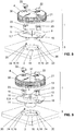
- eine Explosionsansicht der Ablaufanordnung nach
Figur 1 und2 mit dem Staufunktionsteil; - Fig. 5
- eine Explosionsansicht der Ablaufanordnung nach
Figur 1 und2 mit dem Notüberlauffunktionsteil; - Fig. 6
- eine Explosionsansicht der Ablaufanordnung mit dem Staufunktionsteil nach einer weiteren Variante;
- Fig. 7
- eine Explosionsansicht der Ablaufanordnung mit dem Notüberlauffunktionsteil nach der in
Figur 6 - Fig. 8
- eine Explosionsansicht der Ablaufanordnung mit dem Staufunktionsteil nach einer weiteren Variante; und
- Fig. 9
- eine Explosionsansicht der Ablaufanordnung mit dem Notüberlauffunktionsteil nach der in
Figur 8 gezeigten Variante.
- Fig. 1
- a perspective view of a drain assembly comprising a drainage drainage device and an inlet device;
- Fig. 2
- a sectional view of the drain assembly according to
FIG. 1 with a storage functional part; - Fig. 3
- a sectional view of the drain assembly according to
FIG. 1 with an emergency overflow function part; - Fig. 4
- an exploded view of the drain assembly after
FIG. 1 and2 with the storage functional part; - Fig. 5
- an exploded view of the drain assembly after
FIG. 1 and2 with the emergency overflow function part; - Fig. 6
- an exploded view of the drain assembly with the storage functional part according to another variant;
- Fig. 7
- an exploded view of the drain assembly with the emergency overflow function part after the in
FIG. 6 shown variant; - Fig. 8
- an exploded view of the drain assembly with the storage function part according to another variant; and
- Fig. 9
- an exploded view of the drain assembly with the emergency overflow function part after the in
FIG. 8 shown variant.
In der
Die
Die Einlaufvorrichtung 1 umfasst ein Abdeckteil 4 zur Abdeckung des Rohreintritts 2 und ein Funktionsteil 5. Das Funktionsteil 5 ist unterhalb des Abdeckteils 4 angeordnet. Das Abdeckteil 4 ist mit einer Vielzahl von seitlichen Durchgängen 21 versehen, durch welche Wasser zur Ablaufvorrichtung 3 zuführbar ist. Das Abdeckteil 4 und das Funktionsteil 5 sind zu einem gebäudeseitig montierten Halteelement 6 der Ablaufvorrichtung 3 befestigbar. Das Funktionsteil 5 ist wahlweise ein Staufunktionsteil 7 oder ein Notüberlauffunktionsteil 8. Mit anderen Worten gesagt: Das Funktionsteil 5 kann aus der Gruppe von Staufunktionsteil 7 und Notüberlauffunktionsteil 8 ausgewählt werden.The
Typischerweise werden auf einem zu entwässernden Gebäude mindestens eine bzw. eine Mehrzahl von Ablaufanordnung(en) 29 mit dem Staufunktionsteil 7 und mindestens eine bzw. eine Mehrzahl von Ablaufanordnung(en) 29 mit dem Notüberlauffunktionsteil 8 angeordnet.Typically, at least one building will be drained on a building to be drained A plurality of drain arrangement (s) 29 are arranged with the storage functional part 7 and at least one or a plurality of drainage arrangement (s) 29 with the emergency overflow function part 8.
In der
In der
Die Stauhöhe S des Staufunktionsteils 7 ist, wie in den
Das Abdeckteil 4 umfasst in der gezeigten Ausführung einen Deckelabschnitt 39, von welchem sich seitlich eine Vielzahl von Stegen 38 weg erstrecken. Die Stege 38 sind beabstandet zueinander angeordnet. Durch den Abstand werden die Durchgänge 21 geschaffen.The
Das Staufunktionsteil 7 und das Notüberlauffunktionsteil 8 verfügen über jeweils mindestens eine Befestigungsschnittstelle 15, über welche das jeweilige Funktionsteil 7, 8 zum Halteelement 6 der Ablaufvorrichtung 3 befestigbar ist. Die Befestigungsschnittstelle des Staufunktionsteils 7 ist dabei im Wesentlichen identisch zur Befestigungsschnittstelle des Notüberlauffunktionsteils 8 ausgebildet. Somit können beide Funktionsteile 7, 8 mit den gleichen Halteelementen 6 verbunden werden. Der Installateur kann vor Ort entscheiden, ob ein Staufunktionsteil 7 oder ein Notüberlauffunktionsteil 8 angeordnet werden soll, ohne dass an den Halteelementen 6 oder den Funktionsteilen 7, 8 Anpassungen vorgenommen werden müssen.The storage function part 7 and the emergency overflow function part 8 each have at least one
Von den
In der gezeigten Ausführungsform ist die besagte Befestigungsschnittstelle 15 Teil des Basisabschnittes 9. Die Befestigungsschnittstelle 15 wird hier als Öffnungen dargestellt, welches sich durch den Basisabschnitt 9 hindurch erstrecken. Über diese Öffnungen wird das Staufunktionsteil 7 bzw. das Notüberlauffunktionsteil 8 am Halteelement 6 gelagert. Das Halteelement 6 erstreckt sich dabei durch die Öffnung 15 hindurch.In the illustrated embodiment, said
Die Stauhöhe S wird durch die Oberseite 11 des scheibenförmigen Basisabschnittes 9 definiert. Das Wasser kann also bis zum Oberseite 11 des scheibenförmigen Basisabschnittes 9 ansteigen und erst dann wird das Ansaugen von Luft verhindert.The damming height S is defined by the top 11 of the disc-shaped
Beim Notüberlauffunktionsteil 8 weist der Basisabschnitt 9 eine den Einlauf 26 bereitstellende Durchlassöffnung 10 auf. Die Durchlassöffnung 10 wird hier durch eine Erhebung 12, die sich vom scheibenförmigen Basisabschnitt 9, erstreckt vollständig umgeben. Die Erhebung 12 umgibt die Durchlassöffnung 10 im Wesentlichen vollständig. Die Oberkante 13 der Erhebung 12 definiert dabei die Einlaufhöhe E. Die Erhebung 12 ist hier Teil eines Rohrabschnittes 14, welcher sich von der Oberkante 13 der Erhebung durch den scheibenförmigen Basisabschnitt 9 hindurch erstreckt und in Einbaulage, so wie in der
In den Explosionsansichten der
In den
In den
In den
Weiter ist in den gezeigten Ausführungsformen nach den
Im vorliegenden Fall sind zwei Befestigungselemente 17 angeordnet. Es wäre auch denkbar nur ein oder mehr als zwei Befestigungselemente 17 vorzusehen. Die Zahl der Halteelement 9 entspricht vorzugsweise der Zahl der Befestigungselemente.In the present case two
In der gezeigten Ausführungsform sind die Befestigungselemente 17 zweiteilig ausgebildet. Die Befestigungselement 17 umfassen dabei einen Aktuatorteil 22 und einen Verriegelungsteil 23. Das Aktuatorteil 22 steht dabei mit dem Verriegelungsteil 23 in Verbindung. Das Aktuatorteil 22 erstreckt sich dabei oberseitig zum Abdeckteil 4 sowie durch das Abdeckteil 4 hindurch und ist im Abdeckteil 4 drehbar gelagert. Das Aktuatorteil 22 kann von einem Installateur gut ergriffen werden. Das Verriegelungsteil 23 liegt unterseitig zum Abdeckteil 4 und arbeitet mit dem Halteelement 6 zusammen. Aktuatorteil 22 und Verriegelungsteil 23 werden vorzugsweise über eine Einrastverbindung miteinander verbunden. Das Befestigungselement 17 kann aber auch einteilig ausgebildet sein.In the embodiment shown, the
Oberhalb des Abdeckteils 4 weist hier das Befestigungselement 17 eine Grifflasche 30 auf. Die Grifflasche 30 kann vom Installateur zur Betätigung des Befestigungselementes ergriffen werden. Weiter erstreckt sich von der Oberseite des Abdeckteils 4 ein Kamm 31. Der Kamm 31 liegt hier zwischen zwei Befestigungselementen 17. Der Kamm 31 und die Grifflaschen 30 dienen dem Installateur der Signalisation der Stellung der Befestigungselemente. Liegen die Grifflaschen 30 fluchtend mit dem Kamm so befinden sich die Befestigungselemente 17 in der verriegelten Stellung. Liegt die Grifflasche 30 winklig zum Kamm 31 so liegt das Befestigungselement 17 in der entriegelten Stellung.Above the
Unterseitig weist das Befestigungselement 17 hier noch einen Noppen 32 auf. Der Noppen 32 ragt dabei in eine Ausnehmung 33 in Basisabschnitt 9 ein. Durch die Paarung Noppen 32 und Ausnehmung 33 kann eine Führung zwischen dem Befestigungselement 17 und dem Staufunktionsteil 7 bzw. dem Notüberlauffunktionsteil 8 bereitgestellt werden. Die Führung hilft bei der Betätigung des Befestigungselementes aber auch bei der Positionierung des Abdeckteils 4.On the underside, the
Weiter ist es vorteilhaft, wenn das Funktionsteil 7, 8 und das Abdeckteil 4 über Ausrichtelemente 27, 28 verfügen, wobei über die Ausrichtelemente 27, 28 das Abdeckteil 4 zum Funktionsteil 7, 8 ausrichtbar ist. In den gezeigten Ausführungsformen ist ein Ausrichtelement 27, 28 aus einer Paarung Erhebung und Ausnehmung bereitgestellt. Die Erhebung 27 wird durch die Stege 38 bereitgestellt, welche die Durchgänge 21 begrenzen und die Ausnehmung 28 erstreckt sich vom Rand in den Basisabschnitt 9 hinein.Furthermore, it is advantageous if the functional part 7, 8 and the
Wie in den
Vorzugsweise weist das Staufunktionsteils 7 eine strömungsoptimierte Form auf. Hierzu ist auf der Unterseite, die zur Ablaufvorrichtung 3 zugewandt ist, das Staufunktionsteil 7 entsprechend ausgebildet. Die strömungsoptimierten Elemente tragen das Bezugszeichen 34.
Claims (15)
wobei die Ablaufvorrichtung (3) einen Rohrstutzen (18) und mindestens ein Halteelement (6), das vorzugsweise mit dem Rohrstutzen (18) in Verbindung steht, aufweist, und
wobei die Einlaufvorrichtung ein Abdeckteil (4) zur Abdeckung des Rohreintritts (2) mit seitlichen Durchgängen (21), durch welche Wasser zum Rohreintritt (2) zuführbar ist, und ein Funktionsteil (5), welches unterhalb des Abdeckteils (4) angeordnet ist, umfasst
wobei das Funktionsteil (5) wahlweise ein eine Stauhöhe (S) definierendes Staufunktionsteil (7) oder ein Notüberlauffunktionsteil (8) mit einem eine Einlaufhöhe (E) definierenden Einlauf (26) ist, dadurch gekennzeichnet, dass
sowohl das Staufunktionsteil (7) als auch das Notüberlauffunktionsteil (8) und das Abdeckteil (4) zum besagten mindestens einen Halteelement (6) befestigbar sind.Drainage system (29) for roof drainage comprising a drainage device (3) and an inlet device (1),
wherein the discharge device (3) has a pipe socket (18) and at least one retaining element (6), which preferably communicates with the pipe socket (18), and
wherein the inlet device is a cover part (4) for covering the tube inlet (2) with lateral passages (21), through which water to the tube inlet (2) can be supplied, and a functional part (5), which is arranged below the cover member (4), includes
wherein the functional part (5) is optionally a storage function part (7) defining a storage height (S) or an emergency overflow function part (8) with an inlet (26) defining an inlet height (E), characterized in that
both the storage function part (7) and the emergency overflow function part (8) and the cover part (4) to said at least one holding element (6) can be fastened.
dass beim Staufunktionsteil (7) die Oberseite (11) des scheibenförmigen Basisabschnittes (9) die Stauhöhe (S) definiert und/oder
dass das Notüberlaufunktionsteil (8) der Basisabschnitt (9) eine den Einlauf (26) bereitstellende Durchlassöffnung (10) und eine sich vom scheibenförmigen Basisabschnitt (9) um die Durchlassöffnung (10) vollständig herum erstreckende Erhebung (12) umfasst, deren Oberkante (13) die Einlaufhöhe definiert.Drain arrangement (29) according to one of the preceding claims, characterized in that
in the case of the storage function part (7), the upper side (11) of the disk-shaped base section (9) defines the storage height (S) and / or
in that the emergency overflow function part (8) of the base section (9) comprises a passage opening (10) providing the inlet (26) and a projection (12) extending completely around the passage opening (10) from the disk-shaped base section (9), whose upper edge (13 ) defines the inlet height.
dass das Staufunktionsteil (7) beabstandet zum Rohrstutzen (18) angeordnet ist, so dass zwischen Rohreintritt (2) und der Stauscheibe ein freier Zwischenraum (35) geschaffen wird, durch welchen Wasser zum Rohrstutzen (18) fliessen kann, und/oder
dass das Notüberlauffunktionsteil (8) derart zum Rohrstutzen (18) angeordnet ist, dass Wasser ausschliesslich über den Einlauf (26) des Notüberlaufunktionsteil (8) in den Rohrstutzen einfliessen kann.Drain assembly (29) according to any one of the preceding claims 13 or 14, characterized in that between the underside of the cover member (4) and the Survey (26) a free space (37) is present, through which the water to be discharged to the inlet (26) can be fed, and / or
that the storage function part (7) is arranged at a distance from the pipe socket (18) so that a free intermediate space (35) is created between the pipe inlet (2) and the baffle plate, through which water can flow to the pipe socket (18), and / or
the emergency overflow function part (8) is arranged in such a way to the pipe stub (18) that water can flow into the pipe stub exclusively via the inlet (26) of the emergency overflow function part (8).
Priority Applications (3)
| Application Number | Priority Date | Filing Date | Title |
|---|---|---|---|
| PL19157327T PL3505703T3 (en) | 2015-06-12 | 2015-06-12 | Drain assembly |
| DK19157327.8T DK3505703T3 (en) | 2015-06-12 | 2015-06-12 | Drain device |
| EP19157327.8A EP3505703B1 (en) | 2015-06-12 | 2015-06-12 | Drain assembly |
Applications Claiming Priority (2)
| Application Number | Priority Date | Filing Date | Title |
|---|---|---|---|
| EP15171865.7A EP3103937B1 (en) | 2015-06-12 | 2015-06-12 | Drain assembly |
| EP19157327.8A EP3505703B1 (en) | 2015-06-12 | 2015-06-12 | Drain assembly |
Related Parent Applications (2)
| Application Number | Title | Priority Date | Filing Date |
|---|---|---|---|
| EP15171865.7A Division-Into EP3103937B1 (en) | 2015-06-12 | 2015-06-12 | Drain assembly |
| EP15171865.7A Division EP3103937B1 (en) | 2015-06-12 | 2015-06-12 | Drain assembly |
Publications (2)
| Publication Number | Publication Date |
|---|---|
| EP3505703A1 true EP3505703A1 (en) | 2019-07-03 |
| EP3505703B1 EP3505703B1 (en) | 2022-01-26 |
Family
ID=53397912
Family Applications (2)
| Application Number | Title | Priority Date | Filing Date |
|---|---|---|---|
| EP15171865.7A Active EP3103937B1 (en) | 2015-06-12 | 2015-06-12 | Drain assembly |
| EP19157327.8A Active EP3505703B1 (en) | 2015-06-12 | 2015-06-12 | Drain assembly |
Family Applications Before (1)
| Application Number | Title | Priority Date | Filing Date |
|---|---|---|---|
| EP15171865.7A Active EP3103937B1 (en) | 2015-06-12 | 2015-06-12 | Drain assembly |
Country Status (6)
| Country | Link |
|---|---|
| EP (2) | EP3103937B1 (en) |
| CN (1) | CN107646059A (en) |
| AU (1) | AU2016274373B2 (en) |
| DK (2) | DK3103937T3 (en) |
| PL (2) | PL3103937T3 (en) |
| WO (1) | WO2016198234A1 (en) |
Families Citing this family (1)
| Publication number | Priority date | Publication date | Assignee | Title |
|---|---|---|---|---|
| US10907356B2 (en) * | 2018-06-19 | 2021-02-02 | RPH Intellectual Holdings, LLC | Roof drain |
Citations (6)
| Publication number | Priority date | Publication date | Assignee | Title |
|---|---|---|---|---|
| US1762838A (en) * | 1929-01-23 | 1930-06-10 | Shand & Jurs Company | Roof drain |
| US2121220A (en) * | 1936-12-18 | 1938-06-21 | Paul Dickinson Inc | Roof drain |
| EP1013843A1 (en) * | 1998-12-24 | 2000-06-28 | Wolfgang Dipl.-Ing. Vahlbrauk | Free-head water drainage |
| WO2010103370A1 (en) * | 2009-03-10 | 2010-09-16 | Valsir S.P.A. | Water drain assembly, in particular for siphonic roof drainage systems |
| EP2468979A1 (en) * | 2010-11-26 | 2012-06-27 | VALSIR S.p.A. | Overflow device for water drain assemblies for drainage systems for roofs |
| EP2703576A1 (en) * | 2012-09-03 | 2014-03-05 | Geberit International AG | Covering device for covering the pipe entry of a drain element of a drainage system |
-
2015
- 2015-06-12 EP EP15171865.7A patent/EP3103937B1/en active Active
- 2015-06-12 DK DK15171865.7T patent/DK3103937T3/en active
- 2015-06-12 DK DK19157327.8T patent/DK3505703T3/en active
- 2015-06-12 EP EP19157327.8A patent/EP3505703B1/en active Active
- 2015-06-12 PL PL15171865T patent/PL3103937T3/en unknown
- 2015-06-12 PL PL19157327T patent/PL3505703T3/en unknown
-
2016
- 2016-05-13 AU AU2016274373A patent/AU2016274373B2/en active Active
- 2016-05-13 WO PCT/EP2016/060877 patent/WO2016198234A1/en active Application Filing
- 2016-05-13 CN CN201680029898.2A patent/CN107646059A/en active Pending
Patent Citations (6)
| Publication number | Priority date | Publication date | Assignee | Title |
|---|---|---|---|---|
| US1762838A (en) * | 1929-01-23 | 1930-06-10 | Shand & Jurs Company | Roof drain |
| US2121220A (en) * | 1936-12-18 | 1938-06-21 | Paul Dickinson Inc | Roof drain |
| EP1013843A1 (en) * | 1998-12-24 | 2000-06-28 | Wolfgang Dipl.-Ing. Vahlbrauk | Free-head water drainage |
| WO2010103370A1 (en) * | 2009-03-10 | 2010-09-16 | Valsir S.P.A. | Water drain assembly, in particular for siphonic roof drainage systems |
| EP2468979A1 (en) * | 2010-11-26 | 2012-06-27 | VALSIR S.p.A. | Overflow device for water drain assemblies for drainage systems for roofs |
| EP2703576A1 (en) * | 2012-09-03 | 2014-03-05 | Geberit International AG | Covering device for covering the pipe entry of a drain element of a drainage system |
Also Published As
| Publication number | Publication date |
|---|---|
| DK3103937T3 (en) | 2020-03-30 |
| DK3505703T3 (en) | 2022-04-19 |
| CN107646059A (en) | 2018-01-30 |
| EP3103937B1 (en) | 2020-01-01 |
| WO2016198234A1 (en) | 2016-12-15 |
| EP3505703B1 (en) | 2022-01-26 |
| EP3103937A1 (en) | 2016-12-14 |
| AU2016274373B2 (en) | 2021-08-05 |
| PL3505703T3 (en) | 2022-04-25 |
| PL3103937T3 (en) | 2020-06-29 |
| AU2016274373A1 (en) | 2017-11-16 |
Similar Documents
| Publication | Publication Date | Title |
|---|---|---|
| EP3101184B1 (en) | Sanitary insert unit | |
| EP0442135B1 (en) | Device for bringing together a plurality of infusions and/or injections | |
| DE102012101832A1 (en) | Surgical sterilization container and surgical fluid extraction device | |
| EP2149643A2 (en) | Drainage fitting with a drain trap with noise block with a flexible container | |
| EP3705655A1 (en) | Floor drain for removing water from a walkable floor into a sewer pipe | |
| EP3495576A2 (en) | System consisting of an odour trap and a receiving body and an odour trap | |
| DE102013107840A1 (en) | off device | |
| WO2015135728A1 (en) | Drain fitting for a floor drainage gully, and floor drainage gully having such a drain fitting | |
| EP3103937B1 (en) | Drain assembly | |
| EP1826334B1 (en) | Emergency overflow | |
| WO2014037413A1 (en) | Drain assembly and method for arranging a drain assembly on a drain connection of a sink | |
| EP3272954B1 (en) | Drain assembly | |
| EP1544360A1 (en) | Drainage device | |
| DE202019001142U1 (en) | Floor drain for removing water from a walk-in floor to a sewer | |
| EP2703576B1 (en) | Covering device for covering the pipe entry of a drain element of a drainage system | |
| EP3272955B1 (en) | Siphon assembly | |
| EP1013843B1 (en) | Free-head water drainage | |
| DE102017101109B4 (en) | Connecting piece for a drainage channel and gutter section | |
| EP3680406A1 (en) | Drainage device for being installed in the floor of a room | |
| DE102019125686A1 (en) | Drainage unit for draining surface water | |
| EP2808458B1 (en) | Water drainage device for a shower and shower floor element | |
| EP3567170A1 (en) | Drainage fitting for a shower or bath tub | |
| EP2641306B1 (en) | Exhaust chute for an overvoltage arrester, overvoltage arrester, and set of overvoltage arresters arranged in a row | |
| EP2735661A1 (en) | Sanitary basin | |
| DE20318617U1 (en) | inlet housing |
Legal Events
| Date | Code | Title | Description |
|---|---|---|---|
| PUAI | Public reference made under article 153(3) epc to a published international application that has entered the european phase |
Free format text: ORIGINAL CODE: 0009012 |
|
| STAA | Information on the status of an ep patent application or granted ep patent |
Free format text: STATUS: THE APPLICATION HAS BEEN PUBLISHED |
|
| AC | Divisional application: reference to earlier application |
Ref document number: 3103937 Country of ref document: EP Kind code of ref document: P |
|
| AK | Designated contracting states |
Kind code of ref document: A1 Designated state(s): AL AT BE BG CH CY CZ DE DK EE ES FI FR GB GR HR HU IE IS IT LI LT LU LV MC MK MT NL NO PL PT RO RS SE SI SK SM TR |
|
| STAA | Information on the status of an ep patent application or granted ep patent |
Free format text: STATUS: REQUEST FOR EXAMINATION WAS MADE |
|
| 17P | Request for examination filed |
Effective date: 20191108 |
|
| RBV | Designated contracting states (corrected) |
Designated state(s): AL AT BE BG CH CY CZ DE DK EE ES FI FR GB GR HR HU IE IS IT LI LT LU LV MC MK MT NL NO PL PT RO RS SE SI SK SM TR |
|
| STAA | Information on the status of an ep patent application or granted ep patent |
Free format text: STATUS: EXAMINATION IS IN PROGRESS |
|
| 17Q | First examination report despatched |
Effective date: 20200128 |
|
| STAA | Information on the status of an ep patent application or granted ep patent |
Free format text: STATUS: EXAMINATION IS IN PROGRESS |
|
| GRAP | Despatch of communication of intention to grant a patent |
Free format text: ORIGINAL CODE: EPIDOSNIGR1 |
|
| STAA | Information on the status of an ep patent application or granted ep patent |
Free format text: STATUS: GRANT OF PATENT IS INTENDED |
|
| RIN1 | Information on inventor provided before grant (corrected) |
Inventor name: HAUSHEER, ROMAN |
|
| INTG | Intention to grant announced |
Effective date: 20210709 |
|
| GRAJ | Information related to disapproval of communication of intention to grant by the applicant or resumption of examination proceedings by the epo deleted |
Free format text: ORIGINAL CODE: EPIDOSDIGR1 |
|
| STAA | Information on the status of an ep patent application or granted ep patent |
Free format text: STATUS: EXAMINATION IS IN PROGRESS |
|
| GRAP | Despatch of communication of intention to grant a patent |
Free format text: ORIGINAL CODE: EPIDOSNIGR1 |
|
| STAA | Information on the status of an ep patent application or granted ep patent |
Free format text: STATUS: GRANT OF PATENT IS INTENDED |
|
| GRAS | Grant fee paid |
Free format text: ORIGINAL CODE: EPIDOSNIGR3 |
|
| GRAA | (expected) grant |
Free format text: ORIGINAL CODE: 0009210 |
|
| STAA | Information on the status of an ep patent application or granted ep patent |
Free format text: STATUS: THE PATENT HAS BEEN GRANTED |
|
| INTG | Intention to grant announced |
Effective date: 20211203 |
|
| AC | Divisional application: reference to earlier application |
Ref document number: 3103937 Country of ref document: EP Kind code of ref document: P |
|
| AK | Designated contracting states |
Kind code of ref document: B1 Designated state(s): AL AT BE BG CH CY CZ DE DK EE ES FI FR GB GR HR HU IE IS IT LI LT LU LV MC MK MT NL NO PL PT RO RS SE SI SK SM TR |
|
| REG | Reference to a national code |
Ref country code: GB Ref legal event code: FG4D Free format text: NOT ENGLISH |
|
| REG | Reference to a national code |
Ref country code: CH Ref legal event code: EP |
|
| REG | Reference to a national code |
Ref country code: AT Ref legal event code: REF Ref document number: 1465409 Country of ref document: AT Kind code of ref document: T Effective date: 20220215 |
|
| REG | Reference to a national code |
Ref country code: IE Ref legal event code: FG4D Free format text: LANGUAGE OF EP DOCUMENT: GERMAN |
|
| REG | Reference to a national code |
Ref country code: DE Ref legal event code: R096 Ref document number: 502015015614 Country of ref document: DE |
|
| REG | Reference to a national code |
Ref country code: FI Ref legal event code: FGE |
|
| REG | Reference to a national code |
Ref country code: SE Ref legal event code: TRGR |
|
| REG | Reference to a national code |
Ref country code: NL Ref legal event code: FP |
|
| REG | Reference to a national code |
Ref country code: DK Ref legal event code: T3 Effective date: 20220411 |
|
| REG | Reference to a national code |
Ref country code: LT Ref legal event code: MG9D |
|
| PG25 | Lapsed in a contracting state [announced via postgrant information from national office to epo] |
Ref country code: RS Free format text: LAPSE BECAUSE OF FAILURE TO SUBMIT A TRANSLATION OF THE DESCRIPTION OR TO PAY THE FEE WITHIN THE PRESCRIBED TIME-LIMIT Effective date: 20220126 Ref country code: PT Free format text: LAPSE BECAUSE OF FAILURE TO SUBMIT A TRANSLATION OF THE DESCRIPTION OR TO PAY THE FEE WITHIN THE PRESCRIBED TIME-LIMIT Effective date: 20220526 Ref country code: NO Free format text: LAPSE BECAUSE OF FAILURE TO SUBMIT A TRANSLATION OF THE DESCRIPTION OR TO PAY THE FEE WITHIN THE PRESCRIBED TIME-LIMIT Effective date: 20220426 Ref country code: LT Free format text: LAPSE BECAUSE OF FAILURE TO SUBMIT A TRANSLATION OF THE DESCRIPTION OR TO PAY THE FEE WITHIN THE PRESCRIBED TIME-LIMIT Effective date: 20220126 Ref country code: HR Free format text: LAPSE BECAUSE OF FAILURE TO SUBMIT A TRANSLATION OF THE DESCRIPTION OR TO PAY THE FEE WITHIN THE PRESCRIBED TIME-LIMIT Effective date: 20220126 Ref country code: ES Free format text: LAPSE BECAUSE OF FAILURE TO SUBMIT A TRANSLATION OF THE DESCRIPTION OR TO PAY THE FEE WITHIN THE PRESCRIBED TIME-LIMIT Effective date: 20220126 Ref country code: BG Free format text: LAPSE BECAUSE OF FAILURE TO SUBMIT A TRANSLATION OF THE DESCRIPTION OR TO PAY THE FEE WITHIN THE PRESCRIBED TIME-LIMIT Effective date: 20220426 |
|
| PG25 | Lapsed in a contracting state [announced via postgrant information from national office to epo] |
Ref country code: LV Free format text: LAPSE BECAUSE OF FAILURE TO SUBMIT A TRANSLATION OF THE DESCRIPTION OR TO PAY THE FEE WITHIN THE PRESCRIBED TIME-LIMIT Effective date: 20220126 Ref country code: GR Free format text: LAPSE BECAUSE OF FAILURE TO SUBMIT A TRANSLATION OF THE DESCRIPTION OR TO PAY THE FEE WITHIN THE PRESCRIBED TIME-LIMIT Effective date: 20220427 |
|
| PG25 | Lapsed in a contracting state [announced via postgrant information from national office to epo] |
Ref country code: IS Free format text: LAPSE BECAUSE OF FAILURE TO SUBMIT A TRANSLATION OF THE DESCRIPTION OR TO PAY THE FEE WITHIN THE PRESCRIBED TIME-LIMIT Effective date: 20220526 |
|
| REG | Reference to a national code |
Ref country code: DE Ref legal event code: R097 Ref document number: 502015015614 Country of ref document: DE |
|
| PG25 | Lapsed in a contracting state [announced via postgrant information from national office to epo] |
Ref country code: SM Free format text: LAPSE BECAUSE OF FAILURE TO SUBMIT A TRANSLATION OF THE DESCRIPTION OR TO PAY THE FEE WITHIN THE PRESCRIBED TIME-LIMIT Effective date: 20220126 Ref country code: SK Free format text: LAPSE BECAUSE OF FAILURE TO SUBMIT A TRANSLATION OF THE DESCRIPTION OR TO PAY THE FEE WITHIN THE PRESCRIBED TIME-LIMIT Effective date: 20220126 Ref country code: RO Free format text: LAPSE BECAUSE OF FAILURE TO SUBMIT A TRANSLATION OF THE DESCRIPTION OR TO PAY THE FEE WITHIN THE PRESCRIBED TIME-LIMIT Effective date: 20220126 Ref country code: EE Free format text: LAPSE BECAUSE OF FAILURE TO SUBMIT A TRANSLATION OF THE DESCRIPTION OR TO PAY THE FEE WITHIN THE PRESCRIBED TIME-LIMIT Effective date: 20220126 Ref country code: CZ Free format text: LAPSE BECAUSE OF FAILURE TO SUBMIT A TRANSLATION OF THE DESCRIPTION OR TO PAY THE FEE WITHIN THE PRESCRIBED TIME-LIMIT Effective date: 20220126 |
|
| PG25 | Lapsed in a contracting state [announced via postgrant information from national office to epo] |
Ref country code: AL Free format text: LAPSE BECAUSE OF FAILURE TO SUBMIT A TRANSLATION OF THE DESCRIPTION OR TO PAY THE FEE WITHIN THE PRESCRIBED TIME-LIMIT Effective date: 20220126 |
|
| PLBE | No opposition filed within time limit |
Free format text: ORIGINAL CODE: 0009261 |
|
| STAA | Information on the status of an ep patent application or granted ep patent |
Free format text: STATUS: NO OPPOSITION FILED WITHIN TIME LIMIT |
|
| 26N | No opposition filed |
Effective date: 20221027 |
|
| PG25 | Lapsed in a contracting state [announced via postgrant information from national office to epo] |
Ref country code: MC Free format text: LAPSE BECAUSE OF FAILURE TO SUBMIT A TRANSLATION OF THE DESCRIPTION OR TO PAY THE FEE WITHIN THE PRESCRIBED TIME-LIMIT Effective date: 20220126 |
|
| REG | Reference to a national code |
Ref country code: BE Ref legal event code: MM Effective date: 20220630 |
|
| PG25 | Lapsed in a contracting state [announced via postgrant information from national office to epo] |
Ref country code: SI Free format text: LAPSE BECAUSE OF FAILURE TO SUBMIT A TRANSLATION OF THE DESCRIPTION OR TO PAY THE FEE WITHIN THE PRESCRIBED TIME-LIMIT Effective date: 20220126 |
|
| GBPC | Gb: european patent ceased through non-payment of renewal fee |
Effective date: 20220612 |
|
| PG25 | Lapsed in a contracting state [announced via postgrant information from national office to epo] |
Ref country code: LU Free format text: LAPSE BECAUSE OF NON-PAYMENT OF DUE FEES Effective date: 20220612 Ref country code: IE Free format text: LAPSE BECAUSE OF NON-PAYMENT OF DUE FEES Effective date: 20220612 Ref country code: FR Free format text: LAPSE BECAUSE OF NON-PAYMENT OF DUE FEES Effective date: 20220630 |
|
| PG25 | Lapsed in a contracting state [announced via postgrant information from national office to epo] |
Ref country code: GB Free format text: LAPSE BECAUSE OF NON-PAYMENT OF DUE FEES Effective date: 20220612 Ref country code: BE Free format text: LAPSE BECAUSE OF NON-PAYMENT OF DUE FEES Effective date: 20220630 |
|
| P01 | Opt-out of the competence of the unified patent court (upc) registered |
Effective date: 20230516 |
|
| PGFP | Annual fee paid to national office [announced via postgrant information from national office to epo] |
Ref country code: NL Payment date: 20230620 Year of fee payment: 9 Ref country code: DK Payment date: 20230622 Year of fee payment: 9 Ref country code: DE Payment date: 20230620 Year of fee payment: 9 |
|
| PGFP | Annual fee paid to national office [announced via postgrant information from national office to epo] |
Ref country code: SE Payment date: 20230620 Year of fee payment: 9 Ref country code: PL Payment date: 20230524 Year of fee payment: 9 Ref country code: FI Payment date: 20230621 Year of fee payment: 9 Ref country code: AT Payment date: 20230621 Year of fee payment: 9 |
|
| PGFP | Annual fee paid to national office [announced via postgrant information from national office to epo] |
Ref country code: IT Payment date: 20230621 Year of fee payment: 9 Ref country code: CH Payment date: 20230702 Year of fee payment: 9 |
|
| PG25 | Lapsed in a contracting state [announced via postgrant information from national office to epo] |
Ref country code: HU Free format text: LAPSE BECAUSE OF FAILURE TO SUBMIT A TRANSLATION OF THE DESCRIPTION OR TO PAY THE FEE WITHIN THE PRESCRIBED TIME-LIMIT; INVALID AB INITIO Effective date: 20150612 |
|
| PG25 | Lapsed in a contracting state [announced via postgrant information from national office to epo] |
Ref country code: MK Free format text: LAPSE BECAUSE OF FAILURE TO SUBMIT A TRANSLATION OF THE DESCRIPTION OR TO PAY THE FEE WITHIN THE PRESCRIBED TIME-LIMIT Effective date: 20220126 Ref country code: CY Free format text: LAPSE BECAUSE OF FAILURE TO SUBMIT A TRANSLATION OF THE DESCRIPTION OR TO PAY THE FEE WITHIN THE PRESCRIBED TIME-LIMIT Effective date: 20220126 |