EP3505703B1 - Drain assembly - Google Patents
Drain assembly Download PDFInfo
- Publication number
- EP3505703B1 EP3505703B1 EP19157327.8A EP19157327A EP3505703B1 EP 3505703 B1 EP3505703 B1 EP 3505703B1 EP 19157327 A EP19157327 A EP 19157327A EP 3505703 B1 EP3505703 B1 EP 3505703B1
- Authority
- EP
- European Patent Office
- Prior art keywords
- functional part
- build
- emergency overflow
- functional
- drain assembly
- Prior art date
- Legal status (The legal status is an assumption and is not a legal conclusion. Google has not performed a legal analysis and makes no representation as to the accuracy of the status listed.)
- Active
Links
- XLYOFNOQVPJJNP-UHFFFAOYSA-N water Substances O XLYOFNOQVPJJNP-UHFFFAOYSA-N 0.000 claims description 34
- 238000009434 installation Methods 0.000 claims 1
- 238000009825 accumulation Methods 0.000 description 30
- 238000000034 method Methods 0.000 description 2
- 241000792859 Enema Species 0.000 description 1
- 230000001419 dependent effect Effects 0.000 description 1
- 239000007920 enema Substances 0.000 description 1
- 229940095399 enema Drugs 0.000 description 1
- 238000012986 modification Methods 0.000 description 1
- 230000004048 modification Effects 0.000 description 1
Images


Classifications
-
- E—FIXED CONSTRUCTIONS
- E04—BUILDING
- E04D—ROOF COVERINGS; SKY-LIGHTS; GUTTERS; ROOF-WORKING TOOLS
- E04D13/00—Special arrangements or devices in connection with roof coverings; Protection against birds; Roof drainage; Sky-lights
- E04D13/04—Roof drainage; Drainage fittings in flat roofs, balconies or the like
- E04D13/0404—Drainage on the roof surface
- E04D13/0409—Drainage outlets, e.g. gullies
- E04D2013/0413—Strainers for drainage outlets
Definitions
- the present invention relates to a drain arrangement for roof drainage comprising a drain device and an inlet device according to the preamble of claim 1.
- Drainage systems for surfaces such as flat roofs are known from the prior art. Such drainage systems include a pipe system through which the water lying on the surfaces is discharged. Typically, there is a negative pressure in the pipe system, which ensures fast and safe drainage.
- EP 2468979 A1 also discloses a generic drain arrangement with a drain device and an inlet device.
- the object of the invention is to specify a drain arrangement for roof drainage systems which overcomes the disadvantages of the prior art.
- a drainage device is to be specified which can be mounted as flexibly as possible.
- a drain arrangement for roof drainage comprises a drain device and an inlet device.
- the drain device has a pipe socket and at least one Retaining element, which is preferably connected to the pipe socket, on.
- the holding element could also be fixed in some other way, for example on the building side.
- the inlet device comprises a cover part for covering the pipe inlet with lateral passages through which water can be fed to the pipe inlet, and two functional parts which can be optionally arranged below the cover part.
- One of the functional parts is a storage function part that defines a storage height
- another of the functional parts is an emergency overflow function part with an inlet that defines an inlet height. Both the storage function part and the emergency overflow function part and the cover part can be fastened to said at least one holding element.
- the holding element thus serves to accommodate the accumulation function part and the cover part or the emergency overflow function part and the cover part.
- the pairing of storage function part and cover part and the pairing of emergency overflow function part and cover part can be fastened to the same holding element. This design is advantageous because there is no need to adapt the holding elements with regard to the function of the drain arrangement.
- the installer can decide on site whether the parts of the drain arrangement can be used as an emergency overflow or as a normal inlet.
- Both the accumulation function part and the emergency overflow function part are preferably held by the cover part on the holding element.
- the cover part serves as a fastening means for the storage function part and the emergency overflow function part to the holding element. Additional fastening elements can therefore be omitted.
- Exactly two holding elements are particularly preferably arranged diametrically opposite one another with respect to the pipe socket.
- a functional part can function as a backup function part or as an emergency overflow function part to be provided.
- the accumulation function part is designed differently than the emergency overflow function part.
- the cover part is identical in both cases. Consequently, there is the advantage that the inlet device is versatile, i.e. with the two functions "normal process” and “emergency process” can be provided, with only the corresponding functional part having to be selected.
- the cover part particularly preferably provides an interior space in which the functional part is located.
- the interior is accessible through said breakthroughs.
- the storage function part has at least one attachment interface for attaching the storage function part to the holding element and the emergency overflow function part has at least one attachment interface for attaching the emergency overflow function part to the holding element.
- Said attachment interface of the accumulation function part and the attachment interface of the emergency overflow function part are designed essentially identical to one another.
- the accumulation function part and the emergency overflow function part preferably have a disc-shaped base section, with the disk-shaped base section of the accumulation function part and that of the emergency overflow function part preferably being at the same level in the assembled state.
- the base section can include and/or accommodate and/or provide at least parts of the fastening interface.
- the attachment interface of the accumulation function part and the attachment interface of the emergency overflow part have the shape of an opening.
- several openings can be arranged.
- the number of holding elements preferably corresponds to the number of openings.
- the opening or openings are arranged in the same position and/or in the same position on the accumulation function part and on the emergency overflow function part.
- the opening is preferably arranged in the disc-shaped base section.
- the disc-shaped base section can be designed differently in the area of the opening.
- the disc-shaped base section is flat in the area of the opening.
- the disc-shaped base section has a bulge in the area of the opening, which bulge extends away from the cover part, with the opening being arranged in the bulge.
- the shape of the base section is changed by the bulge, whereby the shape of the holding element, which is mounted on the building side, can also be changed. If the bulge protrudes in the direction of the building, for example, the holding element can be made shorter, which is advantageous during assembly with regard to unintentional deformation by the installer.
- the bulge in the storage function part is preferably designed identically to the bulge in the emergency overflow function part.
- At least one fastening element is displaceably mounted on the cover part, with which fastening element the cover part can be fastened to the holding element.
- the fastening element can preferably be rotated about an axis.
- the number of fastening elements preferably corresponds to the number of holding elements.
- the fastening elements are preferably arranged in the same position and/or in the same position as the openings.
- the fastening element can be designed in one piece or in several pieces.
- the fastening element comprises an actuator part and a locking part which are connected to one another, with the actuator part being at least partially on top of the cover part and the locking part being at least partially on the underside of the cover part.
- the holding element is preferably designed as a pin with a notch, in particular a circumferential groove, it being possible for the cover part to be fastened to the holding element, in particular with the fastening element, via the notch
- the holding element preferably has a bearing surface on which the functional part is supported, in particular with the underside of the base section.
- the storage area is preferably arranged at a distance from the notch, which distance preferably corresponds to the thickness of the base portion.
- the functional part and the cover part preferably have alignment elements, in particular recesses and elevations, it being possible for the cover part to be aligned with the functional part via the alignment elements.
- Recesses are preferably arranged on the functional part and the webs, which delimit the openings on the cover part, serve as elevations.
- the base section preferably comprises a through-opening providing the inlet and an elevation which extends completely around the through-opening from the disc-shaped base section and whose upper edge defines the inlet height.
- the base section of the accumulation function part and the base section of the emergency overflow function part are essentially at the same level.
- the elevation is particularly preferably part of a pipe section, which extends from the upper edge of the elevation through the disk-shaped base section and protrudes into the pipe inlet of the drain pipe in the installed position.
- the storage function part is preferably arranged at a distance from the pipe socket, so that water can flow into the pipe socket through the distance. An intermediate space is thus created between the accumulation function part, in particular its base section, and the pipe inlet, through which the water can flow. Until the level of the accumulation function part is reached, the water flows normally with air into the pipe socket. As soon as the accumulation height is exceeded, the accumulation function part prevents further inflow of air into the pipe socket, which promotes the drainage of water.
- the emergency overflow function part is preferably arranged relative to the pipe socket in such a way that water can only flow into the pipe socket via the inlet of the emergency overflow function part. In particular, the piece of pipe of the emergency overflow functional part protrudes into the pipe socket. A seal is preferably arranged between the piece of pipe and the pipe socket.
- the storage function part serves to prevent air from entering the drain pipe when the water level on the building has reached or exceeded a storage level.
- the emergency overflow function part has an inlet defining an inlet height, with the emergency overflow function part providing an emergency outlet when the water level on the building exceeds the inlet height.
- the accumulation height of the accumulation function part is lower than or equal to the inlet height of the emergency overflow function part.
- FIG 1 a perspective view of a drain assembly 29 is shown.
- the outflow arrangement 29 comprises an outflow device 3 for the building drainage and an inlet device 1 which is arranged above the outflow device 3 .
- the water to be discharged is fed to the discharge device 3 via the inlet device 1 .
- Such a drain arrangement 29 shown in the figures is typically arranged in the building drainage on a roof. However, other areas that cannot be part of a building can also be drained.
- the building is only shown symbolically in the figures and bears the reference symbol G.
- FIGS. 2 and 3 show a sectional view of the outlet device 29.
- the inlet device 1 is shown in more detail. Based on Figures 2 and 3 the inlet device 1 will now be explained in more detail.
- the inlet device 1 comprises a cover part 4 for covering the pipe inlet 2 and a functional part 5 .
- the functional part 5 is arranged below the cover part 4 .
- the cover part 4 is provided with a multiplicity of lateral passages 21 through which water can be supplied to the drainage device 3 .
- the cover part 4 and the functional part 5 can be fastened to a holding element 6 of the drain device 3 mounted on the building side.
- the functional part 5 is either a storage function part 7 or an emergency overflow function part 8. In other words, the functional part 5 can be selected from the group of storage function part 7 and emergency overflow function part 8.
- a plurality of drain arrangement(s) 29 with the accumulation function part 7 and at least one or a plurality of drain arrangement(s) 29 with the emergency overflow function part 8 are arranged.
- the functional part 5 is shown as a storage function part 7 .
- the accumulation function part 7 is at a distance from the pipe inlet 2 of the discharge device 3 so that there is a free space 35 between the pipe inlet 2 and the accumulation function part 7 .
- the water to be discharged flows to the pipe inlet 2 through this free intermediate space 35 .
- the water flow is represented by the arrow W.
- the storage function part 7 serves to prevent air from entering the drain pipe 3 when the water level on the building has reached or exceeded a storage height S.
- the water level S is in the figure 2 marked with a dashed line.
- the inflow, here the intermediate space 37, to the pipe inlet 2 is completely filled with water and air can be prevented from entering the pipe inlet 2. Due to the resulting flow conditions, the discharge capacity can be increased.
- the emergency overflow functional part 8 includes an inlet 26 which defines an inlet height E.
- the emergency overflow function part 8 provides an emergency drain when the water level on the building G exceeds the inlet height E.
- the inlet height E is shown with a dashed line. Between the underside of the cover part 4 and the elevation 13 there is a free intermediate space 37 through which the water to be discharged can be fed to the inlet 26 .
- the storage height S of the storage function part 7 is, as in the Figures 2 and 3 shown, lower than or equal to the inlet height E of the emergency overflow function part 8. This means that until the inlet height E is reached, the water flows out via those drainage arrangements which are equipped with the storage function part 7 and when the inlet height E is exceeded, the water flows out via those drainage arrangements which are equipped with the emergency overflow function part 8.
- the cover part 4 comprises a cover section 39 of which a plurality of webs 38 extend laterally away.
- the webs 38 are arranged at a distance from one another.
- the passages 21 are created by the spacing.
- the accumulation function part 7 and the emergency overflow function part 8 each have at least one attachment interface 15, via which the respective function part 7, 8 can be attached to the holding element 6 of the drain device 3.
- the attachment interface of the accumulation function part 7 is essentially identical in design to the attachment interface of the emergency overflow function part 8 .
- both functional parts 7, 8 can be connected to the same holding elements 6. The installer can decide on site whether a storage function part 7 or an emergency overflow function part 8 should be arranged without having to make any adjustments to the holding elements 6 or the function parts 7, 8.
- both the accumulation function part 7 and the emergency overflow function part 8 have a disk-shaped base section 9 .
- the disk-shaped base section 9 of the accumulation function part 7 and that of the emergency overflow function part 8 are preferably at the same height.
- said attachment interface 15 is part of the base portion 9.
- the attachment interface 15 is shown here as openings extending through the base portion 9.
- the accumulation function part 7 or the emergency overflow function part 8 is mounted on the holding element 6 via these openings.
- the holding element 6 extends through the opening 15 .
- the accumulation height S is defined by the upper side 11 of the disc-shaped base section 9 .
- the water can therefore rise to the top 11 of the disc-shaped base section 9 and only then is the suction of air prevented.
- the base section 9 has a passage opening 10 providing the inlet 26 .
- the through-opening 10 is completed here by an elevation 12 which extends from the disc-shaped base section 9 surround.
- the elevation 12 essentially completely surrounds the passage opening 10 .
- the top edge 13 of the survey 12 defines the inlet height E.
- the survey 12 is part of a pipe section 14 here, which extends from the top edge 13 of the survey through the disc-shaped base section 9 and in the installed position, as in FIG figure 3 shown, in the pipe inlet 2 of the drain device 3 protrudes.
- the connection between pipe section 14 and raw inlet 2 is preferably designed to be watertight. The water flows along the arrow W through the passages 21 of the cover part 4 and then flows via the elevation 12 into the pipe section 14 and thus into the drain device 3 .
- the opening 15 is arranged in the base section 9 .
- the disk-shaped base section 9 is planar, ie flat, in the area of the opening 15 .
- the disc-shaped base section 9 is formed with a bulge 16 in the area of the opening 15 .
- the bulge 16 extends away from the cover part 4, ie in the direction of the drain device 3.
- the opening 15 is located at the base of the bulge 16 and is therefore arranged in the bulge 16.
- the bulge 16 has the advantage that the underside of the disc-shaped base section 9, which faces the drain device 3, is closer to the drain device 3.
- the holding elements 6 can be designed to be correspondingly shorter, which has the advantage during assembly that they can be pushed off less by tools or installers. This function is when comparing the length of the support members 6 between the Figures 4 and 5 and the Figures 6 to 9 apparently.
- the bulge 9 is arranged in such a way that it is surrounded by the base portion 9 .
- the bulge 9 is arranged in such a way that it is open with respect to the edge of the base section 9 .
- a fastener 17 mounted on the cover 4 slidably.
- the fastening element 17 is rotatably mounted here on the cover part 4 and can be brought from an unlocked position into a locked position.
- the fastening element 17 works together with the holding element 6 and secures the cover part 4 and the functional part 7, 8 to the holding element 6. In the locked position, the cover part 4 and the functional parts 7, 8 cannot be separated from the holding element 6.
- the two parts can be removed from the holding element 6 in the unlocked position.
- the fastening element 17 engages with a locking recess 36 in a groove 20 on the holding element 6, which here is in the form of a pin 19.
- the groove 20 can also be a notch that does not run all the way round.
- the cover part 4 is secured to the holding element 6 .
- the holding element 6 also includes a bearing surface 24 .
- the holding element 6 also protrudes through the opening 15 on the functional element 7 , 8 and the latter rests with its underside 25 on the bearing surface 24 . Due to the contact with the fastening element 17, the functional element 7, 8 is clamped between the bearing surface 24 and the fastening element 17 and is thus secured to the holding element 6.
- two fastening elements 17 are arranged. It would also be conceivable to provide only one or more than two fastening elements 17 .
- the number of holding elements 9 preferably corresponds to the number of fastening elements.
- the fastening elements 17 are designed in two parts.
- the fastening element 17 comprises an actuator part 22 and a locking part 23.
- the actuator part 22 is connected to the locking part 23.
- the actuator part 22 extends on the upper side to the cover part 4 and through the cover part 4 and is rotatably mounted in the cover part 4 .
- the actuator part 22 can be easily gripped by an installer.
- the locking part 23 is on the underside of the cover part 4 and works together with the holding element 6 .
- Actuator part 22 and locking part 23 are preferably connected to one another via a snap-in connection.
- the fastening element 17 can also be designed in one piece.
- the fastening element 17 has a grip tab 30 above the cover part 4 .
- the grip tab 30 can be grasped by the installer to operate the fastener.
- a comb 31 extends further from the upper side of the cover part 4.
- the comb 31 lies here between two fastening elements 17.
- the comb 31 and the gripping tabs 30 serve to signal the position of the fastening elements to the installer. If the grip tabs 30 are aligned with the comb, the fastening elements 17 are in the locked position. If the grip tab 30 is at an angle to the comb 31, the fastening element 17 is in the unlocked position.
- the fastening element 17 also has a nub 32 on the underside here.
- the nub 32 protrudes into a recess 33 in the base section 9 .
- the pairing of nubs 32 and recess 33 can provide guidance between the fastening element 17 and the accumulation function part 7 or the emergency overflow function part 8 .
- the guide helps when actuating the fastening element but also when positioning the cover part 4.
- an alignment element 27, 28 is provided from a pairing of elevation and recess.
- the elevation 27 is provided by the ridges 38 delimiting the passages 21 and the recess 28 extends into the base portion 9 from the edge.
- the drain device 3 comprises a pipe socket 18 and at least one holding element 6 connected to the pipe socket 18. In the embodiment shown, two holding elements 6 are shown in each case.
- the cover part 4 and the storage function part 7 or the emergency overflow function part 8 are fastened to the holding element 6 with the fastening element 17 .
- the storage function part 7 is arranged at a distance from the pipe socket 18 so that water can flow into the pipe socket 18 through this distance.
- the emergency overflow function part 8 is arranged relative to the pipe socket 18 in such a way that water can flow into the pipe socket 18 exclusively via the inlet 26 of the emergency overflow function part 8 .
- the accumulation function part 7 preferably has a flow-optimized shape.
- the accumulation function part 7 is designed accordingly on the underside, which faces the drainage device 3 .
- the flow-optimized elements bear the reference number 34.
Description
Die vorliegende Erfindung betrifft eine Ablaufanordnung für die Dachentwässerung umfassend eine Ablaufvorrichtung und eine Einlaufvorrichtung nach dem Oberbegriff von Anspruch 1.The present invention relates to a drain arrangement for roof drainage comprising a drain device and an inlet device according to the preamble of
Aus dem Stand der Technik sind Entwässerungssysteme für Flächen, wie beispielsweise Flachdächer, bekannt. Solche Entwässerungssysteme umfassen dabei ein Rohrsystem, über welches das auf den Flächen liegende Wasser abgeführt wird. Typischerweise herrscht im Rohrsystem ein Unterdruck, welcher für eine schnelle und sichere Entwässerung sorgt.Drainage systems for surfaces such as flat roofs are known from the prior art. Such drainage systems include a pipe system through which the water lying on the surfaces is discharged. Typically, there is a negative pressure in the pipe system, which ensures fast and safe drainage.
Die Anmelderin selbst vertreibt ein solches Entwässerungssystem unter dem Namen Pluvia.
Ausgehend von diesem Stand der Technik liegt der Erfindung eine Aufgabe zugrunde, eine Ablaufanordnung für Dachentwässerungssysteme anzugeben, welche die Nachteile des Standes der Technik überwindet. Insbesondere soll eine Ablaufvorrichtung angegeben werden, welche möglichst flexibel montierbar ist.Proceeding from this prior art, the object of the invention is to specify a drain arrangement for roof drainage systems which overcomes the disadvantages of the prior art. In particular, a drainage device is to be specified which can be mounted as flexibly as possible.
Diese Aufgabe löst der Gegenstand von Anspruch 1. Demgemäss umfasst eine Ablaufanordnung für die Dachentwässerung eine Ablaufvorrichtung und eine Einlaufvorrichtung. Die Ablaufvorrichtung weist einen Rohrstutzen und mindestens ein Halteelement, das vorzugsweise mit dem Rohrstutzen in Verbindung steht, auf. Das Halteelement könnte auch anderweitig befestigt sein, beispielsweise gebäudeseitig. Die Einlaufvorrichtung umfasst ein Abdeckteil zur Abdeckung des Rohreintritts mit seitlichen Durchgängen, durch welche Wasser zum Rohreintritt zuführbar ist, und zwei Funktionsteile, welche unterhalb des Abdeckteils wahlweise anordbar sind. Eines der Funktionsteile ist ein eine Stauhöhe definierendes Staufunktionsteil und ein anderes der Funktionsteile ist ein Notüberlauffunktionsteil mit einem eine Einlaufhöhe definierenden Einlauf. Sowohl das Staufunktionsteil als auch das Notüberlauffunktionsteil und das Abdeckteil sind zum besagten mindestens einen Halteelement befestigbar.This object is achieved by the subject matter of
Das Halteelement dient also der Aufnahme des Staufunktionsteils und des Abdeckteils bzw. des Notüberlauffunktionsteils und des Abdeckteils. Somit kann die also die Paarung Staufunktionsteils und Abdeckteil und die Paarung Notüberlauffunktionsteil und Abdeckteil am gleichen Halteelement befestigt werden. Diese Ausbildung ist vorteilhaft, weil eine Anpassung der Halteelemente mit Blick auf die Funktion der Ablaufanordnung entfällt.The holding element thus serves to accommodate the accumulation function part and the cover part or the emergency overflow function part and the cover part. Thus, the pairing of storage function part and cover part and the pairing of emergency overflow function part and cover part can be fastened to the same holding element. This design is advantageous because there is no need to adapt the holding elements with regard to the function of the drain arrangement.
Darüber hinaus ergeht auch der Vorteil, dass die Ablaufanordnung flexibler einsetzbar ist.In addition, there is also the advantage that the drain arrangement can be used more flexibly.
So kann der Installateur vor Ort entscheiden, ob die Teile der Ablaufanordnung als Notüberlauf oder als normaler Einlauf eingesetzt werden können.In this way, the installer can decide on site whether the parts of the drain arrangement can be used as an emergency overflow or as a normal inlet.
Vorzugsweise werden sowohl das Staufunktionsteil als auch das Notüberlauffunktionsteil durch das Abdeckteil am Halteelement gehalten. In diesem Fall dient das Abdeckteil als Befestigungsmittel für das Staufunktionsteil und das Notüberlauffunktionsteil zum Halteelement. Es können also zusätzliche Befestigungselemente entfallen.Both the accumulation function part and the emergency overflow function part are preferably held by the cover part on the holding element. In this case, the cover part serves as a fastening means for the storage function part and the emergency overflow function part to the holding element. Additional fastening elements can therefore be omitted.
Besonders bevorzugt sind genau zwei Halteelement bezüglich des Rohrstutzens diametral gegenüber einander angeordnet.Exactly two holding elements are particularly preferably arranged diametrically opposite one another with respect to the pipe socket.
Ein Funktionsteil kann wie erwähnt als Staufunktionsteil oder als Notüberlauffunktionsteil bereitgestellt werden. Das Staufunktionsteil ist dabei unterschiedlich ausgebildet als das Notüberlauffunktionsteil. Identisch ist aber das Abdeckteil in beiden Fällen. Folglich ergeht der Vorteil, dass die Einlaufvorrichtung vielseitig, also mit den beiden Funktionen "normaler Ablauf" und "Notablauf" bereitgestellt werden kann, wobei lediglich das entsprechende Funktionsteil gewählt werden muss.As mentioned, a functional part can function as a backup function part or as an emergency overflow function part to be provided. The accumulation function part is designed differently than the emergency overflow function part. However, the cover part is identical in both cases. Consequently, there is the advantage that the inlet device is versatile, i.e. with the two functions "normal process" and "emergency process" can be provided, with only the corresponding functional part having to be selected.
Besonders bevorzugt stellt das Abdeckteil einen Innenraum bereit, in welchem das Funktionsteil liegt. Der Innenraum ist durch besagten Durchbrüche zugänglich.The cover part particularly preferably provides an interior space in which the functional part is located. The interior is accessible through said breakthroughs.
Erfindungsgemäß verfügt das Staufunktionsteil über mindestens eine Befestigungsschnittstelle zur Befestigung des Staufunktionsteils zum Halteelement und das Notüberlauffunktionsteil verfügt über mindestens eine Befestigungsschnittstelle zur Befestigung des Notüberlauffunktionsteils zum Haltelement. Die besagte Befestigungsschnittstelle des Staufunktionsteils und die Befestigungsschnittstelle des Notüberlauffunktionsteils sind dabei im Wesentlichen identisch zueinander ausgebildet.According to the invention, the storage function part has at least one attachment interface for attaching the storage function part to the holding element and the emergency overflow function part has at least one attachment interface for attaching the emergency overflow function part to the holding element. Said attachment interface of the accumulation function part and the attachment interface of the emergency overflow function part are designed essentially identical to one another.
Unter einer identischen Ausbildung der Befestigungsschnittstelle wird verstanden, dass bei der Anordnung der Halteelemente keine Modifikationen bei wechselnder Befestigung des Staufunktionsteils oder des Notüberlauffunktionsteil nötig ist. Das heisst, bei einer gegebenen Konfiguration der Halteelemente kann sowohl das Staufunktionsteil als auch das Notüberlauffunktionsteil mit den Halteelementen verbunden werden.An identical design of the fastening interface is understood to mean that no modifications are necessary when the retaining elements are arranged when the accumulation function part or the emergency overflow function part is fastened alternately. This means that with a given configuration of the holding elements, both the storage function part and the emergency overflow function part can be connected to the holding elements.
Vorzugsweise weist das Staufunktionsteil und das Notüberlauffunktionsteil einen scheibenförmigen Basisabschnitt auf, wobei im montierten Zustand der scheibenförmige Basisabschnitt des Staufunktionsteil und derjenige des Notüberlauffunktionsteil vorzugsweise auf gleicher Höhe liegen.The accumulation function part and the emergency overflow function part preferably have a disc-shaped base section, with the disk-shaped base section of the accumulation function part and that of the emergency overflow function part preferably being at the same level in the assembled state.
Der Basisabschnitt kann dabei mindestens Teile der Befestigungsschnittstelle umfassen und/oder aufnehmen und/oder bereitstellen.The base section can include and/or accommodate and/or provide at least parts of the fastening interface.
Vorzugsweise weist die Befestigungsschnittstelle des Staufunktionsteils und die Befestigungsschnittstelle des Notüberlaufteils die Gestalt von einer Öffnung auf. Je nach Zahl der Halteelemente können mehrere Öffnungen angeordnet sein. Die Zahl der Halteelemente entspricht vorzugsweise der Zahl der Öffnungen. Die Öffnung bzw. die Öffnungen sind am Staufunktionsteil und am Notüberlauffunktionsteil lagegleich und/oder positionsgleich angeordnet.Preferably, the attachment interface of the accumulation function part and the attachment interface of the emergency overflow part have the shape of an opening. Depending on the number of holding elements, several openings can be arranged. The number of holding elements preferably corresponds to the number of openings. The opening or openings are arranged in the same position and/or in the same position on the accumulation function part and on the emergency overflow function part.
Vorzugsweise ist die Öffnung im scheibenförmigen Basisabschnitt angeordnet. Der scheibenförmige Basisabschnitt kann im Bereich der Öffnung unterschiedlich ausgebildet sein. In einer ersten Ausbildung ist der scheibenförmige Basisabschnitt im Bereich der Öffnung eben ausgebildet. In einer zweiten Ausbildung weist der scheibenförmige Basisabschnitt im Bereich der Öffnung eine Ausbuchtung auf, die sich vom Abdeckteil weg erstreckt, wobei die Öffnung in der Ausbuchtung angeordnet ist. Durch die Ausbuchtung wird die Form des Basisabschnittes verändert, wodurch auch die Form des Haltelementes, das gebäudeseitig montiert wird, verändert werden kann. Ragt die Ausbuchtung beispielsweise Richtung Gebäude, so kann das Halteelement kürzer ausgebildet werden, was bei der Montage bezüglich einer unbeabsichtigten Verformung durch den Installateur vorteilhaft ist. Die Ausbuchtung im Staufunktionsteil ist dabei vorzugsweise identisch zur Ausbuchtung im Notüberlauffunktionsteil ausgebildet.The opening is preferably arranged in the disc-shaped base section. The disc-shaped base section can be designed differently in the area of the opening. In a first embodiment, the disc-shaped base section is flat in the area of the opening. In a second embodiment, the disc-shaped base section has a bulge in the area of the opening, which bulge extends away from the cover part, with the opening being arranged in the bulge. The shape of the base section is changed by the bulge, whereby the shape of the holding element, which is mounted on the building side, can also be changed. If the bulge protrudes in the direction of the building, for example, the holding element can be made shorter, which is advantageous during assembly with regard to unintentional deformation by the installer. The bulge in the storage function part is preferably designed identically to the bulge in the emergency overflow function part.
Vorzugsweise ist mindestens ein Befestigungselement am Abdeckteil verschiebbar gelagert, mit welchem Befestigungselement das Abdeckteil zum Halteelement befestigbar ist. Vorzugsweise ist das Befestigungselement um eine Achse verdrehbar. Die Zahl der Befestigungselemente entspricht bevorzugt der Zahl der Halteelemente. Die Befestigungselemente sind vorzugsweise lagegleich und/oder positionsgleich zu den Öffnungen angeordnet.Preferably, at least one fastening element is displaceably mounted on the cover part, with which fastening element the cover part can be fastened to the holding element. The fastening element can preferably be rotated about an axis. The number of fastening elements preferably corresponds to the number of holding elements. The fastening elements are preferably arranged in the same position and/or in the same position as the openings.
Das Befestigungselement kann einteilig oder mehrteilig ausgebildet sein. In der mehrteiligen Ausbildung umfasst das Befestigungselement ein Aktuatorteil und ein Verriegelungsteil, welche miteinander in Verbindung stehen, wobei das Aktuatorteil mindestens teilweise oberseitig zum Abdeckteil und das Verriegelungsteil mindestens teilweise unterseitig zum Abdeckteil liegt.The fastening element can be designed in one piece or in several pieces. In the multi-part design, the fastening element comprises an actuator part and a locking part which are connected to one another, with the actuator part being at least partially on top of the cover part and the locking part being at least partially on the underside of the cover part.
Vorzugsweise ist das Halteelement als Zapfen mit einer Kerbe, insbesondere einer umlaufenden Rille, ausgebildet, wobei das Abdeckteil, insbesondere mit dem Befestigungselement, über die Kerbe zum Haltelement befestigbar istThe holding element is preferably designed as a pin with a notch, in particular a circumferential groove, it being possible for the cover part to be fastened to the holding element, in particular with the fastening element, via the notch
Vorzugsweise weist das Halteelement eine Lagerfläche auf, auf welcher das Funktionsteil, insbesondere mit der Unterseite des Basisabschnittes abgestützt ist. Die Lagerfläche ist bevorzugt mit einem Abstand zur Kerbe angeordnet, welcher Abstand vorzugsweise der Dicke des Basisabschnittes entspricht.The holding element preferably has a bearing surface on which the functional part is supported, in particular with the underside of the base section. The storage area is preferably arranged at a distance from the notch, which distance preferably corresponds to the thickness of the base portion.
Vorzugsweise verfügen das Funktionsteil und das Abdeckteil über Ausrichtelemente, insbesondere über Ausnehmungen und Erhebungen, wobei über die Ausrichtelemente das Abdeckteil zum Funktionsteil ausrichtbar ist. Vorzugsweise sind am Funktionsteil Ausnehmung angeordnet und die Stege, welche die Durchbrüche am Abdeckteil begrenzen, dienen als Erhebungen.The functional part and the cover part preferably have alignment elements, in particular recesses and elevations, it being possible for the cover part to be aligned with the functional part via the alignment elements. Recesses are preferably arranged on the functional part and the webs, which delimit the openings on the cover part, serve as elevations.
Vorzugsweise umfasst beim Notüberlaufunktionsteil der Basisabschnitt eine den Einlauf bereitstellende Durchlassöffnung und eine sich vom scheibenförmigen Basisabschnitt um die Durchlassöffnung vollständig herum erstreckende Erhebung, deren Oberkante die Einlaufhöhe definiert. Durch die Wahl der Höhe der Erhebung kann die maximale Höhe des Wasserstandes, bis das Wasser über den Notüberlauf abfliessen soll definiert werden.In the case of the emergency overflow function part, the base section preferably comprises a through-opening providing the inlet and an elevation which extends completely around the through-opening from the disc-shaped base section and whose upper edge defines the inlet height. By choosing the height of the elevation, the maximum height of the water level until the water is to flow out via the emergency overflow can be defined.
In Einbaulage liegen der Basisabschnitt des Staufunktionsteils und der Basisabschnitt des Notüberlauffunktionsteils im Wesentlichen auf gleicher Höhe.In the installed position, the base section of the accumulation function part and the base section of the emergency overflow function part are essentially at the same level.
Besonders bevorzugt ist die Erhebung Teil eines Rohrabschnittes, welcher sich von der Oberkante der Erhebung durch den scheibenförmigen Basisabschnitt hindurch erstreckt und in Einbaulage in den Rohreintritt des Ablaufrohrs einragt.The elevation is particularly preferably part of a pipe section, which extends from the upper edge of the elevation through the disk-shaped base section and protrudes into the pipe inlet of the drain pipe in the installed position.
Vorzugsweise ist zwischen der Unterseite des Abdeckteils und der Erhebung ein freier Zwischenraum vorhanden, durch welchen das abzuführende Wasser dem Einlauf des Notüberlauffunktionsteils zuführbar ist.Preferably, there is a free space between the underside of the cover part and the elevation, through which the water to be drained can be fed to the inlet of the emergency overflow functional part.
Vorzugsweise ist das Staufunktionsteil beabstandet zum Rohrstutzen angeordnet, so dass Wasser durch den Abstand in den Rohrstutzen einfliessen kann. Es wird also ein Zwischenraum zwischen dem Staufunktionsteil, insbesondere seinem Basisabschnitt, und dem Rohreintritt geschaffen, über welchen das Wasser einfliessen kann. Bis zum Erreichen des Niveaus des Staufunktionsteils fliesst das Wasser normal mit Luft in den Rohrstutzen ein. Sobald die Stauhöhe überschritten wird, verhindert das Staufunktionsteil weiteres Einfliessen von Luft in den Rohrstutzen, was den Abfluss von Wasser begünstigt. Vorzugsweise ist das Notüberlauffunktionsteil derart zum Rohrstutzen angeordnet ist, dass Wasser ausschliesslich über den Einlauf des Notüberlaufunktionsteil in den Rohrstutzen einfliessen kann. Insbesondere ragt das Rohrstück des Notüberlauffunktionsteil in den Rohrstutzen ein. Zwischen Rohrstück und Rohrstutzen ist vorzugsweise eine Dichtung angeordnet.The storage function part is preferably arranged at a distance from the pipe socket, so that water can flow into the pipe socket through the distance. An intermediate space is thus created between the accumulation function part, in particular its base section, and the pipe inlet, through which the water can flow. Until the level of the accumulation function part is reached, the water flows normally with air into the pipe socket. As soon as the accumulation height is exceeded, the accumulation function part prevents further inflow of air into the pipe socket, which promotes the drainage of water. The emergency overflow function part is preferably arranged relative to the pipe socket in such a way that water can only flow into the pipe socket via the inlet of the emergency overflow function part. In particular, the piece of pipe of the emergency overflow functional part protrudes into the pipe socket. A seal is preferably arranged between the piece of pipe and the pipe socket.
Das Staufunktionsteil dient der Verhinderung eines Lufteintritts in das Ablaufrohr wenn der Wasserstand auf dem Gebäude eine Stauhöhe erreicht bzw. überschritten hat. Das Notüberlauffunktionsteil hat einen eine Einlaufhöhe definierenden Einlauf, wobei durch das Notüberlauffunktionsteil ein Notablauf bei Überschreiten der Einlaufhöhe durch den Wasserstand auf dem Gebäude bereitgestellt wird. Die Stauhöhe des Staufunktionsteils liegt tiefer oder gleich als die Einlaufhöhe des Notüberlauffunktionsteils.The storage function part serves to prevent air from entering the drain pipe when the water level on the building has reached or exceeded a storage level. The emergency overflow function part has an inlet defining an inlet height, with the emergency overflow function part providing an emergency outlet when the water level on the building exceeds the inlet height. The accumulation height of the accumulation function part is lower than or equal to the inlet height of the emergency overflow function part.
Weitere Ausführungsformen sind in den abhängigen Ansprüchen angegeben.Further embodiments are specified in the dependent claims.
Bevorzugte Ausführungsformen von Teilen der Erfindung werden im Folgenden anhand der Zeichnungen beschrieben, die lediglich zur Erläuterung dienen und nicht einschränkend auszulegen sind, wobei die Erfindung die beanspruchte Ablaufanordnung mit einem Notüberlauffunktionsteil und einem Staufunktionsteil betrifft, d.h. vor die Wahl zwischen den beiden Funktionsteilen. Die Erfindung betrifft nicht die vor Ort montierte Ablaufanordnung mit einem gewählten Funktionsteil. In den Zeichnungen zeigen:
- Fig. 1
- eine perspektivische Ansicht einer Ablaufanordnung umfassend eine Ablaufvorrichtung für die Dachentwässerung und eine Einlaufvorrichtung;
- Fig. 2
- eine Schnittansicht der Ablaufanordnung nach
Figur 1 mit einem Staufunktionsteil; - Fig. 3
- eine Schnittansicht der Ablaufanordnung nach
Figur 1 mit einem Notüberlauffunktionsteil; - Fig. 4
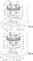
- eine Explosionsansicht der Ablaufanordnung nach
Figur 1 und2 mit dem Staufunktionsteil; - Fig. 5
- eine Explosionsansicht der Ablaufanordnung nach
Figur 1 und2 mit dem Notüberlauffunktionsteil; - Fig. 6
- eine Explosionsansicht der Ablaufanordnung mit dem Staufunktionsteil nach einer weiteren Variante;
- Fig. 7
- eine Explosionsansicht der Ablaufanordnung mit dem Notüberlauffunktionsteil nach der in
Figur 6 - Fig. 8
- eine Explosionsansicht der Ablaufanordnung mit dem Staufunktionsteil nach einer weiteren Variante; und
- Fig. 9
- eine Explosionsansicht der Ablaufanordnung mit dem Notüberlauffunktionsteil nach der in
Figur 8 gezeigten Variante.
- 1
- a perspective view of a drain arrangement comprising a drain device for roof drainage and an inlet device;
- 2
- a sectional view of the drain arrangement
figure 1 with a storage function part; - 3
- a sectional view of the drain arrangement
figure 1 with an emergency overflow function part; - 4
- an exploded view of the drain assembly
figure 1 and2 with the storage function part; - figure 5
- an exploded view of the drain assembly
figure 1 and2 with the emergency overflow function part; - 6
- an exploded view of the drain assembly with the accumulation function part after another variant;
- 7
- an exploded view of the flow arrangement with the emergency overflow function part according to in
figure 6 variant shown; - 8
- an exploded view of the flow arrangement with the storage function part according to a further variant; and
- 9
- an exploded view of the flow arrangement with the emergency overflow function part according to in
figure 8 shown variant.
In der
Die
Die Einlaufvorrichtung 1 umfasst ein Abdeckteil 4 zur Abdeckung des Rohreintritts 2 und ein Funktionsteil 5. Das Funktionsteil 5 ist unterhalb des Abdeckteils 4 angeordnet. Das Abdeckteil 4 ist mit einer Vielzahl von seitlichen Durchgängen 21 versehen, durch welche Wasser zur Ablaufvorrichtung 3 zuführbar ist. Das Abdeckteil 4 und das Funktionsteil 5 sind zu einem gebäudeseitig montierten Halteelement 6 der Ablaufvorrichtung 3 befestigbar. Das Funktionsteil 5 ist wahlweise ein Staufunktionsteil 7 oder ein Notüberlauffunktionsteil 8. Mit anderen Worten gesagt: Das Funktionsteil 5 kann aus der Gruppe von Staufunktionsteil 7 und Notüberlauffunktionsteil 8 ausgewählt werden.The
Typischerweise werden auf einem zu entwässernden Gebäude mindestens eine bzw. eine Mehrzahl von Ablaufanordnung(en) 29 mit dem Staufunktionsteil 7 und mindestens eine bzw. eine Mehrzahl von Ablaufanordnung(en) 29 mit dem Notüberlauffunktionsteil 8 angeordnet.Typically, at least one or one on a building to be drained A plurality of drain arrangement(s) 29 with the accumulation function part 7 and at least one or a plurality of drain arrangement(s) 29 with the emergency overflow function part 8 are arranged.
In der
In der
Die Stauhöhe S des Staufunktionsteils 7 ist, wie in den
Das Abdeckteil 4 umfasst in der gezeigten Ausführung einen Deckelabschnitt 39, von welchem sich seitlich eine Vielzahl von Stegen 38 weg erstrecken. Die Stege 38 sind beabstandet zueinander angeordnet. Durch den Abstand werden die Durchgänge 21 geschaffen.In the embodiment shown, the
Das Staufunktionsteil 7 und das Notüberlauffunktionsteil 8 verfügen über jeweils mindestens eine Befestigungsschnittstelle 15, über welche das jeweilige Funktionsteil 7, 8 zum Halteelement 6 der Ablaufvorrichtung 3 befestigbar ist. Die Befestigungsschnittstelle des Staufunktionsteils 7 ist dabei im Wesentlichen identisch zur Befestigungsschnittstelle des Notüberlauffunktionsteils 8 ausgebildet. Somit können beide Funktionsteile 7, 8 mit den gleichen Halteelementen 6 verbunden werden. Der Installateur kann vor Ort entscheiden, ob ein Staufunktionsteil 7 oder ein Notüberlauffunktionsteil 8 angeordnet werden soll, ohne dass an den Halteelementen 6 oder den Funktionsteilen 7, 8 Anpassungen vorgenommen werden müssen.The accumulation function part 7 and the emergency overflow function part 8 each have at least one
Von den
In der gezeigten Ausführungsform ist die besagte Befestigungsschnittstelle 15 Teil des Basisabschnittes 9. Die Befestigungsschnittstelle 15 wird hier als Öffnungen dargestellt, welches sich durch den Basisabschnitt 9 hindurch erstrecken. Über diese Öffnungen wird das Staufunktionsteil 7 bzw. das Notüberlauffunktionsteil 8 am Halteelement 6 gelagert. Das Halteelement 6 erstreckt sich dabei durch die Öffnung 15 hindurch.In the embodiment shown, said
Die Stauhöhe S wird durch die Oberseite 11 des scheibenförmigen Basisabschnittes 9 definiert. Das Wasser kann also bis zum Oberseite 11 des scheibenförmigen Basisabschnittes 9 ansteigen und erst dann wird das Ansaugen von Luft verhindert.The accumulation height S is defined by the
Beim Notüberlauffunktionsteil 8 weist der Basisabschnitt 9 eine den Einlauf 26 bereitstellende Durchlassöffnung 10 auf. Die Durchlassöffnung 10 wird hier durch eine Erhebung 12, die sich vom scheibenförmigen Basisabschnitt 9, erstreckt vollständig umgeben. Die Erhebung 12 umgibt die Durchlassöffnung 10 im Wesentlichen vollständig. Die Oberkante 13 der Erhebung 12 definiert dabei die Einlaufhöhe E. Die Erhebung 12 ist hier Teil eines Rohrabschnittes 14, welcher sich von der Oberkante 13 der Erhebung durch den scheibenförmigen Basisabschnitt 9 hindurch erstreckt und in Einbaulage, so wie in der
In den Explosionsansichten der
In den
In den
In den
Im vorliegenden Fall sind zwei Befestigungselemente 17 angeordnet. Es wäre auch denkbar nur ein oder mehr als zwei Befestigungselemente 17 vorzusehen. Die Zahl der Halteelement 9 entspricht vorzugsweise der Zahl der Befestigungselemente.In the present case, two
In der gezeigten Ausführungsform sind die Befestigungselemente 17 zweiteilig ausgebildet. Die Befestigungselement 17 umfassen dabei einen Aktuatorteil 22 und einen Verriegelungsteil 23. Das Aktuatorteil 22 steht dabei mit dem Verriegelungsteil 23 in Verbindung. Das Aktuatorteil 22 erstreckt sich dabei oberseitig zum Abdeckteil 4 sowie durch das Abdeckteil 4 hindurch und ist im Abdeckteil 4 drehbar gelagert. Das Aktuatorteil 22 kann von einem Installateur gut ergriffen werden. Das Verriegelungsteil 23 liegt unterseitig zum Abdeckteil 4 und arbeitet mit dem Halteelement 6 zusammen. Aktuatorteil 22 und Verriegelungsteil 23 werden vorzugsweise über eine Einrastverbindung miteinander verbunden. Das Befestigungselement 17 kann aber auch einteilig ausgebildet sein.In the embodiment shown, the
Oberhalb des Abdeckteils 4 weist hier das Befestigungselement 17 eine Grifflasche 30 auf. Die Grifflasche 30 kann vom Installateur zur Betätigung des Befestigungselementes ergriffen werden. Weiter erstreckt sich von der Oberseite des Abdeckteils 4 ein Kamm 31. Der Kamm 31 liegt hier zwischen zwei Befestigungselementen 17. Der Kamm 31 und die Grifflaschen 30 dienen dem Installateur der Signalisation der Stellung der Befestigungselemente. Liegen die Grifflaschen 30 fluchtend mit dem Kamm so befinden sich die Befestigungselemente 17 in der verriegelten Stellung. Liegt die Grifflasche 30 winklig zum Kamm 31 so liegt das Befestigungselement 17 in der entriegelten Stellung.Here, the
Unterseitig weist das Befestigungselement 17 hier noch einen Noppen 32 auf. Der Noppen 32 ragt dabei in eine Ausnehmung 33 in Basisabschnitt 9 ein. Durch die Paarung Noppen 32 und Ausnehmung 33 kann eine Führung zwischen dem Befestigungselement 17 und dem Staufunktionsteil 7 bzw. dem Notüberlauffunktionsteil 8 bereitgestellt werden. Die Führung hilft bei der Betätigung des Befestigungselementes aber auch bei der Positionierung des Abdeckteils 4.The
Weiter ist es vorteilhaft, wenn das Funktionsteil 7, 8 und das Abdeckteil 4 über Ausrichtelemente 27, 28 verfügen, wobei über die Ausrichtelemente 27, 28 das Abdeckteil 4 zum Funktionsteil 7, 8 ausrichtbar ist. In den gezeigten Ausführungsformen ist ein Ausrichtelement 27, 28 aus einer Paarung Erhebung und Ausnehmung bereitgestellt. Die Erhebung 27 wird durch die Stege 38 bereitgestellt, welche die Durchgänge 21 begrenzen und die Ausnehmung 28 erstreckt sich vom Rand in den Basisabschnitt 9 hinein.It is also advantageous if the functional part 7 , 8 and the
Wie in den
Vorzugsweise weist das Staufunktionsteils 7 eine strömungsoptimierte Form auf. Hierzu ist auf der Unterseite, die zur Ablaufvorrichtung 3 zugewandt ist, das Staufunktionsteil 7 entsprechend ausgebildet. Die strömungsoptimierten Elemente tragen das Bezugszeichen 34.
Claims (14)
- Drain assembly (29) for roof drainage, comprising a drain device (3) and an inlet device (1),wherein the drain device (3) has a pipe socket (18) and at least one retaining element (6), which latter is preferably in connection with the pipe socket (18), andwherein the inlet device comprises a cover part (4) for covering the pipe entrance (2), said cover part having lateral passages (21) through which water can be fed to the pipe entrance (2), and two functional parts (5), which can be arranged beneath the cover part (4),wherein one of the functional parts (5) is a build-up functional part (7) that defines a build-up height (S), and the other of the functional parts (5) is an emergency overflow functional part (8) having an inlet (26) that defines an infeed height (E), whereinboth the build-up functional part (7) and the emergency overflow functional part (8) and the cover part (4) are fastenable to said at least one retaining element (6), wherein selectively either the build-up functional part (7) or the emergency overflow functional part (8) is insertable in the drain assembly andwherein the build-up functional part (7) and the emergency overflow functional part (8) respectively comprise at least one fastening interface (15), via which the respective functional part (5, 7, 8) are fastenable to the retaining element (6), wherein the fastening interface of the build-up functional part (7) and the fastening interface of the emergency overflow functional part (8) are configured substantially identically to each other.
- Drain assembly (29) as claimed in claim 1, characterized in that both the build-up functional part (7) and the emergency overflow functional part (8) are held on the retaining element (6) by the cover part.
- Drain assembly (29) as claimed in one of the preceding claims, characterized in that the build-up functional part (7) and the emergency overflow functional part (8) respectively have a disk-shaped base portion (9), wherein, in the assembled state, the disk-shaped base portion (9) of the build-up functional part (7) and that of the emergency overflow functional part (8) lie preferably at the same height.
- Drain assembly (29) as claimed in claim 3, characterized in that the base portion (9) can comprise and/or receive and/or provide at least parts of the fastening interface (15).
- Drain assembly (29) as claimed in one of the preceding claims, characterized in that the fastening interface of the build-up functional part and the fastening interface of the emergency overflow part has the form of an opening (15), which is arranged in the same location or in the same position on the build-up functional part (7) and on the emergency overflow functional part (8).
- Drain assembly (29) as claimed in claim 5, characterized in that the opening (15) is arranged in the disk-shaped base portion (9), wherein the disk-shaped base portion (9) is of planar configuration in the region of the opening (15), or wherein the disk-shaped base portion (9) has in the region of the opening (15) a bulge (16) extending away from the cover part (4), wherein the opening (15) is arranged in the bulge (16).
- Drain assembly (29) as claimed in one of the preceding claims, characterized in that at least one fastening element (17) is displaceably mounted on the cover part (4), with which fastening element (17) the cover part (4) is fastenable to the retaining element (6).
- Drain assembly (29) as claimed in claim 7, characterized in that the fastening element (17) is of single-part configuration, or of multipart configuration comprising an actuator part (22) and a locking part (23), which are in connection with each other, wherein the actuator part (22) lies at least partially on the top side of the cover part (4) and the locking part (23) lies at least partially on the bottom side of the cover part (4).
- Drain assembly (29) as claimed in one of the preceding claims, characterized in that the retaining element (9) is configured as a pin (19) having a notch, in particular a circumferential groove (20), wherein the cover part (4), in particular with the fastening element (17), can be fastened to the retaining element via the notch.
- Drain assembly (29) as claimed in one of the preceding claims, in particular as claimed in claim 9, characterized in that the retaining element (9) has a bearing surface (24), on which the functional part (5), in particular with the bottom side (25) of the base portion (9), is supported, wherein the bearing surface (24) is arranged at a distance from the notch (20), which distance preferably corresponds to the thickness of the base portion (9).
- Drain assembly (29) as claimed in one of the preceding claims, characterized in that the functional part (5, 7, 8) and the cover part (4) possess alignment elements (27, 28), in particular recesses (27) and elevations (28), wherein, via the alignment elements (27, 28), the cover part (4) can be aligned to the functional part (5, 7, 8).
- Drain assembly (29) as claimed in one of the preceding claims, characterizedin that, in the case of the build-up functional part (7), the top side (11) of the disk-shaped base portion (9) defines the build-up height (S), and/orin that the emergency overflow functional part (8) the base portion (9) comprises a passage opening (10), which provides the inlet (26), and an elevation (12), which extends from the disk-shaped base portion (9) fully around the passage opening (10) and the top edge (13) of which defines the infeed height.
- Drain assembly (29) as claimed in claim 12, characterized in that the elevation (12) is part of a pipe section (14), which extends from the top edge (13) of the elevation (12) through the disk-shaped base portion (9) and, in the installation position, projects into the pipe entrance (2) of the drain device (3).
- Drain assembly (29) as claimed in one of the preceding claims 13 and 14, characterized in that between the bottom side of the cover part (4) and the elevation (26) a free interspace (37) is present, through which the water to be led off can be fed to the inlet (26), and/orin that the build-up functional part (7) is arranged at a distance from the pipe socket (18), so that between the pipe entrance (2) and the build-up plate is created a free interspace (35), through which water can flow to the pipe socket (18), and/orin that the emergency overflow functional part (8) is arranged in such a way relative to the pipe socket (18) that water can flow into the pipe socket solely via the inlet (26) of the emergency overflow functional part (8).
Priority Applications (3)
| Application Number | Priority Date | Filing Date | Title |
|---|---|---|---|
| PL19157327T PL3505703T3 (en) | 2015-06-12 | 2015-06-12 | Drain assembly |
| DK19157327.8T DK3505703T3 (en) | 2015-06-12 | 2015-06-12 | Drain device |
| EP19157327.8A EP3505703B1 (en) | 2015-06-12 | 2015-06-12 | Drain assembly |
Applications Claiming Priority (2)
| Application Number | Priority Date | Filing Date | Title |
|---|---|---|---|
| EP15171865.7A EP3103937B1 (en) | 2015-06-12 | 2015-06-12 | Drain assembly |
| EP19157327.8A EP3505703B1 (en) | 2015-06-12 | 2015-06-12 | Drain assembly |
Related Parent Applications (2)
| Application Number | Title | Priority Date | Filing Date |
|---|---|---|---|
| EP15171865.7A Division-Into EP3103937B1 (en) | 2015-06-12 | 2015-06-12 | Drain assembly |
| EP15171865.7A Division EP3103937B1 (en) | 2015-06-12 | 2015-06-12 | Drain assembly |
Publications (2)
| Publication Number | Publication Date |
|---|---|
| EP3505703A1 EP3505703A1 (en) | 2019-07-03 |
| EP3505703B1 true EP3505703B1 (en) | 2022-01-26 |
Family
ID=53397912
Family Applications (2)
| Application Number | Title | Priority Date | Filing Date |
|---|---|---|---|
| EP15171865.7A Active EP3103937B1 (en) | 2015-06-12 | 2015-06-12 | Drain assembly |
| EP19157327.8A Active EP3505703B1 (en) | 2015-06-12 | 2015-06-12 | Drain assembly |
Family Applications Before (1)
| Application Number | Title | Priority Date | Filing Date |
|---|---|---|---|
| EP15171865.7A Active EP3103937B1 (en) | 2015-06-12 | 2015-06-12 | Drain assembly |
Country Status (6)
| Country | Link |
|---|---|
| EP (2) | EP3103937B1 (en) |
| CN (1) | CN107646059A (en) |
| AU (1) | AU2016274373B2 (en) |
| DK (2) | DK3103937T3 (en) |
| PL (2) | PL3103937T3 (en) |
| WO (1) | WO2016198234A1 (en) |
Families Citing this family (1)
| Publication number | Priority date | Publication date | Assignee | Title |
|---|---|---|---|---|
| US10907356B2 (en) * | 2018-06-19 | 2021-02-02 | RPH Intellectual Holdings, LLC | Roof drain |
Family Cites Families (6)
| Publication number | Priority date | Publication date | Assignee | Title |
|---|---|---|---|---|
| US1762838A (en) * | 1929-01-23 | 1930-06-10 | Shand & Jurs Company | Roof drain |
| US2121220A (en) * | 1936-12-18 | 1938-06-21 | Paul Dickinson Inc | Roof drain |
| EP1013843B1 (en) * | 1998-12-24 | 2003-08-20 | Wolfgang Dipl.-Ing. Vahlbrauk | Free-head water drainage |
| IT1395999B1 (en) * | 2009-03-10 | 2012-11-09 | Valsir Spa | WATER DRAIN POCKET, IN PARTICULAR FOR SYSTEMS WITH A SIPHONIC EFFECT OF ROOF DRAINAGE |
| IT1403885B1 (en) * | 2010-11-26 | 2013-11-08 | Valsir Spa | DRAINAGE DEVICE FOR WATER DRAIN PITCHES, IN PARTICULAR FOR DRAINAGE SYSTEMS OF BUILDING ROOFS, AND WATER DRAINAGE COCKPIT PROVIDED WITH SUCH AN INTERLOCKING DEVICE |
| DK2703576T3 (en) * | 2012-09-03 | 2015-10-05 | Geberit Int Ag | Cover means for covering rørindgangen to a drainage element of a drainage system |
-
2015
- 2015-06-12 EP EP15171865.7A patent/EP3103937B1/en active Active
- 2015-06-12 DK DK15171865.7T patent/DK3103937T3/en active
- 2015-06-12 DK DK19157327.8T patent/DK3505703T3/en active
- 2015-06-12 EP EP19157327.8A patent/EP3505703B1/en active Active
- 2015-06-12 PL PL15171865T patent/PL3103937T3/en unknown
- 2015-06-12 PL PL19157327T patent/PL3505703T3/en unknown
-
2016
- 2016-05-13 AU AU2016274373A patent/AU2016274373B2/en active Active
- 2016-05-13 WO PCT/EP2016/060877 patent/WO2016198234A1/en active Application Filing
- 2016-05-13 CN CN201680029898.2A patent/CN107646059A/en active Pending
Non-Patent Citations (1)
| Title |
|---|
| None * |
Also Published As
| Publication number | Publication date |
|---|---|
| DK3103937T3 (en) | 2020-03-30 |
| DK3505703T3 (en) | 2022-04-19 |
| CN107646059A (en) | 2018-01-30 |
| EP3103937B1 (en) | 2020-01-01 |
| WO2016198234A1 (en) | 2016-12-15 |
| EP3505703A1 (en) | 2019-07-03 |
| EP3103937A1 (en) | 2016-12-14 |
| AU2016274373B2 (en) | 2021-08-05 |
| PL3505703T3 (en) | 2022-04-25 |
| PL3103937T3 (en) | 2020-06-29 |
| AU2016274373A1 (en) | 2017-11-16 |
Similar Documents
| Publication | Publication Date | Title |
|---|---|---|
| DE112009005518B4 (en) | Position compensating vehicle gutter molding fixture | |
| EP0442135B1 (en) | Device for bringing together a plurality of infusions and/or injections | |
| EP1976576A2 (en) | Fastening device for a drainage container | |
| EP3024990A1 (en) | Drain device | |
| EP2995732B1 (en) | Façade gutter | |
| DE202004015811U1 (en) | Fastening device for at least one solar panel | |
| EP3505703B1 (en) | Drain assembly | |
| EP3776772B1 (en) | Separating web for an energy chain | |
| EP1826334B1 (en) | Emergency overflow | |
| EP3272954B1 (en) | Drain assembly | |
| WO2014037413A1 (en) | Drain assembly and method for arranging a drain assembly on a drain connection of a sink | |
| EP2703576B1 (en) | Covering device for covering the pipe entry of a drain element of a drainage system | |
| EP2651712B1 (en) | Wiper blade device | |
| EP3272955B1 (en) | Siphon assembly | |
| EP2981241B1 (en) | Fluid valve and fluid connection system | |
| EP0758038A1 (en) | Gully cleaning device | |
| DE202009007897U1 (en) | Water pipe sleeve | |
| EP2641306B1 (en) | Exhaust chute for an overvoltage arrester, overvoltage arrester, and set of overvoltage arresters arranged in a row | |
| DE102015102348B4 (en) | Device fan cover | |
| DE20318617U1 (en) | inlet housing | |
| EP0798475B1 (en) | Element for the fixation of a mat | |
| EP2735661A1 (en) | Sanitary basin | |
| WO2021105104A1 (en) | Gutter system, cover unit and securing element | |
| DE102021111651A1 (en) | drain filter | |
| DE102016103728B4 (en) | Pipe unit and system |
Legal Events
| Date | Code | Title | Description |
|---|---|---|---|
| PUAI | Public reference made under article 153(3) epc to a published international application that has entered the european phase |
Free format text: ORIGINAL CODE: 0009012 |
|
| STAA | Information on the status of an ep patent application or granted ep patent |
Free format text: STATUS: THE APPLICATION HAS BEEN PUBLISHED |
|
| AC | Divisional application: reference to earlier application |
Ref document number: 3103937 Country of ref document: EP Kind code of ref document: P |
|
| AK | Designated contracting states |
Kind code of ref document: A1 Designated state(s): AL AT BE BG CH CY CZ DE DK EE ES FI FR GB GR HR HU IE IS IT LI LT LU LV MC MK MT NL NO PL PT RO RS SE SI SK SM TR |
|
| STAA | Information on the status of an ep patent application or granted ep patent |
Free format text: STATUS: REQUEST FOR EXAMINATION WAS MADE |
|
| 17P | Request for examination filed |
Effective date: 20191108 |
|
| RBV | Designated contracting states (corrected) |
Designated state(s): AL AT BE BG CH CY CZ DE DK EE ES FI FR GB GR HR HU IE IS IT LI LT LU LV MC MK MT NL NO PL PT RO RS SE SI SK SM TR |
|
| STAA | Information on the status of an ep patent application or granted ep patent |
Free format text: STATUS: EXAMINATION IS IN PROGRESS |
|
| 17Q | First examination report despatched |
Effective date: 20200128 |
|
| STAA | Information on the status of an ep patent application or granted ep patent |
Free format text: STATUS: EXAMINATION IS IN PROGRESS |
|
| GRAP | Despatch of communication of intention to grant a patent |
Free format text: ORIGINAL CODE: EPIDOSNIGR1 |
|
| STAA | Information on the status of an ep patent application or granted ep patent |
Free format text: STATUS: GRANT OF PATENT IS INTENDED |
|
| RIN1 | Information on inventor provided before grant (corrected) |
Inventor name: HAUSHEER, ROMAN |
|
| INTG | Intention to grant announced |
Effective date: 20210709 |
|
| GRAJ | Information related to disapproval of communication of intention to grant by the applicant or resumption of examination proceedings by the epo deleted |
Free format text: ORIGINAL CODE: EPIDOSDIGR1 |
|
| STAA | Information on the status of an ep patent application or granted ep patent |
Free format text: STATUS: EXAMINATION IS IN PROGRESS |
|
| GRAP | Despatch of communication of intention to grant a patent |
Free format text: ORIGINAL CODE: EPIDOSNIGR1 |
|
| STAA | Information on the status of an ep patent application or granted ep patent |
Free format text: STATUS: GRANT OF PATENT IS INTENDED |
|
| GRAS | Grant fee paid |
Free format text: ORIGINAL CODE: EPIDOSNIGR3 |
|
| GRAA | (expected) grant |
Free format text: ORIGINAL CODE: 0009210 |
|
| STAA | Information on the status of an ep patent application or granted ep patent |
Free format text: STATUS: THE PATENT HAS BEEN GRANTED |
|
| INTG | Intention to grant announced |
Effective date: 20211203 |
|
| AC | Divisional application: reference to earlier application |
Ref document number: 3103937 Country of ref document: EP Kind code of ref document: P |
|
| AK | Designated contracting states |
Kind code of ref document: B1 Designated state(s): AL AT BE BG CH CY CZ DE DK EE ES FI FR GB GR HR HU IE IS IT LI LT LU LV MC MK MT NL NO PL PT RO RS SE SI SK SM TR |
|
| REG | Reference to a national code |
Ref country code: GB Ref legal event code: FG4D Free format text: NOT ENGLISH |
|
| REG | Reference to a national code |
Ref country code: CH Ref legal event code: EP |
|
| REG | Reference to a national code |
Ref country code: AT Ref legal event code: REF Ref document number: 1465409 Country of ref document: AT Kind code of ref document: T Effective date: 20220215 |
|
| REG | Reference to a national code |
Ref country code: IE Ref legal event code: FG4D Free format text: LANGUAGE OF EP DOCUMENT: GERMAN |
|
| REG | Reference to a national code |
Ref country code: DE Ref legal event code: R096 Ref document number: 502015015614 Country of ref document: DE |
|
| REG | Reference to a national code |
Ref country code: FI Ref legal event code: FGE |
|
| REG | Reference to a national code |
Ref country code: SE Ref legal event code: TRGR |
|
| REG | Reference to a national code |
Ref country code: NL Ref legal event code: FP |
|
| REG | Reference to a national code |
Ref country code: DK Ref legal event code: T3 Effective date: 20220411 |
|
| REG | Reference to a national code |
Ref country code: LT Ref legal event code: MG9D |
|
| PG25 | Lapsed in a contracting state [announced via postgrant information from national office to epo] |
Ref country code: RS Free format text: LAPSE BECAUSE OF FAILURE TO SUBMIT A TRANSLATION OF THE DESCRIPTION OR TO PAY THE FEE WITHIN THE PRESCRIBED TIME-LIMIT Effective date: 20220126 Ref country code: PT Free format text: LAPSE BECAUSE OF FAILURE TO SUBMIT A TRANSLATION OF THE DESCRIPTION OR TO PAY THE FEE WITHIN THE PRESCRIBED TIME-LIMIT Effective date: 20220526 Ref country code: NO Free format text: LAPSE BECAUSE OF FAILURE TO SUBMIT A TRANSLATION OF THE DESCRIPTION OR TO PAY THE FEE WITHIN THE PRESCRIBED TIME-LIMIT Effective date: 20220426 Ref country code: LT Free format text: LAPSE BECAUSE OF FAILURE TO SUBMIT A TRANSLATION OF THE DESCRIPTION OR TO PAY THE FEE WITHIN THE PRESCRIBED TIME-LIMIT Effective date: 20220126 Ref country code: HR Free format text: LAPSE BECAUSE OF FAILURE TO SUBMIT A TRANSLATION OF THE DESCRIPTION OR TO PAY THE FEE WITHIN THE PRESCRIBED TIME-LIMIT Effective date: 20220126 Ref country code: ES Free format text: LAPSE BECAUSE OF FAILURE TO SUBMIT A TRANSLATION OF THE DESCRIPTION OR TO PAY THE FEE WITHIN THE PRESCRIBED TIME-LIMIT Effective date: 20220126 Ref country code: BG Free format text: LAPSE BECAUSE OF FAILURE TO SUBMIT A TRANSLATION OF THE DESCRIPTION OR TO PAY THE FEE WITHIN THE PRESCRIBED TIME-LIMIT Effective date: 20220426 |
|
| PG25 | Lapsed in a contracting state [announced via postgrant information from national office to epo] |
Ref country code: LV Free format text: LAPSE BECAUSE OF FAILURE TO SUBMIT A TRANSLATION OF THE DESCRIPTION OR TO PAY THE FEE WITHIN THE PRESCRIBED TIME-LIMIT Effective date: 20220126 Ref country code: GR Free format text: LAPSE BECAUSE OF FAILURE TO SUBMIT A TRANSLATION OF THE DESCRIPTION OR TO PAY THE FEE WITHIN THE PRESCRIBED TIME-LIMIT Effective date: 20220427 |
|
| PG25 | Lapsed in a contracting state [announced via postgrant information from national office to epo] |
Ref country code: IS Free format text: LAPSE BECAUSE OF FAILURE TO SUBMIT A TRANSLATION OF THE DESCRIPTION OR TO PAY THE FEE WITHIN THE PRESCRIBED TIME-LIMIT Effective date: 20220526 |
|
| REG | Reference to a national code |
Ref country code: DE Ref legal event code: R097 Ref document number: 502015015614 Country of ref document: DE |
|
| PG25 | Lapsed in a contracting state [announced via postgrant information from national office to epo] |
Ref country code: SM Free format text: LAPSE BECAUSE OF FAILURE TO SUBMIT A TRANSLATION OF THE DESCRIPTION OR TO PAY THE FEE WITHIN THE PRESCRIBED TIME-LIMIT Effective date: 20220126 Ref country code: SK Free format text: LAPSE BECAUSE OF FAILURE TO SUBMIT A TRANSLATION OF THE DESCRIPTION OR TO PAY THE FEE WITHIN THE PRESCRIBED TIME-LIMIT Effective date: 20220126 Ref country code: RO Free format text: LAPSE BECAUSE OF FAILURE TO SUBMIT A TRANSLATION OF THE DESCRIPTION OR TO PAY THE FEE WITHIN THE PRESCRIBED TIME-LIMIT Effective date: 20220126 Ref country code: EE Free format text: LAPSE BECAUSE OF FAILURE TO SUBMIT A TRANSLATION OF THE DESCRIPTION OR TO PAY THE FEE WITHIN THE PRESCRIBED TIME-LIMIT Effective date: 20220126 Ref country code: CZ Free format text: LAPSE BECAUSE OF FAILURE TO SUBMIT A TRANSLATION OF THE DESCRIPTION OR TO PAY THE FEE WITHIN THE PRESCRIBED TIME-LIMIT Effective date: 20220126 |
|
| PG25 | Lapsed in a contracting state [announced via postgrant information from national office to epo] |
Ref country code: AL Free format text: LAPSE BECAUSE OF FAILURE TO SUBMIT A TRANSLATION OF THE DESCRIPTION OR TO PAY THE FEE WITHIN THE PRESCRIBED TIME-LIMIT Effective date: 20220126 |
|
| PLBE | No opposition filed within time limit |
Free format text: ORIGINAL CODE: 0009261 |
|
| STAA | Information on the status of an ep patent application or granted ep patent |
Free format text: STATUS: NO OPPOSITION FILED WITHIN TIME LIMIT |
|
| 26N | No opposition filed |
Effective date: 20221027 |
|
| PG25 | Lapsed in a contracting state [announced via postgrant information from national office to epo] |
Ref country code: MC Free format text: LAPSE BECAUSE OF FAILURE TO SUBMIT A TRANSLATION OF THE DESCRIPTION OR TO PAY THE FEE WITHIN THE PRESCRIBED TIME-LIMIT Effective date: 20220126 |
|
| REG | Reference to a national code |
Ref country code: BE Ref legal event code: MM Effective date: 20220630 |
|
| PG25 | Lapsed in a contracting state [announced via postgrant information from national office to epo] |
Ref country code: SI Free format text: LAPSE BECAUSE OF FAILURE TO SUBMIT A TRANSLATION OF THE DESCRIPTION OR TO PAY THE FEE WITHIN THE PRESCRIBED TIME-LIMIT Effective date: 20220126 |
|
| GBPC | Gb: european patent ceased through non-payment of renewal fee |
Effective date: 20220612 |
|
| PG25 | Lapsed in a contracting state [announced via postgrant information from national office to epo] |
Ref country code: LU Free format text: LAPSE BECAUSE OF NON-PAYMENT OF DUE FEES Effective date: 20220612 Ref country code: IE Free format text: LAPSE BECAUSE OF NON-PAYMENT OF DUE FEES Effective date: 20220612 Ref country code: FR Free format text: LAPSE BECAUSE OF NON-PAYMENT OF DUE FEES Effective date: 20220630 |
|
| PG25 | Lapsed in a contracting state [announced via postgrant information from national office to epo] |
Ref country code: GB Free format text: LAPSE BECAUSE OF NON-PAYMENT OF DUE FEES Effective date: 20220612 Ref country code: BE Free format text: LAPSE BECAUSE OF NON-PAYMENT OF DUE FEES Effective date: 20220630 |
|
| P01 | Opt-out of the competence of the unified patent court (upc) registered |
Effective date: 20230516 |
|
| PGFP | Annual fee paid to national office [announced via postgrant information from national office to epo] |
Ref country code: NL Payment date: 20230620 Year of fee payment: 9 Ref country code: DK Payment date: 20230622 Year of fee payment: 9 Ref country code: DE Payment date: 20230620 Year of fee payment: 9 |
|
| PGFP | Annual fee paid to national office [announced via postgrant information from national office to epo] |
Ref country code: SE Payment date: 20230620 Year of fee payment: 9 Ref country code: PL Payment date: 20230524 Year of fee payment: 9 Ref country code: FI Payment date: 20230621 Year of fee payment: 9 Ref country code: AT Payment date: 20230621 Year of fee payment: 9 |
|
| PGFP | Annual fee paid to national office [announced via postgrant information from national office to epo] |
Ref country code: IT Payment date: 20230621 Year of fee payment: 9 Ref country code: CH Payment date: 20230702 Year of fee payment: 9 |
|
| PG25 | Lapsed in a contracting state [announced via postgrant information from national office to epo] |
Ref country code: HU Free format text: LAPSE BECAUSE OF FAILURE TO SUBMIT A TRANSLATION OF THE DESCRIPTION OR TO PAY THE FEE WITHIN THE PRESCRIBED TIME-LIMIT; INVALID AB INITIO Effective date: 20150612 |
|
| PG25 | Lapsed in a contracting state [announced via postgrant information from national office to epo] |
Ref country code: MK Free format text: LAPSE BECAUSE OF FAILURE TO SUBMIT A TRANSLATION OF THE DESCRIPTION OR TO PAY THE FEE WITHIN THE PRESCRIBED TIME-LIMIT Effective date: 20220126 Ref country code: CY Free format text: LAPSE BECAUSE OF FAILURE TO SUBMIT A TRANSLATION OF THE DESCRIPTION OR TO PAY THE FEE WITHIN THE PRESCRIBED TIME-LIMIT Effective date: 20220126 |