EP3504435B1 - Hydrostatisches system und pumpstation für eine öl- oder gas-pipeline - Google Patents
Hydrostatisches system und pumpstation für eine öl- oder gas-pipeline Download PDFInfo
- Publication number
- EP3504435B1 EP3504435B1 EP17745164.8A EP17745164A EP3504435B1 EP 3504435 B1 EP3504435 B1 EP 3504435B1 EP 17745164 A EP17745164 A EP 17745164A EP 3504435 B1 EP3504435 B1 EP 3504435B1
- Authority
- EP
- European Patent Office
- Prior art keywords
- hydraulic
- pump
- hydraulic motor
- pressure
- motor
- Prior art date
- Legal status (The legal status is an assumption and is not a legal conclusion. Google has not performed a legal analysis and makes no representation as to the accuracy of the status listed.)
- Active
Links
Images

Classifications
-
- F—MECHANICAL ENGINEERING; LIGHTING; HEATING; WEAPONS; BLASTING
- F04—POSITIVE - DISPLACEMENT MACHINES FOR LIQUIDS; PUMPS FOR LIQUIDS OR ELASTIC FLUIDS
- F04B—POSITIVE-DISPLACEMENT MACHINES FOR LIQUIDS; PUMPS
- F04B17/00—Pumps characterised by combination with, or adaptation to, specific driving engines or motors
- F04B17/05—Pumps characterised by combination with, or adaptation to, specific driving engines or motors driven by internal-combustion engines
-
- F—MECHANICAL ENGINEERING; LIGHTING; HEATING; WEAPONS; BLASTING
- F02—COMBUSTION ENGINES; HOT-GAS OR COMBUSTION-PRODUCT ENGINE PLANTS
- F02N—STARTING OF COMBUSTION ENGINES; STARTING AIDS FOR SUCH ENGINES, NOT OTHERWISE PROVIDED FOR
- F02N15/00—Other power-operated starting apparatus; Component parts, details, or accessories, not provided for in, or of interest apart from groups F02N5/00 - F02N13/00
- F02N15/02—Gearing between starting-engines and started engines; Engagement or disengagement thereof
- F02N15/022—Gearing between starting-engines and started engines; Engagement or disengagement thereof the starter comprising an intermediate clutch
-
- F—MECHANICAL ENGINEERING; LIGHTING; HEATING; WEAPONS; BLASTING
- F02—COMBUSTION ENGINES; HOT-GAS OR COMBUSTION-PRODUCT ENGINE PLANTS
- F02N—STARTING OF COMBUSTION ENGINES; STARTING AIDS FOR SUCH ENGINES, NOT OTHERWISE PROVIDED FOR
- F02N7/00—Starting apparatus having fluid-driven auxiliary engines or apparatus
- F02N7/06—Starting apparatus having fluid-driven auxiliary engines or apparatus the engines being of reciprocating-piston type
-
- F—MECHANICAL ENGINEERING; LIGHTING; HEATING; WEAPONS; BLASTING
- F04—POSITIVE - DISPLACEMENT MACHINES FOR LIQUIDS; PUMPS FOR LIQUIDS OR ELASTIC FLUIDS
- F04B—POSITIVE-DISPLACEMENT MACHINES FOR LIQUIDS; PUMPS
- F04B23/00—Pumping installations or systems
-
- F—MECHANICAL ENGINEERING; LIGHTING; HEATING; WEAPONS; BLASTING
- F15—FLUID-PRESSURE ACTUATORS; HYDRAULICS OR PNEUMATICS IN GENERAL
- F15B—SYSTEMS ACTING BY MEANS OF FLUIDS IN GENERAL; FLUID-PRESSURE ACTUATORS, e.g. SERVOMOTORS; DETAILS OF FLUID-PRESSURE SYSTEMS, NOT OTHERWISE PROVIDED FOR
- F15B1/00—Installations or systems with accumulators; Supply reservoir or sump assemblies
- F15B1/02—Installations or systems with accumulators
Definitions
- Hydrostatic system and pumping station for an oil or gas pipeline The invention relates generally to a hydrostatic system according to the preamble of claim 1 and in particular to a pumping station for an oil or gas pipeline with such a hydrostatic system, the hydrostatic system for starting up an internal combustion engine of the pump station is used.
- internal combustion engines for example large gas engines, are used which drive one or more feed pumps for conveying the medium - oil or gas - through the pipeline.
- gas engines have, for example, an output of 1800 to 11000 hp and a starting torque of, for example, 32000 Nm at 4000 hp. The starting speed can then be, for example, 65 rpm and should be reached within 30 seconds.
- the medium conveyed through the pipeline in particular gas, is conventionally used to start the internal combustion engine. This is no longer desirable for environmental reasons.
- the present invention is based on the object of specifying a hydrostatic system which avoids the disadvantages mentioned and enables efficient control of the hydraulic pressure for a consumer and / or the drive power of a hydraulic motor, for example for an internal combustion engine in particular in the pumping station or compressor station of an oil or gas pipeline.
- the solution according to the invention makes it possible to achieve a pressure reduction in the hydrostatic system by using an additional hydraulic motor which drives a hydraulic pump which in turn conveys hydraulic medium to the pressure side of the consumer and / or the first hydraulic motor, so that the volume flow of the hydraulic medium through the first hydraulic motor and / or the consumer is increased and the energy contained in this hydraulic medium flow conveyed by means of the hydraulic pump remains in the hydrostatic system as hydraulic energy.
- a higher efficiency than with a variably adjustable throttle diaphragm can be achieved and undesirable forces and / or torques, which can lead to strong accelerations and can have a dangerous effect, are avoided due to the precise controllability.
- the hydraulic pump is used to supply the first hydraulic motor and / or the consumer with pressurized hydraulic medium.
- a hydrostatic system has a hydraulic pressure source, as well as a first hydraulic motor that has an output shaft that forms a mechanical power output of the hydrostatic system, and / or at least one consumer that is pressurized with pressurized hydraulic medium from the pressure source.
- the first hydraulic motor is used to drive it and / or at least one consumer is connected to the pressure source with a pressure line to pressurize it.
- a hydraulic motor-pump unit comprising an additional hydraulic motor (in addition to the first hydraulic motor and / or in addition to the at least one consumer) and a hydraulic pump, which are in a drive connection with one another, such that the hydraulic pump from the additional hydraulic motor is drivable.
- the additional hydraulic motor is connected to drive it in series with the first hydraulic motor and / or the at least one consumer at the pressure source and the hydraulic pump has a pressure side with which it is connected to the pressure line.
- the hydraulic pump thus conveys pressurized hydraulic medium, in particular from a hydraulic pressure source such as a tank, into the pressure line, which is why this hydraulic medium is in turn available for the first hydraulic motor and / or the at least one consumer.
- a hydraulic reservoir in particular in the form of a hydraulic tank or hydraulic sump, is preferably provided, from which the hydraulic pressure source is fed by means of at least one charge pump.
- the charge pump can do this be operated to work directly as a hydraulic pressure source, which provides the pressurized hydraulic medium without intermediate storage.
- the hydraulic pressure source has at least one pressure accumulator, to which the charge pump is connected with a charge pump pressure side for feeding hydraulic medium into the pressure accumulator.
- an electric motor is preferably provided for driving the charge pump.
- the hydraulic pump preferably has a suction side which is connected to the hydraulic supply by means of a suction line.
- the pressure accumulator and the motor-pump unit can be supplied from the same hydraulic supply.
- the hydraulic pressure source has a multiplicity of pressure accumulators.
- pressure accumulators can be filled simultaneously or in succession by means of the at least one charge pump.
- pressure accumulators can also be emptied simultaneously or in succession to supply the first hydraulic motor and / or the at least one consumer with pressurized hydraulic medium.
- a variably adjustable throttle valve is provided in the pressure line for regulating the pressure in the pressure line on the input side or output side of the first hydraulic motor and / or on the input side or output side of the at least one consumer.
- a variably adjustable throttle valve for regulating the pressure in the pressure line can be used on the input or output side of the additional hydraulic motor can be provided.
- the additional hydraulic motor and the hydraulic pump for driving the hydraulic pump can be rigidly coupled to one another. Due to the motor-pump unit, the adjustable throttle valve can be made smaller than conventional and thus generate less dissipation energy.
- the drive connection between the additional hydraulic motor and the hydraulic pump is preferably made purely mechanically, in particular by the rigid coupling mentioned, which can be produced, for example, by a shaft which carries the impellers of the additional hydraulic motor and the hydraulic pump or is connected to them in a rotationally rigid manner.
- At least one of the two units - the additional hydraulic motor and / or the hydraulic pump - can be designed as an adjustable unit - variable motor and / or variable pump - that is, with variably adjustable delivery volume per revolution, in particular with variably adjustable stroke volume, in the embodiment of the corresponding unit as a reciprocating piston machine.
- a transmission gear with a variably adjustable speed ratio is provided in the drive connection between the additional hydraulic motor and the hydraulic clutch.
- the speed of the hydraulic pump is thus decoupled from the speed of the additional hydraulic motor, so that by regulating the speed it is possible to regulate the power consumption of the motor-pump unit.
- the throttle valve provided in the pressure line can be made smaller and can only be used for controls outside the control range of the speed control, or can even be saved entirely.
- the throttle valve can generally be dispensed with completely, and the entire control range can be covered solely by the variable adjustment of the delivery volume per revolution of both units.
- At least one further hydraulic motor and / or at least one consumer is preferably provided, in which the hydraulic medium is expanded or consumed, these units also being connected or connectable to the pressure line.
- an electric generator or an electric motor generator for energy storage or reversible energy storage is connected to the hydraulic motor-pump unit.
- the generator or the electric motor generator correspondingly converts drive power into electrical energy, so that this can be stored in an electrical energy store or can be used for another electrical unit. If a motor generator is provided, electrical energy can accordingly be converted into drive power from the energy store in order to drive the hydraulic motor-pump unit, that is to say the additional hydraulic motor and / or the hydraulic pump.
- the additional hydraulic motor can be operated as a hydraulic pump with or without reversing the direction of flow of the hydraulic medium flowing through it.
- the drive can take place, for example, by the electric motor generator mentioned or by the fact that the hydraulic pump can also be switched over so that it can be operated by a motor.
- the hydraulic pump can be operated by a motor, it can also be used to dissipate pressure energy from the hydrostatic system.
- the additional hydraulic motor can be operated as a hydraulic pump, the differential pressure on the first hydraulic motor and / or on the at least one consumer can thereby be increased.
- the additional hydraulic motor can also be used in pump operation to reduce the differential pressure.
- the additional hydraulic motor in pump operation can also be used to supply a subsystem of the hydrostatic system with a higher pressure of the hydraulic medium, so that a corresponding high-pressure pump can be dispensed with.
- a pump station according to the invention for an oil or gas pipeline has at least one feed pump in order to convey the oil or gas through the pipeline. Furthermore, at least one internal combustion engine is provided for driving the at least one feed pump.
- the internal combustion engine is connected to a hydrostatic system according to the invention, which is then designed as a drive system with a first hydraulic motor, the internal combustion engine being in driving connection with the first hydraulic motor or being switchable in such a way when it starts up. Accordingly, the internal combustion engine is switched or switchable into a drive connection with the output shaft of the first hydraulic motor. Alternatively, the internal combustion engine can also be acted upon as a consumer with pressurized hydraulic medium from the hydraulic pump.
- FIG. 1 shows a hydrostatic system according to the invention, which is used to drive an internal combustion engine, in particular a pumping station for an oil or gas pipeline.
- the invention is not limited to this.
- the hydrostatic system for starting the internal combustion engine 1 has a hydraulic motor 10 which can be coupled to the internal combustion engine 1 via a clutch 6.
- a clutch 6 In addition or instead of the clutch 6, one or more gear ratios and / or at least one gear can also be provided.
- the hydraulic motor 10 is fed from a hydraulic pressure source 11.
- the pressure source 11 comprises a pressure accumulator 12, here in the form of a accumulator with a gas tensioning device.
- a further gas-filled, in particular nitrogen-filled, gas store 13 is preferably connected to the pressure store 12 and is connected to the gas side of the pressure store 12 or can be switched into such a flow-conducting connection. So that the gas spring of the Pressure accumulator are increased and the maximum possible hydraulic medium supply in the pressure accumulator 12 increases with a constant pressure level, in particular with a constant preload pressure of the gas spring and with a constant maximum accumulator pressure.
- the gas reservoir 13 has, for example, the same volume as the pressure reservoir 12.
- FIG. 1 is indicated schematically that in addition to the first hydraulic motor 10 at least one consumer 14 could be provided in the hydraulic system, which is fed with hydraulic medium from the pressure source 11.
- a consumer 14 is, for example, a working cylinder, a hydraulic motor, a pump or the like.
- the invention can also be used in a hydrostatic system in which only a corresponding consumer 14 is provided without the first hydraulic motor 10.
- the pressure source 11 can be filled with hydraulic medium by means of a charge pump 15.
- the charge pump 15 is driven, for example, by an electric motor 16 and conveys hydraulic medium from the hydraulic reservoir 17.
- a hydraulic motor-pump unit 18 which has an additional hydraulic motor 19 and a hydraulic pump 20, the hydraulic pump 20 from additional hydraulic motor 19 is driven.
- the additional hydraulic motor 19 can, as indicated schematically, be designed as a constant motor or as an adjusting motor. Accordingly, the hydraulic pump 20 can be designed as a constant pump or a variable displacement pump.
- the hydraulic pump 20 can in particular have a fixed speed ratio be connected purely mechanically to the additional hydraulic motor 19, in particular rotating at the same speed.
- a transmission gear 21 with a variable speed ratio can be provided in the drive connection between the additional hydraulic motor 19 and the hydraulic pump 20.
- the additional hydraulic motor 19 is connected in series with the first hydraulic motor 10 and / or the at least one consumer 14 at the hydraulic pressure source 11.
- the pressure provided by the hydraulic pressure source 11 is reduced, so that the first hydraulic motor 10 provides a correspondingly lower drive power on its output shaft 25, which forms the power output of the hydrostatic system.
- the volume flow through the first hydraulic motor 10 is increased by driving the hydraulic pump 20, so that sensitive control can be achieved and energy can only be withdrawn from the hydrostatic system to a desired extent.
- the hydraulic motor-pump unit 18 can have an electrical generator or a motor generator 22 in order to dissipate further energy from the hydraulic circuit by charging the electrical store 23. If a motor generator 22 is provided, this energy can later be fed back into the system by driving the hydraulic pump 20 and / or the additional hydraulic motor 19.
- the additional hydraulic motor 19 can be operated as a pump which feeds into the hydraulic reservoir 17, the differential pressure across the first hydraulic motor 10 or the at least one consumer 14 is increased. Furthermore, it is possible that in this case the additional hydraulic motor 19 has an increased pressure for another subsystem or a other consumers.
- the motor generator 22 can be used and / or the hydraulic pump 20 if it can be operated by a motor.
- an adjustable throttle valve 24 can be provided in order to throttle the hydraulic medium flow from the pressure source 11 either more or less.
- a throttle valve 24 could also be provided in the flow direction of the hydraulic medium behind the consumer 14 and / or the first hydraulic motor 10 in order to accumulate the pressure downstream and thereby reduce the pressure difference across the consumer 14 and / or the first hydraulic motor 10.
- a hydraulic motor-pump unit 18 is provided, the additional hydraulic motor 19 being connected to the pressure line 26 and thus to the pressure source 11 for driving it.
- the hydraulic pump 20 of the hydraulic motor-pump unit 18 is used to supply the hydraulic medium or pressure to the consumer 14.
- the hydraulic pump 20 also delivers from the hydraulic medium supply 17 to the consumer 14.
- the consumer 14 is not in series with the additional one Hydraulic motor 19 connected to the pressure line 26, but the pressure source 11 serves only indirectly for pressurized hydraulic medium supply to the consumer 14.
- a first hydraulic motor 10 could also be provided here, which is supplied with hydraulic medium from the hydraulic pump 20.
- the first hydraulic motor 10 can be switched on and off, for example, via a valve 30 shown here by way of example, in particular in the form of a switching valve or directional valve.
- a sensor 33 is provided which, together with a control device 34, determines the speed of the hydraulic motor-pump unit 18 and thus indirectly the current hydraulic medium consumption of the consumer 14 or the speed of the first hydraulic motor 10 and / or an assembly driven by the latter.
- a control device 34 determines the speed of the hydraulic motor-pump unit 18 and thus indirectly the current hydraulic medium consumption of the consumer 14 or the speed of the first hydraulic motor 10 and / or an assembly driven by the latter.
- the configuration according to the Figure 1 be applied.
- an internal combustion engine can be driven or accelerated, for example a pump station for an oil or gas pipeline.
Landscapes
- Engineering & Computer Science (AREA)
- Mechanical Engineering (AREA)
- General Engineering & Computer Science (AREA)
- Chemical & Material Sciences (AREA)
- Combustion & Propulsion (AREA)
- Physics & Mathematics (AREA)
- Fluid Mechanics (AREA)
- Fluid-Pressure Circuits (AREA)
- Supercharger (AREA)
Description
- Hydrostatisches System und Pumpstation für eine Öl- oder Gas-Pipeline Die Erfindung betrifft im Allgemeinen ein hydrostatisches System gemäß dem Oberbegriff von Anspruch 1 und insbesondere eine Pumpstation für eine Öl- oder Gas-Pipeline mit einem solchen hydrostatischen System, wobei das hydrostatische System zum Anfahren eines Verbrennungsmotors der Pumpstation verwendet wird.
- In Pumpstationen für Öl- oder Gas-Pipelines, auch Kompressorstationen genannt, werden Verbrennungsmotoren, beispielsweise große Gasmotoren, eingesetzt, die eine oder mehrere Förderpumpen zum Fördern des Mediums - Öl oder Gas - durch die Pipeline antreiben. Solche Gasmotoren haben beispielsweise eine Leistung von 1800 bis 11000 PS und ein Startdrehmoment von beispielsweise 32000 Nm bei 4000 PS. Die Startdrehzahl kann dann beispielsweise 65 U/min betragen und soll innerhalb von 30 Sekunden erreicht werden.
- Herkömmlich wird das durch die Pipeline geförderte Medium, insbesondere Gas, zum Start des Verbrennungsmotors verwendet. Aus Umweltschutzgründen ist dies nicht mehr erwünscht.
- Alternative Starteinrichtungen für Verbrennungsmotoren werden in
RU 2 035 614 C1 ES 1 072 269 U DE 102014215567 offenbart nächstkommenden Stand der Technik. - Die Verwendung eines hydrostatischen Systems insbesondere zum Starten eines entsprechenden Verbrennungsmotors, jedoch auch im Allgemeinen unabhängig von dieser Anwendung, beispielsweise allgemein zum Antreiben eines Hydraulikmotors oder zum Versorgen eines Verbrauchers mit einem druckbeaufschlagten Hydraulikmedium weist den Nachteil auf, dass die Regelung der Leistungsaufnahme des Hydraulikmotors beziehungsweise des Druckes für den Verbraucher herkömmlich durch variabel einstellbare Drosselblenden erfolgt, was mit Dissipation und Wirkungsgradminderungen verbunden ist. Ferner ist bekannt, anstelle einer solchen Drosselblende einen Hydraulikmotor vorzusehen, der ebenfalls die gewünschte Druckminderung bewirkt, dabei jedoch den Druck in mechanische Antriebsleistung umsetzt, die dann in einem angeschlossenen elektrischen Generator wiederum in elektrische Energie gewandelt werden kann. Durch diese Anordnung ist die vom Hydraulikmotor aufgenommene Leistung und damit der Druckabfall über dem Hydraulikmotor leicht regelbar. Nachteilig bei dieser Lösung ist jedoch, dass zum einen die hydraulische Energie in elektrische Energie umgesetzt wird und damit nicht mehr im hydraulischen System unmittelbar zur Verfügung steht und zum anderen eine elektrische Regelung vorgesehen werden muss, was mit zusätzlichem Aufwand verbunden ist.
- Der Nachteil, dass hydraulische Energie in elektrische Energie umgesetzt wird und damit ohne Rückwandlung nicht mehr im hydrostatischen System zur Verfügung steht, ist besonders dann gravierend, wenn als Druckquelle für das hydrostatische System ein hydraulischer Speicher vorgesehen ist, da diesem mehr Energie entzogen wird als zum Antrieb des Hydraulikmotors beziehungsweise zur Druckbeaufschlagung des Verbrauchers notwendig ist. Besonders bei Verwendung des hydrostatischen Systems zum Anfahren des vergleichsweise großen Verbrennungsmotors in der Pumpstation einer Öl- oder Gas-Pipeline ist dieser Nachteil gravierend, weil durch die genannten Leistungsdaten das Anfahren mit einem besonders hohen Energieverbrauch verbunden ist.
- Der vorliegenden Erfindung liegt die Aufgabe zugrunde, ein hydrostatisches System anzugeben, das die genannten Nachteile vermeidet und eine effiziente Regelung des hydraulischen Druckes für einen Verbraucher und/oder der Antriebsleistung eines Hydraulikmotors ermöglicht, beispielsweise um einen Verbrennungsmotor insbesondere in der Pumpstation beziehungsweise Kompressorstation einer Öl- oder Gas-Pipeline anzufahren.
- Die erfindungsgemäße Aufgabe wird durch ein hydrostatisches System mit den Merkmalen der unabhängigen Ansprüche gelöst. In den abhängigen Ansprüchen sind vorteilhafte und besonders zweckmäßige Ausgestaltungen der Erfindung sowie eine Pumpstation für eine Öl- oder Gas-Pipeline angegeben.
- Durch die erfindungsgemäße Lösung ist es möglich, einen Druckabbau im hydrostatischen System durch die Verwendung eines zusätzlichen Hydraulikmotors zu erzielen, der eine Hydraulikpumpe antreibt, die wiederum Hydraulikmedium auf die Druckseite des Verbrauchers und/oder des ersten Hydraulikmotors fördert, sodass der Volumenstrom des Hydraulikmediums durch den ersten Hydraulikmotor und/oder den Verbraucher erhöht wird und die in diesem mittels der Hydraulikpumpe geförderten Hydraulikmediumstrom enthaltene Energie im hydrostatischen System als hydraulische Energie verbleibt. Durch die erfindungsgemäße Lösung kann ein höherer Wirkungsgrad als mit einer variabel einstellbaren Drosselblende erzielt werden und unerwünschte Kräfte und/oder Drehmomente, die zu starken Beschleunigungen führen können und sich gefährlich auswirken können, werden aufgrund der genauen Regelbarkeit vermieden.
- Gemäß einer alternativen Ausgestaltung wird die Hydraulikpumpe verwendet, um den ersten Hydraulikmotor und/oder den Verbraucher mit druckbeaufschlagtem Hydraulikmedium zu versorgen.
- Im Einzelnen weist ein erfindungsgemäßes hydrostatisches System gemäß einer Ausführungsform eine hydraulische Druckquelle auf, sowie einen ersten Hydraulikmotor, der eine Abtriebswelle aufweist, die einen mechanischen Leistungsausgang des hydrostatischen Systems bildet, und/oder wenigstens einen mit druckbeaufschlagtem Hydraulikmedium aus der Druckquelle beaufschlagten Verbraucher.
- Der erste Hydraulikmotor ist zu seinem Antrieb und/oder der wenigsten eine Verbraucher ist zu seiner Druckbeaufschlagung mit einer Druckleitung an der Druckquelle angeschlossen.
- Erfindungsgemäß ist eine hydraulische Motor-Pumpen-Einheit vorgesehen, umfassend einen zusätzlichen Hydraulikmotor (zusätzlich zu dem ersten Hydraulikmotor und/oder zusätzlich zu dem wenigstens einen Verbraucher) und eine Hydraulikpumpe, die in einer Triebverbindung miteinander stehen, derart, dass die Hydraulikpumpe vom zusätzlichen Hydraulikmotor antreibbar ist.
- Der zusätzliche Hydraulikmotor ist zu seinem Antrieb in Reihe zu dem ersten Hydraulikmotor und/oder dem wenigstens einen Verbraucher an der Druckquelle angeschlossen und die Hydraulikpumpe weist eine Druckseite auf, mit welcher sie an der Druckleitung angeschlossen ist. Somit fördert die Hydraulikpumpe druckbeaufschlagtes Hydraulikmedium, insbesondere aus einer hydraulischen Druckquelle wie einem Tank, in die Druckleitung, weshalb dieses hydraulische Medium wiederum für den ersten Hydraulikmotor und/oder den wenigstens einen Verbraucher zur Verfügung steht.
- Gemäß einer alternativen Ausgestaltung der Erfindung ist es nicht notwendig, den ersten Hydraulikmotor und/oder den Verbraucher mit druckbeaufschlagtem Hydraulikmedium unmittelbar aus der Druckquelle zu beaufschlagen, sondern der Hydraulikmotor der hydraulischen Motor-Pumpen-Einheit, welcher die Hydraulikpumpe antreibt, ist zu seinem Antrieb mit einer Druckleitung an der Druckquelle angeschlossen und der erste Hydraulikmotor ist zu seinem Antrieb und/oder der Verbraucher ist zu seiner Druckbeaufschlagung mit Hydraulikmedium an einer Druckseite der Hydraulikpumpe angeschlossen.
- Bevorzugt ist ein Hydraulikvorrat insbesondere in Form eines Hydrauliktanks oder Hydrauliksumpfes vorgesehen, aus welchem die hydraulische Druckquelle mittels wenigstens einer Ladepumpe gespeist wird. Die Ladepumpe kann dabei betrieben werden, um unmittelbar als hydraulische Druckquelle zu arbeiten, welche das druckbeaufschlagte Hydraulikmedium ohne Zwischenspeicherung zur Verfügung stellt. Besonders bevorzugt weist die hydraulische Druckquelle jedoch wenigstens einen Druckspeicher auf, an welchem die Ladepumpe mit einer Ladenpumpendruckseite zur Speisung von Hydraulikmedium in den Druckspeicher angeschlossen ist.
- Zum Antrieb der Ladepumpe stehen verschiedene Möglichkeiten zur Verfügung. Bevorzugt wird jedoch ein Elektromotor zum Antrieb der Ladepumpe vorgesehen.
- Die Hydraulikpumpe weist bevorzugt eine Saugseite auf, die an dem Hydraulikvorrat mittels einer Saugleitung angeschlossen ist. Somit können bei einer Ausführungsform mit Druckspeicher der Druckspeicher und die Motor-Pumpen-Einheit aus demselben Hydraulikvorrat gespeist werden.
- Gemäß einer Ausführungsform der Erfindung weist die hydraulische Druckquelle eine Vielzahl von Druckspeichern auf. Solche Druckspeicher können gleichzeitig oder nacheinander mittels der wenigstens einen Ladepumpe befüllt werden. Solche Druckspeicher können ebenfalls gleichzeitig oder nacheinander zur Versorgung des ersten Hydraulikmotors und/oder des wenigstens einen Verbrauchers mit druckbeaufschlagtem Hydraulikmedium entleert werden.
- Gemäß einer Ausführungsform der Erfindung ist in der Druckleitung ein variabel einstellbares Drosselventil zur Regelung des Druckes in der Druckleitung eingangsseitig oder ausgangsseitig des ersten Hydraulikmotors und/oder eingangsseitig oder ausgangsseitig des wenigstens einen Verbrauchers vorgesehen. Bei der alternativen Ausgestaltung der Erfindung kann ein variabel einstellbares Drosselventil zur Regelung des Druckes in der Druckleitung entsprechend eingangsseitig oder ausgangsseitig des zusätzlichen Hydraulikmotors vorgesehen sein. Insbesondere in diesem Fall können der zusätzliche Hydraulikmotor und die Hydraulikpumpe zum Antrieb der Hydraulikpumpe starr aneinander gekoppelt sein. Das einstellbare Drosselventil kann aufgrund der Motor-Pumpen-Einheit kleiner als herkömmlich ausgeführt sein und somit weniger Dissipationsenergie erzeugen.
- Bevorzugt ist die Triebverbindung zwischen dem zusätzlichen Hydraulikmotor und der Hydraulikpumpe rein mechanisch ausgeführt, insbesondere durch die genannte starre Kopplung, die beispielsweise durch eine Welle hergestellt sein kann, welche die Laufräder des zusätzlichen Hydraulikmotors und der Hydraulikpumpe trägt beziehungsweise an diese drehstarr angeschlossen ist.
- Um das einstellbare Drosselventil in der Druckleitung noch kleiner ausführen zu können oder ganz einsparen zu können, kann wenigstens eines der beiden Aggregate - der zusätzliche Hydraulikmotor und/oder die Hydraulikpumpe - als verstellbares Aggregat - Verstellmotor und/oder Verstellpumpe - ausgeführt sein, das heißt mit variabel einstellbarem Fördervolumen pro Umdrehung, insbesondere mit variabel einstellbarem Hubvolumen, bei Ausführungsform des entsprechenden Aggregates als Hubkolbenmaschine.
- Gemäß einer Ausführungsform der Erfindung ist in der Triebverbindung zwischen dem zusätzlichen Hydraulikmotor und der Hydraulikkupplung ein Übersetzungsgetriebe mit variabel einstellbarem Drehzahlverhältnis vorgesehen. Damit ist die Drehzahl der Hydraulikpumpe von der Drehzahl des zusätzlichen Hydraulikmotors entkoppelt, sodass durch Regelung der Drehzahl eine Regelung der Leistungsaufnahme der Motor-Pumpen-Einheit möglich ist. Auch hier kann das in der Druckleitung vorgesehene Drosselventil kleiner ausgeführt sein und nur für Regelungen außerhalb des Regelbereichs der Drehzahlregelung verwendet werden oder gar ganz eingespart werden.
- Wenn sowohl der zusätzliche Hydraulikmotor als auch die Hydraulikpumpe verstellbar ausgeführt sind, kann in der Regel das Drosselventil vollständig entfallen, und der gesamte Regelbereich allein durch die variable Einstellung des Fördervolumens pro Umdrehung beider Aggregate abgedeckt werden.
- Bevorzugt ist zusätzlich zu dem ersten Hydraulikmotor und dem zusätzlichen Hydraulikmotor wenigstens ein weiterer Hydraulikmotor und/oder wenigstens ein Verbraucher vorgesehen, in welchem das Hydraulikmedium expandiert oder verbraucht wird, wobei auch diese Aggregate an der Druckleitung angeschlossen oder anschließbar sind.
- Gemäß einer Ausgestaltung der Erfindung ist an der hydraulischen Motor-Pumpen-Einheit ein elektrischer Generator oder ein elektrischer Motorgenerator zur Energiespeicherung oder reversiblen Energiespeicherung angeschlossen. Der Generator oder der elektrische Motorgenerator wandelt entsprechend Antriebsleistung in elektrische Energie um, sodass diese in einem elektrischen Energiespeicher gespeichert werden kann oder für ein anderes elektrisches Aggregat verwendet werden kann. Wenn ein Motorgenerator vorgesehen ist, kann entsprechend aus dem Energiespeicher elektrische Energie in Antriebsleistung umgewandelt werden, um die hydraulische Motor-Pumpen-Einheit anzutreiben, das heißt den zusätzlichen Hydraulikmotor und/oder die Hydraulikpumpe.
- Gemäß einem Ausführungsbeispiel der Erfindung ist der zusätzliche Hydraulikmotor als Hydraulikpumpe mit oder ohne Strömungsrichtungsumkehr des Hydraulikmediums, welches durch diesen strömt, betreibbar. Der Antrieb kann dabei beispielsweise durch den genannten elektrischen Motorgenerator erfolgen oder dadurch, dass auch die Hydraulikpumpe umschaltbar ist, sodass sie motorisch betreibbar ist.
- Wenn die Hydraulikpumpe motorisch betreibbar ist, kann mit dieser ebenfalls Druckenergie aus dem hydrostatischen System abgeführt werden.
- Wenn der zusätzliche Hydraulikmotor als Hydraulikpumpe betreibbar ist, so kann hierdurch der Differenzdruck am ersten Hydraulikmotor und/oder an dem wenigstens einen Verbraucher erhöht werden. Durch eine geeignete Schalteinrichtung kann der zusätzliche Hydraulikmotor im Pumpbetrieb jedoch auch dazu verwendet werden, den Differenzdruck zu verringern. Allgemein kann der zusätzliche Hydraulikmotor im Pumpbetrieb auch verwendet werden, um ein Teilsystem des hydrostatischen Systems mit einem höheren Druck des Hydraulikmediums zu versorgen, sodass eine entsprechende Hochdruckpumpe entfallen kann.
- Eine erfindungsgemäße Pumpstation für eine Öl- oder Gas-Pipeline weist wenigstens eine Förderpumpe auf, um das Öl oder Gas durch die Pipeline zu fördern. Ferner ist wenigstens ein Verbrennungsmotor zum Antrieb der wenigstens einen Förderpumpe vorgesehen.
- Der Verbrennungsmotor ist an einem erfindungsgemäßen hydrostatischen System, das dann als Antriebssystem mit einem ersten Hydraulikmotor ausgeführt ist, angeschlossen, wobei der Verbrennungsmotor zu seinem Anfahren in Triebverbindung mit dem ersten Hydraulikmotor steht oder in eine solche schaltbar ist. Demgemäß ist der Verbrennungsmotor in eine Triebverbindung mit der Abtriebswelle des ersten Hydraulikmotors geschaltet oder schaltbar. Alternativ kann der Verbrennungsmotor auch als Verbraucher mit druckbeaufschlagtem Hydraulikmedium aus der Hydraulikpumpe beaufschlagt werden.
- Die Erfindung soll nachfolgend anhand von Ausführungsbeispielen und den Figuren exemplarisch beschrieben werden.
- Es zeigen:
- Figur 1
- eine erste Ausführungsform der Erfindung mit einem von einem ersten Hydraulikmotor antreibbaren Verbrennungsmotor;
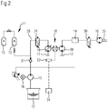
- Figur 2
- eine alternative Ausgestaltung der Erfindung mit einem mittels der Hydraulikpumpe der Motor-Pumpen-Einheit mit druckbeaufschlagtem Hydraulikmedium versorgten Verbraucher.
- In der
Figur 1 ist ein erfindungsgemäßes hydrostatisches System gezeigt, das zum Antreiben eines Verbrennungsmotors, insbesondere einer Pumpstation für eine Öl- oder Gas-Pipeline, genutzt wird. Die Erfindung ist jedoch nicht hierauf beschränkt. - In der
Figur 1 ist der Verbrennungsmotor mit 1 beziffert, die exemplarisch dargestellten Förderpumpen der Gas-Pipeline 4 mit 2 und 3. Die Darstellung der Pumpstation 5 ist sehr schematisch. - Das hydrostatische System zum Anfahren des Verbrennungsmotors 1 weist einen Hydraulikmotor 10 auf, der über eine Kupplung 6 mit dem Verbrennungsmotor 1 koppelbar ist. Zusätzlich oder anstelle der Kupplung 6 können auch eine oder mehrere Übersetzungsstufen und/oder wenigstens ein Getriebe vorgesehen sein.
- Der Hydraulikmotor 10 wird aus einer hydraulischen Druckquelle 11 gespeist. Die Druckquelle 11 umfasst im gezeigten Ausführungsbeispiel einen Druckspeicher 12, hier in Form eines Speichers mit Gasspannvorrichtung. Bevorzugt ist am Druckspeicher 12 ein weiterer gasgefüllter, insbesondere stickstoffgefüllter Gasspeicher 13 angeschlossen, der mit der Gasseite des Druckspeichers 12 in Verbindung steht beziehungsweise in eine solche strömungsleitende Verbindung schaltbar ist. Damit kann die Gasfeder des Druckspeichers vergrößert werden und der maximal mögliche Hydraulikmediumvorrat im Druckspeicher 12 steigt bei gleichbleibendem Druckniveau, insbesondere bei gleichbleibendem Vorspanndruck der Gasfeder und bei gleichbleibendem maximalen Speicherdruck. Der Gasspeicher 13 weist beispielsweise dasselbe Volumen wie der Druckspeicher 12 auf.
- In der
Figur 1 ist schematisch angedeutet, dass zusätzlich zu dem ersten Hydraulikmotor 10 wenigstens ein Verbraucher 14 im hydraulischen System vorgesehen sein könnte, der mit Hydraulikmedium aus der Druckquelle 11 gespeist wird. Bei einem solchen Verbraucher 14 handelt es sich beispielsweise um einen Arbeitszylinder, einen Hydraulikmotor, eine Pumpe oder dergleichen. Die Erfindung ist auch bei einem hydrostatischen System anwendbar, bei welchem nur ein entsprechender Verbraucher 14 ohne den ersten Hydraulikmotor 10 vorgesehen ist. - Die Druckquelle 11 kann mittels einer Ladepumpe 15 mit Hydraulikmedium aufgefüllt werden. Die Ladepumpe 15 wird beispielsweise von einem Elektromotor 16 angetrieben und fördert Hydraulikmedium aus dem Hydraulikvorrat 17.
- Zur Regelung des ersten Hydraulikmotors 10, insbesondere um den Verbrennungsmotor 1 mit minimalem Energieverbrauch aus der hydraulischen Druckquelle 11 zu starten, ist eine hydraulische Motor-Pumpen-Einheit 18 vorgesehen, die einen zusätzlichen Hydraulikmotor 19 und eine Hydraulikpumpe 20 aufweist, wobei die Hydraulikpumpe 20 vom zusätzlichen Hydraulikmotor 19 angetrieben wird.
- Der zusätzliche Hydraulikmotor 19 kann, wie schematisch angedeutet ist, als Konstantmotor oder als Verstellmotor ausgeführt sein. Entsprechend kann die Hydraulikpumpe 20 als Konstantpumpe oder Verstellpumpe ausgeführt sein. Die Hydraulikpumpe 20 kann in einem festen Drehzahlverhältnis insbesondere rein mechanisch am zusätzlichen Hydraulikmotor 19 angeschlossen sein, wobei sie insbesondere mit derselben Drehzahl umläuft. Alternativ kann in der Triebverbindung zwischen dem zusätzlichen Hydraulikmotor 19 und der Hydraulikpumpe 20 ein Übersetzungsgetriebe 21 mit variablem Drehzahlverhältnis vorgesehen sein.
- Der zusätzliche Hydraulikmotor 19 ist in Reihe zum dem ersten Hydraulikmotor 10 und/oder dem wenigstens einen Verbraucher 14 an der hydraulischen Druckquelle 11 angeschlossen.
- Durch Betreiben der Motor-Pumpen-Einheit 18 wird der von der hydraulischen Druckquelle 11 zur Verfügung gestellte Druck reduziert, sodass der erste Hydraulikmotor 10 eine entsprechend geringere Antriebsleistung an seiner Abtriebswelle 25, die den Leistungsausgang des hydrostatischen Systems bildet, zur Verfügung stellt. Zugleich wird durch Antreiben der Hydraulikpumpe 20 der Volumenstrom durch den ersten Hydraulikmotor 10 erhöht, sodass eine feinfühlige Regelung erzielt werden kann und dem hydrostatischen System nur in einem gewünschten geringen Ausmaß Energie entzogen werden kann.
- Bei Bedarf kann die hydraulische Motor-Pumpen-Einheit 18 einen elektrischen Generator oder einen Motorgenerator 22 aufweisen, um weitere Energie aus dem hydraulischen Kreislauf abzuführen, indem der elektrische Speicher 23 geladen wird. Bei Vorsehen eines Motorgenerators 22 kann diese Energie später dem System wieder zugeführt werden, durch Antrieb der Hydraulikpumpe 20 und/oder des zusätzlichen Hydraulikmotors 19.
- Wenn der zusätzliche Hydraulikmotor 19 als Pumpe betrieben werden kann, die in den Hydraulikvorrat 17 speist, so wird der Differenzdruck über dem ersten Hydraulikmotor 10 beziehungsweise dem wenigstens einen Verbraucher 14 erhöht. Ferner ist es möglich, dass in diesem Fall der zusätzliche Hydraulikmotor 19 einen erhöhten Druck für ein anderes Teilsystem oder einen anderen Verbraucher zur Verfügung stellt. Für diesen Antrieb des zusätzlichen Hydraulikmotors 19 kann der Motorgenerator 22 herangezogen werden und/oder die Hydraulikpumpe 20, wenn diese motorisch betreibbar ist.
- Falls die Regelungskapazität der Motor-Pumpen-Einheit 18 nicht ausreicht, um die gewünschte Antriebleistungsreduzierung des ersten Hydraulikmotors 10 in ausreichendem Maße zu gewährleisten und dadurch den Verbrauch von Hydraulikmedium aus der Druckquelle 11 zu minimieren, kann zusätzlich in der Druckleitung 26, die die Druckquelle 11 mit dem Verbraucher 14 und/oder dem ersten Hydraulikmotor 10 verbindet, ein einstellbares Drosselventil 24 vorgesehen sein, um den Hydraulikmediumstrom aus der Druckquelle 11 wahlweise mehr oder minder zu drosseln. Prinzipiell könnte ein solches Drosselventil 24 auch in Strömungsrichtung des Hydraulikmediums hinter dem Verbraucher 14 und/oder dem ersten Hydraulikmotor 10 vorgesehen sein, um den Druck stromabwärts anzustauen und dadurch die Druckdifferenz über dem Verbraucher 14 und/oder dem ersten Hydraulikmotor 10 zu reduzieren.
- In der
Figur 2 ist eine alternative Ausgestaltung der Erfindung gezeigt, wobei dieselben Bezugszeichen für sich entsprechende Bauteile verwendet werden. Bei der Ausgestaltung gemäß derFigur 2 wird der Druckspeicher 12 ebenfalls mittels der Ladepumpe 15 befüllt, hier jedoch über ein Rückschlagventil 31. Dies ist jedoch nicht zwingend. - Auch bei der Ausgestaltung gemäß der
Figur 2 ist eine hydraulische Motor-Pumpen-Einheit 18 vorgesehen, wobei der zusätzliche Hydraulikmotor 19 an der Druckleitung 26 und somit zu seinem Antrieb an der Druckquelle 11 angeschlossen ist. Zur Hydraulikmediumversorgung beziehungsweise Druckversorgung des Verbrauchers 14 wird hingegen die Hydraulikpumpe 20 der hydraulischen Motor-Pumpen-Einheit 18 verwendet. Die Hydraulikpumpe 20 fördert ebenfalls aus dem Hydraulikmediumvorrat 17 zu dem Verbraucher 14. Somit ist der Verbraucher 14 nicht in Reihe zu dem zusätzlichen Hydraulikmotor 19 an der Druckleitung 26 angeschlossen, sondern die Druckquelle 11 dient nur mittelbar zur druckbeaufschlagten Hydraulikmediumversorgung des Verbrauchers 14. Wie in derFigur 2 durch die gestrichelten Linien angedeutet ist, könnte anstelle des Verbrauchers 14 oder zusätzlich zu dem Verbraucher 14 auch hier wiederum ein erster Hydraulikmotor 10 vorgesehen sein, der mit Hydraulikmedium aus der Hydraulikpumpe 20 versorgt wird. Das Zu- und Abschalten des ersten Hydraulikmotors 10 kann beispielsweise über ein hier exemplarisch dargestelltes Ventil 30, insbesondere in Form eines Schaltventils oder Wegeventils, erfolgen. - Beispielsweise ist ein Sensor 33 vorgesehen, der zusammen mit einer Steuereinrichtung 34 die Drehzahl der hydraulischen Motor-Pumpen-Einheit 18 und damit indirekt den aktuellen Hydraulikmediumverbrauch des Verbrauchers 14 beziehungsweise die Drehzahl des ersten Hydraulikmotors 10 und/oder eines von diesem angetriebenen Aggregates bestimmt. Entsprechendes kann natürlich auch bei der Ausgestaltung gemäß der
Figur 1 angewendet werden. Bei der Ausgestaltung gemäß derFigur 2 könnte mittels des ersten Hydraulikmotors 10 ebenfalls analog zu der Ausgestaltung derFigur 1 oder einer ähnlichen Gestaltung ein Verbrennungsmotor angetrieben beziehungsweise beschleunigt werden, beispielsweise einer Pumpstation für eine Öl- oder Gas-Pipeline.
Claims (17)
- Hydrostatisches System1.1 mit einer hydraulischen Druckquelle (11);1.2 mit einem ersten Hydraulikmotor (10), der eine Abtriebswelle (25) aufweist, die einen mechanischen Leistungsausgang des hydrostatischen Systems bildet, und/oder mit wenigstens einem mit druckbeaufschlagtem Hydraulikmedium aus der Druckquelle (11) beaufschlagten Verbraucher (14), wobei1.3 der erste Hydraulikmotor (10) zu seinem Antrieb und/oder der wenigstens eine Verbraucher (14) zu seiner Druckbeaufschlagung mit einer Druckleitung (26) an der Druckquelle (11) angeschlossen ist; dadurch gekennzeichnet, dass1.4 eine hydraulische Motor-Pumpen-Einheit (18) vorgesehen ist, umfassend einen zusätzlichen Hydraulikmotor (19) und eine Hydraulikpumpe (20), die in einer Triebverbindung miteinander stehen, derart, dass die Hydraulikpumpe (20) vom zusätzlichen Hydraulikmotor (19) antreibbar ist, wobei1.5 der zusätzliche Hydraulikmotor (19) zu seinem Antrieb in Reihe zu dem ersten Hydraulikmotor (10) und/oder dem wenigstens einen Verbraucher (14) an der Druckquelle (11) angeschlossen ist und1.6 die Hydraulikpumpe (20) eine Druckseite aufweist, mit welcher sie an der Druckleitung (26) angeschlossen ist.
- Hydrostatisches System2.1 mit einer hydraulischen Druckquelle (11);2.2 mit wenigstens einem mit druckbeaufschlagtem Hydraulikmedium beaufschlagbaren ersten Hydraulikmotor (10) und/oder Verbraucher (14); dadurch gekennzeichnet, dass2.3 eine hydraulische Motor-Pumpen-Einheit (18) vorgesehen ist, umfassend einen zusätzlichen Hydraulikmotor (19) und eine Hydraulikpumpe (20), die in einer Triebverbindung miteinander stehen, derart, dass die Hydraulikpumpe (20) vom zusätzlichen Hydraulikmotor (19) antreibbar ist, wobei2.4 der zusätzliche Hydraulikmotor (19) zu seinem Antrieb mit einer Druckleitung (26) an der Druckquelle (11) angeschlossen ist, und2.5 der erste Hydraulikmotor (10) zu seinem Antrieb und/oder der Verbraucher (14) zu seiner Druckbeaufschlagung mit Hydraulikmedium an einer Druckseite der Hydraulikpumpe (20) angeschlossen ist.
- Hydrostatisches System gemäß einem der Ansprüche 1 oder 2, dadurch gekennzeichnet, dass ein Hydraulikvorrat (17), insbesondere in Form eines Hydrauliktanks oder Hydrauliksumpfes, vorgesehen ist, aus welchem die hydraulische Druckquelle (11) mittels wenigstens einer Ladepumpe (15) gespeist wird.
- Hydrostatisches System gemäß Anspruch 3, dadurch gekennzeichnet, dass die hydraulische Druckquelle (11) wenigstens einen Druckspeicher (12) umfasst, an welchem die Ladepumpe (15) mit einer Ladepumpendruckseite zur Speisung von Hydraulikmedium in den Druckspeicher (12) angeschlossen ist.
- Hydrostatisches System gemäß einem der Ansprüche 3 oder 4, dadurch gekennzeichnet, dass die hydraulische Druckquelle (11) wenigstens einen Druckspeicher (12) und einen am Druckspeicher (12) angeschlossenen Gasspeicher (13) umfasst, der mit einer Gasseite des Druckspeichers (12) in strömungsleitender Verbindung steht oder in eine solche Verbindung schaltbar ist.
- Hydrostatisches System gemäß einem der Ansprüche 3 bis 5, dadurch gekennzeichnet, dass die Hydraulikpumpe (20) eine Saugseite aufweist, die an dem Hydraulikvorrat (17) mittels einer Saugleitung angeschlossen ist.
- Hydrostatisches System gemäß einem der Ansprüche 4 bis 6, dadurch gekennzeichnet, dass die hydraulische Druckquelle (11) eine Vielzahl von Druckspeichern (12) umfasst.
- Hydrostatisches System gemäß einem der Ansprüche 1 bis 7, dadurch gekennzeichnet, dass in der Druckleitung (26) ein variabel einstellbares Drosselventil (24) zur Regelung des Druckes in der Druckleitung eingangsseitig oder ausgangsseitig des ersten Hydraulikmotors (10), des zusätzlichen Hydraulikmotors (19) und/oder wenigstens einen Verbrauchers (14) vorgesehen ist.
- Hydrostatisches System gemäß einem der Ansprüche 1 bis 8, dadurch gekennzeichnet, dass die Triebverbindung zwischen dem zusätzlichen Hydraulikmotor (19) und der Hydraulikpumpe (20) rein mechanisch ausgeführt ist.
- Hydrostatisches System gemäß einem der Ansprüche 1 bis 9, dadurch gekennzeichnet, dass die Triebverbindung zwischen dem zusätzlichen Hydraulikmotor (19) und der Hydraulikpumpe (20) durch eine starre Kopplung hergestellt ist, insbesondere mit einer Welle, die Laufräder des zusätzlichen Hydraulikmotors (19) und der Hydraulikpumpe (20) trägt und/oder drehstarr an diesen angeschlossen ist.
- Hydrostatisches System gemäß einem der Ansprüche 1 bis 10, dadurch gekennzeichnet, dass der zusätzliche Hydraulikmotor (19) als Verstellmotor und/oder die Hydraulikpumpe (20) als Verstellpumpe mit variabel einstellbarem Fördervolumen pro Umdrehung, insbesondere variabel einstellbarem Hubvolumen, ausgeführt ist/sind.
- Hydrostatisches System gemäß einem der Ansprüche 1 bis 9, dadurch gekennzeichnet, dass in der Triebverbindung zwischen dem zusätzlichen Hydraulikmotor (19) und der Hydraulikpumpe (20) ein Übersetzungsgetriebe (21) mit variablem Drehzahlverhältnis vorgesehen ist.
- Hydrostatisches System gemäß einem der Ansprüche 1 bis 12, dadurch gekennzeichnet, dass an der hydraulischen Motor-Pumpen-Einheit (18) ein elektrischer Generator oder elektrischer Motorgenerator (22) zur Energiespeicherung, reversiblen Energiespeicherung und/oder Bereitstellung elektrischer Energie angeschlossen ist.
- Hydrostatisches System gemäß einem der Ansprüche 1 bis 13, dadurch gekennzeichnet, dass der zusätzliche Hydraulikmotor (19) als Hydraulikpumpe mit oder ohne Strömungsrichtungsumkehr des Hydraulikmediums betreibbar ist.
- Hydrostatisches System gemäß einem der Ansprüche 1 bis 14, dadurch gekennzeichnet, dass die Hydraulikpumpe (20) motorisch betreibbar ist.
- Hydrostatisches System gemäß einem der Ansprüche 3 bis 15, dadurch gekennzeichnet, dass der zusätzliche Hydraulikmotor (19) am Hydraulikvorrat (17) angeschlossen ist, um Hydraulikmedium aus der Druckleitung (26) in diesen zu fördern.
- Pumpstation (5) für eine Öl- oder Gas-Pipeline (4)17.1 mit wenigstens einer Förderpumpe (2, 3), um das Öl oder Gas durch die Pipeline (4) zu fördern;17.2 mit wenigstens einem Verbrennungsmotor (1) zum Antrieb der wenigstens einen Förderpumpe (2, 3);
dadurch gekennzeichnet, dass17.3 der Verbrennungsmotor (1) an einem hydrostatischen System gemäß einem der Ansprüche 1 bis 16 angeschlossen ist, wobei der Verbrennungsmotor (1) zu seinem Anfahren in einer Triebverbindung mit dem ersten Hydraulikmotor (10) steht oder in eine solche schaltbar ist, oder der Verbrennungsmotor (1) als Verbraucher (14) mit druckbeaufschlagtem Hydraulikmedium aus der Hydraulikpumpe (20) beaufschlagt wird.
Applications Claiming Priority (4)
| Application Number | Priority Date | Filing Date | Title |
|---|---|---|---|
| DE102016215758 | 2016-08-23 | ||
| DE102016217061.9A DE102016217061A1 (de) | 2016-08-23 | 2016-09-08 | Hydrostatisches System und Pumpstation für eine Öl- oder Gas-Pipeline |
| DE102016217959.4A DE102016217959A1 (de) | 2016-08-23 | 2016-09-20 | Pumpstation für eine Pipeline und Verfahren zum Starten eines Verbrennungsmotors in einer Pumpstation |
| PCT/EP2017/068616 WO2018036731A1 (de) | 2016-08-23 | 2017-07-24 | Hydrostatisches system und pumpstation für eine öl- oder gas-pipeline |
Publications (2)
| Publication Number | Publication Date |
|---|---|
| EP3504435A1 EP3504435A1 (de) | 2019-07-03 |
| EP3504435B1 true EP3504435B1 (de) | 2020-04-01 |
Family
ID=61167147
Family Applications (2)
| Application Number | Title | Priority Date | Filing Date |
|---|---|---|---|
| EP17745164.8A Active EP3504435B1 (de) | 2016-08-23 | 2017-07-24 | Hydrostatisches system und pumpstation für eine öl- oder gas-pipeline |
| EP17745163.0A Active EP3504434B1 (de) | 2016-08-23 | 2017-07-24 | Pumpstation für eine pipeline und verfahren zum starten eines verbrennungsmotors in einer pumpstation |
Family Applications After (1)
| Application Number | Title | Priority Date | Filing Date |
|---|---|---|---|
| EP17745163.0A Active EP3504434B1 (de) | 2016-08-23 | 2017-07-24 | Pumpstation für eine pipeline und verfahren zum starten eines verbrennungsmotors in einer pumpstation |
Country Status (5)
| Country | Link |
|---|---|
| US (2) | US11111908B2 (de) |
| EP (2) | EP3504435B1 (de) |
| DE (2) | DE102016217061A1 (de) |
| WO (2) | WO2018036731A1 (de) |
| ZA (2) | ZA201900107B (de) |
Cited By (1)
| Publication number | Priority date | Publication date | Assignee | Title |
|---|---|---|---|---|
| DE102023205226A1 (de) | 2023-06-05 | 2024-12-05 | Robert Bosch Gesellschaft mit beschränkter Haftung | Verfahren zum Betreiben eines hydraulischen Antriebs und hydraulischer Antrieb |
Families Citing this family (5)
| Publication number | Priority date | Publication date | Assignee | Title |
|---|---|---|---|---|
| JP6713438B2 (ja) * | 2017-08-25 | 2020-06-24 | 三菱重工業株式会社 | 油圧ドライブトレイン及びその起動方法、並びに発電装置及びその起動方法 |
| FR3109611B1 (fr) * | 2020-04-28 | 2022-08-12 | Ortec Expansion | Dispositif d’entraînement d’une pompe à très haute pression comprenant un système de régulation hydraulique précis et sécurisé. |
| US12173844B2 (en) | 2021-03-26 | 2024-12-24 | Circor Pumps North America, Llc | High efficiency seal oil system |
| CN113417903A (zh) | 2021-07-28 | 2021-09-21 | 安百拓(南京)建筑矿山设备有限公司 | 一种动力系统和行走动力站 |
| CN113969854B (zh) * | 2021-10-25 | 2023-03-24 | 中国煤炭科工集团太原研究院有限公司 | 一种矿用防爆车辆气电联合控制启动系统 |
Family Cites Families (22)
| Publication number | Priority date | Publication date | Assignee | Title |
|---|---|---|---|---|
| GB808745A (en) * | 1955-08-03 | 1959-02-11 | Caterpillar Tractor Co | Remote control for pipeline pumping engines |
| DE2340386A1 (de) * | 1973-08-09 | 1975-02-20 | Normar Eng Co Ltd | Vorrichtung zum betaetigen eines hydraulikmotors |
| RU2035614C1 (ru) | 1992-09-07 | 1995-05-20 | Индивидуальное частное предприятие "Единство" Х.Халикова | Система запуска дизельного двигателя внутреннего сгорания |
| US5507144A (en) * | 1995-04-27 | 1996-04-16 | The United States Of America As Represented By The Administrator Of The U.S. Environmental Protection Agency | Lightweight, safe hydraulic power system and a method of operation thereof |
| US5660198A (en) | 1995-12-21 | 1997-08-26 | J. C. Carter Company, Inc. | Flow compensated pressure control system |
| AT3753U1 (de) | 1999-06-24 | 2000-07-25 | Avl List Gmbh | Brennkraftmaschine, insbesondere mit selbstzündung |
| US6615786B2 (en) | 2001-05-11 | 2003-09-09 | Honda Giken Kogyo Kabushiki Kaisha | Starter system for internal combustion engine |
| JP2002339841A (ja) * | 2001-05-15 | 2002-11-27 | Honda Motor Co Ltd | 車両の油圧式エンジン始動装置 |
| US20050196298A1 (en) * | 2004-03-05 | 2005-09-08 | Manning John B. | Gas compressor dual drive mechanism |
| DE202006009223U1 (de) * | 2006-05-17 | 2007-09-27 | Liebherr-Werk Bischofshofen Ges.M.B.H. | Maschine, insbesondere Baumaschine |
| DE102006026829A1 (de) * | 2006-06-07 | 2007-12-13 | Schiefer, Heinz, Dipl.-Ing. | System zum Leiten von Gefahrstoffen |
| DE102006058003A1 (de) * | 2006-12-08 | 2008-06-19 | Robert Bosch Gmbh | Verfahren zur Steuerung eines Antriebs und Antriebssystem |
| DE202008008045U1 (de) | 2008-06-16 | 2009-11-05 | Liebherr-Hydraulikbagger Gmbh | Hydraulischer Antrieb |
| US20100077998A1 (en) | 2008-10-01 | 2010-04-01 | Kansas State University Research Foundation | Turbocharger booster system |
| RU2444649C1 (ru) * | 2010-07-13 | 2012-03-10 | Александр Анатольевич Строганов | Устройство для рекуперации гидравлической энергии |
| ES1072269Y (es) | 2010-03-29 | 2010-09-13 | Gimeno Manuel Carcare | Arrancador oleohidraulico para motor de combustion interna |
| DE102011105006A1 (de) | 2011-04-04 | 2012-10-04 | Linde Material Handling Gmbh | Antriebsstrang eines Fahrzeugs |
| DE102012108857B4 (de) * | 2012-09-20 | 2022-01-13 | Linde Hydraulics Gmbh & Co. Kg | Hydrostatische Startereinrichtung eines Verbrennungsmotors |
| DE102012021327A1 (de) * | 2012-10-26 | 2014-01-23 | Voith Patent Gmbh | Förderanlage für Öl oder Gas |
| DE102013110239A1 (de) * | 2013-08-22 | 2015-02-26 | Linde Hydraulics Gmbh & Co. Kg | Hydrostatisches Triebwerk |
| DE102013227035A1 (de) | 2013-12-20 | 2015-06-25 | Hamm Ag | Antriebssystem, insbesondere für eine selbstfahrende Baumaschine, insbesondere Bodenverdichter |
| DE102014215567A1 (de) | 2014-08-06 | 2016-02-11 | Robert Bosch Gmbh | Hydrostatischer Antrieb |
-
2016
- 2016-09-08 DE DE102016217061.9A patent/DE102016217061A1/de not_active Withdrawn
- 2016-09-20 DE DE102016217959.4A patent/DE102016217959A1/de not_active Withdrawn
-
2017
- 2017-07-24 EP EP17745164.8A patent/EP3504435B1/de active Active
- 2017-07-24 US US16/327,456 patent/US11111908B2/en not_active Expired - Fee Related
- 2017-07-24 EP EP17745163.0A patent/EP3504434B1/de active Active
- 2017-07-24 WO PCT/EP2017/068616 patent/WO2018036731A1/de not_active Ceased
- 2017-07-24 WO PCT/EP2017/068610 patent/WO2018036730A1/de not_active Ceased
- 2017-07-24 US US16/327,941 patent/US10935012B2/en not_active Expired - Fee Related
-
2019
- 2019-01-08 ZA ZA2019/00107A patent/ZA201900107B/en unknown
- 2019-01-10 ZA ZA2019/00168A patent/ZA201900168B/en unknown
Non-Patent Citations (1)
| Title |
|---|
| None * |
Cited By (1)
| Publication number | Priority date | Publication date | Assignee | Title |
|---|---|---|---|---|
| DE102023205226A1 (de) | 2023-06-05 | 2024-12-05 | Robert Bosch Gesellschaft mit beschränkter Haftung | Verfahren zum Betreiben eines hydraulischen Antriebs und hydraulischer Antrieb |
Also Published As
| Publication number | Publication date |
|---|---|
| US20190195210A1 (en) | 2019-06-27 |
| US10935012B2 (en) | 2021-03-02 |
| ZA201900107B (en) | 2019-08-28 |
| EP3504434A1 (de) | 2019-07-03 |
| US20190186477A1 (en) | 2019-06-20 |
| WO2018036731A1 (de) | 2018-03-01 |
| WO2018036730A1 (de) | 2018-03-01 |
| US11111908B2 (en) | 2021-09-07 |
| EP3504435A1 (de) | 2019-07-03 |
| EP3504434B1 (de) | 2020-07-08 |
| DE102016217959A1 (de) | 2018-03-01 |
| DE102016217061A1 (de) | 2018-03-01 |
| ZA201900168B (en) | 2019-09-25 |
Similar Documents
| Publication | Publication Date | Title |
|---|---|---|
| EP2503160B1 (de) | Hydraulisches Antriebssystem | |
| WO2018036731A1 (de) | Hydrostatisches system und pumpstation für eine öl- oder gas-pipeline | |
| EP2267317B1 (de) | Hydrauliksystem | |
| EP2834542B1 (de) | Geschlossener hydraulischer kreislauf | |
| EP2890904B1 (de) | Hydraulisches energierückgewinnungssystem | |
| EP2694803B1 (de) | Hydraulisch elektrischer wandler, wandleranordnung und verfahren zum ansteuern eines wandlers | |
| DE202007014676U1 (de) | Hydraulisches Antriebssystem | |
| EP1828617A1 (de) | Hydraulischer antrieb | |
| DE102014221594A1 (de) | Hydrostatisches Bremskonzept | |
| DE102013205807A1 (de) | Rudermaschine | |
| DE102009021866A1 (de) | Hydroantrieb mit einer unabhängigen Speisepumpe | |
| DE102008057897A1 (de) | Hydrostatischer Antrieb und Verfahren zum Betreiben eines Fahrzeugs | |
| DE102016011900A1 (de) | Hydraulische Antriebsvorrichtung für eine Formgebungsmaschine | |
| DE102010020690B4 (de) | Hydraulisches Antriebssystem | |
| EP3580837B1 (de) | Antriebseinrichtung zur energieversorgung hochbelasteter elektromotoren | |
| EP2046623B1 (de) | System mit einem verdichter und einem verbraucher in einem kraftfahrzeug | |
| EP2191996B1 (de) | Mobile Arbeitsmaschine, insbesondere Flurförderzeug, und Verfahren zum Betreiben der mobilen Arbeitsmaschine | |
| DE102010054045A1 (de) | Antriebssystem mit einem Antriebsmotor und einem Schaltgetriebe und einer Vorrichtung zur Energierückgewinnung | |
| DE102010028030A1 (de) | Antriebsanordnung und Verfahren zum Durchführen eines Anfahrvorganges | |
| EP3517689A1 (de) | Hydraulischer rüttlerantrieb sowie ein ramm- und/oder bohrgerät mit einem hydraulischen rüttlerantrieb | |
| DE102008047991A1 (de) | Antriebsstrang in einem Fahrzeug | |
| DE102005061165A1 (de) | Antrieb für ein Nebenaggregat oder Hilfsaggregat eines Kraftfahrzeugs | |
| EP2024666A1 (de) | Hydrostatischer antrieb mit einem offenen hydraulischen kreislauf und einem geschlossenen hydraullischen kreislauf |
Legal Events
| Date | Code | Title | Description |
|---|---|---|---|
| STAA | Information on the status of an ep patent application or granted ep patent |
Free format text: STATUS: UNKNOWN |
|
| STAA | Information on the status of an ep patent application or granted ep patent |
Free format text: STATUS: THE INTERNATIONAL PUBLICATION HAS BEEN MADE |
|
| PUAI | Public reference made under article 153(3) epc to a published international application that has entered the european phase |
Free format text: ORIGINAL CODE: 0009012 |
|
| STAA | Information on the status of an ep patent application or granted ep patent |
Free format text: STATUS: REQUEST FOR EXAMINATION WAS MADE |
|
| 17P | Request for examination filed |
Effective date: 20190325 |
|
| AK | Designated contracting states |
Kind code of ref document: A1 Designated state(s): AL AT BE BG CH CY CZ DE DK EE ES FI FR GB GR HR HU IE IS IT LI LT LU LV MC MK MT NL NO PL PT RO RS SE SI SK SM TR |
|
| AX | Request for extension of the european patent |
Extension state: BA ME |
|
| DAV | Request for validation of the european patent (deleted) | ||
| DAX | Request for extension of the european patent (deleted) | ||
| RAP1 | Party data changed (applicant data changed or rights of an application transferred) |
Owner name: VOITH PATENT GMBH |
|
| GRAP | Despatch of communication of intention to grant a patent |
Free format text: ORIGINAL CODE: EPIDOSNIGR1 |
|
| STAA | Information on the status of an ep patent application or granted ep patent |
Free format text: STATUS: GRANT OF PATENT IS INTENDED |
|
| INTG | Intention to grant announced |
Effective date: 20191217 |
|
| GRAS | Grant fee paid |
Free format text: ORIGINAL CODE: EPIDOSNIGR3 |
|
| GRAA | (expected) grant |
Free format text: ORIGINAL CODE: 0009210 |
|
| STAA | Information on the status of an ep patent application or granted ep patent |
Free format text: STATUS: THE PATENT HAS BEEN GRANTED |
|
| AK | Designated contracting states |
Kind code of ref document: B1 Designated state(s): AL AT BE BG CH CY CZ DE DK EE ES FI FR GB GR HR HU IE IS IT LI LT LU LV MC MK MT NL NO PL PT RO RS SE SI SK SM TR |
|
| REG | Reference to a national code |
Ref country code: GB Ref legal event code: FG4D Free format text: NOT ENGLISH |
|
| REG | Reference to a national code |
Ref country code: CH Ref legal event code: EP Ref country code: AT Ref legal event code: REF Ref document number: 1251673 Country of ref document: AT Kind code of ref document: T Effective date: 20200415 |
|
| REG | Reference to a national code |
Ref country code: DE Ref legal event code: R096 Ref document number: 502017004547 Country of ref document: DE |
|
| REG | Reference to a national code |
Ref country code: IE Ref legal event code: FG4D Free format text: LANGUAGE OF EP DOCUMENT: GERMAN |
|
| PG25 | Lapsed in a contracting state [announced via postgrant information from national office to epo] |
Ref country code: BG Free format text: LAPSE BECAUSE OF FAILURE TO SUBMIT A TRANSLATION OF THE DESCRIPTION OR TO PAY THE FEE WITHIN THE PRESCRIBED TIME-LIMIT Effective date: 20200701 |
|
| REG | Reference to a national code |
Ref country code: NL Ref legal event code: MP Effective date: 20200401 |
|
| REG | Reference to a national code |
Ref country code: LT Ref legal event code: MG4D |
|
| PG25 | Lapsed in a contracting state [announced via postgrant information from national office to epo] |
Ref country code: PT Free format text: LAPSE BECAUSE OF FAILURE TO SUBMIT A TRANSLATION OF THE DESCRIPTION OR TO PAY THE FEE WITHIN THE PRESCRIBED TIME-LIMIT Effective date: 20200817 Ref country code: GR Free format text: LAPSE BECAUSE OF FAILURE TO SUBMIT A TRANSLATION OF THE DESCRIPTION OR TO PAY THE FEE WITHIN THE PRESCRIBED TIME-LIMIT Effective date: 20200702 Ref country code: NO Free format text: LAPSE BECAUSE OF FAILURE TO SUBMIT A TRANSLATION OF THE DESCRIPTION OR TO PAY THE FEE WITHIN THE PRESCRIBED TIME-LIMIT Effective date: 20200701 Ref country code: NL Free format text: LAPSE BECAUSE OF FAILURE TO SUBMIT A TRANSLATION OF THE DESCRIPTION OR TO PAY THE FEE WITHIN THE PRESCRIBED TIME-LIMIT Effective date: 20200401 Ref country code: CZ Free format text: LAPSE BECAUSE OF FAILURE TO SUBMIT A TRANSLATION OF THE DESCRIPTION OR TO PAY THE FEE WITHIN THE PRESCRIBED TIME-LIMIT Effective date: 20200401 Ref country code: LT Free format text: LAPSE BECAUSE OF FAILURE TO SUBMIT A TRANSLATION OF THE DESCRIPTION OR TO PAY THE FEE WITHIN THE PRESCRIBED TIME-LIMIT Effective date: 20200401 Ref country code: SE Free format text: LAPSE BECAUSE OF FAILURE TO SUBMIT A TRANSLATION OF THE DESCRIPTION OR TO PAY THE FEE WITHIN THE PRESCRIBED TIME-LIMIT Effective date: 20200401 Ref country code: IS Free format text: LAPSE BECAUSE OF FAILURE TO SUBMIT A TRANSLATION OF THE DESCRIPTION OR TO PAY THE FEE WITHIN THE PRESCRIBED TIME-LIMIT Effective date: 20200801 Ref country code: FI Free format text: LAPSE BECAUSE OF FAILURE TO SUBMIT A TRANSLATION OF THE DESCRIPTION OR TO PAY THE FEE WITHIN THE PRESCRIBED TIME-LIMIT Effective date: 20200401 |
|
| PG25 | Lapsed in a contracting state [announced via postgrant information from national office to epo] |
Ref country code: HR Free format text: LAPSE BECAUSE OF FAILURE TO SUBMIT A TRANSLATION OF THE DESCRIPTION OR TO PAY THE FEE WITHIN THE PRESCRIBED TIME-LIMIT Effective date: 20200401 Ref country code: LV Free format text: LAPSE BECAUSE OF FAILURE TO SUBMIT A TRANSLATION OF THE DESCRIPTION OR TO PAY THE FEE WITHIN THE PRESCRIBED TIME-LIMIT Effective date: 20200401 Ref country code: RS Free format text: LAPSE BECAUSE OF FAILURE TO SUBMIT A TRANSLATION OF THE DESCRIPTION OR TO PAY THE FEE WITHIN THE PRESCRIBED TIME-LIMIT Effective date: 20200401 |
|
| PG25 | Lapsed in a contracting state [announced via postgrant information from national office to epo] |
Ref country code: AL Free format text: LAPSE BECAUSE OF FAILURE TO SUBMIT A TRANSLATION OF THE DESCRIPTION OR TO PAY THE FEE WITHIN THE PRESCRIBED TIME-LIMIT Effective date: 20200401 |
|
| REG | Reference to a national code |
Ref country code: DE Ref legal event code: R097 Ref document number: 502017004547 Country of ref document: DE |
|
| PG25 | Lapsed in a contracting state [announced via postgrant information from national office to epo] |
Ref country code: RO Free format text: LAPSE BECAUSE OF FAILURE TO SUBMIT A TRANSLATION OF THE DESCRIPTION OR TO PAY THE FEE WITHIN THE PRESCRIBED TIME-LIMIT Effective date: 20200401 Ref country code: ES Free format text: LAPSE BECAUSE OF FAILURE TO SUBMIT A TRANSLATION OF THE DESCRIPTION OR TO PAY THE FEE WITHIN THE PRESCRIBED TIME-LIMIT Effective date: 20200401 Ref country code: SM Free format text: LAPSE BECAUSE OF FAILURE TO SUBMIT A TRANSLATION OF THE DESCRIPTION OR TO PAY THE FEE WITHIN THE PRESCRIBED TIME-LIMIT Effective date: 20200401 Ref country code: EE Free format text: LAPSE BECAUSE OF FAILURE TO SUBMIT A TRANSLATION OF THE DESCRIPTION OR TO PAY THE FEE WITHIN THE PRESCRIBED TIME-LIMIT Effective date: 20200401 Ref country code: IT Free format text: LAPSE BECAUSE OF FAILURE TO SUBMIT A TRANSLATION OF THE DESCRIPTION OR TO PAY THE FEE WITHIN THE PRESCRIBED TIME-LIMIT Effective date: 20200401 Ref country code: DK Free format text: LAPSE BECAUSE OF FAILURE TO SUBMIT A TRANSLATION OF THE DESCRIPTION OR TO PAY THE FEE WITHIN THE PRESCRIBED TIME-LIMIT Effective date: 20200401 |
|
| PLBE | No opposition filed within time limit |
Free format text: ORIGINAL CODE: 0009261 |
|
| STAA | Information on the status of an ep patent application or granted ep patent |
Free format text: STATUS: NO OPPOSITION FILED WITHIN TIME LIMIT |
|
| PG25 | Lapsed in a contracting state [announced via postgrant information from national office to epo] |
Ref country code: PL Free format text: LAPSE BECAUSE OF FAILURE TO SUBMIT A TRANSLATION OF THE DESCRIPTION OR TO PAY THE FEE WITHIN THE PRESCRIBED TIME-LIMIT Effective date: 20200401 Ref country code: MC Free format text: LAPSE BECAUSE OF FAILURE TO SUBMIT A TRANSLATION OF THE DESCRIPTION OR TO PAY THE FEE WITHIN THE PRESCRIBED TIME-LIMIT Effective date: 20200401 Ref country code: SK Free format text: LAPSE BECAUSE OF FAILURE TO SUBMIT A TRANSLATION OF THE DESCRIPTION OR TO PAY THE FEE WITHIN THE PRESCRIBED TIME-LIMIT Effective date: 20200401 |
|
| REG | Reference to a national code |
Ref country code: CH Ref legal event code: PL |
|
| 26N | No opposition filed |
Effective date: 20210112 |
|
| REG | Reference to a national code |
Ref country code: BE Ref legal event code: MM Effective date: 20200731 |
|
| PG25 | Lapsed in a contracting state [announced via postgrant information from national office to epo] |
Ref country code: CH Free format text: LAPSE BECAUSE OF NON-PAYMENT OF DUE FEES Effective date: 20200731 Ref country code: LU Free format text: LAPSE BECAUSE OF NON-PAYMENT OF DUE FEES Effective date: 20200724 Ref country code: LI Free format text: LAPSE BECAUSE OF NON-PAYMENT OF DUE FEES Effective date: 20200731 Ref country code: FR Free format text: LAPSE BECAUSE OF NON-PAYMENT OF DUE FEES Effective date: 20200731 |
|
| PG25 | Lapsed in a contracting state [announced via postgrant information from national office to epo] |
Ref country code: BE Free format text: LAPSE BECAUSE OF NON-PAYMENT OF DUE FEES Effective date: 20200731 Ref country code: SI Free format text: LAPSE BECAUSE OF FAILURE TO SUBMIT A TRANSLATION OF THE DESCRIPTION OR TO PAY THE FEE WITHIN THE PRESCRIBED TIME-LIMIT Effective date: 20200401 |
|
| PG25 | Lapsed in a contracting state [announced via postgrant information from national office to epo] |
Ref country code: IE Free format text: LAPSE BECAUSE OF NON-PAYMENT OF DUE FEES Effective date: 20200724 |
|
| GBPC | Gb: european patent ceased through non-payment of renewal fee |
Effective date: 20210724 |
|
| PG25 | Lapsed in a contracting state [announced via postgrant information from national office to epo] |
Ref country code: GB Free format text: LAPSE BECAUSE OF NON-PAYMENT OF DUE FEES Effective date: 20210724 |
|
| PG25 | Lapsed in a contracting state [announced via postgrant information from national office to epo] |
Ref country code: TR Free format text: LAPSE BECAUSE OF FAILURE TO SUBMIT A TRANSLATION OF THE DESCRIPTION OR TO PAY THE FEE WITHIN THE PRESCRIBED TIME-LIMIT Effective date: 20200401 Ref country code: MT Free format text: LAPSE BECAUSE OF FAILURE TO SUBMIT A TRANSLATION OF THE DESCRIPTION OR TO PAY THE FEE WITHIN THE PRESCRIBED TIME-LIMIT Effective date: 20200401 Ref country code: CY Free format text: LAPSE BECAUSE OF FAILURE TO SUBMIT A TRANSLATION OF THE DESCRIPTION OR TO PAY THE FEE WITHIN THE PRESCRIBED TIME-LIMIT Effective date: 20200401 |
|
| PG25 | Lapsed in a contracting state [announced via postgrant information from national office to epo] |
Ref country code: MK Free format text: LAPSE BECAUSE OF FAILURE TO SUBMIT A TRANSLATION OF THE DESCRIPTION OR TO PAY THE FEE WITHIN THE PRESCRIBED TIME-LIMIT Effective date: 20200401 |
|
| PGFP | Annual fee paid to national office [announced via postgrant information from national office to epo] |
Ref country code: AT Payment date: 20230720 Year of fee payment: 7 |
|
| PGFP | Annual fee paid to national office [announced via postgrant information from national office to epo] |
Ref country code: DE Payment date: 20230719 Year of fee payment: 7 |
|
| REG | Reference to a national code |
Ref country code: DE Ref legal event code: R119 Ref document number: 502017004547 Country of ref document: DE |
|
| REG | Reference to a national code |
Ref country code: AT Ref legal event code: MM01 Ref document number: 1251673 Country of ref document: AT Kind code of ref document: T Effective date: 20240724 |
|
| PG25 | Lapsed in a contracting state [announced via postgrant information from national office to epo] |
Ref country code: DE Free format text: LAPSE BECAUSE OF NON-PAYMENT OF DUE FEES Effective date: 20250201 |
|
| PG25 | Lapsed in a contracting state [announced via postgrant information from national office to epo] |
Ref country code: AT Free format text: LAPSE BECAUSE OF NON-PAYMENT OF DUE FEES Effective date: 20240724 |