EP3504382B2 - Befestigungsprofil mit luftdurchlass und eine abgehängte deckenanordnung mit einem solchen profil - Google Patents
Befestigungsprofil mit luftdurchlass und eine abgehängte deckenanordnung mit einem solchen profil Download PDFInfo
- Publication number
- EP3504382B2 EP3504382B2 EP17768172.3A EP17768172A EP3504382B2 EP 3504382 B2 EP3504382 B2 EP 3504382B2 EP 17768172 A EP17768172 A EP 17768172A EP 3504382 B2 EP3504382 B2 EP 3504382B2
- Authority
- EP
- European Patent Office
- Prior art keywords
- profile
- air
- room
- hanger
- plenum
- Prior art date
- Legal status (The legal status is an assumption and is not a legal conclusion. Google has not performed a legal analysis and makes no representation as to the accuracy of the status listed.)
- Active
Links
Images


Classifications
-
- E—FIXED CONSTRUCTIONS
- E04—BUILDING
- E04B—GENERAL BUILDING CONSTRUCTIONS; WALLS, e.g. PARTITIONS; ROOFS; FLOORS; CEILINGS; INSULATION OR OTHER PROTECTION OF BUILDINGS
- E04B9/00—Ceilings; Construction of ceilings, e.g. false ceilings; Ceiling construction with regard to insulation
- E04B9/02—Ceilings; Construction of ceilings, e.g. false ceilings; Ceiling construction with regard to insulation having means for ventilation or vapour discharge
-
- E—FIXED CONSTRUCTIONS
- E04—BUILDING
- E04B—GENERAL BUILDING CONSTRUCTIONS; WALLS, e.g. PARTITIONS; ROOFS; FLOORS; CEILINGS; INSULATION OR OTHER PROTECTION OF BUILDINGS
- E04B9/00—Ceilings; Construction of ceilings, e.g. false ceilings; Ceiling construction with regard to insulation
- E04B9/30—Ceilings; Construction of ceilings, e.g. false ceilings; Ceiling construction with regard to insulation characterised by edge details of the ceiling; e.g. securing to an adjacent wall
- E04B9/303—Ceilings; Construction of ceilings, e.g. false ceilings; Ceiling construction with regard to insulation characterised by edge details of the ceiling; e.g. securing to an adjacent wall for flexible tensioned membranes
-
- F—MECHANICAL ENGINEERING; LIGHTING; HEATING; WEAPONS; BLASTING
- F24—HEATING; RANGES; VENTILATING
- F24F—AIR-CONDITIONING; AIR-HUMIDIFICATION; VENTILATION; USE OF AIR CURRENTS FOR SCREENING
- F24F7/00—Ventilation
- F24F7/04—Ventilation with ducting systems, e.g. by double walls; with natural circulation
-
- E—FIXED CONSTRUCTIONS
- E04—BUILDING
- E04B—GENERAL BUILDING CONSTRUCTIONS; WALLS, e.g. PARTITIONS; ROOFS; FLOORS; CEILINGS; INSULATION OR OTHER PROTECTION OF BUILDINGS
- E04B9/00—Ceilings; Construction of ceilings, e.g. false ceilings; Ceiling construction with regard to insulation
- E04B9/02—Ceilings; Construction of ceilings, e.g. false ceilings; Ceiling construction with regard to insulation having means for ventilation or vapour discharge
- E04B2009/026—Ceilings; Construction of ceilings, e.g. false ceilings; Ceiling construction with regard to insulation having means for ventilation or vapour discharge the supporting ceiling grid acting as air diffusers
-
- E—FIXED CONSTRUCTIONS
- E04—BUILDING
- E04B—GENERAL BUILDING CONSTRUCTIONS; WALLS, e.g. PARTITIONS; ROOFS; FLOORS; CEILINGS; INSULATION OR OTHER PROTECTION OF BUILDINGS
- E04B9/00—Ceilings; Construction of ceilings, e.g. false ceilings; Ceiling construction with regard to insulation
- E04B9/04—Ceilings; Construction of ceilings, e.g. false ceilings; Ceiling construction with regard to insulation comprising slabs, panels, sheets or the like
- E04B2009/0492—Ceilings; Construction of ceilings, e.g. false ceilings; Ceiling construction with regard to insulation comprising slabs, panels, sheets or the like with fabrics tensioned on frames
Definitions
- the invention relates to the field of false ceilings, and in particular that of stretch ceilings.
- the air circulated can come from a ventilation and/or air conditioning system (heating, cooling, dehumidification, humidification).
- False ceiling designs are known that allow air to pass into the room to be treated.
- a false ceiling fixing system is known that allows the false ceiling hanging profiles to be spaced apart by means of brackets or spacers fixed at regular intervals and thus generating a peripheral space.
- the patent application may be cited FR2815112 , and also the document FR 2 597 906 .
- the invention aims to remedy these problems by proposing a hanging profile allowing simple and rapid assembly of a ceiling assembly allowing the circulation of new and/or treated air within a room.
- the invention also aims to propose a ceiling assembly allowing precise control of air diffusion around the periphery of the room.
- the invention also aims to propose a ceiling assembly making it possible to avoid any visible device, and in particular grilles, while ensuring the circulation of air within the room concerned, whether this is circulation linked to the air conditioning or ventilation of the room concerned.
- the invention proposes a profile for hanging a canvas for producing a stretched ceiling in a room to be treated, as defined by claim 1.
- the hanging profile comprising at least two wings connected to each other by a connecting wall which extends horizontally between the room and a plenum, one of the wings being arranged to allow the hanging profile to be fixed to a wall of the room to be treated, a second wing, which constitutes a wing for hanging the canvas, being provided with a blocking end for a harpoon of a canvas, the connecting wall and the wing for hanging the canvas being arranged to together define an unobstructed slot for the passage of air through the profile and delimited by the blocking end of the harpoon of the wing for hanging the canvas, the profile comprising at least one passage opening arranged to allow the passage of air through said profile from or towards the slot, characterized in that the passage opening is provided on the connecting wall, said attachment profile defining, along the entire length of the wall, an open slot for the passage of air between
- the air passage slot is delimited by the wall or by the fixing wing of the profile.
- the configuration of the profile according to the invention thus makes it possible to define, along the entire wall, an open slot for the passage of air between the plenum and the room, devoid of any element blocking or hindering the passage of air, unlike the aforementioned prior arts.
- the openings provided on the connecting wall of the profile according to the invention which can each represent an open surface of several square centimeters (for example 4 cm 2 ) while being spaced less than 1 cm from each other, can form, for one meter of profile according to the invention, a cumulative open surface of several hundred square centimeters, thus offering a possibility of maximized air circulation.
- openings are provided on the profile according to the invention, on the connecting wall which extends horizontally between the room and the plenum, which facilitates the circulation of air between the room and the plenum.
- one of the wings which constitutes a wing for hanging the canvas, converges in the direction of the wing allowing the attachment of the hanging profile or the wall on which the hanging profile is fixed.
- the wing for hanging the canvas is arranged to have an angle of inclination relative to the other wing of less than 90 degrees, and preferably between 30 and 50 degrees.
- the passage opening(s) is (are) provided on the connecting wall. It may also be provided, according to an alternative embodiment, that the attachment wing of the canvas and the connecting wall both comprise at least one passage opening.
- the advantage of such an arrangement of the hanging profile is to prevent the passage opening leading to the upper slab from being visible from the room when the stretch ceiling is in place.
- the canvas's hanging wing is provided with a plate allowing it to support a partition wall.
- the wings are arranged to define a slot communicating with the passage opening, said slot being delimited by the wing for fixing the profile to the wall or by the wall itself when the hanging profile is fixed to said wall and by the wing for hanging the canvas.
- the hanging profile comprises a deflector formed in the slot and arranged to deflect the air flow passing through the profile towards the passage opening or the slot depending on whether the air enters through the slot or the passage opening.
- the profile according to the invention is formed by the association of two distinct parts secured to each other, the first part forming a profile of which one of the branches forms the fixing wing, the second part forming a profile provided with a means of securing to the first part and at least one means of attaching a canvas.
- the securing means is in the form of an internal groove for receiving the end of a branch of the first part of the profile, made in the thickness of the second part of the profile.
- the hanging profile is provided with at least one cover for closing an air passage opening.
- This or these covers are added parts capable of being positioned on certain openings of the profile to limit the circulation of air at this location, for example to protect a decorative element such as a work of art positioned at this location on the wall.
- Said ceiling assembly and the hanging profiles allowing, according to a first configuration, the blowing and suction of air within the same room, and therefore in the same volume and, according to a second configuration, the blowing of air within the room to be treated (ventilation and/or air conditioning) and the suction of air in an adjoining room, said ceiling assembly being equipped with a ventilation and/or air conditioning system fluidically connected, at least at the inlet, to the plenum of the room to be treated.
- the wings of the hanging profile are arranged to define a slot communicating with the passage opening and oriented so that the air circulates at the outlet of the plenum along the wall on which said profile is fixed.
- the air blown along the vertical walls equipped with a hanging profile allowing the passage of air will in fact make it possible to temper the walls thus reducing the temperature difference between these walls and the ambient air.
- the plenum comprises first and second spaces separated by a dividing wall, one of the spaces defining a plenum space for the entry of air into the room, the other space defining a plenum space for the exit of air from the room.
- the ceiling assembly comprises a plenum delimited by a stretched ceiling mounted in a room adjoining the room to be treated and the upper slab of the adjoining room, said plenum being separated from the plenum of the room to be treated by a partition crossed by at least one conduit allowing fluid communication between the two plenums.
- the ceiling assembly is equipped with a ventilation and/or air conditioning system fluidly connected, at least at the inlet, to the plenum of the room to be treated.
- the air conditioning system is housed in the plenum of the adjoining room.
- the ceiling assembly and the hanging profiles according to the invention offer the possibility of implementing, according to a first configuration, the blowing and suction of air within the same room, and therefore in the same volume and, according to a second configuration, the blowing of air within the room to be treated (ventilation and/or air conditioning) and the suction of air in an adjoining room.
- the plenum between the upper slab and the stretched ceiling will be advantageously separated into two distinct and airtight volumes with respect to each other.
- This separation can be achieved in two ways: either by means of a "classic" separation profile resting on a vertical separation wall, the stretched ceiling will then be fitted with a “separator” at the right of the separation profile, or by means of a particular profile of the hanging profile (profile with plate allowing the fixing of a vertical separation wall. In the latter case, there will then be no need to install a separator on the stretched ceiling.
- the ceiling assembly thus produced with the hanging profiles according to the invention makes it possible to completely do without air supply or suction grilles so that the aesthetics of the room are improved.
- part of the power will be transmitted by radiation (hot or cold) from the ceiling, the rest by the circulation of air blown by means of the profiles (on the periphery of the room), thus generating excellent thermal comfort for the occupants.
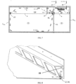
- FIG. 1 illustrates a schematic view of a ceiling assembly allowing the circulation of air within a room to be treated 1.
- room to be treated we mean a room intended to receive fresh air or to be treated according to the system implemented (ventilation system as illustrated on the Figure 1 or air conditioning system).
- the ceiling assembly implements inside the room to be treated 1 a stretched ceiling (or false ceiling) formed from a stretched canvas 3 extending between the wall walls 4a, 4b of the room to be treated 1 and fixed to them via hanging profiles and delimiting, with the upper slab 8, a plenum 14 and a plenum 16 separated in a sealed manner by a wall 11 provided with a separation profile 27.
- a stretched ceiling or false ceiling
- two of the walls of the room are provided with hanging profiles arranged to allow the passage of air between the plenums 14 and 16 and the room to be treated 1.
- hanging profiles arranged to allow the passage of air between the plenums 14 and 16 and the room to be treated 1.
- blowing profile 6a and suction profile 6b are however identical. Examples of blowing/suction profiles will be described later.
- the suction profiles 6b are fixed to the walls located opposite the walls equipped with the blowing profiles 6a. This has the advantage of obtaining optimal air sweeping of the room to be treated 1.
- the ceiling assembly further comprises a vertical dividing wall 11 arranged in the plenum 14 to delimit two spaces, one of the spaces defining a plenum space for the entry of air into the room, the other space defining a plenum space for the exit of air from the room.
- a supply plenum 14 in which the fresh air is received and of a suction plenum 16 in which the air sucked from the room to be treated 1 is received.
- the partition wall 11 is made integral at the bottom with a separation profile 27 taking up the stretched ceiling as shown in the figure. Figure 1 .
- a separation profile is known per se.
- the blowing plenum 14 is equipped with a fresh air blowing air duct 17 passing through the wall of the portion of the upper slab 8 delimiting the blowing plenum.
- the suction plenum 16 is equipped with an air suction air duct 18 passing through the portion of the upper slab delimiting the suction plenum.
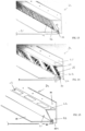
- FIG. 2 shows an example of the production of a blowing and suction profile 6a, 6b allowing the passage of air between the room to be treated 1 and the associated plenums 14 and 16 and implemented in the ceiling assembly of the Figure 1 .
- the blowing and suction profile 6a, 6b comprises a first vertical wing 60 and a second wing 61 connected to each other by a horizontal connecting wall 62.
- the first wing defines a fixing wing 60 allowing the profile to be fixed to the wall.
- the fixing wing has holes 21 for the passage of fixing means such as screws, rivets or the like.
- the fixing wing 60 extends from the connecting wall and above the latter (i.e. upwards). It is extended in the lower part by a third vertical wing 63.
- the second wing defines a hanging wing 61 allowing the canvas to be hung.
- the hanging wing converges towards the third wing.
- the hanging wing has an angle of inclination relative to the third wing at an angle of between 30 and 50 degrees, and a presence of 45 degrees.
- this attachment wing 61 carries on its internal wall directed towards the wall, an attachment means 30 for a harpoon 50 of a canvas, configured to place the harpoon of the canvas at a distance from the wall that it runs along so as to define a passage slot for the air.
- the attachment means 30 thus places the harpoon of the canvas along the lower edge of the attachment wall 61 while leaving an air passage slot between the harpoon and the wall (or the third vertical wing 63).
- the distance separating the attachment end of the means 30 can be between 0.5 and 5 cm, preferably being between 1.5 and 3 cm and more preferably of the order of 2 cm.
- the harpoon of the canvas may be provided to be elastically deformable, and the attachment means 30 may be in the form of a C-shaped hook in cross section curved towards the internal wall of the attachment wall 61 so as to form with this internal wall, a passage groove for the elastically deformed harpoon, leading to a groove for receiving the harpoon in its non-deformed configuration and a rim for blocking the harpoon received in the groove and kept at a distance from the wall 4a by the attachment wall 61 in order to allow air to pass through.
- the attachment wing defines with the third wing a slot 22 having a passage opening 22a having an opening axis substantially parallel to the wing for fixing to the wall wall.
- This thus makes it possible to ensure air blowing at the inlet of the room along the wall wall on which the blowing profile is fixed and at the outlet of the room (and therefore at the inlet of the plenum) an air suction having a trajectory substantially tangential to the wall wall carrying the suction profile.
- the slot allows, with the openings provided in the attachment wing, the passage of air between the plenum and the room.
- the blowing and suction profile 6a, 6b has passage openings 19 allowing the passage of air between the plenum and the room.
- the openings are rectangular windows aligned along the hanging wing.
- the openings may have another shape and/or be arranged differently.
- the number of openings is variable and a single opening or several openings may be provided. There may also be no openings, the profile thus configured then becoming a “classic” profile 7 for hanging the stretch ceiling.
- the hanging profiles 6a, 6b exist in different calibers, these calibers allowing to propose different widths of the slot 22 located in the lower part of the profile and therefore different sections of the opening 22a.
- the use of blowing profiles thus calibrated makes it possible to perfectly control the speed of air blown on the periphery of the walls equipped with these profiles.
- the air speed is calculated according to the flow of air blown, it is determined so as to obtain a sufficient range of the flow of air blown to reach the bottom of the vertical wall while respecting the air speeds perceived by the occupants of the very low room and therefore optimal comfort.
- the use of suction profiles thus calibrated makes it possible to control the suction speed so as to ensure optimal air sweeping.
- the blowing and suction profile 6a, 6b comprises a deflector 23 ( figure 8 ) to deflect the air flow towards the passage openings or the passage slot depending on whether the air enters through the passage slot or through the passage openings.
- a deflector has the advantage of improving the passage of air by minimizing the passage resistance to the air and therefore the air pressure losses of the profiles.
- the deflector connects the connecting wall to the third wing.
- the deflector can be of any shape (straight, curved, etc.), the optimal shape however respecting an arc of a circle as shown in the figure 8 .
- Fresh air is blown into the supply plenum via the supply duct passing through the upper slab, into the supply plenum to pass through the supply profile.
- the fresh air flows along the wall fitted with the profile.
- the sucked air is then drawn towards the stretched ceiling following a path substantially tangential to the wall provided with the suction profile to pass through the suction profile.
- the sucked air is then extracted from the supply plenum via the extraction duct.
- Adjoining room 2 is shown equipped with a stretched ceiling. It is of course obvious that this could not be equipped with a ceiling, the adjoining room not being used for the purpose of air circulation in the room to be treated, as is the case with the ceiling assemblies illustrated in the figures 3 to 7 , 11 and 12 .
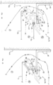
- FIG. 3 represents a particular embodiment in which the fresh air is blown into the room to be treated 1 and the air suction is carried out in an adjoining room 2.
- the room to be treated 1 is equipped with a stretched ceiling 3 delimiting with the upper slab a plenum.
- the stretched ceiling is attached to the wall walls 4a, 4b of the room via hanging profiles.
- only one of the wall walls, the furthest in the example (wall 4a) is equipped with a profile allowing the passage of air, the remaining walls being equipped with conventional hanging profiles 7 (i.e. not being arranged to allow the passage of air), these profiles 7 can also be produced by means of profiles 6a / 6b not provided with openings 19 for the passage of air on the wing 61.
- the profile is a blowing profile 6a.
- the adjoining room 2 is equipped with a stretched ceiling 5 delimiting a plenum with the upper slab a plenum 15.
- the stretched ceiling is attached to the walls of the adjoining room via hanging profiles, at least one of the hanging profiles being a suction profile 6b. If all the walls are not equipped with suction profiles 6b, the remaining walls can be equipped with conventional profiles 7 for hanging a stretched ceiling. In the example illustrated, only one wall, here the furthest from the room to be treated (wall 4c), is provided with suction profiles.
- Plenum 14 of the room to be treated 1 forms the supply plenum while plenum 15 of the adjoining room 2 forms the suction plenum.
- the sucked air passes between the volume of the treated room 1 and the volume of the adjoining room 2 via an existing or purpose-created leak between the two rooms, for example a gap under the door 4 separating the two rooms.
- the sucked air then reaches the plenum 15 via the peripheral suction slot 22 generated by the installation of suction profiles 6b.
- the sucked air will then be extracted from the plenum of the adjoining room via an air duct 18 passing through the upper slab from the plenum of the adjoining room.
- FIG. 4 represents another embodiment in which the circulating air is treated air coming from air conditioning equipment 12 located in the room adjoining the room to be treated 1.
- the ceiling assembly follows the arrangement of the ceiling assembly of the Figure 3 in which the fresh air inlet and air extraction ducts are replaced respectively by a blowing air duct 9 connected to the outlet of the air conditioning equipment and a suction air duct 10 connected to the inlet of the air conditioning equipment, the blowing duct passing through the wall separating the plenum of the room to be treated and the plenum of the adjoining room.
- the plenum of the room to be treated forms the blowing plenum while the plenum of the adjoining room forms the suction plenum.
- the treated air is blown into the plenum of the room to be treated1 by the air conditioning equipment via the blowing duct which passes through the blowing profile to run along the wall fitted with the profile.
- the sucked air passes between the volume of the treated room 1 and the volume of the adjoining room 2 via a leak between the two rooms.
- the sucked air then reaches the plenum 15 of the adjoining room via the peripheral suction slot 22 generated by the suction profile 6 where it reaches the air conditioning equipment via the suction air duct 10.
- the ceiling assembly illustrated in the Figure 5 allows this constraint to be overcome.
- the ceiling assembly implemented has a similar arrangement to the ceiling assembly of the Figure 1 . It further comprises a suction air duct 15 passing through the partition separating the suction plenum of the room to be treated and the plenum of the adjoining room in which the air conditioning equipment is installed, as well as a blowing air duct 9 passing through the partition separating the two rooms and the dividing wall 11 separating the suction plenum and the blowing plenum of the room to be treated.
- the adjoining room is equipped with a stretched ceiling 5 attached to the wall walls of the adjoining room via conventional hanging profiles 7 (i.e. not arranged to allow air to pass through).
- the sucked air reaches the suction plenum 16 through the peripheral suction slot 22 generated by the installation of the associated suction profile 6.
- the sucked air then reaches the intake of any air conditioning machinery by means of the suction air duct 10.
- the treated air is then put back into circulation via the blowing duct 9.
- the ceiling assembly thus produced makes it possible to treat a room that is very airtight (for acoustic reasons, for example) in relation to its adjoining rooms 2.
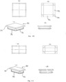
- FIG. 9 illustrates an alternative embodiment of the hanging profile not claimed.
- the hanging profile 24 has the same shape as the profile of the Figure 2 except that it further comprises a horizontal plate 25 extending under the passage openings, in a direction opposite to the third wing.
- the plate has the function of supporting a vertical partition wall without having to resort to installing a visible separator on the stretched ceiling, as illustrated in the figures 10 to 12 This improves the aesthetic appearance of the stretch ceiling while ensuring air circulation within the room.
- the suction profiles 24 are fixed on the walls located opposite the walls equipped with the blowing profiles. This has the advantage of obtaining optimal air sweeping of the room to be treated 1.
- the plate 25 can advantageously be provided with a riser at its end or with any attachment allowing the attachment of the vertical separation wall.
- blowing and suction profiles 6a, 6b, 24 can be provided with a grid arranged at the openings 19 so as to cover them.
- the presence of a grid thus makes it possible to prevent any impurity or insect from accessing the plenum 14, 15, 16) located between the upper slab and the stretched ceiling.
- the suction and blowing profile 24 has been illustrated with such a filter 26 ( Figure 13 ).
- the profiles intended for suction 6b, 24 are provided with a filter.
- This filter can then replace the filters present in the ventilation and/or air conditioning machinery connected to the system.
- the filter is removable to allow its replacement or cleaning.
- figure 14 shows a possibility of integrating such a filter into a suction profile of the type of that of the profile 24.
- the filter 28 is held against the inner face of the attachment wing 61, placed on the edge 20b delimiting the attachment groove 20 of the fabric, and is held by a longitudinal tab 28 carried by the inner face of the connecting wall 62.
- inner face we mean the faces oriented towards the slot 22.
- a profile can be provided that does not include a third wing.
- the slot will be delimited by the hanging wing of the canvas and the wall on which the profile is fixed.
- the third wing constitutes the fixing wing.
- the ceiling assembly is compatible with any air conditioning and/or ventilation technology.
- the air conditioning and/or ventilation equipment can be placed in the plenum 14 located above the room 1 to be treated, in the plenum 15 of any room adjoining the room 1 to be treated, but also in any other location in the building.
- the invention allows the implementation of any type of stretched ceiling (classic, acoustic, etc.) and allows the use of any process compatible with stretched ceilings, for example backlighting systems, sound diffusion systems, etc.
- an LED strip system could be installed at the angle between the wing 61 and the connecting wall 62 generating thus providing peripheral lighting of the room without the LED strip being visible.
- At least one wall will be equipped with a blowing profile. It will be possible to choose the walls equipped with blowing profiles 6 and therefore to choose the walls along which the treated air and/or the fresh air are blown.
- the other walls can be equipped with classic profiles 7 for hanging the stretched ceiling. This choice makes it possible to optimize the thermal comfort of the room. In particular, it will be chosen for example to blow along the exterior walls of the room, these walls being generally colder than the ambient air in winter and warmer than the ambient air in summer.
- FIG 16 illustrates another variant embodiment of a ceiling assembly, the latter comprising lighting means 40 fixed to the upper slab 8.
- the ceiling assembly illustrated has a stretched ceiling formed by two stretched canvases 3a, 3b extending between the wall walls 4a, 4b of the room to be treated. Said canvases 3a, 3b, arranged parallel to each other, are fixed to the wall walls using two hanging profiles 32, 34, one constituting a blowing profile 32, the other constituting a suction profile 34. An enlarged view of the blowing profile 32 is illustrated in the Figure 17 .
- the blowing profile 32 comprises a fixing wing 60 connected to the hanging wing 61 of canvases by a connecting wall 62.
- said wings 60, 61 are arranged so that, when the blowing profile 32 is fixed on the wall 4a, the attachment wing 61 is inclined relative to the connecting wall by converging in the direction of the wall 4a.
- the attachment wing 61 comprises two attachment grooves 20a, 20b of said fabrics 3a, 3b. One of the grooves is provided in the upper part of the attachment wing 61 with an opening on the inside of the profile, the other groove being provided in the lower part of the attachment wing 61.
- the passage openings 19 for the passage of air between the plenum 14 located above the upper stretched fabric 3b are carried by the connecting wall 62.
- the blowing profile 32 further comprises a vertical wing 64 extending from the connecting wall 62, parallel to the fixing wing 60, in a direction opposite to the attachment wing 61.
- the vertical wing 64 is provided at the end of the connecting wall 62.
- This vertical wing 64 has the function of preventing the diffusion of light coming from the light means 40 via the passage openings 19 and the passage slot 22. This will subsequently be referred to as a blocking wing 64 (or screen-forming wing).
- the ceiling assembly advantageously comprises a profile 36 of substantially V-shaped section fixed to the upper slab 8 of the room, in the vicinity of the hanging profile 32, as illustrated in the figure 16 . More particularly, the profile 36 is arranged relative to the attachment profile 32 so as to leave sufficient space between the blocking wing 64 and the profile 36 to allow the passage of air coming from the fresh air blowing air duct 17.
- the attachment profile 32 and the profile 36 constitute two separate and independent parts. These two profiles can, however, according to an alternative embodiment, constitute a single part.
- the blocking wing 64 would also comprise, like the connecting wall 62, passage openings to allow air circulation.
- the suction profile 34 takes up all the characteristics of the blowing profile 32, except that unlike the latter, it is devoid of a blocking wing.
- the diffusion of light is in fact blocked, in the ceiling assembly illustrated in the figure 16 , by the separation wall 11 of the blowing plenum 14 and the suction plenum 16 of the room.
- a suction profile 34 identical to the blowing profile 42 can also be provided without departing from the scope of the invention.
- lighting means may be provided fixed to the upper part of the hanging profile according to the invention, preferably on the face of the blocking wing 64 facing the wall 4a, 4b so as to obtain lighting at the periphery of the room or the frame.
- it may also be provided to position near the passage openings 19 a loudspeaker or any other equipment allowing the diffusion of sound in order to ensure efficient transmission of the sound.
- the blowing and suction profile 6a, 6b can be in the form of two independent parts 70, 71 to be fixed to each other.
- the first profile part 70 constitutes the fixing wing 60 and partially the horizontal connecting wall 62
- the second profile part 71 constitutes the remaining part of the horizontal connecting wall 62 and the inclined attachment wing 61.
- the first profile part 70 is defined in a particularly simple form: that of a longitudinal profile with an L-shaped section, the vertical branch of which constitutes the fixing wing 60 and the horizontal branch 73 constitutes a portion of the horizontal connecting wall 62.
- the horizontal branch of the L-shaped profile will be provided with an air passage opening 19.
- the second profile part 71 is slightly more complex and has the general shape of a longitudinal profile with a trapezoidal cross-section, the long base 74, the short base 77 and the lateral side interposed between them 75 of which form the inclined attachment wing 61, the opposite lateral side 76 which is horizontal, forming the remaining part of the horizontal connecting wall 62.
- the second profile part comprises a longitudinal groove 78 for receiving the end of the horizontal branch 73 of the L of the first profile part 70.
- An added locking means such as a screw, may be provided to engage in an orifice 79 formed on the upper surface of the end of the horizontal branch of the L to lock it, passing through the thickness of the upper lateral side of the second profile part.
- a mark 80 may be provided on the external surface of the upper lateral side 76 of the second profile part to correctly position the screw or any other locking means opposite the orifice 79 prior to its insertion therein.
- This second part of profile 71 comprises on the external surface of its lateral side 75 which is vertical, the aforementioned hook 30 allowing the passage in a deformed configuration then the blocking in a rest configuration of an elastically deformable harpoon 50 for hanging a main stretched canvas 3a.
- this second part of profile 71 can comprise a second means of attachment of an elastically deformable harpoon of a secondary stretched canvas 3b, as illustrated in the figure 18
- This second attachment means 81 is for example provided in the form of a longitudinal groove partially closed by at least one edge (two in the figure) for retaining the harpoon of the second canvas, formed from the external surface of the long base 74 of this second profile part, for example immediately under the groove 78 for receiving the end of the first profile part.
- This second canvas 3b will be able to fulfill the function of collecting and retaining deposits caused by dust and/or insects so that these remain at a distance from the main underlying canvas and cannot be visible from the room through it when, for example, it is intended to be translucent.
- the second part of the profile may also include various recesses 82 (marked on the figure 19 ) arranged in the thickness of this second profile part, between the two harpoon locking grooves to serve as housings for brackets or fixing sleeves 83 of functional elements arranged in the plenum, or simply allowing the structure of this second profile part 70 to be lightened to optimize the cost.
- Lugs 86 may be provided projecting from the wall forming these recesses to partition their space and accommodate several brackets or block them in their respective recesses.
- an inclined groove may be provided made in the thickness of this second profile part parallel to the external surface, in order to serve as a support and fixing for a blocking wing or “screen-forming wing” as presented previously.
- air passage openings 19 may be provided in this second part of the profile on the constituent walls of the small and large base in communication with each other.
- These covers 90 may have the form of parallelepiped blocks, an upper face of which is provided with a lateral edge 91 intended to be applied against the contour of the opening 19 that the cover in question closes, and a lower face of which is provided with elastically deformable blades 92 which move away as the opening passes and lock behind the contour which delimits it.
- the elastic blades extend along the length of the lateral sides of the parallelepiped block, with the exception of the corners thereof.
- Visual markers 88 in the form of excess thickness or longitudinal beads may be provided on the external surfaces of each profile part 70, 71 in order to easily and precisely connect two profile parts end to end if necessary.
- the constitution of the suction or blowing profile in two parts thus defined is particularly clever because the second part 71 more complex can be produced in large series with a single dimension, while the first part 70 of extreme simplicity can be produced with different dimensions in particular concerning the length of the branch of the L to be fixed to the second part of the profile to adjust according to the need, by a simple choice of available L profile, the desired spacing between the wall and the edge of the canvas and thus the size of the slot and the air circulation.
- the L-shaped profile of the figure 19 has a longer horizontal branch which places the edge of the main sheet 3 at a longer distance from the wall 4a than is the edge of the main sheet 3 in the variant of the embodiment of the figure 18 where the horizontal branch of the L-shaped profile is shorter.
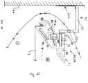
- FIG 22 represents an alternative embodiment of the blowing and suction profile 6a, 6b of the figure 19 .
- the second part of profile 71 takes on the characteristics of that illustrated on the figures 18 and 19 .
- the first part of profile 70 no longer has an L-shaped section, but a section in Z at right angles. More precisely, the first part of profile 70 is made up of two horizontal branches connected to each other by a vertical branch, said horizontal branches extending in opposite directions from each other.
- the upper horizontal branch, referenced 60 constitutes the fixing wing. It is fixed to the wall 4a via a strip forming a bracket 60b.
- the lower horizontal branch, referenced 73 constitutes a portion of the horizontal connecting wall 62.
- the vertical connecting branch, numbered 60a is provided with an air passage opening 19.
- the opening(s) provided on the first part of the profile 70 like those of the second part of profile 71, may be closed if necessary by covers as described previously.
Landscapes
- Engineering & Computer Science (AREA)
- Architecture (AREA)
- Physics & Mathematics (AREA)
- Electromagnetism (AREA)
- Civil Engineering (AREA)
- Structural Engineering (AREA)
- Mechanical Engineering (AREA)
- Combustion & Propulsion (AREA)
- Chemical & Material Sciences (AREA)
- General Engineering & Computer Science (AREA)
- Duct Arrangements (AREA)
- Vehicle Step Arrangements And Article Storage (AREA)
- Vehicle Interior And Exterior Ornaments, Soundproofing, And Insulation (AREA)
- Central Air Conditioning (AREA)
- Air-Flow Control Members (AREA)
- Treatment Of Fiber Materials (AREA)
Claims (14)
- Aufhängeprofil (6a, 6b, 24, 32, 34) eines Paneels zur Herstellung einer Spanndecke eines zu bearbeitenden Raums (1), wobei das Aufhängeprofil mindestens zwei Flügel (60, 61, 63) umfasst, die untereinander durch eine Verbindungswand (62), die sich horizontal zwischen dem Raum (1) und einem Gesamtraum (14, 16) erstreckt, verbunden sind, wobei einer der Flügel (63) angeordnet ist, um die Fixierung des Aufhängeprofils auf einer Mauerwand des zu bearbeitenden Raums zu ermöglichen, ein zweiter Flügel, der einen Aufhängeflügel (61) des Paneels darstellt, mit einem Blockierende (30) einer Klammer (50) eines Paneels ausgestattet ist, wobei die Verbindungswand (62) und der Aufhängeflügel (61) des Paneels angeordnet sind, um zusammen einen Spalt zum Durchgang von Luft (22) durch das Profil zu definieren, der nicht verschlossen und durch das Blockierende (30) der Klammer des Aufhängeflügels (61) des Paneels begrenzt ist, wobei das Profil mindestens eine Durchgangsöffnung (19) umfasst, die angeordnet ist, um den Durchgang von Luft durch das besagte Profil ausgehend von dem oder in Richtung des Spalt(s) (22) zu ermöglichen, dadurch gekennzeichnet, dass die Durchgangsöffnung (19) auf der Verbindungswand (62) angebracht ist, wobei das besagte Aufhängeprofil (6a, 6b, 24, 32, 34) entlang der gesamten Mauerwand einen offenen Spalt zum Durchgang von Luft (22) zwischen dem Gesamtraum (14, 16) und dem Raum (1) definiert, der keinerlei Element zum Verschluss oder zur Behinderung des Luftdurchgangs aufweist, und wobei das Aufhängeprofil (6a, 6b, 24, 32, 34) mindestens eine Verschlussabdeckung einer Durchgangsöffnung umfasst, wobei die Verschlussabdeckung ermöglicht, die Luftzirkulation zu begrenzen.
- Aufhängeprofil (6a, 6b, 24, 32, 34) nach Anspruch 1, dadurch gekennzeichnet, dass der Aufhängeflügel (61) des Paneels in Richtung des Flügels (63) konvergiert, wodurch die Fixierung des Aufhängeprofils oder der Mauerwand, auf der das Aufhängeprofil fixiert ist, ermöglicht wird.
- Aufhängeprofil (6a, 6b, 24, 32, 34) nach Anspruch 2, dadurch gekennzeichnet, dass es eine Durchgangsöffnung (19), die auf dem Aufhängeflügel (61) des Paneels angebracht ist, umfasst.
- Aufhängeprofil (6a, 6b, 24, 32, 34) nach Anspruch 2 oder Anspruch 3, dadurch gekennzeichnet, dass der Aufhängeflügel (61) des Paneels angeordnet ist, um einen Neigungswinkel mit Bezug auf den anderen Flügel von weniger als 90 Grad und vorzugsweise im Bereich zwischen 30 und 50 Grad darzustellen.
- Aufhängeprofil (6a, 6b, 24, 32, 34) nach irgendeinem der vorhergehenden Ansprüche, dadurch gekennzeichnet, dass die Flügel (61, 63) angeordnet sind, um einen Spalt (22), der mit der Durchgangsöffnung (19) kommuniziert, zu definieren.
- Aufhängeprofil (6a, 6b, 24, 32, 34) nach dem vorhergehenden Anspruch, dadurch gekennzeichnet, dass das Aufhängeprofil eine Ablenkplatte (23) umfasst, die in dem Spalt (22) angebracht und angeordnet ist, um den Luftfluss abzulenken, der das Profil in Richtung der Durchgangsöffnung (19) oder des Spalts (22) quert, je nachdem, ob die Luft durch den Spalt (22) oder die Durchgangsöffnung (19) eintritt.
- Aufhängeprofil (6a, 6b, 24, 32, 34) nach irgendeinem der vorhergehenden Ansprüche, dadurch gekennzeichnet, dass das Aufhängeprofil eine Platine (25), die ermöglicht, eine Trennwand zu tragen, umfasst.
- Aufhängeprofil (6a, 6b, 24, 32, 34) nach irgendeinem der vorhergehenden Ansprüche, dadurch gekennzeichnet, dass es durch die Zuordnung von zwei verschiedenen und fest miteinander verbundenen Teilen gebildet ist, wobei der erste Teil ein Profil bildet, von dem einer der Schenkel den Fixierungsflügel bildet, wobei der zweite Teil ein Profil bildet, das mit einem Mittel zur festen Verbindung mit dem ersten Teil und mit mindestens einem Mittel zur Aufhängung eines Paneels versehen ist.
- Aufhängeprofil (6a, 6b, 24, 32, 34) nach dem vorhergehenden Anspruch, dadurch gekennzeichnet, dass das Mittel zur festen Verbindung die Form eines inneren Halses zur Aufnahme des Endes eines Schenkels des ersten Teils, das in der Dicke des zweiten Profilteils durchgeführt ist, aufweist.
- Deckeneinheit, die die Zirkulation von Luft im Inneren eines zu bearbeitenden Raums (1) ermöglicht, wobei die Deckeneinheit mindestens eine Spanndecke umfasst, die mit der oberen Platte (8) des zu bearbeitenden Raums (1), unter dem sie montiert ist, einen Gesamtraum (14, 16) definiert, wobei die Spanndecke mindestens ein Spannpaneel (3, 3a, 3b) umfasst, das sich zwischen den Mauerwänden (4a, 4b) des zu bearbeitenden Raums (1) erstreckt und an diese mit Hilfe von Aufhängeprofilen fixiert ist, wobei mindestens eines der Aufhängeprofile ein Aufhängeprofil (6a, 6b, 24, 32, 34) nach irgendeinem der vorhergehenden Ansprüche ist, so dass es den Durchgang von Luft zwischen dem Gesamtraum (14, 16) und dem zu bearbeitenden Raum (1) ermöglicht, wobei die besagte Deckeneinheit und die Aufhängeprofile (6a, 6b, 24, 32, 34) gemäß einer ersten Konfiguration ermöglichen, Luft in das Innere eines gleichen Raums (1) und somit in das gleiche Volumen zu blasen und davon abzusaugen und gemäß einer zweiten Konfiguration ermöglichen, Luft in das Innere des zu bearbeitenden Raums (1) (Belüftung und/oder Klimatisierung) zu blasen und Luft von einem angrenzenden Raum (2) abzusaugen, wobei die besagte Deckeneinheit mit einem Belüftungs- und/oder Klimatisierungssystem, das fluidisch, mindestens am Eingang, mit dem Gesamtraum (14, 16) des zu bearbeitenden Raums (1) verbunden ist/sind, ausgestattet ist.
- Deckeneinheit nach dem vorhergehenden Anspruch, dadurch gekennzeichnet, dass die Flügel des Aufhängeprofils (6a, 6b, 24) angeordnet sind, um einen Spalt (22) zu definieren, der mit der Durchgangsöffnung (19) kommuniziert und so ausgerichtet ist, dass die Luft am Ausgang des Gesamtraums entlang der Mauerwand, auf der das besagte Profil fixiert ist, zirkuliert.
- Deckeneinheit nach irgendeinem der zwei vorhergehenden Ansprüche, dadurch gekennzeichnet, dass der Gesamtraum einen ersten und einen zweiten Raum umfasst, die durch eine Trennwand getrennt sind, wobei einer der Räume einen Raum des Hauptraums für den Eintritt von Luft in das Zimmer definiert, wobei der andere Raum einen Raum des Hauptraums für den Austritt von Luft aus dem Zimmer definiert.
- Deckeneinheit nach irgendeinem der Ansprüche 10 bis 12, dadurch gekennzeichnet, dass sie einen Hauptraum (15), der von einer Spanndecke, die in einem angrenzenden Raum (2) des zu bearbeitenden Raums (1) montiert ist, und der oberen Platte des angrenzenden Raums begrenzt ist, umfasst, wobei der besagte Hauptraum vom Hauptraum (14, 16) des zu bearbeitenden Raums durch eine Zwischenwand getrennt ist, die von mindestens einer Leitung, die eine fluidische Kommunikation zwischen den zwei Haupträumen ermöglicht, gequert wird.
- Deckeneinheit nach irgendeinem der Ansprüche 10 bis 13, dadurch gekennzeichnet, dass das Klimatisierungssystem in dem Hauptraum des angrenzenden Raums aufgenommen ist.
Priority Applications (4)
| Application Number | Priority Date | Filing Date | Title |
|---|---|---|---|
| SM20220499T SMT202200499T1 (it) | 2016-08-24 | 2017-08-17 | Profilo di aggancio che consente il passaggio di aria e gruppo di soffitto comprendente un tale profilo |
| HRP20221500TT HRP20221500T1 (hr) | 2016-08-24 | 2017-08-17 | Viseći profil koji omogućuje prolaženje zraka i stropni sklop koji sadrži takav profil |
| SI201731282T SI3504382T1 (sl) | 2016-08-24 | 2017-08-17 | Profil za obešanje, ki omogoča prehod zraka, in stropni sestav, ki obsega tak profil |
| RS20221149A RS63855B1 (sr) | 2016-08-24 | 2017-08-17 | Fiksirajući profil koji omogućava prolaz vazduha i plafonski sklop od kog se sastavlja takav profil |
Applications Claiming Priority (3)
| Application Number | Priority Date | Filing Date | Title |
|---|---|---|---|
| FR1657910A FR3055342A1 (fr) | 2016-08-24 | 2016-08-24 | Profile d'accroche permettant le passage d'air et ensemble de plafond comprenant un tel profile |
| FR1663456A FR3055343B1 (fr) | 2016-08-24 | 2016-12-28 | Profile d'accroche permettant le passage d'air et ensemble de plafond comprenant un tel profile |
| PCT/FR2017/052238 WO2018037184A1 (fr) | 2016-08-24 | 2017-08-17 | Profile d'accroche permettant le passage d'air et ensemble de plafond comprenant un tel profile |
Publications (3)
| Publication Number | Publication Date |
|---|---|
| EP3504382A1 EP3504382A1 (de) | 2019-07-03 |
| EP3504382B1 EP3504382B1 (de) | 2022-10-19 |
| EP3504382B2 true EP3504382B2 (de) | 2025-05-07 |
Family
ID=57796426
Family Applications (1)
| Application Number | Title | Priority Date | Filing Date |
|---|---|---|---|
| EP17768172.3A Active EP3504382B2 (de) | 2016-08-24 | 2017-08-17 | Befestigungsprofil mit luftdurchlass und eine abgehängte deckenanordnung mit einem solchen profil |
Country Status (25)
| Country | Link |
|---|---|
| US (1) | US10900229B2 (de) |
| EP (1) | EP3504382B2 (de) |
| JP (1) | JP7087244B2 (de) |
| KR (1) | KR102514029B1 (de) |
| CN (1) | CN109642427B (de) |
| AU (1) | AU2017315205B2 (de) |
| BR (1) | BR112019003633B1 (de) |
| ES (1) | ES2934339T3 (de) |
| FI (1) | FI3504382T3 (de) |
| FR (2) | FR3055342A1 (de) |
| HR (1) | HRP20221500T1 (de) |
| HU (1) | HUE060864T2 (de) |
| LT (1) | LT3504382T (de) |
| MX (1) | MX2019002257A (de) |
| MY (1) | MY198169A (de) |
| PH (1) | PH12019500352A1 (de) |
| PL (1) | PL3504382T3 (de) |
| PT (1) | PT3504382T (de) |
| RS (1) | RS63855B1 (de) |
| RU (1) | RU2745151C2 (de) |
| SA (1) | SA519401146B1 (de) |
| SG (1) | SG11201901429UA (de) |
| SI (1) | SI3504382T1 (de) |
| SM (1) | SMT202200499T1 (de) |
| WO (1) | WO2018037184A1 (de) |
Families Citing this family (18)
| Publication number | Priority date | Publication date | Assignee | Title |
|---|---|---|---|---|
| FR3055342A1 (fr) | 2016-08-24 | 2018-03-02 | Jean Marc Scherrer | Profile d'accroche permettant le passage d'air et ensemble de plafond comprenant un tel profile |
| EP3775427B1 (de) * | 2018-03-31 | 2024-10-09 | CertainTeed Ceilings Corporation | Hängedeckenbalken und hängedeckensystem mit belüftung |
| FR3085174B1 (fr) | 2018-07-03 | 2020-12-25 | Scherrer Jean Marc | Systeme d’accroche pour la realisation d’un faux-plafond tendu permettant le passage d’air |
| FR3085696B1 (fr) | 2018-09-11 | 2020-12-25 | Egis Batiments | Plafond rayonnant reversible hybride assurant chauffage, climatisation et ventilation pour le traitement d’ambiance d’un local |
| EP3663477B1 (de) * | 2018-12-03 | 2022-02-23 | Saint-Gobain Ecophon AB | Deckensystem und gebäudesystem mit solch einem deckensystem |
| RU2716623C1 (ru) * | 2019-08-26 | 2020-03-13 | Андрей Владимирович Сергелев | Способ растяжения натяжного потолка |
| FR3108641B1 (fr) * | 2020-03-24 | 2022-04-15 | Normalu | Profilé de cadre pour la réalisation d’une fausse paroi rétroéclairée et une telle fausse paroi rétroéclairée |
| FR3109623B1 (fr) | 2020-04-23 | 2022-07-15 | Scherrer Jean Marc | Panneau climatique |
| FR3112196B1 (fr) | 2020-07-02 | 2022-07-15 | Scherrer Jean Marc | Ilot climatique |
| FR3113940B1 (fr) | 2020-09-08 | 2022-08-12 | Scherrer Jean Marc | Dispositif rayonnant à condensation |
| FR3115994B1 (fr) | 2020-10-13 | 2023-03-03 | Scherrer Jean Marc | structure de plafond et installation comprenant une telle structure de plafond comprenant des moyens de stérilisation de l’air |
| CN114383239A (zh) * | 2020-10-19 | 2022-04-22 | 黄荣芳 | 厂房通风散热结构 |
| FR3129959B1 (fr) | 2021-12-03 | 2024-06-21 | Damien Lang | Plafond diffusant hybride reversible pour elements rayonnants |
| FR3130014B1 (fr) | 2021-12-03 | 2024-01-19 | Scherrer Jean Marc | Ilot climatique avec modulation de flux |
| CN114861280B (zh) * | 2022-05-27 | 2024-10-01 | 广州市圆方计算机软件工程有限公司 | 一种整装天花的建模方法及系统 |
| FR3139350B1 (fr) | 2022-09-05 | 2024-08-30 | Scherrer Jean Marc | Profile pour espaces modulaires utilisant un plenum aeraulique |
| FR3144647A1 (fr) | 2022-12-30 | 2024-07-05 | Jean-Marc Scherrer | Panneau climatique extrudé autoportant |
| FR3151048B1 (fr) | 2023-07-10 | 2025-11-07 | Normalu | Plafond climatique pour data center |
Citations (9)
| Publication number | Priority date | Publication date | Assignee | Title |
|---|---|---|---|---|
| FR2475093A1 (fr) † | 1980-02-05 | 1981-08-07 | Scherrer Fernand | Profile constituant une lisse exterieure d'un faux plafond ou un faux mur |
| FR2619531A1 (fr) † | 1987-08-18 | 1989-02-24 | Nicot Jean Pierre | Dispositif pour accrochage de plafonds ou de toiles tendues de toutes natures |
| FR2627207A1 (fr) † | 1988-02-12 | 1989-08-18 | Bidini Jean Claude | Dispositif et outil de montage de plafonds tendus |
| US5058340A (en) † | 1990-03-16 | 1991-10-22 | Muller Jurgen H | Custom stretched ceilings |
| EP0584730B1 (de) † | 1992-08-28 | 1997-06-11 | Wilhelmi Werke GmbH & Co. KG | Verfahren zum Verkleiden einer Decke und Verkleidung nach diesem Verfahren |
| WO2002031414A1 (fr) † | 2000-10-09 | 2002-04-18 | Ruhlmann, Jean-Philippe | Dispositif de climatisation |
| FR2870273A1 (fr) † | 2004-05-11 | 2005-11-18 | Rene Philippe Ruhlmann | Dispositif de maintien d'un faux plafond ou faux plancher. |
| FR3012159A1 (fr) † | 2013-10-18 | 2015-04-24 | P2R Consulting | Plafond technique a installer dans un volume ferme pour creation d'une zone fumoir |
| FR3055342A1 (fr) † | 2016-08-24 | 2018-03-02 | Jean Marc Scherrer | Profile d'accroche permettant le passage d'air et ensemble de plafond comprenant un tel profile |
Family Cites Families (32)
| Publication number | Priority date | Publication date | Assignee | Title |
|---|---|---|---|---|
| JPS5980627U (ja) * | 1982-11-25 | 1984-05-31 | 株式会社東芝 | 空気調和装置 |
| US4676016B1 (en) * | 1985-11-07 | 1995-09-05 | Harold B Phillips | Hanger for a wall covering |
| FR2597906A1 (fr) * | 1986-04-25 | 1987-10-30 | Bouttier Dominique | Dispositif d'accrochage pour faux plafond souple tendu |
| US4817699A (en) * | 1988-03-30 | 1989-04-04 | Dfb Sales, Inc. | Wall track for fabric wall coverings |
| FR2630476B1 (fr) | 1988-04-22 | 1990-08-24 | Scherrer Fernand | Faux-plafond constitue par une nappe tendue accrochee, le long de ses bords, a un support fixe aux murs d'une piece d'un batiment |
| SU1679150A1 (ru) * | 1989-09-29 | 1991-09-23 | Московский научно-исследовательский и проектный институт типового и экспериментального проектирования | Вентил ционное устройство |
| US5192348A (en) * | 1991-08-21 | 1993-03-09 | Brod & Mcclung-Pace Co. | Directional air diffuser panel for clean room ventilation system |
| FR2699613B1 (fr) * | 1992-12-08 | 1995-03-31 | Newmat Sa | Accessoire de maintien provisoire à faible distance d'une feuille souple à tendre entre deux supports. |
| FR2703761B1 (fr) * | 1993-04-06 | 1995-07-13 | Ribo Robert | Procede et dispositif de climatisation et/ou de chauffage de logements, notamment d'immeubles collectifs. |
| FR2721051B1 (fr) * | 1994-06-14 | 1996-08-30 | Alain Triboix | Dispositif pour le montage entre des parois opposées, la tension et le démontage d'une ou plusieurs membranes flexibles. |
| JPH1061050A (ja) * | 1996-08-26 | 1998-03-03 | Ig Tech Res Inc | 軒天部の外壁構造 |
| JPH10311118A (ja) * | 1997-05-12 | 1998-11-24 | Awano Seizaishiyo:Kk | 水滴防止浴室天井構造 |
| JP2000204683A (ja) * | 1999-01-12 | 2000-07-25 | Misawa Homes Co Ltd | 軒天井構造 |
| FR2811693B1 (fr) | 2000-07-13 | 2003-02-21 | Newmat Sa | Profile de lisse d'accrochage d'une nappe tendue, fausse paroi telle que faux-plafond ou faux mur comprenant un tel profile |
| JP2002327511A (ja) * | 2001-05-02 | 2002-11-15 | Kyoraku Co Ltd | プラスチック製天井材 |
| JP2004027497A (ja) * | 2002-06-21 | 2004-01-29 | Sekisui House Ltd | 軒裏見切 |
| JP4096917B2 (ja) * | 2004-06-10 | 2008-06-04 | 大成建設株式会社 | 吊り天井の制振構造 |
| US7712263B1 (en) * | 2004-08-02 | 2010-05-11 | Randall Lippie | Bird repellant device |
| US20070283656A1 (en) * | 2006-06-12 | 2007-12-13 | Anderson Andy W | Fabric Wall Panel System and Track |
| FR2914665B1 (fr) * | 2007-04-06 | 2010-03-26 | Normalu | Lisse pour fausse paroi a toile tendue |
| JP2008303697A (ja) * | 2007-06-08 | 2008-12-18 | Hokkaido | 空気清浄機能を有する天井構造 |
| US20100077686A1 (en) * | 2008-09-26 | 2010-04-01 | Dockside Canvas Co. | Decorative display |
| RU128227U1 (ru) * | 2012-12-10 | 2013-05-20 | Андрей Владимирович Сергелев | Система монтажа натяжного полотна и вентиляционная секция для нее |
| RU142080U1 (ru) * | 2014-02-11 | 2014-06-20 | Андрей Владимирович Сергелев | Несущий профиль для монтажа натяжного потолка с вентиляционными каналами |
| US9010046B1 (en) * | 2014-06-17 | 2015-04-21 | Novawell Systems, Inc. | Molding strip for fabric walls and ceilings |
| EP2977518B1 (de) * | 2014-07-24 | 2016-11-16 | Normalu | Leuchtleiste für Blindwand aus gespanntem Stoff, und eine solche Leiste umfassende Blindwand |
| RU150906U1 (ru) * | 2014-09-15 | 2015-03-10 | Ольга Викторовна Лисичкина | Натяжной потолок |
| CN204152054U (zh) * | 2014-10-27 | 2015-02-11 | 嘉兴市樱菲电器有限公司 | 一种换气吊顶 |
| CN204238405U (zh) * | 2014-11-05 | 2015-04-01 | 广州康普顿至高建材有限公司 | 一种吊顶天花的风口 |
| CN105064587B (zh) * | 2015-08-18 | 2017-08-11 | 浙江宝兰电气有限公司 | 一种用于室内空气循环净化的多功能吊顶结构 |
| US10024063B2 (en) * | 2016-03-01 | 2018-07-17 | Denis P. Friel | Weep screed |
| US10533324B2 (en) * | 2017-11-30 | 2020-01-14 | Alabama Metal Industries Corporation | Below top of wall ventilation screed device and assembly |
-
2016
- 2016-08-24 FR FR1657910A patent/FR3055342A1/fr active Pending
- 2016-12-28 FR FR1663456A patent/FR3055343B1/fr active Active
-
2017
- 2017-08-17 SG SG11201901429UA patent/SG11201901429UA/en unknown
- 2017-08-17 AU AU2017315205A patent/AU2017315205B2/en active Active
- 2017-08-17 SI SI201731282T patent/SI3504382T1/sl unknown
- 2017-08-17 SM SM20220499T patent/SMT202200499T1/it unknown
- 2017-08-17 PT PT177681723T patent/PT3504382T/pt unknown
- 2017-08-17 LT LTEPPCT/FR2017/052238T patent/LT3504382T/lt unknown
- 2017-08-17 MY MYPI2019000731A patent/MY198169A/en unknown
- 2017-08-17 BR BR112019003633-4A patent/BR112019003633B1/pt active IP Right Grant
- 2017-08-17 JP JP2019511586A patent/JP7087244B2/ja active Active
- 2017-08-17 MX MX2019002257A patent/MX2019002257A/es unknown
- 2017-08-17 WO PCT/FR2017/052238 patent/WO2018037184A1/fr not_active Ceased
- 2017-08-17 HU HUE17768172A patent/HUE060864T2/hu unknown
- 2017-08-17 US US16/327,132 patent/US10900229B2/en active Active
- 2017-08-17 HR HRP20221500TT patent/HRP20221500T1/hr unknown
- 2017-08-17 CN CN201780051700.5A patent/CN109642427B/zh active Active
- 2017-08-17 RU RU2019106121A patent/RU2745151C2/ru active
- 2017-08-17 ES ES17768172T patent/ES2934339T3/es active Active
- 2017-08-17 KR KR1020197008064A patent/KR102514029B1/ko active Active
- 2017-08-17 FI FIEP17768172.3T patent/FI3504382T3/fr active
- 2017-08-17 RS RS20221149A patent/RS63855B1/sr unknown
- 2017-08-17 EP EP17768172.3A patent/EP3504382B2/de active Active
- 2017-08-17 PL PL17768172.3T patent/PL3504382T3/pl unknown
-
2019
- 2019-02-19 PH PH12019500352A patent/PH12019500352A1/en unknown
- 2019-02-20 SA SA519401146A patent/SA519401146B1/ar unknown
Patent Citations (10)
| Publication number | Priority date | Publication date | Assignee | Title |
|---|---|---|---|---|
| FR2475093A1 (fr) † | 1980-02-05 | 1981-08-07 | Scherrer Fernand | Profile constituant une lisse exterieure d'un faux plafond ou un faux mur |
| FR2619531A1 (fr) † | 1987-08-18 | 1989-02-24 | Nicot Jean Pierre | Dispositif pour accrochage de plafonds ou de toiles tendues de toutes natures |
| FR2627207A1 (fr) † | 1988-02-12 | 1989-08-18 | Bidini Jean Claude | Dispositif et outil de montage de plafonds tendus |
| US5058340A (en) † | 1990-03-16 | 1991-10-22 | Muller Jurgen H | Custom stretched ceilings |
| EP0584730B1 (de) † | 1992-08-28 | 1997-06-11 | Wilhelmi Werke GmbH & Co. KG | Verfahren zum Verkleiden einer Decke und Verkleidung nach diesem Verfahren |
| WO2002031414A1 (fr) † | 2000-10-09 | 2002-04-18 | Ruhlmann, Jean-Philippe | Dispositif de climatisation |
| FR2870273A1 (fr) † | 2004-05-11 | 2005-11-18 | Rene Philippe Ruhlmann | Dispositif de maintien d'un faux plafond ou faux plancher. |
| FR3012159A1 (fr) † | 2013-10-18 | 2015-04-24 | P2R Consulting | Plafond technique a installer dans un volume ferme pour creation d'une zone fumoir |
| FR3055342A1 (fr) † | 2016-08-24 | 2018-03-02 | Jean Marc Scherrer | Profile d'accroche permettant le passage d'air et ensemble de plafond comprenant un tel profile |
| FR3055343A1 (fr) † | 2016-08-24 | 2018-03-02 | Jean-Marc Scherrer | Profile d'accroche permettant le passage d'air et ensemble de plafond comprenant un tel profile |
Also Published As
Similar Documents
| Publication | Publication Date | Title |
|---|---|---|
| EP3504382B2 (de) | Befestigungsprofil mit luftdurchlass und eine abgehängte deckenanordnung mit einem solchen profil | |
| EP2115363B1 (de) | Trägerstruktur zur partitionierung und/oder inneren partitionierung mit integrierter heizung und/oder kühlung | |
| FR2922919A1 (fr) | Paroi amovible destinee a etre montee sur une surface et procede de recouvrement d'une surface par une paroi amovible | |
| FR3055344A1 (fr) | Profile d'accroche permettant le passage d'air et ensemble de plafond comprenant un tel profile | |
| CA3033061C (fr) | Profile d'accroche permettant le passage d'air et ensemble de plafond comprenant un tel profile | |
| WO2008104700A2 (fr) | Dispositif de camouflage pour appareils de climatisation | |
| EP2977687B1 (de) | Kühl-, klimatisierungs- oder heizsystem mit getrennten einheiten, und gehäuse mit einer der einheiten | |
| WO2024052007A1 (fr) | Profile pour espaces modulaires utilisant un plenum aeraulique | |
| FR2963664A1 (fr) | Ensemble de pompe a chaleur et procede de montage d'un tel ensemble de pompe a chaleur dans un bati | |
| EP2309833A1 (de) | Module für Netzwerk- und Serverschränke, und ihr Einbau | |
| EP4040052B1 (de) | System mit heizmodulsatz | |
| FR2904018A1 (fr) | Construction ventilee | |
| EP3002523B1 (de) | Kühl-, klimatisierungs- oder heizsystem mit teleskopmitteln zur lufttrennung | |
| FR2620202A1 (fr) | Perfectionnements aux dispositifs concourant a la ventilation rationnelle de chacun des locaux d'un meme ensemble | |
| EP4379270A1 (de) | Vorrichtung zur reduzierung des lärms einer ausseneinheit einer wärmepumpe und wärmepumpenanordnung dafür | |
| WO2006042991A1 (fr) | Dispositif de climatisation d'un local en circuit ferme | |
| FR3108164A1 (fr) | Panneau rayonnant réversible, permettant la ventilation d’une pièce, système et construction comprenant un tel panneau | |
| FR2885202A1 (fr) | Amelioration en matiere de ventilation des batiments | |
| WO2012022877A1 (fr) | Système d'activation du transfert thermique d'une extension solaire à un bâtiment attenant et extension solaire equipee d'un tel systeme | |
| FR2960246A1 (fr) | Lanterneau d'eclairage zenithal avec protection solaire | |
| EP3587719A1 (de) | Einheit zum einbau und/oder zur renovierung eines fensters | |
| FR3055587A1 (fr) | Agencement d'un dispositif de ventilation dans un encadrement structurel de toit et vehicule comportant un tel agencement | |
| FR3022013A3 (fr) | Bouche de ventilation reglable pour systeme de circulation d'air | |
| FR2879725A1 (fr) | Dispositif de climatisation d'un local en circuit ferme, et procede de climatisation d'un local | |
| FR2873739A1 (fr) | Dispositif de paroi amovible et procede d'installation |
Legal Events
| Date | Code | Title | Description |
|---|---|---|---|
| STAA | Information on the status of an ep patent application or granted ep patent |
Free format text: STATUS: UNKNOWN |
|
| STAA | Information on the status of an ep patent application or granted ep patent |
Free format text: STATUS: THE INTERNATIONAL PUBLICATION HAS BEEN MADE |
|
| PUAI | Public reference made under article 153(3) epc to a published international application that has entered the european phase |
Free format text: ORIGINAL CODE: 0009012 |
|
| STAA | Information on the status of an ep patent application or granted ep patent |
Free format text: STATUS: REQUEST FOR EXAMINATION WAS MADE |
|
| 17P | Request for examination filed |
Effective date: 20190201 |
|
| AK | Designated contracting states |
Kind code of ref document: A1 Designated state(s): AL AT BE BG CH CY CZ DE DK EE ES FI FR GB GR HR HU IE IS IT LI LT LU LV MC MK MT NL NO PL PT RO RS SE SI SK SM TR |
|
| AX | Request for extension of the european patent |
Extension state: BA ME |
|
| DAV | Request for validation of the european patent (deleted) | ||
| DAX | Request for extension of the european patent (deleted) | ||
| STAA | Information on the status of an ep patent application or granted ep patent |
Free format text: STATUS: EXAMINATION IS IN PROGRESS |
|
| 17Q | First examination report despatched |
Effective date: 20211117 |
|
| GRAP | Despatch of communication of intention to grant a patent |
Free format text: ORIGINAL CODE: EPIDOSNIGR1 |
|
| STAA | Information on the status of an ep patent application or granted ep patent |
Free format text: STATUS: GRANT OF PATENT IS INTENDED |
|
| RIC1 | Information provided on ipc code assigned before grant |
Ipc: E04B 9/04 20060101ALI20220428BHEP Ipc: E04B 9/02 20060101ALI20220428BHEP Ipc: E04B 9/30 20060101AFI20220428BHEP |
|
| INTG | Intention to grant announced |
Effective date: 20220513 |
|
| GRAS | Grant fee paid |
Free format text: ORIGINAL CODE: EPIDOSNIGR3 |
|
| GRAA | (expected) grant |
Free format text: ORIGINAL CODE: 0009210 |
|
| STAA | Information on the status of an ep patent application or granted ep patent |
Free format text: STATUS: THE PATENT HAS BEEN GRANTED |
|
| AK | Designated contracting states |
Kind code of ref document: B1 Designated state(s): AL AT BE BG CH CY CZ DE DK EE ES FI FR GB GR HR HU IE IS IT LI LT LU LV MC MK MT NL NO PL PT RO RS SE SI SK SM TR |
|
| REG | Reference to a national code |
Ref country code: GB Ref legal event code: FG4D Free format text: NOT ENGLISH |
|
| REG | Reference to a national code |
Ref country code: CH Ref legal event code: EP |
|
| REG | Reference to a national code |
Ref country code: IE Ref legal event code: FG4D Free format text: LANGUAGE OF EP DOCUMENT: FRENCH |
|
| REG | Reference to a national code |
Ref country code: DE Ref legal event code: R096 Ref document number: 602017062791 Country of ref document: DE |
|
| REG | Reference to a national code |
Ref country code: AT Ref legal event code: REF Ref document number: 1525620 Country of ref document: AT Kind code of ref document: T Effective date: 20221115 |
|
| REG | Reference to a national code |
Ref country code: RO Ref legal event code: EPE |
|
| REG | Reference to a national code |
Ref country code: NL Ref legal event code: FP |
|
| REG | Reference to a national code |
Ref country code: PT Ref legal event code: SC4A Ref document number: 3504382 Country of ref document: PT Date of ref document: 20221230 Kind code of ref document: T Free format text: AVAILABILITY OF NATIONAL TRANSLATION Effective date: 20221223 |
|
| REG | Reference to a national code |
Ref country code: DK Ref legal event code: T3 Effective date: 20221220 |
|
| REG | Reference to a national code |
Ref country code: SE Ref legal event code: TRGR |
|
| REG | Reference to a national code |
Ref country code: HR Ref legal event code: T1PR Ref document number: P20221500 Country of ref document: HR |
|
| REG | Reference to a national code |
Ref country code: NO Ref legal event code: T2 Effective date: 20221019 |
|
| REG | Reference to a national code |
Ref country code: SK Ref legal event code: T3 Ref document number: E 40948 Country of ref document: SK |
|
| REG | Reference to a national code |
Ref country code: EE Ref legal event code: FG4A Ref document number: E022980 Country of ref document: EE Effective date: 20221218 |
|
| REG | Reference to a national code |
Ref country code: ES Ref legal event code: FG2A Ref document number: 2934339 Country of ref document: ES Kind code of ref document: T3 Effective date: 20230221 |
|
| REG | Reference to a national code |
Ref country code: GR Ref legal event code: EP Ref document number: 20220402533 Country of ref document: GR Effective date: 20230210 |
|
| REG | Reference to a national code |
Ref country code: HU Ref legal event code: AG4A Ref document number: E060864 Country of ref document: HU |
|
| REG | Reference to a national code |
Ref country code: DE Ref legal event code: R026 Ref document number: 602017062791 Country of ref document: DE |
|
| PLBI | Opposition filed |
Free format text: ORIGINAL CODE: 0009260 |
|
| PLAX | Notice of opposition and request to file observation + time limit sent |
Free format text: ORIGINAL CODE: EPIDOSNOBS2 |
|
| 26 | Opposition filed |
Opponent name: NEWMAT Effective date: 20230710 |
|
| PG25 | Lapsed in a contracting state [announced via postgrant information from national office to epo] |
Ref country code: AL Free format text: LAPSE BECAUSE OF FAILURE TO SUBMIT A TRANSLATION OF THE DESCRIPTION OR TO PAY THE FEE WITHIN THE PRESCRIBED TIME-LIMIT Effective date: 20221019 |
|
| REG | Reference to a national code |
Ref country code: AT Ref legal event code: UEP Ref document number: 1525620 Country of ref document: AT Kind code of ref document: T Effective date: 20221019 |
|
| REG | Reference to a national code |
Ref country code: HR Ref legal event code: ODRP Ref document number: P20221500 Country of ref document: HR Payment date: 20230727 Year of fee payment: 7 |
|
| PLBB | Reply of patent proprietor to notice(s) of opposition received |
Free format text: ORIGINAL CODE: EPIDOSNOBS3 |
|
| PG25 | Lapsed in a contracting state [announced via postgrant information from national office to epo] |
Ref country code: AL Free format text: LAPSE BECAUSE OF FAILURE TO SUBMIT A TRANSLATION OF THE DESCRIPTION OR TO PAY THE FEE WITHIN THE PRESCRIBED TIME-LIMIT Effective date: 20221019 |
|
| PGRI | Patent reinstated in contracting state [announced from national office to epo] |
Ref country code: AL Effective date: 20221219 |
|
| PGFP | Annual fee paid to national office [announced via postgrant information from national office to epo] |
Ref country code: NL Payment date: 20240723 Year of fee payment: 8 |
|
| REG | Reference to a national code |
Ref country code: HR Ref legal event code: ODRP Ref document number: P20221500 Country of ref document: HR Payment date: 20240731 Year of fee payment: 8 |
|
| PGFP | Annual fee paid to national office [announced via postgrant information from national office to epo] |
Ref country code: BG Payment date: 20240725 Year of fee payment: 8 |
|
| PGFP | Annual fee paid to national office [announced via postgrant information from national office to epo] |
Ref country code: HR Payment date: 20240731 Year of fee payment: 8 |
|
| PGFP | Annual fee paid to national office [announced via postgrant information from national office to epo] |
Ref country code: GR Payment date: 20240725 Year of fee payment: 8 Ref country code: DK Payment date: 20240723 Year of fee payment: 8 |
|
| PGFP | Annual fee paid to national office [announced via postgrant information from national office to epo] |
Ref country code: PT Payment date: 20240725 Year of fee payment: 8 |
|
| PGFP | Annual fee paid to national office [announced via postgrant information from national office to epo] |
Ref country code: ES Payment date: 20240902 Year of fee payment: 8 |
|
| PGFP | Annual fee paid to national office [announced via postgrant information from national office to epo] |
Ref country code: CZ Payment date: 20240726 Year of fee payment: 8 |
|
| PGFP | Annual fee paid to national office [announced via postgrant information from national office to epo] |
Ref country code: PL Payment date: 20240723 Year of fee payment: 8 |
|
| PGFP | Annual fee paid to national office [announced via postgrant information from national office to epo] |
Ref country code: SK Payment date: 20240726 Year of fee payment: 8 |
|
| PGFP | Annual fee paid to national office [announced via postgrant information from national office to epo] |
Ref country code: RO Payment date: 20240814 Year of fee payment: 8 |
|
| PGFP | Annual fee paid to national office [announced via postgrant information from national office to epo] |
Ref country code: AL Payment date: 20240822 Year of fee payment: 8 |
|
| PGFP | Annual fee paid to national office [announced via postgrant information from national office to epo] |
Ref country code: CY Payment date: 20240724 Year of fee payment: 8 |
|
| PUAH | Patent maintained in amended form |
Free format text: ORIGINAL CODE: 0009272 |
|
| STAA | Information on the status of an ep patent application or granted ep patent |
Free format text: STATUS: PATENT MAINTAINED AS AMENDED |
|
| 27A | Patent maintained in amended form |
Effective date: 20250507 |
|
| AK | Designated contracting states |
Kind code of ref document: B2 Designated state(s): AL AT BE BG CH CY CZ DE DK EE ES FI FR GB GR HR HU IE IS IT LI LT LU LV MC MK MT NL NO PL PT RO RS SE SI SK SM TR |
|
| REG | Reference to a national code |
Ref country code: DE Ref legal event code: R102 Ref document number: 602017062791 Country of ref document: DE |
|
| REG | Reference to a national code |
Ref country code: HR Ref legal event code: PBON Ref document number: P20221500 Country of ref document: HR Effective date: 20170817 |
|
| PG25 | Lapsed in a contracting state [announced via postgrant information from national office to epo] |
Ref country code: NL Free format text: LAPSE BECAUSE OF FAILURE TO SUBMIT A TRANSLATION OF THE DESCRIPTION OR TO PAY THE FEE WITHIN THE PRESCRIBED TIME-LIMIT Effective date: 20221019 |
|
| PGFP | Annual fee paid to national office [announced via postgrant information from national office to epo] |
Ref country code: SM Payment date: 20250924 Year of fee payment: 9 |
|
| PG25 | Lapsed in a contracting state [announced via postgrant information from national office to epo] |
Ref country code: PT Free format text: LAPSE BECAUSE OF FAILURE TO SUBMIT A TRANSLATION OF THE DESCRIPTION OR TO PAY THE FEE WITHIN THE PRESCRIBED TIME-LIMIT Effective date: 20250916 Ref country code: ES Free format text: LAPSE BECAUSE OF FAILURE TO SUBMIT A TRANSLATION OF THE DESCRIPTION OR TO PAY THE FEE WITHIN THE PRESCRIBED TIME-LIMIT Effective date: 20250507 |
|
| PGFP | Annual fee paid to national office [announced via postgrant information from national office to epo] |
Ref country code: FI Payment date: 20250923 Year of fee payment: 9 |
|
| PGFP | Annual fee paid to national office [announced via postgrant information from national office to epo] |
Ref country code: LT Payment date: 20250923 Year of fee payment: 9 Ref country code: DE Payment date: 20250904 Year of fee payment: 9 |
|
| PG25 | Lapsed in a contracting state [announced via postgrant information from national office to epo] |
Ref country code: GR Free format text: LAPSE BECAUSE OF FAILURE TO SUBMIT A TRANSLATION OF THE DESCRIPTION OR TO PAY THE FEE WITHIN THE PRESCRIBED TIME-LIMIT Effective date: 20250808 |
|
| PGFP | Annual fee paid to national office [announced via postgrant information from national office to epo] |
Ref country code: MC Payment date: 20250929 Year of fee payment: 9 Ref country code: NO Payment date: 20250925 Year of fee payment: 9 |
|
| PGFP | Annual fee paid to national office [announced via postgrant information from national office to epo] |
Ref country code: TR Payment date: 20250925 Year of fee payment: 9 Ref country code: IT Payment date: 20250923 Year of fee payment: 9 Ref country code: LU Payment date: 20250923 Year of fee payment: 9 |
|
| PG25 | Lapsed in a contracting state [announced via postgrant information from national office to epo] |
Ref country code: BG Free format text: LAPSE BECAUSE OF NON-PAYMENT OF DUE FEES Effective date: 20250808 |
|
| PGFP | Annual fee paid to national office [announced via postgrant information from national office to epo] |
Ref country code: HU Payment date: 20250919 Year of fee payment: 9 Ref country code: BE Payment date: 20250923 Year of fee payment: 9 Ref country code: GB Payment date: 20250916 Year of fee payment: 9 |
|
| PG25 | Lapsed in a contracting state [announced via postgrant information from national office to epo] |
Ref country code: HR Free format text: LAPSE BECAUSE OF FAILURE TO SUBMIT A TRANSLATION OF THE DESCRIPTION OR TO PAY THE FEE WITHIN THE PRESCRIBED TIME-LIMIT Effective date: 20250817 |
|
| PGFP | Annual fee paid to national office [announced via postgrant information from national office to epo] |
Ref country code: FR Payment date: 20250923 Year of fee payment: 9 Ref country code: AT Payment date: 20250926 Year of fee payment: 9 |
|
| PGFP | Annual fee paid to national office [announced via postgrant information from national office to epo] |
Ref country code: MT Payment date: 20250925 Year of fee payment: 9 Ref country code: CH Payment date: 20250923 Year of fee payment: 9 Ref country code: SE Payment date: 20250923 Year of fee payment: 9 |
|
| PG25 | Lapsed in a contracting state [announced via postgrant information from national office to epo] |
Ref country code: CZ Free format text: LAPSE BECAUSE OF FAILURE TO SUBMIT A TRANSLATION OF THE DESCRIPTION OR TO PAY THE FEE WITHIN THE PRESCRIBED TIME-LIMIT Effective date: 20221019 |
|
| PGFP | Annual fee paid to national office [announced via postgrant information from national office to epo] |
Ref country code: IE Payment date: 20250915 Year of fee payment: 9 Ref country code: RS Payment date: 20250929 Year of fee payment: 9 Ref country code: EE Payment date: 20250927 Year of fee payment: 9 |
|
| PG25 | Lapsed in a contracting state [announced via postgrant information from national office to epo] |
Ref country code: SK Free format text: LAPSE BECAUSE OF FAILURE TO SUBMIT A TRANSLATION OF THE DESCRIPTION OR TO PAY THE FEE WITHIN THE PRESCRIBED TIME-LIMIT Effective date: 20250507 |
|
| PGFP | Annual fee paid to national office [announced via postgrant information from national office to epo] |
Ref country code: IS Payment date: 20250924 Year of fee payment: 9 |
|
| PGFP | Annual fee paid to national office [announced via postgrant information from national office to epo] |
Ref country code: LV Payment date: 20250923 Year of fee payment: 9 |
|
| PGFP | Annual fee paid to national office [announced via postgrant information from national office to epo] |
Ref country code: SI Payment date: 20250930 Year of fee payment: 9 |
|
| PGFP | Annual fee paid to national office [announced via postgrant information from national office to epo] |
Ref country code: MK Payment date: 20250912 Year of fee payment: 9 |
|
| REG | Reference to a national code |
Ref country code: AT Ref legal event code: MK05 Ref document number: 1525620 Country of ref document: AT Kind code of ref document: T Effective date: 20221019 |
|
| REG | Reference to a national code |
Ref country code: SE Ref legal event code: NAV |