EP3504366B1 - Impact resistant, shrinkable knitted tubular sleeve and method of construction thereof - Google Patents
Impact resistant, shrinkable knitted tubular sleeve and method of construction thereof Download PDFInfo
- Publication number
- EP3504366B1 EP3504366B1 EP17761721.4A EP17761721A EP3504366B1 EP 3504366 B1 EP3504366 B1 EP 3504366B1 EP 17761721 A EP17761721 A EP 17761721A EP 3504366 B1 EP3504366 B1 EP 3504366B1
- Authority
- EP
- European Patent Office
- Prior art keywords
- shrinkable yarn
- yarn
- shrinkable
- wall
- knit
- Prior art date
- Legal status (The legal status is an assumption and is not a legal conclusion. Google has not performed a legal analysis and makes no representation as to the accuracy of the status listed.)
- Active
Links
Images


Classifications
-
- D—TEXTILES; PAPER
- D04—BRAIDING; LACE-MAKING; KNITTING; TRIMMINGS; NON-WOVEN FABRICS
- D04B—KNITTING
- D04B1/00—Weft knitting processes for the production of fabrics or articles not dependent on the use of particular machines; Fabrics or articles defined by such processes
- D04B1/22—Weft knitting processes for the production of fabrics or articles not dependent on the use of particular machines; Fabrics or articles defined by such processes specially adapted for knitting goods of particular configuration
- D04B1/225—Elongated tubular articles of small diameter, e.g. coverings or reinforcements for cables or hoses
-
- D—TEXTILES; PAPER
- D03—WEAVING
- D03D—WOVEN FABRICS; METHODS OF WEAVING; LOOMS
- D03D1/00—Woven fabrics designed to make specified articles
- D03D1/0035—Protective fabrics
- D03D1/0041—Cut or abrasion resistant
-
- D—TEXTILES; PAPER
- D03—WEAVING
- D03D—WOVEN FABRICS; METHODS OF WEAVING; LOOMS
- D03D15/00—Woven fabrics characterised by the material, structure or properties of the fibres, filaments, yarns, threads or other warp or weft elements used
- D03D15/50—Woven fabrics characterised by the material, structure or properties of the fibres, filaments, yarns, threads or other warp or weft elements used characterised by the properties of the yarns or threads
- D03D15/513—Woven fabrics characterised by the material, structure or properties of the fibres, filaments, yarns, threads or other warp or weft elements used characterised by the properties of the yarns or threads heat-resistant or fireproof
-
- D—TEXTILES; PAPER
- D03—WEAVING
- D03D—WOVEN FABRICS; METHODS OF WEAVING; LOOMS
- D03D15/00—Woven fabrics characterised by the material, structure or properties of the fibres, filaments, yarns, threads or other warp or weft elements used
- D03D15/50—Woven fabrics characterised by the material, structure or properties of the fibres, filaments, yarns, threads or other warp or weft elements used characterised by the properties of the yarns or threads
- D03D15/567—Shapes or effects upon shrinkage
-
- D—TEXTILES; PAPER
- D03—WEAVING
- D03D—WOVEN FABRICS; METHODS OF WEAVING; LOOMS
- D03D3/00—Woven fabrics characterised by their shape
- D03D3/02—Tubular fabrics
-
- D—TEXTILES; PAPER
- D04—BRAIDING; LACE-MAKING; KNITTING; TRIMMINGS; NON-WOVEN FABRICS
- D04B—KNITTING
- D04B1/00—Weft knitting processes for the production of fabrics or articles not dependent on the use of particular machines; Fabrics or articles defined by such processes
- D04B1/10—Patterned fabrics or articles
- D04B1/12—Patterned fabrics or articles characterised by thread material
-
- H—ELECTRICITY
- H02—GENERATION; CONVERSION OR DISTRIBUTION OF ELECTRIC POWER
- H02G—INSTALLATION OF ELECTRIC CABLES OR LINES, OR OF COMBINED OPTICAL AND ELECTRIC CABLES OR LINES
- H02G3/00—Installations of electric cables or lines or protective tubing therefor in or on buildings, equivalent structures or vehicles
- H02G3/02—Details
- H02G3/04—Protective tubing or conduits, e.g. cable ladders or cable troughs
-
- D—TEXTILES; PAPER
- D10—INDEXING SCHEME ASSOCIATED WITH SUBLASSES OF SECTION D, RELATING TO TEXTILES
- D10B—INDEXING SCHEME ASSOCIATED WITH SUBLASSES OF SECTION D, RELATING TO TEXTILES
- D10B2331/00—Fibres made from polymers obtained otherwise than by reactions only involving carbon-to-carbon unsaturated bonds, e.g. polycondensation products
-
- D—TEXTILES; PAPER
- D10—INDEXING SCHEME ASSOCIATED WITH SUBLASSES OF SECTION D, RELATING TO TEXTILES
- D10B—INDEXING SCHEME ASSOCIATED WITH SUBLASSES OF SECTION D, RELATING TO TEXTILES
- D10B2401/00—Physical properties
- D10B2401/04—Heat-responsive characteristics
-
- D—TEXTILES; PAPER
- D10—INDEXING SCHEME ASSOCIATED WITH SUBLASSES OF SECTION D, RELATING TO TEXTILES
- D10B—INDEXING SCHEME ASSOCIATED WITH SUBLASSES OF SECTION D, RELATING TO TEXTILES
- D10B2401/00—Physical properties
- D10B2401/04—Heat-responsive characteristics
- D10B2401/041—Heat-responsive characteristics thermoplastic; thermosetting
-
- D—TEXTILES; PAPER
- D10—INDEXING SCHEME ASSOCIATED WITH SUBLASSES OF SECTION D, RELATING TO TEXTILES
- D10B—INDEXING SCHEME ASSOCIATED WITH SUBLASSES OF SECTION D, RELATING TO TEXTILES
- D10B2403/00—Details of fabric structure established in the fabric forming process
- D10B2403/02—Cross-sectional features
- D10B2403/023—Fabric with at least two, predominantly unlinked, knitted or woven plies interlaced with each other at spaced locations or linked to a common internal co-extensive yarn system
- D10B2403/0231—Fabric with at least two, predominantly unlinked, knitted or woven plies interlaced with each other at spaced locations or linked to a common internal co-extensive yarn system including contracting yarn, e.g. blister fabrics
-
- D—TEXTILES; PAPER
- D10—INDEXING SCHEME ASSOCIATED WITH SUBLASSES OF SECTION D, RELATING TO TEXTILES
- D10B—INDEXING SCHEME ASSOCIATED WITH SUBLASSES OF SECTION D, RELATING TO TEXTILES
- D10B2403/00—Details of fabric structure established in the fabric forming process
- D10B2403/02—Cross-sectional features
- D10B2403/024—Fabric incorporating additional compounds
- D10B2403/0241—Fabric incorporating additional compounds enhancing mechanical properties
-
- D—TEXTILES; PAPER
- D10—INDEXING SCHEME ASSOCIATED WITH SUBLASSES OF SECTION D, RELATING TO TEXTILES
- D10B—INDEXING SCHEME ASSOCIATED WITH SUBLASSES OF SECTION D, RELATING TO TEXTILES
- D10B2505/00—Industrial
- D10B2505/12—Vehicles
Definitions
- This invention relates generally to textile sleeves for protecting elongate members, and more particularly to shrinkable knitted tubular sleeves.
- wrappable sleeves typically have a non-uniform thickness with opposite edges being overlapped on one another, and thus, the outer envelop/surface of the sleeve has a non-uniform appearance having an increased thickness region that can prevent it from being used in tight areas, or otherwise make assembly difficult.
- Another drawback to wrappable sleeves is the need to keep different sizes in stock for different diameter applications, and this further increases inventory and cost.
- tubular sleeves With regard to circumferentially continuous, tubular sleeves, as with wrappable sleeves, a need to keep different sizes in stock for different diameter applications exists. Further, tubular sleeves are commonly fixed in diameter, and as such, it can be difficult or impossible to use this type of sleeve in applications where the elongate member has one or more regions of increased size relative to the inner diameter of the sleeve, such that the sleeve will not fit over the increased size region(s), wherein the increased size region(s) could be presented by an enlarged mechanical or electrical connector, for example.
- fixed diameter tubular sleeves typically require secondary fasteners to secure them in position, such as by applying a tape about one or both of the ends and on the member extending through the sleeve, for example, and thus, they suffer from the same drawbacks discussed above for wrappable sleeves.
- the sleeve includes an elongate, knitted wall having a circumferentially continuous, tubular outer periphery extending along a central axis between opposite open ends.
- the wall includes shrinkable yarn and non-shrinkable yarn.
- the shrinkable yarn provides the wall with an ability to be radially constricted from a first, diametrically enlarged state to a second, diametrically shrunken state, wherein the shrinkable yarn and the non-shrinkable yarn are knit in alternating groups of courses with one another.
- the ratio of the diameter of the first, diametrically enlarged state to the second, diametrically shrunken state is about 1.5:1 to 5:1 or greater.
- the shrinkable yarn is knit on one of even or odd needles and the non-shrinkable yarn is knit on the other of even or odd needles.
- the shrinkable yarn is knit in one of an interlock stitch pattern or a jersey stitch pattern.
- the non-shrinkable yarn is knit in an ottoman stitch pattern.
- the non-shrinkable yarn is knit having circumferentially extending floats, wherein the floats are formed by skipping at least one even needle if the non-shrinkable yarn is knit on even needles or by skipping at least one odd needle if the non-shrinkable yarn is knit on odd needles, wherein the floats form radially inwardly facing cushions that provide enhanced impact protection to the elongate member being protected.
- the floats can be formed on 1 to 4 immediately adjacent courses.
- the shrinkable yarn can be provided as a monofilament.
- the shrinkable yarn can be provided as a multifilament.
- the non-shrinkable yarn can be provided as a monofilament.
- the non-shrinkable yarn can be provided as a multifilament.
- the non-shrinkable yarn can be an air texturized multifilament.
- the non-shrinkable yarn can be provided as at least one or more of PET, nylon, PP, PE, PPS, PEEK, and Nomex.
- the wall can have a first density when in the first, diametrically enlarged assembly state and a second density when in the second, diametrically constricted state, with the second density being about 2 times greater or more than the first density.
- the wall can be knit including low melt fusible yarn that has a melt temperature that is less than the temperature required to shrink the shrinkable yarn and less than the melt temperature of the non-shrinkable yarn.
- the low melt fusible yarn can be twisted or served with the shrinkable yarn.
- the low melt fusible yarn can be twisted or served with the non-shrinkable yarn.
- a method of constructing a knitted sleeve for routing and protecting elongate members includes knitting a wall having a circumferentially continuous, tubular outer periphery extending along a central axis between opposite open ends with shrinkable yarn and non-shrinkable yarn. Further, providing the shrinkable yarn having an ability to be shrunken to radially constrict the wall from a first, diametrically enlarged state to a second, diametrically constricted state, wherein the shrinkable yarn is knit on one of even or odd needles and the non-shrinkable yarn is knit on the other of even or odd needles.
- the method can further include knitting the wall such that the ratio of the respective diameters of the first, diametrically enlarged assembly state to the second, diametrically constricted state is about 1.5:1 to 5:1 or greater.
- the method can further include knitting the shrinkable yarn on one of even or odd needles and knitting the non-shrinkable yarn on the other of even or odd needles.
- the method can further include knitting the shrinkable yarn in one of an interlock stitch pattern or jersey stitch pattern.
- the method can further include knitting the non-shrinkable yarn in an ottoman stitch pattern.
- the method can further include knitting the non-shrinkable yarn having circumferentially extending floats, wherein the floats are formed by skipping at least one even needle if the non-shrinkable yarn is knit on even needles or by skipping at least one odd needle if the non-shrinkable yarn is knit on odd needles, wherein the floats form radially inwardly facing cushions that provide enhanced impact protection to the elongate member being protected.
- the method can further include forming the floats on 1 to 4 immediately adjacent courses.
- the method can further include providing the shrinkable yarn as a monofilament.
- the method can further include providing the shrinkable yarn as a multifilament.
- the method can further include providing the non-shrinkable yarn as a monofilament.
- the method can further include providing the non-shrinkable yarn as a multifilament.
- the method can further include providing the non-shrinkable yarn as a highly texturized multifilament.
- the method can further include providing the non-shrinkable yar as at least one or more of PET, nylon, PP, PE, PPS, PEEK, and Nomex.
- the method can further including knitting the wall having a first density when in the first, diametrically enlarged state and a second density when in the second, diametrically constricted state, with the second density being about 2 times greater or more than the first density.
- the method can further include knitting the wall including low melt fusible yarn having a melt temperature that is less than the melt temperature of the shrinkable yarn and the non-shrinkable yarn.
- the method can further include twisting or server the low melt fusible yarn with the shrinkable yarn.
- the method can further include twisting or server the low melt fusible yarn with the non-shrinkable yarn.
- the method can further include knitting the circumferentially continuous wall on a flat-bed knitting machine.
- the method can further include knitting the circumferentially continuous wall on a circular knitting machine,
- Figures 1 and 2 schematically illustrate a knitted protective tubular sleeve, referred to hereafter as sleeve 10, constructed in accordance with one aspect of the disclosure.
- the sleeve 10 is shown disposed about an elongate member 12 to be protected, with the sleeve 10 shown in a second, diametrically shrunken, fully assembled state about the elongate member 12, referred to hereafter as, assembled state, shrunken state and/or second state.
- the sleeve 10 is shown in an "as knit", first, diametrically enlarged, non-shrunken assembly state, referred to hereafter as, assembly state, non-shrunken state and/or first state.
- the sleeve 10 has an elongate, knitted wall 14 having a circumferentially continuous, tubular outer periphery, also referred to as outer surface 15, and an inner surface 16 bounding an inner cavity 17 extending along a central longitudinal axis 18 between opposite open ends 20, 22.
- the wall 14 includes at least two different types of yarn, including at least one highly shrinkable yarn 24 and at least one non-shrinkable, or substantially non-shrinkable yarn, referred to hereafter as non-shrinkable yarn 26.
- substantially non-shrinkable what is meant is that the yarn 26 is not marketed or otherwise considered by one skilled in the art as being shrinkable, and that although it may shrink somewhat, such as between about 1-10% of its original length, this is nowhere near the extent of shrinkage as provided by the highly shrinkable yarn 24, which shrinks about 20% or more of its original length.
- the wall 14 upon knitting the sleeve 10, has both circumferentially extending knit courses 28 of the shrinkable yarn 24 and circumferentially extending knit courses 30 of the non-shrinkable yarn 26 interlinked via knit stitches with one another.
- the elongate member 12 can be easily disposed through the cavity 17, such as wires, a wire harness, or conduit, for example, while the sleeve 10 is in the enlarged, non-shrunken first state.
- the elongate member 12 is able to be easily fed through the cavity 17 of the sleeve 10 without getting snagged or caught up.
- the sleeve 10 is heated to a sufficient temperature to cause the shrinkable yarns 24 to shrink lengthwise, thereby causing the wall 14 to constrict significantly in diameter into close, snug abutment with an outer surface of the elongate member 12, such in a respective ratio between about 1.5:1 to 5:1 or greater. Accordingly, the single sleeve 10 is useful to be assembled over a wide range of elongate member diameters without having to have a separate sleeve for each different diameter elongate member 12.
- the sleeve 10 is formed with the wall 14 being enlarged and stretchable such that the cavity 17 is suitably sized and can be enlarged diametrically to readily receive the elongate member 12 therethrough.
- the ratio between the first, "as knit" diameter and the second, as shrunken diameter is at least 1.5:1, and preferably 2:1 or greater, and more preferably 3:1 or greater, and as high as about 10:1 or greater.
- the elongate member 12 can still be easily inserted through the cavity 17 of the sleeve 10 while the cavity 17 is in the enlarged, non-shrunken first state.
- the wall 14 can be activated to shrink into close fit, snug abutting relation about the elongate member 12 ( Figure 1 ) via selected application of at least one of heat, fluid, and ultraviolet radiation, depending on the type of shrinkable yarn 24 used.
- the sleeve 10 becomes fixed and located about the elongate member 12 against axial dislocation without need of secondary fixation mechanisms, thereby doing away for the need for clamps, straps, tape, or the like,
- the knit wall 14 becomes densified upon being shrunken, and thus, the protective attributes of the wall 14, such as impact resistance, abrasion resistance, impermeability, among other things, are greatly increased.
- the density can increase from a first density in the non-shrunken state to a second density in the shrunken state by about 2 times or greater, and in one sample, the density increased from 169 kg/m 3 to 486 kg/m 3 , by way of example and without limitation.
- the thickness and outer envelop of the wall 14 is minimized, thereby being useful in tight areas,
- the finish thickness of the wall 14 was about 3.4 mm, by way of example and without limitation.
- the shrinkable yarn 24 can be provided as either a multifilament and/or monofilament. Further, the shrinkable yarn 24 can be provided having a denier ranging between about 50 to 10000.
- the non-shrinkable or substantially non-shrinkable yarn 26 can be provided as a multifilament(s) and/or monofilament(s) of at least one or more of PET, nylon, PP, PE, PPS, PEEK, and Nomex material yarn(s).
- the denier of the non-shrinkable yarn 26 can range from about 50 to 10000. It has been found that relatively bulky multifilaments provide the increased loft to further facilitate dampening impact forces, while also enhancing flexibility of the sleeve 10.
- the number of yarn ends, including shrinkable and non-shrinkable yarns 24, 26, can be adjusted as desired for the intended application.
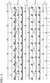
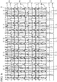
- the wall 14 of a sleeve 10, constructed in accordance with one aspect of the disclosure was knit with shrinkable and non-shrinkable yarns 24, 26, with the shrinkable yarn(s) 24 being knit in an interlock stitch pattern and the non-shrinkable yarn(s) knit in an ottoman stitch pattern ( Figure 3 ), resulting the knit structure as shown in Figure 4 .
- the shrinkable yarn 24 can be knit in a plurality of circumferentially extending courses, shown as pairs of immediately adjacent courses 28, with each pair, also referred to as group, of courses 28 of shrinkable yarn 24 being spaced from one another by a plurality of courses 30 of non-shrinkable yarn 26, shown, by way of example and without limitation, as three courses 30.
- the shrinkable yarn 24 was provided as a 0.30 mm cross-linked polyethylene monofilament and the non-shrinkable yarn 26 was provided as a 600 denier, air texturized polyethylene terephthalate (PET) multifilament, both by way of example and without limitation.
- PET polyethylene terephthalate
- the wall 14 had a non-shrunk density of about 169 kg/m 3 , and after shrinking the sleeve 10, the wail 14 had a density of about 486 kg/m 3 , with a finished, shrunken inner diameter of about 10 mm, by way of example and without limitation.
- the knitting can be performed on any suitable knitting machine capable of forming a circumferentially continuous wall, such as a flat-bed knitting machine or via a circular knitting machine, by way of example and without limitation.
- the shrinkable yarn 24 was knit on one of either even needles or odd needles, shown as being knit on each even needle within each course 28 in which the shrinkable 24 yarn is knit, by way of example and without limitation,
- the non-shrinkable yarn 26 was knit on the other of the even needles or odd needles, shown as being knit on the odd needles, by way of example and without limitation,
- the heat shrinkable yarn 24 which was knit (looped) on each even needle without skipping an even needle
- the non-shrinkable yarn 26 within at least one of the circumferentially extending courses 30 of each group of three courses 30 skips at least one needle (not looped).
- the non-shrinkable yarn 26 in the middle course 30 within each group of three courses 30 is shown as being looped about alternating odd needles (3, 7, 11%) and skipping every other odd needle (5, 9, 13%), thereby forming floats 32 of the non-shrinkable yarn 26 over the skipped needles.
- the resulting knitted structure is shown in Figure 4
- an enlarged view of a section of the structure of the non-shrinkable yarn 26 is shown in Figure 7 , with a diagrammatic view of the stitch pattern being shown in Figures 7A and 7B, as will be readily understood by one possessing ordinary skill in the knitting art.
- the floats 32 are formed by the middle non-shrinkable yarn 26 (number 2 of the three yarns 1, 2, 3) along the inner surface 16 of the wall 14, with the floats 32 extending in the circumferential direction CD.
- the floats 32 upon shrinking the sleeve 10 about the elongate member 12 and causing the wall 14 to be constricted circumferentially into a reduced diameter, snug fit with the elongate member 12 via activation of the shrinkable yarn 24 via application of heat, liquid, ultraviolet radiation, or pressure (depending on the type of heat-shrinkable yarn used), bulge and extend radially inwardly into abutment with an outer surface of the elongate member 12, as shown schematically in Figure 8 .
- the bulged floats 32 form individual radially inwardly extending, lofted pillows or cushions, and referred to hereafter as dampeners 34, which function to greatly diminish the transference of impact forces to the elongate member 12, while also acting to dampen vibration. Accordingly, the elongate member 12 is surrounded about its circumference by the plurality of bulged dampeners 34, and thus, the elongate member 12 is greatly protected against external impact forces and against sources of vibration,
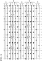
- a wall 114 of a sleeve 110 constructed in accordance with another aspect of the invention, was knit similarly that described above with regard to Figures 3 and 4 , with shrinkable yarns 24 knit in an interlock stitch pattern and the non-shrinkable yarns 26 knit in an ottoman stitch pattern ( Figure 5 ), resulting the knit structure as shown in Figure 6 .
- the shrinkable yarn 24 was knit the same as discussed above, namely, in a plurality of circumferentially extending courses, shown as pairs of immediately adjacent courses 28, with each pair of courses 28 of shrinkable yarn 24 being spaced from one another by the a plurality of courses 30 of non-shrinkable yarn 26.
- the non-shrinkable yarn 26 within at least one course 30 within each group of four courses 30 skips at least one or more needles.
- the non-shrinkable yarn 26 in the middle two courses 30 within each group of four courses 30 is shown as being looped about alternating odd needles (3, 7, 11%) and skipping every other odd needle (5, 9, 13%), thereby forming floats 32 of the non-shrinkable yarn 26 over the skipped needles.
- the resulting knitted structure is shown in Figure 6 , wherein the floats 32 within a common group of four non-shrinkable yarns 26 are formed in immediately adjacent relation one another, with the adjacent floats 32 being aligned axially with one another along a lengthwise extending direction along the longitudinal axis 18.
- the floats 32 can be positioned as desired, depending on the particular knit stitch patter used, and thus, the floats 32 within each group could be staggered circumferentially relative to one another, rather than being axially aligned, if desired. Otherwise, the knit wall 114 of the embodiment of Figures 5 and 6 is the same as discussed above, whereupon the floats 32 form radially inwardly extending dampeners 34 upon shrinking the wall 114.
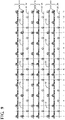
- a wall 214 of a sleeve 210 was knit similarly that described above with regard to Figures 3 and 4 , with shrinkable yarns 24; however, rather than knitting the shrinkable yarns 24 in an interlock stitch pattern, the shrinkable yarns 24 were knit in a jersey stitch pattern.
- the non-shrinkable yarns 26 were knit in an ottoman stitch pattern, resulting in the knit structure as shown in Figure 10 .
- the shrinkable yarn 24 was knit in single courses 28, with each course 28 of shrinkable yarn 24 being spaced from one another by the a plurality of courses 30 of non-shrinkable yarn 26, shown as a pair of courses 30, by way of example and without limitation.
- the non-shrinkable yarn 26 within at least one of the courses 30 of each group of courses 30 skips at least one needle.
- one of the pair of non-shrinkable yarns 26 in each group or plurality of course 30 is shown as being looped about alternating odd needles (1, 5, 9, 13%) and skipping every other odd needle (3, 7, 11%), thereby forming floats 32 of the non-shrinkable yarn 26 over the skipped needles.
- the resulting knitted structure of the wall 214 is shown in Figure 10 . This embodiment has been found particularly suitable for construction on a circular knitting machine, though other embodiments are contemplated herein, for knitting on both a flat-bed knitting machine or circular knitting machine.
- a sleeve wall 314 constructed in accordance with another aspect of the disclosure is shown, wherein similar reference numerals as used above are used to indicate like features, offset by a factor of 300 wherein appropriate to indicate a different embodiment.
- shrinkable yarn 24 and the non-shrinkable yarn 26 can further include a low melt yarn 36.
- the low melt yarn 36 can be knit with the shrinkable yarn 24 and/or the non-shrinkable yarn 26, and is shown as being served or twisted with the shrinkable yarn 24, though it can also be served or twisted with the non-shrinkable yarn 26.
- the low melt yarn 36 has a melt temperature that is less than the melt and shrinking temperature of the shrinkable yarn 24 and less than the melt temperature of the non-shrinkable yarn 26, and thus, can be readily melted, at least in part, without adversely affecting the performance of the yarns 24, 26, and further, without activating shrinkage of the shrinkable yarn 24.
- the low melt yarn 36 can be melted, and thus, bonded with the abutting shrinkable yarn 24 and the non-shrinkable yarn 26, thereby acting to prevent end fray.
- a hot blade, wire or knife by way of example and without limitation, can be used in a cutting operation of manufacture to cut the sleeve wall 314 to length, and thus, during the cutting operation, the low melt yarn 36 is simultaneously melted, thereby acting to prevent end fray without causing the shrinkable yarn 24 to be shrunk.
Landscapes
- Engineering & Computer Science (AREA)
- Textile Engineering (AREA)
- Architecture (AREA)
- Civil Engineering (AREA)
- Structural Engineering (AREA)
- Mechanical Engineering (AREA)
- Knitting Of Fabric (AREA)
- Gloves (AREA)
- Professional, Industrial, Or Sporting Protective Garments (AREA)
Applications Claiming Priority (3)
| Application Number | Priority Date | Filing Date | Title |
|---|---|---|---|
| US201662378992P | 2016-08-24 | 2016-08-24 | |
| US15/684,875 US10415162B2 (en) | 2016-08-24 | 2017-08-23 | Impact resistant, shrinkable knitted tubular sleeve and method of construction thereof |
| PCT/US2017/048304 WO2018039399A1 (en) | 2016-08-24 | 2017-08-24 | Impact resistant, shrinkable knitted tubular sleeve and method of construction thereof |
Publications (2)
| Publication Number | Publication Date |
|---|---|
| EP3504366A1 EP3504366A1 (en) | 2019-07-03 |
| EP3504366B1 true EP3504366B1 (en) | 2022-06-15 |
Family
ID=61241784
Family Applications (1)
| Application Number | Title | Priority Date | Filing Date |
|---|---|---|---|
| EP17761721.4A Active EP3504366B1 (en) | 2016-08-24 | 2017-08-24 | Impact resistant, shrinkable knitted tubular sleeve and method of construction thereof |
Country Status (7)
| Country | Link |
|---|---|
| US (1) | US10415162B2 (enExample) |
| EP (1) | EP3504366B1 (enExample) |
| JP (1) | JP7066678B2 (enExample) |
| KR (1) | KR102404351B1 (enExample) |
| CN (1) | CN109863263B (enExample) |
| BR (1) | BR112019003664A2 (enExample) |
| WO (1) | WO2018039399A1 (enExample) |
Families Citing this family (8)
| Publication number | Priority date | Publication date | Assignee | Title |
|---|---|---|---|---|
| CN106037119A (zh) * | 2016-07-25 | 2016-10-26 | 信泰(福建)科技有限公司 | 一体鞋面制造方法及一体编织鞋面 |
| US11517062B2 (en) * | 2018-05-15 | 2022-12-06 | Brian Timlick | Helmet with unique impact absorption and redirection features |
| WO2020140028A1 (en) * | 2018-12-28 | 2020-07-02 | Flex Ltd. | Plaited low-melt yarn for adhering fabric |
| CN114375353B (zh) * | 2019-09-10 | 2023-08-11 | 费德罗-莫格尔动力系公司 | 波纹编织套筒及其制造方法 |
| US11686022B2 (en) | 2020-02-11 | 2023-06-27 | Federal-Mogul Powertrain Llc | Impact resistant, wrappable, corrugated, multilayered woven sleeve and method of construction thereof |
| WO2021179278A1 (zh) * | 2020-03-13 | 2021-09-16 | 深圳市骏鼎达新材料股份有限公司 | 保护管 |
| KR102592189B1 (ko) * | 2023-02-27 | 2023-10-20 | 안켐 주식회사 | 멀티 레이어를 갖는 직물 슬리브 |
| WO2025128970A1 (en) * | 2023-12-13 | 2025-06-19 | Nike Innovate C.V. | Interlaced knitted component and methods of manufacture |
Family Cites Families (26)
| Publication number | Priority date | Publication date | Assignee | Title |
|---|---|---|---|---|
| US2738566A (en) | 1955-05-17 | 1956-03-20 | Carter William Co | Puckered knit fabric and method of producing same |
| GB1185299A (en) * | 1966-06-07 | 1970-03-25 | Courtaulds Ltd | Knitting Method |
| GB1493007A (en) * | 1975-05-12 | 1977-11-23 | Goodyear Tire & Rubber | Hose structure |
| SU1026825A1 (ru) * | 1979-12-25 | 1983-07-07 | Предприятие П/Я А-7113 | Фильтрующий материал |
| GB8921967D0 (en) | 1989-09-29 | 1989-11-15 | Raychem Sa Nv | Recoverable fabric sleeve |
| US5952067A (en) * | 1996-12-02 | 1999-09-14 | A&P Technology, Inc. | Braided structure having uncrimped strands |
| US6711920B2 (en) | 2001-11-14 | 2004-03-30 | Federal-Mogul World Wide, Inc. | Knit convolute protective sleeve |
| GB0131016D0 (en) * | 2001-12-27 | 2002-02-13 | Voith Fabrics Heidenheim Gmbh | Roll covers |
| DE10212922A1 (de) * | 2002-03-22 | 2003-10-16 | Iprotex Gmbh & Co Kg | Geflechtschlauch |
| US7395680B2 (en) * | 2004-07-20 | 2008-07-08 | Federal Mogul Worldwide, Inc. | Self-curling knitted sleeve and method of fabrication |
| FR2897877B1 (fr) | 2006-02-28 | 2008-07-11 | Fed Mogul Systems Prot Group S | Gaine de protection aux chocs d'un tuyau, notamment pour conduite de carburant |
| US20070240896A1 (en) | 2006-04-17 | 2007-10-18 | Ott Donald C Jr | Protective sleeve assembly having an integral closure member and methods of manufacture and use thereof |
| DE102007023062A1 (de) * | 2007-05-16 | 2008-11-20 | Iprotex Gmbh & Co. Kg | Verfahren zum Herstellen eines Gewebes und hierbei hergestelltes Gewebe |
| JP2009024287A (ja) * | 2007-07-20 | 2009-02-05 | Cordon Co Ltd | 吸音性スリーブ及びその製造方法 |
| WO2011090845A1 (en) | 2010-01-19 | 2011-07-28 | Mmi-Ipco, Llc | Composite textile fabrics |
| JP3166050U (ja) * | 2010-12-03 | 2011-02-17 | 藤井株式会社 | 伸縮性円筒形枕カバー布帛 |
| US20120148772A1 (en) * | 2010-12-08 | 2012-06-14 | Avula Ramesh R | Textile sleeve with protective coating and method of construction thereof |
| US20130224408A1 (en) | 2012-02-23 | 2013-08-29 | Cassie M. Malloy | Knit sleeve for an oil dip stick tube, combination thereof, method of construction thereof and method of dampening the vibration of an oil dip stick tube |
| DE102013203538A1 (de) * | 2013-03-01 | 2014-09-04 | Fränkische Industrial Pipes GmbH & Co. KG | Strickschrumpfschlauch und Verfahren zu dessen Herstellung |
| US10132012B2 (en) | 2013-03-14 | 2018-11-20 | Federal-Mogul Powertrain Llc | End-fray resistant heat-shrinkable woven sleeve, assembly therewith and methods of construction thereof |
| JP2014231665A (ja) * | 2013-04-30 | 2014-12-11 | 株式会社島精機製作所 | 凹凸のある多層編地 |
| US20160076176A1 (en) | 2014-09-17 | 2016-03-17 | Myant Capital Partners Inc. | Seamless silhouette with engineered insulation property |
| US10202714B2 (en) * | 2014-10-30 | 2019-02-12 | Federal-Mogul Powertrain Llc | Braided textile sleeve with self-sustaining expanded and contracted states and method of construction thereof |
| JP6607819B2 (ja) | 2016-04-01 | 2019-11-20 | 株式会社オオカワニット | 丸編管状構造体、その製造方法及びその製造装置 |
| JP2017212818A (ja) | 2016-05-26 | 2017-11-30 | 株式会社オートネットワーク技術研究所 | 電線保護部材、電線保護部材付電線及び電線保護部材付電線の製造方法 |
| US11168415B2 (en) * | 2016-07-01 | 2021-11-09 | Federal-Mogul Powertrain Llc | Circumferentially continuous and constrictable textile sleeve and method of construction thereof |
-
2017
- 2017-08-23 US US15/684,875 patent/US10415162B2/en active Active
- 2017-08-24 BR BR112019003664-4A patent/BR112019003664A2/pt not_active Application Discontinuation
- 2017-08-24 JP JP2019510934A patent/JP7066678B2/ja active Active
- 2017-08-24 WO PCT/US2017/048304 patent/WO2018039399A1/en not_active Ceased
- 2017-08-24 CN CN201780065708.7A patent/CN109863263B/zh active Active
- 2017-08-24 EP EP17761721.4A patent/EP3504366B1/en active Active
- 2017-08-24 KR KR1020197007177A patent/KR102404351B1/ko active Active
Also Published As
| Publication number | Publication date |
|---|---|
| CN109863263B (zh) | 2022-01-28 |
| JP7066678B2 (ja) | 2022-05-13 |
| WO2018039399A1 (en) | 2018-03-01 |
| KR20190039241A (ko) | 2019-04-10 |
| CN109863263A (zh) | 2019-06-07 |
| US20180057977A1 (en) | 2018-03-01 |
| BR112019003664A2 (pt) | 2019-05-21 |
| JP2019525023A (ja) | 2019-09-05 |
| EP3504366A1 (en) | 2019-07-03 |
| KR102404351B1 (ko) | 2022-05-31 |
| US10415162B2 (en) | 2019-09-17 |
Similar Documents
| Publication | Publication Date | Title |
|---|---|---|
| EP3504366B1 (en) | Impact resistant, shrinkable knitted tubular sleeve and method of construction thereof | |
| EP3504766B1 (en) | Impact resistant, shrinkable braided tubular sleeve and method of construction thereof | |
| US11180872B2 (en) | Impact resistant, shrinkable woven tubular sleeve and method of construction thereof | |
| EP2964820B1 (en) | Heat-shrunk textile sleeve with extended electro-functional yarn and method of construction thereof | |
| EP3478881B1 (en) | Circumferentially continuous and constrictable textile sleeve and method of construction thereof | |
| US10393307B2 (en) | Multi-cavity, shrinkable sleeve and method of construction thereof | |
| EP3387171B1 (en) | Braided, reflective textile sleeve and method of construction thereof | |
| EP3914764B1 (en) | Braided protective sleeve with heat-shrinkable yarns and method of construction thereof | |
| US20250019874A1 (en) | Multilayered, braided tubular sleeve and method of construction thereof | |
| WO2025015270A1 (en) | Multilayered, braided tubular sleeve and method of construction thereof |
Legal Events
| Date | Code | Title | Description |
|---|---|---|---|
| STAA | Information on the status of an ep patent application or granted ep patent |
Free format text: STATUS: UNKNOWN |
|
| STAA | Information on the status of an ep patent application or granted ep patent |
Free format text: STATUS: THE INTERNATIONAL PUBLICATION HAS BEEN MADE |
|
| PUAI | Public reference made under article 153(3) epc to a published international application that has entered the european phase |
Free format text: ORIGINAL CODE: 0009012 |
|
| STAA | Information on the status of an ep patent application or granted ep patent |
Free format text: STATUS: REQUEST FOR EXAMINATION WAS MADE |
|
| 17P | Request for examination filed |
Effective date: 20190305 |
|
| AK | Designated contracting states |
Kind code of ref document: A1 Designated state(s): AL AT BE BG CH CY CZ DE DK EE ES FI FR GB GR HR HU IE IS IT LI LT LU LV MC MK MT NL NO PL PT RO RS SE SI SK SM TR |
|
| AX | Request for extension of the european patent |
Extension state: BA ME |
|
| DAV | Request for validation of the european patent (deleted) | ||
| DAX | Request for extension of the european patent (deleted) | ||
| GRAP | Despatch of communication of intention to grant a patent |
Free format text: ORIGINAL CODE: EPIDOSNIGR1 |
|
| STAA | Information on the status of an ep patent application or granted ep patent |
Free format text: STATUS: GRANT OF PATENT IS INTENDED |
|
| INTG | Intention to grant announced |
Effective date: 20220127 |
|
| GRAS | Grant fee paid |
Free format text: ORIGINAL CODE: EPIDOSNIGR3 |
|
| GRAA | (expected) grant |
Free format text: ORIGINAL CODE: 0009210 |
|
| STAA | Information on the status of an ep patent application or granted ep patent |
Free format text: STATUS: THE PATENT HAS BEEN GRANTED |
|
| AK | Designated contracting states |
Kind code of ref document: B1 Designated state(s): AL AT BE BG CH CY CZ DE DK EE ES FI FR GB GR HR HU IE IS IT LI LT LU LV MC MK MT NL NO PL PT RO RS SE SI SK SM TR |
|
| REG | Reference to a national code |
Ref country code: CH Ref legal event code: EP Ref country code: GB Ref legal event code: FG4D |
|
| REG | Reference to a national code |
Ref country code: IE Ref legal event code: FG4D |
|
| REG | Reference to a national code |
Ref country code: DE Ref legal event code: R096 Ref document number: 602017058525 Country of ref document: DE |
|
| REG | Reference to a national code |
Ref country code: AT Ref legal event code: REF Ref document number: 1498468 Country of ref document: AT Kind code of ref document: T Effective date: 20220715 |
|
| REG | Reference to a national code |
Ref country code: LT Ref legal event code: MG9D |
|
| REG | Reference to a national code |
Ref country code: NL Ref legal event code: MP Effective date: 20220615 |
|
| PG25 | Lapsed in a contracting state [announced via postgrant information from national office to epo] |
Ref country code: SE Free format text: LAPSE BECAUSE OF FAILURE TO SUBMIT A TRANSLATION OF THE DESCRIPTION OR TO PAY THE FEE WITHIN THE PRESCRIBED TIME-LIMIT Effective date: 20220615 Ref country code: NO Free format text: LAPSE BECAUSE OF FAILURE TO SUBMIT A TRANSLATION OF THE DESCRIPTION OR TO PAY THE FEE WITHIN THE PRESCRIBED TIME-LIMIT Effective date: 20220915 Ref country code: LT Free format text: LAPSE BECAUSE OF FAILURE TO SUBMIT A TRANSLATION OF THE DESCRIPTION OR TO PAY THE FEE WITHIN THE PRESCRIBED TIME-LIMIT Effective date: 20220615 Ref country code: HR Free format text: LAPSE BECAUSE OF FAILURE TO SUBMIT A TRANSLATION OF THE DESCRIPTION OR TO PAY THE FEE WITHIN THE PRESCRIBED TIME-LIMIT Effective date: 20220615 Ref country code: GR Free format text: LAPSE BECAUSE OF FAILURE TO SUBMIT A TRANSLATION OF THE DESCRIPTION OR TO PAY THE FEE WITHIN THE PRESCRIBED TIME-LIMIT Effective date: 20220916 Ref country code: FI Free format text: LAPSE BECAUSE OF FAILURE TO SUBMIT A TRANSLATION OF THE DESCRIPTION OR TO PAY THE FEE WITHIN THE PRESCRIBED TIME-LIMIT Effective date: 20220615 Ref country code: BG Free format text: LAPSE BECAUSE OF FAILURE TO SUBMIT A TRANSLATION OF THE DESCRIPTION OR TO PAY THE FEE WITHIN THE PRESCRIBED TIME-LIMIT Effective date: 20220915 |
|
| REG | Reference to a national code |
Ref country code: AT Ref legal event code: MK05 Ref document number: 1498468 Country of ref document: AT Kind code of ref document: T Effective date: 20220615 |
|
| PG25 | Lapsed in a contracting state [announced via postgrant information from national office to epo] |
Ref country code: RS Free format text: LAPSE BECAUSE OF FAILURE TO SUBMIT A TRANSLATION OF THE DESCRIPTION OR TO PAY THE FEE WITHIN THE PRESCRIBED TIME-LIMIT Effective date: 20220615 Ref country code: LV Free format text: LAPSE BECAUSE OF FAILURE TO SUBMIT A TRANSLATION OF THE DESCRIPTION OR TO PAY THE FEE WITHIN THE PRESCRIBED TIME-LIMIT Effective date: 20220615 |
|
| PG25 | Lapsed in a contracting state [announced via postgrant information from national office to epo] |
Ref country code: NL Free format text: LAPSE BECAUSE OF FAILURE TO SUBMIT A TRANSLATION OF THE DESCRIPTION OR TO PAY THE FEE WITHIN THE PRESCRIBED TIME-LIMIT Effective date: 20220615 |
|
| PG25 | Lapsed in a contracting state [announced via postgrant information from national office to epo] |
Ref country code: SM Free format text: LAPSE BECAUSE OF FAILURE TO SUBMIT A TRANSLATION OF THE DESCRIPTION OR TO PAY THE FEE WITHIN THE PRESCRIBED TIME-LIMIT Effective date: 20220615 Ref country code: SK Free format text: LAPSE BECAUSE OF FAILURE TO SUBMIT A TRANSLATION OF THE DESCRIPTION OR TO PAY THE FEE WITHIN THE PRESCRIBED TIME-LIMIT Effective date: 20220615 Ref country code: RO Free format text: LAPSE BECAUSE OF FAILURE TO SUBMIT A TRANSLATION OF THE DESCRIPTION OR TO PAY THE FEE WITHIN THE PRESCRIBED TIME-LIMIT Effective date: 20220615 Ref country code: PT Free format text: LAPSE BECAUSE OF FAILURE TO SUBMIT A TRANSLATION OF THE DESCRIPTION OR TO PAY THE FEE WITHIN THE PRESCRIBED TIME-LIMIT Effective date: 20221017 Ref country code: ES Free format text: LAPSE BECAUSE OF FAILURE TO SUBMIT A TRANSLATION OF THE DESCRIPTION OR TO PAY THE FEE WITHIN THE PRESCRIBED TIME-LIMIT Effective date: 20220615 Ref country code: EE Free format text: LAPSE BECAUSE OF FAILURE TO SUBMIT A TRANSLATION OF THE DESCRIPTION OR TO PAY THE FEE WITHIN THE PRESCRIBED TIME-LIMIT Effective date: 20220615 Ref country code: CZ Free format text: LAPSE BECAUSE OF FAILURE TO SUBMIT A TRANSLATION OF THE DESCRIPTION OR TO PAY THE FEE WITHIN THE PRESCRIBED TIME-LIMIT Effective date: 20220615 Ref country code: AT Free format text: LAPSE BECAUSE OF FAILURE TO SUBMIT A TRANSLATION OF THE DESCRIPTION OR TO PAY THE FEE WITHIN THE PRESCRIBED TIME-LIMIT Effective date: 20220615 |
|
| PG25 | Lapsed in a contracting state [announced via postgrant information from national office to epo] |
Ref country code: PL Free format text: LAPSE BECAUSE OF FAILURE TO SUBMIT A TRANSLATION OF THE DESCRIPTION OR TO PAY THE FEE WITHIN THE PRESCRIBED TIME-LIMIT Effective date: 20220615 Ref country code: IS Free format text: LAPSE BECAUSE OF FAILURE TO SUBMIT A TRANSLATION OF THE DESCRIPTION OR TO PAY THE FEE WITHIN THE PRESCRIBED TIME-LIMIT Effective date: 20221015 |
|
| REG | Reference to a national code |
Ref country code: DE Ref legal event code: R097 Ref document number: 602017058525 Country of ref document: DE |
|
| PG25 | Lapsed in a contracting state [announced via postgrant information from national office to epo] |
Ref country code: MC Free format text: LAPSE BECAUSE OF FAILURE TO SUBMIT A TRANSLATION OF THE DESCRIPTION OR TO PAY THE FEE WITHIN THE PRESCRIBED TIME-LIMIT Effective date: 20220615 Ref country code: AL Free format text: LAPSE BECAUSE OF FAILURE TO SUBMIT A TRANSLATION OF THE DESCRIPTION OR TO PAY THE FEE WITHIN THE PRESCRIBED TIME-LIMIT Effective date: 20220615 |
|
| REG | Reference to a national code |
Ref country code: CH Ref legal event code: PL |
|
| PLBE | No opposition filed within time limit |
Free format text: ORIGINAL CODE: 0009261 |
|
| STAA | Information on the status of an ep patent application or granted ep patent |
Free format text: STATUS: NO OPPOSITION FILED WITHIN TIME LIMIT |
|
| PG25 | Lapsed in a contracting state [announced via postgrant information from national office to epo] |
Ref country code: LU Free format text: LAPSE BECAUSE OF NON-PAYMENT OF DUE FEES Effective date: 20220824 Ref country code: LI Free format text: LAPSE BECAUSE OF NON-PAYMENT OF DUE FEES Effective date: 20220831 Ref country code: DK Free format text: LAPSE BECAUSE OF FAILURE TO SUBMIT A TRANSLATION OF THE DESCRIPTION OR TO PAY THE FEE WITHIN THE PRESCRIBED TIME-LIMIT Effective date: 20220615 Ref country code: CH Free format text: LAPSE BECAUSE OF NON-PAYMENT OF DUE FEES Effective date: 20220831 |
|
| REG | Reference to a national code |
Ref country code: BE Ref legal event code: MM Effective date: 20220831 |
|
| 26N | No opposition filed |
Effective date: 20230316 |
|
| GBPC | Gb: european patent ceased through non-payment of renewal fee |
Effective date: 20220915 |
|
| PG25 | Lapsed in a contracting state [announced via postgrant information from national office to epo] |
Ref country code: SI Free format text: LAPSE BECAUSE OF FAILURE TO SUBMIT A TRANSLATION OF THE DESCRIPTION OR TO PAY THE FEE WITHIN THE PRESCRIBED TIME-LIMIT Effective date: 20220615 |
|
| P01 | Opt-out of the competence of the unified patent court (upc) registered |
Effective date: 20230528 |
|
| PG25 | Lapsed in a contracting state [announced via postgrant information from national office to epo] |
Ref country code: IE Free format text: LAPSE BECAUSE OF NON-PAYMENT OF DUE FEES Effective date: 20220824 Ref country code: FR Free format text: LAPSE BECAUSE OF NON-PAYMENT OF DUE FEES Effective date: 20220831 |
|
| PG25 | Lapsed in a contracting state [announced via postgrant information from national office to epo] |
Ref country code: BE Free format text: LAPSE BECAUSE OF NON-PAYMENT OF DUE FEES Effective date: 20220831 |
|
| PG25 | Lapsed in a contracting state [announced via postgrant information from national office to epo] |
Ref country code: GB Free format text: LAPSE BECAUSE OF NON-PAYMENT OF DUE FEES Effective date: 20220915 |
|
| PG25 | Lapsed in a contracting state [announced via postgrant information from national office to epo] |
Ref country code: IT Free format text: LAPSE BECAUSE OF FAILURE TO SUBMIT A TRANSLATION OF THE DESCRIPTION OR TO PAY THE FEE WITHIN THE PRESCRIBED TIME-LIMIT Effective date: 20220615 |
|
| PG25 | Lapsed in a contracting state [announced via postgrant information from national office to epo] |
Ref country code: HU Free format text: LAPSE BECAUSE OF FAILURE TO SUBMIT A TRANSLATION OF THE DESCRIPTION OR TO PAY THE FEE WITHIN THE PRESCRIBED TIME-LIMIT; INVALID AB INITIO Effective date: 20170824 |
|
| PG25 | Lapsed in a contracting state [announced via postgrant information from national office to epo] |
Ref country code: CY Free format text: LAPSE BECAUSE OF FAILURE TO SUBMIT A TRANSLATION OF THE DESCRIPTION OR TO PAY THE FEE WITHIN THE PRESCRIBED TIME-LIMIT Effective date: 20220615 |
|
| PG25 | Lapsed in a contracting state [announced via postgrant information from national office to epo] |
Ref country code: MK Free format text: LAPSE BECAUSE OF FAILURE TO SUBMIT A TRANSLATION OF THE DESCRIPTION OR TO PAY THE FEE WITHIN THE PRESCRIBED TIME-LIMIT Effective date: 20220615 |
|
| PG25 | Lapsed in a contracting state [announced via postgrant information from national office to epo] |
Ref country code: TR Free format text: LAPSE BECAUSE OF FAILURE TO SUBMIT A TRANSLATION OF THE DESCRIPTION OR TO PAY THE FEE WITHIN THE PRESCRIBED TIME-LIMIT Effective date: 20220615 |
|
| PG25 | Lapsed in a contracting state [announced via postgrant information from national office to epo] |
Ref country code: MT Free format text: LAPSE BECAUSE OF FAILURE TO SUBMIT A TRANSLATION OF THE DESCRIPTION OR TO PAY THE FEE WITHIN THE PRESCRIBED TIME-LIMIT Effective date: 20220615 |
|
| PG25 | Lapsed in a contracting state [announced via postgrant information from national office to epo] |
Ref country code: BG Free format text: LAPSE BECAUSE OF FAILURE TO SUBMIT A TRANSLATION OF THE DESCRIPTION OR TO PAY THE FEE WITHIN THE PRESCRIBED TIME-LIMIT Effective date: 20220615 |
|
| PG25 | Lapsed in a contracting state [announced via postgrant information from national office to epo] |
Ref country code: BG Free format text: LAPSE BECAUSE OF FAILURE TO SUBMIT A TRANSLATION OF THE DESCRIPTION OR TO PAY THE FEE WITHIN THE PRESCRIBED TIME-LIMIT Effective date: 20220615 |
|
| PGFP | Annual fee paid to national office [announced via postgrant information from national office to epo] |
Ref country code: DE Payment date: 20250724 Year of fee payment: 9 |
|
| REG | Reference to a national code |
Ref country code: DE Ref legal event code: R081 Ref document number: 602017058525 Country of ref document: DE Owner name: SYSTEMS PROTECTION GROUP US LLC (N.D.GES.D. ST, US Free format text: FORMER OWNER: FEDERAL-MOGUL POWERTRAIN LLC, SOUTHFIELD, MI, US |