EP3503027A1 - Élimination d'environnement chargé en imagerie pour la détection d'objets - Google Patents
Élimination d'environnement chargé en imagerie pour la détection d'objets Download PDFInfo
- Publication number
- EP3503027A1 EP3503027A1 EP18215429.4A EP18215429A EP3503027A1 EP 3503027 A1 EP3503027 A1 EP 3503027A1 EP 18215429 A EP18215429 A EP 18215429A EP 3503027 A1 EP3503027 A1 EP 3503027A1
- Authority
- EP
- European Patent Office
- Prior art keywords
- pixel
- pixels
- target
- array
- digital image
- Prior art date
- Legal status (The legal status is an assumption and is not a legal conclusion. Google has not performed a legal analysis and makes no representation as to the accuracy of the status listed.)
- Granted
Links
- 238000001514 detection method Methods 0.000 title description 8
- 230000000007 visual effect Effects 0.000 claims abstract description 25
- 238000000034 method Methods 0.000 claims description 43
- 238000005070 sampling Methods 0.000 claims description 38
- 230000002123 temporal effect Effects 0.000 description 35
- 238000010191 image analysis Methods 0.000 description 17
- 238000010586 diagram Methods 0.000 description 12
- 230000006870 function Effects 0.000 description 11
- 230000008569 process Effects 0.000 description 11
- 238000003491 array Methods 0.000 description 9
- 238000003032 molecular docking Methods 0.000 description 6
- 238000004458 analytical method Methods 0.000 description 4
- 230000005540 biological transmission Effects 0.000 description 4
- 230000008859 change Effects 0.000 description 4
- 238000004590 computer program Methods 0.000 description 4
- 230000008901 benefit Effects 0.000 description 3
- 238000003384 imaging method Methods 0.000 description 3
- 238000004364 calculation method Methods 0.000 description 2
- 230000003287 optical effect Effects 0.000 description 2
- 230000001902 propagating effect Effects 0.000 description 2
- 230000003068 static effect Effects 0.000 description 2
- 238000012935 Averaging Methods 0.000 description 1
- RYGMFSIKBFXOCR-UHFFFAOYSA-N Copper Chemical compound [Cu] RYGMFSIKBFXOCR-UHFFFAOYSA-N 0.000 description 1
- 230000001174 ascending effect Effects 0.000 description 1
- 229910052802 copper Inorganic materials 0.000 description 1
- 239000010949 copper Substances 0.000 description 1
- 230000001419 dependent effect Effects 0.000 description 1
- 238000005516 engineering process Methods 0.000 description 1
- 239000000835 fiber Substances 0.000 description 1
- 230000006872 improvement Effects 0.000 description 1
- 238000007689 inspection Methods 0.000 description 1
- 238000004519 manufacturing process Methods 0.000 description 1
- 238000012986 modification Methods 0.000 description 1
- 230000004048 modification Effects 0.000 description 1
- 238000003672 processing method Methods 0.000 description 1
- 230000002441 reversible effect Effects 0.000 description 1
- 239000004065 semiconductor Substances 0.000 description 1
Images


Classifications
-
- G—PHYSICS
- G06—COMPUTING; CALCULATING OR COUNTING
- G06V—IMAGE OR VIDEO RECOGNITION OR UNDERSTANDING
- G06V10/00—Arrangements for image or video recognition or understanding
- G06V10/20—Image preprocessing
- G06V10/255—Detecting or recognising potential candidate objects based on visual cues, e.g. shapes
-
- G—PHYSICS
- G06—COMPUTING; CALCULATING OR COUNTING
- G06T—IMAGE DATA PROCESSING OR GENERATION, IN GENERAL
- G06T7/00—Image analysis
- G06T7/10—Segmentation; Edge detection
- G06T7/194—Segmentation; Edge detection involving foreground-background segmentation
-
- G—PHYSICS
- G01—MEASURING; TESTING
- G01C—MEASURING DISTANCES, LEVELS OR BEARINGS; SURVEYING; NAVIGATION; GYROSCOPIC INSTRUMENTS; PHOTOGRAMMETRY OR VIDEOGRAMMETRY
- G01C21/00—Navigation; Navigational instruments not provided for in groups G01C1/00 - G01C19/00
- G01C21/26—Navigation; Navigational instruments not provided for in groups G01C1/00 - G01C19/00 specially adapted for navigation in a road network
- G01C21/34—Route searching; Route guidance
- G01C21/36—Input/output arrangements for on-board computers
-
- G—PHYSICS
- G06—COMPUTING; CALCULATING OR COUNTING
- G06T—IMAGE DATA PROCESSING OR GENERATION, IN GENERAL
- G06T7/00—Image analysis
- G06T7/10—Segmentation; Edge detection
- G06T7/11—Region-based segmentation
-
- G—PHYSICS
- G06—COMPUTING; CALCULATING OR COUNTING
- G06T—IMAGE DATA PROCESSING OR GENERATION, IN GENERAL
- G06T7/00—Image analysis
- G06T7/10—Segmentation; Edge detection
- G06T7/136—Segmentation; Edge detection involving thresholding
-
- G—PHYSICS
- G06—COMPUTING; CALCULATING OR COUNTING
- G06T—IMAGE DATA PROCESSING OR GENERATION, IN GENERAL
- G06T7/00—Image analysis
- G06T7/20—Analysis of motion
- G06T7/215—Motion-based segmentation
-
- G—PHYSICS
- G06—COMPUTING; CALCULATING OR COUNTING
- G06T—IMAGE DATA PROCESSING OR GENERATION, IN GENERAL
- G06T7/00—Image analysis
- G06T7/20—Analysis of motion
- G06T7/246—Analysis of motion using feature-based methods, e.g. the tracking of corners or segments
-
- G—PHYSICS
- G06—COMPUTING; CALCULATING OR COUNTING
- G06T—IMAGE DATA PROCESSING OR GENERATION, IN GENERAL
- G06T7/00—Image analysis
- G06T7/20—Analysis of motion
- G06T7/254—Analysis of motion involving subtraction of images
-
- G—PHYSICS
- G06—COMPUTING; CALCULATING OR COUNTING
- G06T—IMAGE DATA PROCESSING OR GENERATION, IN GENERAL
- G06T7/00—Image analysis
- G06T7/70—Determining position or orientation of objects or cameras
-
- G—PHYSICS
- G06—COMPUTING; CALCULATING OR COUNTING
- G06T—IMAGE DATA PROCESSING OR GENERATION, IN GENERAL
- G06T7/00—Image analysis
- G06T7/70—Determining position or orientation of objects or cameras
- G06T7/73—Determining position or orientation of objects or cameras using feature-based methods
-
- G—PHYSICS
- G06—COMPUTING; CALCULATING OR COUNTING
- G06V—IMAGE OR VIDEO RECOGNITION OR UNDERSTANDING
- G06V10/00—Arrangements for image or video recognition or understanding
- G06V10/20—Image preprocessing
- G06V10/28—Quantising the image, e.g. histogram thresholding for discrimination between background and foreground patterns
-
- G—PHYSICS
- G06—COMPUTING; CALCULATING OR COUNTING
- G06T—IMAGE DATA PROCESSING OR GENERATION, IN GENERAL
- G06T2207/00—Indexing scheme for image analysis or image enhancement
- G06T2207/10—Image acquisition modality
- G06T2207/10016—Video; Image sequence
-
- G—PHYSICS
- G06—COMPUTING; CALCULATING OR COUNTING
- G06T—IMAGE DATA PROCESSING OR GENERATION, IN GENERAL
- G06T2207/00—Indexing scheme for image analysis or image enhancement
- G06T2207/30—Subject of image; Context of image processing
- G06T2207/30212—Military
-
- G—PHYSICS
- G06—COMPUTING; CALCULATING OR COUNTING
- G06T—IMAGE DATA PROCESSING OR GENERATION, IN GENERAL
- G06T2207/00—Indexing scheme for image analysis or image enhancement
- G06T2207/30—Subject of image; Context of image processing
- G06T2207/30248—Vehicle exterior or interior
- G06T2207/30252—Vehicle exterior; Vicinity of vehicle
Definitions
- aspects described herein relate to object detection in an image, and more specifically to tracking of a target in a digital image that includes a cluttered background.
- Tracking of objects using visual imagery is important to a wide variety of applications, including surveillance, vehicle docking, and many others.
- the objects tracked can include ground vehicles, aircraft, satellites, humans, or virtually anything else that moves across the field of view.
- Visual input for tracking can be provided from visual sensors, infrared cameras, or any other imaging devices capable of providing visual input.
- a system must be able to distinguish the object of interest from the background in the imagery.
- Existing image processing methods for distinguishing an object of interest from a background are generally not effective when presented with a wide variation in pixel intensity within the background and within the target.
- One embodiment described herein is a method for controlling navigation of a vehicle by tracking the location and orientation of a target in a digital image.
- the method includes receiving a digital image captured by a visual sensor, generating a first array including a plurality of binary values related to the pixel velocity of a first plurality of pixels in the digital image as compared to corresponding pixels in a first one or more prior digital images and generating a second array including a plurality of values related to the standard deviation of pixel intensity of the first plurality of pixels in the digital image as compared to corresponding pixels in a second one or more prior digital images.
- the method further includes determining a plurality of thresholds relating to the values in the second array, identifying a plurality of target pixels and a plurality of background pixels in the digital image, based on the first array, the second array, and the plurality of thresholds, generating a binary image related to the digital image, based on the identified plurality of target pixels and the identified plurality of background pixels, and identifying at least one of a location and an orientation of the target in the digital image based on the binary image.
- the method further includes transmitting a command to a navigation system for the vehicle, to assist in navigating the vehicle toward the target, based on the identified at least one of a location and an orientation of the target.
- the method includes receiving a digital image captured by a visual sensor, generating a first array including a plurality of binary values related to the pixel velocity of a first plurality of pixels in the digital image, and generating a second array inclduign a plurality of values related to the standard deviation of pixel intensity of the first plurality of pixels in the digital image.
- the method further includes identifying a plurality of target pixels and a plurality of background pixels in the digital image, based on the first array and the second array, and identifying at least one of a location and an orientation of the target in the digital image based on the identified plurality of target pixels and a plurality of background pixels.
- Another embodiment described herein is a system, including a processor and a memory storing a program, which, when executed on the processor, performs an operation.
- the operation includes receiving a digital image captured by a visual sensor, generating a first array including a plurality of binary values related to the pixel velocity of a first plurality of pixels in the digital image, generating a second array including a plurality of values related to the standard deviation of pixel intensity of the first plurality of pixels in the digital image, identifying a plurality of target pixels and a plurality of background pixels in the digital image, based on the first array and the second array, and identifying at least one of a location and an orientation of the target in the digital image based on the identified plurality of target pixels and a plurality of background pixels
- Embodiments disclosed herein relate to improved methods, systems, and apparatus for distinguishing an object of interest from background imagery.
- One way to distinguish an object of interest from the background in a digital image is to compute a pixel threshold value that can be used to separate the target and background pixels.
- this is an relatively straightforward task, such as when tracking a brightly lit airplane across a dark night sky.
- it is relatively easy to determine a pixel intensity threshold to use in distinguishing background pixels from target pixels.
- the threshold Once the threshold has been determined, pixels with a value below the threshold are almost certainly background (e.g., dark night sky), and pixels with a value above the threshold are almost certainly the target being tracked.
- the problem is similarly straightforward, but reversed, if the target (e.g., an aircraft) is very dark, but the background is a bright day sky. In this case, the threshold divides dark pixels belonging to the target from bright pixels belonging to the sky.
- the disclosure herein relates to embodiments for extracting highly complex targets in moving, dynamic scenes where both the target and background fluctuate widely in instantaneous pixel intensity. Unlike other methods (where the background is static and the target is moving), these embodiments are capable of working on scenes where the target and background are both moving relative to the sensor. This removes many of the constraints imposed by the fixed background techniques and provides users with many more potential use cases. Furthermore, in some scenarios the the described embodiments can use a secondary threshold/discriminator based on velocity gradients, allowing more effective discrimination between background and target pixels under a wide range of clutter conditions, since these gradients can be predicted by the specific geometry of the background noise source.
- embodiments disclosed herein can be used as part of a navigation system for a vehicle, like a spacecraft.
- the vehicle's navigation system could use visual tracking to assist in docking with an object in space, like a satellite or space station. But this requires identifying both the location and orientation of a target in a potentially cluttered image including, for example, an image of the earth in the background. Further, in this scenario, the earth's spherical shape complicates location of the target within the image, because the background image will move in complex ways across the field of view of the vehicle.
- Embodiments described herein can improve on object detection in this scenario because they are less sensitive to movement between frames and are capable of handling large pixel movement between frames (for example, tens of pixels of target movement per frame).
- the vehicle's navigation system can then use the detected information about the location and orientation of the target to, for example, assist in navigating to, and docking with, the target.
- Figure 1 is an example of one scenario in which it is useful to track a target against a cluttered background.
- a vehicle 200 navigates based, at least in part, on tracking a target 110 through a visual sensor 202.
- the vehicle 200 could be a spacecraft and the target 110 could be a satellite or space station.
- the vehicle 200 has a visual sensor 202 with a field of view 120.
- the visual sensor 202 could be, for example, a camera or any other suitable visual sensor.
- the vehicle 200 can track the location and orientation of the target 110 using the visual sensor 202 to facilitate docking with the target 110. But the visual sensor 202 may also pick up a background image 150 here, an image of the earth.
- the vehicle 200 To track the target 110 using the visual sensor 202, the vehicle 200 must be able to separate pixels representing the target 110 from pixels representing the background image 150. This allows the vehicle 200 to determine the location and orientation of the target 110 the vehicle 200 can use this location and orientation to navigate to the target 110 and dock with the target 110.
- Figure 1 illustrates a spacecraft as an example vehicle according to the disclosure herein
- the embodiments herein are not limited to navigation for vehicles in space.
- the disclosed embodiments could be useful in a wide variety of scenarios in which it is desirable to track an object against a cluttered background.
- the disclosed embodiments could be used in homeland security or battlefield target tracking and interception, in military and commercial satellite imaging and tracking, in lunar and planetary exploration, in commercial and aviation imaging for manned and unmanned aerial vehicles, in military and commercial underwater exploration including mine detection and oil exploration, in sensor surveillance, in assembly line inspection, or in any other suitable application.
- FIG. 2 is a block diagram illustrating an example vehicle 200.
- the vehicle 200 includes a visual sensor 202.
- the visual sensor 202 can be a camera configured to sense visible light and/or infrared light, or any other suitable visual sensor.
- the vehicle 200 further includes a processor 204.
- the processor 204 generally retrieves and executes programming instructions stored in the memory 206.
- the processor 204 is included to be representative of a single central processing unit (CPU), multiple CPUs, a single CPU having multiple processing cores, graphics processing units (GPUs) having multiple execution paths, and the like.
- the memory 206 is generally included to be representative of electronic storage of any suitable type(s), including random access memory or non-volatile storage.
- the memory 206 generally includes program code for performing various functions related to vehicle control and target tracking.
- the program code is generally described as various functional "applications,” “components,” or “modules” within the memory 206, although alternate implementations may have different functions and/or combinations of functions.
- the vehicle control system 230 is generally configured to control the vehicle 200, including controlling navigation of the vehicle 200 through a suitable propulsion system.
- the image capture component 210 controls capture of images from the visual sensor 202. The images captured by the image capture component 210 can be used for target tracking, as described in the subsequent figures.
- the memory 206 further includes an image analysis component 220.
- the image analysis component 220 is generally used to analyze the images captured using the image capture component 210.
- the image analysis component 220 includes a velocity image generator 222.
- the velocity image generator 222 is used to generate a velocity image based on the images captured using the image capture component 210.
- the velocity image generator 222 is described in more detail with reference to subsequent figures.
- the image analysis component 220 further includes a temporal array generator.
- the temporal array generator is used to generate a temporal deviation array from images captured using the image capture component 210, and is described in more detail with reference to Figure 5 .
- the image analysis component 220 further includes a binary image generator 226.
- the binary image generator 226 is used to generate a binary image based, at least in part, on the velocity image generated by the velocity image generator 222, the temporal deviation array generated by the temporal array generator 224, and two thresholds determined by the image analysis component 220.
- the binary image generator 226 is discussed in more detail with regard to Figure 11 .
- the memory 206 further includes a storage 240.
- the storage 240 is used to store, for example, a series of binary images generated by the binary image generator 226, as discussed in more detail with regard to Figure 11 .
- the vehicle 200 further includes a propulsion system 260, used to propel the vehicle, and a navigation system 270.
- the navigation system 270 can use a location and orientation of a target, as determined by the image analysis component 220, to facilitate navigation.
- FIG 3 is an illustration of an image 310 captured by a focal plane array (FPA), for example an image captured by a visual sensor 202 and image capture component 210.
- a target 330 is shown in the image this is the target which, for example, the vehicle 200 is tracking to facilitate navigation and docking.
- the tight bounding box (TBB) 320 is an optional, but generally desirable, bounding box generated to surround the target 330.
- the TBB 320 is constructed based on a given aim point location 340.
- the TBB 320 is computed to surround an expanded image of the target 330, such that it surrounds the target closely. But the TBB is computed such that there is a margin surrounding the target 330 to ensure that the target 330 is fully surrounded by the TBB.
- the TBB can be computed based on information from additional sensors, target tracking in prior images, or any other suitable source.
- the TBB 320 can be used in target tracking. But, as noted above, the TBB is optional. It is possible, for example, to simply use the edges and four corners of the image 310, in place of a TBB 320. Depending on the target, this may be sufficient.
- Figure 4 illustrates an overview of the process by which the image analysis component 220 can generate a binary image separating the target from the background.
- Figure 5 is a flowchart depicting the same process. Figures 4 and 5 can therefore be discussed together.
- the image analysis component 220 receives a captured image, for example captured image 410 illustrated in Figure 4 . This could be, for example, an image captured by the visual sensor 202 and the image capture component 210.
- the image analysis component 220 generates velocity values for pixels in the captured image 410 located outside of the TBB. Because the pixels are located outside the TBB, the image analysis component 220 can assume that the pixels represent the background and not the target. Step 504 is discussed in more detail with regard to Figures 6 and 7 .
- the image analysis component 220 updates temporal arrays relating to the captured image 410.
- the image analysis component 220 can use, for example, two different temporal arrays: an array representing the temporal pixel intensities in the captured image 410 over a defined number of frames, and an array representing the temporal mean 2 of pixel intensities in the captured image 410 over that same defined number of frames.
- the temporal mean of a pixel is the mean intensity value of the pixel, from the first frame in a sequence through the current frame.
- the temporal mean 2 of a pixel is the mean of the squares of the intensity values of the pixel over the same sequence of frames. In an embodiment, the temporal values need only be calculated for pixels that exceed a detection threshold.
- the velocity image generator 222 generates a preliminary velocity image, for example velocity image 420 illustrated in Figure 4 .
- Velocity image 420 is a binary image with white pixels representing likely target pixels, and black pixels representing likely background pixels. The generation of velocity image 420 is discussed in more detail with regard to Figures 8 and 9 .
- the temporal array generator 224 generates temporal deviation arrays based on the temporal arrays generated in step 506.
- Image 430 in Figure 4 illustrates a temporal deviation array.
- any pixel that did not exceed the detection threshold is assigned a very large ⁇ value.
- pixels with low standard deviation values correspond to pixels for which the intensity did not change much between frames these are likely to be target pixels because the target remains generally stationary within the TBB 320 between frames. These are the black pixels in temporal deviation array 430. Pixels with higher standard deviation values correspond to pixels for which the intensity did change significantly between frames these are likely to be background pixels or target-edge pixels, because the background and target edge is expected to move between frames. These are the white and grey pixels in temporal deviation array 430.
- the image analysis component determines two different threshold values to use in estimating whether a pixel is likely a target pixel or a background pixel. This is discussed in more detail with regard to Figure 10 .
- the appropriate threshold value is applied to each pixel to generate a binary image both the temporal deviation array and the velocity image are used in this process. This is discussed in more detail with regard to Figure 11 .
- Binary image 440 is an example of a binary image generated by step 520: the white pixels represent the target pixels and the black pixels represent background pixels.
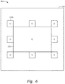
- Figure 6 is an illustration of generating pixel velocity values for a background portion of an image.
- Pixel velocity is a measure of how much an object represented by a pixel in an image is moving from frame to frame. Because the TBB 320 is assumed to enclose the target, all pixels located outside the TBB 320 should represent the background portion of the image. Therefore, measuring the pixel velocity of pixels outside the TBB 320 provides the pixel velocity for the background portion of the image. In one embodiment, the image analysis component 220 could calculate the velocity value for each pixel outside the TBB 320.
- sampling windows 610 can be any suitable size, for example n pixels x m pixels, where n and m are each positive integers.
- FIG 7 is an illustration of one method for generating pixel velocity values for the sampling windows 610 illustrated in Figure 6 .
- the velocity of the background image represented by the pixels in each sampling window 610 is computed using the peak location in the convolution between the current and previous pixels corresponding to that sampling window.
- the pixels corresponding to the sampling window 610 are found in the current image and in a previous image. These two areas are passed through a Laplace transform to bring out high frequency components, and the transformed areas are convolved to create a convolution image. From the convolution image, the shift in the location of the peak from the center gives the frame-to-frame velocity. This velocity is measured in both an x and y direction.
- image I(t) is a current frame.
- Image I(t - ⁇ t) is a previous frame.
- Sampling window 610 is the window for which we are calculating the pixel velocity.
- the pixels in sampling window 610 for image I(t) and image I(t - ⁇ t) are passed through transform 710, for example a Laplace transform.
- the results are then convolved, creating a resulting convolution image 750.
- the shift in location of the peak e.g., the grey dot shown in convolution image 750
- This velocity has both an x component, along the x-axis of the window, and a y component, along the y-axis of the window.
- calculate the location on earth that the center of the sampling window is depicting. This can be calculated using the equation R eci2fp ECI Q c2eci *(Q cam2c *R eci2fp CAM).
- R eci2fp ECI is the location on the Earth that the pixels are representing, in Earth Centered Inertial (ECI) coordinates.
- Q c2eci is the attitude of the object tracking the target, for example vehicle 200 in Figure 1 , in ECI coordinates.
- Q cam2c is the camera attitude with regard to the vehicle coordinates.
- R eci2fp CAM is a vector from the ECI origin to the center of the pixel footprint in the camera coordinates.
- R eci2fp ECI represents the previous frame's footprint location.
- R cam2eci CAM represents a vector from the camera origin to the ECI origin, in camera coordinates.
- R eci2fp CAM represents a vector from the ECI origin to the center of the pixel footprint in camera coordinates.
- the next step after generating the pixel velocity values for the background is updating the temporal arrays. This is step 506 in Figure 5 , discussed above. After that, the next step is generating the preliminary velocity image for the pixels within the TBB 320.
- Figure 8 is a flow chart illustrating this step.
- the resulting velocity image is a binary array in which every pixel set to "1" is a background pixel, and every pixel set to "0" may or may not be a target pixel. Pixels set to "0" are unknown because of the gradient method used to compute the pixel's state, discussed further with regard to steps 804-812 in Figure 8 . If the pixels in the area of interest are flat (e.g., nearly the same value as surrounding pixels), the pixels could either represent a relatively featureless portion of the target or a smooth portion of the background, like a white cloud or blue ocean if the background is the earth.
- the image analysis component 220 computes a velocity for the center pixel in each sampling window 610 outside the TBB. This is described with reference to Figures 6 and 7 .
- the velocity image generator 222 computes a gradient threshold for each sampling window 610.
- the gradient threshold can be, for example, an average gradient value for each pixel in the sampling window 610.
- the gradient threshold could be a maximum gradient value for the pixels in the sampling window 610, a minimum gradient value for the pixels in the sampling window 610, or another value.
- v x is the image velocity in the x direction for the pixel
- v y is the image velocity in the y direction for the pixel
- E x is the gradient in the x direction for the pixel
- E y is the gradient in the y direction for the pixel
- E t is the time derivative for the pixel.
- the gradient can be calculated for a 2-point derivative or a 3-point derivative.
- V x [V x] +v x
- V y [V y ]+v y
- ⁇ x ' [ V x ]
- ⁇ y ' [ V y ]
- v i V i -[ V i ] ⁇ 1
- the average 3-point gradient for small velocities can be given by the equations 13, 14, and 15, shown below.
- the goal is to select an area of an image at time t and obtain the gradient of that same area at time t+1/2. But the area may be at a different location within the image at time t+1/2, because of the large pixel velocities. Because we know the velocity, however, we can calculate the location of the area in the image at time t and time t+ ⁇ t.
- the location of the area at time t is x(t).
- ⁇ t could have any suitable value, for example, ⁇ t could be 1.
- the fractional component represents the apparent velocity relative to a chosen area.
- the gradient threshold is calculated at step 804, for each sampling window 610, by obtaining the window's fractional velocity (v x ,v y ) using the total velocity (V x ,V y ):
- v x ⁇ V x V x ⁇ 2 V x ⁇ V x + 1 V x ⁇ 2 V x + V x ⁇ 1 V x ⁇ ⁇ 2 and
- v y ⁇ V y V y ⁇ 2 V y ⁇ V y + 1 V y ⁇ 2 V y + V y ⁇ 1 V y ⁇ ⁇ 2
- the velocity image generator 222 finds the shift in position of a time t image pixel from a previous frame (t) to a current frame (t+1) (e.g., given a background pixel in the previous frame, find that same pixel's location in the current frame).
- the velocity image generator 222 then calculates the absolute value of the gradient equation.
- the velocity image generator 222 then computes the maximum gradient equation value (Grad max ) for the pixels in each sampling window 610, as well as the average (M GradEq ) and standard deviation ( ⁇ ) for the gradient equation values.
- the gradient threshold is further checked using a running average filter for the sampling window's gradient threshold. If the gradient threshold falls within three standard deviations of the running average, then the threshold is considered valid, and the running average is updated. The final gradient threshold for the window is obtained from the running average. If no final gradient threshold can be determined, the sampling window is tagged as invalid and assigned a value using the average of its two nearest valid neighbors.
- the velocity image generator 222 computes velocity and gradient values for a center window located inside the TBB at the center of the sampling windows 610a-d. This is illustrated in Figure 9 . Eight sampling windows 610 are located outside the TBB 320 within the image 310. A center window 910 is located at the center of the sampling windows 610a-d.
- the velocity image generator 222 determines whether all pixels in the velocity image have been processed. If so, the process ends. If not, the process proceeds to step 810.
- the velocity, gradient threshold, and gradient are determined for each pixel in the velocity image. Each pixel is classified as being inside the TBB 320, or outside the TBB 320. If the pixel is outside the TBB 320, the pixel's velocity and gradient threshold are the value of the closest sampling window 610.
- the absolute value of the gradient for each pixel is compared with the gradient threshold for the pixel.
- the pixel is tagged as a background pixel and the value in the velocity image corresponding to that pixel is set to 1. Otherwise, at step 816, the pixel is tagged as a target pixel and the binary value is set to 0.
- the velocity image generator 222 then returns to step 808.
- the next step is to generate the temporal deviation arrays: this is discussed with regard to step 510 in Figure 5 .
- the temporal deviation array is generated, it is copied and sorted in an ascending order into a linear array.
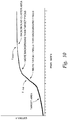
- Figure 10 illustrates determining two pixel threshold values, a lower threshold and a higher threshold, using this sorted linear array of temporal deviation values for the pixels in the image.
- the y axis represents the standard deviation of the temporal value for each pixel, as discussed above with regard to step 510 in Figure 5 .
- the x axis is the pixel index (e.g., the index of the pixel in the sorted linear array). In this graph, pixels with lower values are expected to be target pixels (less change in pixel intensity between frames) and pixels with higher values are expected to be background pixels (more change in pixel intensity between frames).
- the lower threshold can be determined by finding the maximum slope of the sorted linear array.
- the lower threshold could be the standard deviation value at the point in the curve marked T low in Figure 10 .
- the higher threshold can be found by finding the value of the sorted linear array at the index given by the expected number of pixels in the target portion of the image. This index can be found by multiplying the expected number of pixels in the target portion by 1.5.
- the expected number of pixels for the target can come from previous target images or from a library image of the target.
- the higher threshold is denoted, for example, as T high in Figure 10 .
- Each threshold can be further checked against its own corresponding running sum filter.
- Figure 11 illustrates generating the binary image.
- the binary image generator 226 generates a preliminary binary image by copying the velocity image into the binary image, reversing the binary values where the velocity image had a value of "1", the binary image is set to "0", and where the velocity image had a value of "0", the binary image is set to "1".
- the pixels set to "1" in the preliminary binary image thus represent possible target pixels.
- a small NxN window is created around each pixel in the binary array.
- N could be 2% of the size of TBB 320.
- each pixel is analyzed to determine whether it is preliminarily marked as a target pixel. If the pixel is preliminarily marked as a target pixel, at step 1110 the binary image generator 226 identifies the corresponding pixel in the temporal deviation array. The binary image generator 226 also identifies the pixels in the NxN window associated with the subject pixel, in the temporal deviation array. The temporal deviation array value for each pixel is compared with the higher threshold T high determined earlier (as described in connection with Figure 10 ). If the temporal deviation value is ⁇ T high , the corresponding pixel in the binary image is marked as "1", denoting a target pixel. This more generous threshold is used because the pixel is presumed to be a target pixel.
- Step 1108 proceeds similarly to step 1110, except the lower threshold value T low is used for the comparison.
- the binary image generator 226 identifies the corresponding pixel in the temporal deviation array.
- the binary image generator 226 also identifies the pixels in the NxN window associated with the subject pixel, in the temporal deviation array.
- the temporal deviation array value for each pixel is compared with the lower threshold value T low determined earlier (as described in connection with Figure 10 ). If the temporal deviation value is ⁇ T high , the corresponding pixel in the binary image is marked as "1", denoting a target pixel. This less generous threshold is used because the pixel is presumed to be a background pixel, and not a target pixel.
- the image analysis component stores the binary image for use by, for example, a vehicle's navigation system.
- a vehicle's navigation system e.g., navigation system 270 of vehicle 200
- aspects of the present disclosure may take the form of an entirely hardware embodiment, an entirely software embodiment (including firmware, resident software, micro-code, etc.) or an embodiment combining software and hardware aspects that may all generally be referred to herein as a "circuit,” “module” or “system.”
- Embodiment of the present disclosure may be a system, a method, and/or a computer program product.
- the computer program product may include a computer readable storage medium (or media) having computer readable program instructions thereon for causing a processor to carry out aspects of the present disclosure.
- the computer readable storage medium can be a tangible device that can retain and store instructions for use by an instruction execution device.
- the computer readable storage medium may be, for example, but is not limited to, an electronic storage device, a magnetic storage device, an optical storage device, an electromagnetic storage device, a semiconductor storage device, or any suitable combination of the foregoing.
- a non-exhaustive list of more specific examples of the computer readable storage medium includes the following: a portable computer diskette, a hard disk, a random access memory (RAM), a read-only memory (ROM), an erasable programmable read-only memory (EPROM or Flash memory), a static random access memory (SRAM), a portable compact disc read-only memory (CD-ROM), a digital versatile disk (DVD), a memory stick, a floppy disk, a mechanically encoded device such as punch-cards or raised structures in a groove having instructions recorded thereon, and any suitable combination of the foregoing.
- RAM random access memory
- ROM read-only memory
- EPROM or Flash memory erasable programmable read-only memory
- SRAM static random access memory
- CD-ROM compact disc read-only memory
- DVD digital versatile disk
- memory stick a floppy disk
- a mechanically encoded device such as punch-cards or raised structures in a groove having instructions recorded thereon
- a computer readable storage medium is not to be construed as being transitory signals per se, such as radio waves or other freely propagating electromagnetic waves, electromagnetic waves propagating through a waveguide or other transmission media (e.g., light pulses passing through a fiber-optic cable), or electrical signals transmitted through a wire.
- Computer readable program instructions described herein can be downloaded to respective computing/processing devices from a computer readable storage medium or to an external computer or external storage device via a network, for example, the Internet, a local area network, a wide area network and/or a wireless network.
- the network may comprise copper transmission cables, optical transmission fibers, wireless transmission, routers, firewalls, switches, gateway computers and/or edge servers.
- a network adapter card or network interface in each computing/processing device receives computer readable program instructions from the network and forwards the computer readable program instructions for storage in a computer readable storage medium within the respective computing/processing device.
- Computer readable program instructions for carrying out operations of the present disclosure may be assembler instructions, instruction-set-architecture (ISA) instructions, machine instructions, machine dependent instructions, microcode, firmware instructions, state-setting data, or either source code or object code written in any combination of one or more programming languages, including an object oriented programming language such as Smalltalk, C++ or the like, and conventional procedural programming languages, such as the "C" programming language or similar programming languages.
- the computer readable program instructions may execute entirely on the user's computer, partly on the user's computer, as a stand-alone software package, partly on the user's computer and partly on a remote computer or entirely on the remote computer or server.
- the remote computer may be connected to the user's computer through any type of network, including a local area network (LAN) or a wide area network (WAN), or the connection may be made to an external computer (for example, through the Internet using an Internet Service Provider).
- electronic circuitry including, for example, programmable logic circuitry, field-programmable gate arrays (FPGA), or programmable logic arrays (PLA) may execute the computer readable program instructions by utilizing state information of the computer readable program instructions to personalize the electronic circuitry, in order to perform aspects of the present disclosure.
- These computer readable program instructions may be provided to a processor of a general purpose computer, special purpose computer, or other programmable data processing apparatus to produce a machine, such that the instructions, which execute via the processor of the computer or other programmable data processing apparatus, create means for implementing the functions/acts specified in the flowchart and/or block diagram block or blocks.
- These computer readable program instructions may also be stored in a computer readable storage medium that can direct a computer, a programmable data processing apparatus, and/or other devices to function in a particular manner, such that the computer readable storage medium having instructions stored therein comprises an article of manufacture including instructions which implement aspects of the function/act specified in the flowchart and/or block diagram block or blocks.
- the computer readable program instructions may also be loaded onto a computer, other programmable data processing apparatus, or other device to cause a series of operational steps to be performed on the computer, other programmable apparatus or other device to produce a computer implemented process, such that the instructions which execute on the computer, other programmable apparatus, or other device implement the functions/acts specified in the flowchart and/or block diagram block or blocks.
- each block in the flowchart or block diagrams may represent a module, segment, or portion of instructions, which comprises one or more executable instructions for implementing the specified logical function(s).
- the functions noted in the block may occur out of the order noted in the figures.
- two blocks shown in succession may, in fact, be executed substantially concurrently, or the blocks may sometimes be executed in the reverse order, depending upon the functionality involved.
Applications Claiming Priority (1)
| Application Number | Priority Date | Filing Date | Title |
|---|---|---|---|
| US15/850,219 US10410371B2 (en) | 2017-12-21 | 2017-12-21 | Cluttered background removal from imagery for object detection |
Publications (2)
| Publication Number | Publication Date |
|---|---|
| EP3503027A1 true EP3503027A1 (fr) | 2019-06-26 |
| EP3503027B1 EP3503027B1 (fr) | 2022-08-24 |
Family
ID=64900807
Family Applications (1)
| Application Number | Title | Priority Date | Filing Date |
|---|---|---|---|
| EP18215429.4A Active EP3503027B1 (fr) | 2017-12-21 | 2018-12-21 | Élimination d'environnement chargé en imagerie pour la détection d'objets |
Country Status (7)
| Country | Link |
|---|---|
| US (2) | US10410371B2 (fr) |
| EP (1) | EP3503027B1 (fr) |
| JP (1) | JP7286310B2 (fr) |
| KR (1) | KR20190075832A (fr) |
| CN (1) | CN110047103A (fr) |
| BR (1) | BR102018076778A2 (fr) |
| TW (1) | TWI796401B (fr) |
Families Citing this family (2)
| Publication number | Priority date | Publication date | Assignee | Title |
|---|---|---|---|---|
| US10756443B1 (en) * | 2019-08-30 | 2020-08-25 | Cth Lending Company, Llc | Methods for formation of antenna array from sub-arrays |
| CA3137651A1 (fr) | 2020-12-19 | 2022-06-19 | The Boeing Company | Capteur multispectral et de polarisation combine |
Citations (4)
| Publication number | Priority date | Publication date | Assignee | Title |
|---|---|---|---|---|
| US6179246B1 (en) * | 1997-12-19 | 2001-01-30 | Bodenseewerk Geratetechnik Gmbh | Seeker head for target tracking missiles |
| US6985172B1 (en) * | 1995-12-01 | 2006-01-10 | Southwest Research Institute | Model-based incident detection system with motion classification |
| US20080310677A1 (en) * | 2007-06-18 | 2008-12-18 | Weismuller Thomas P | Object detection system and method incorporating background clutter removal |
| US20090309966A1 (en) * | 2008-06-16 | 2009-12-17 | Chao-Ho Chen | Method of detecting moving objects |
Family Cites Families (32)
| Publication number | Priority date | Publication date | Assignee | Title |
|---|---|---|---|---|
| US4575805A (en) | 1980-12-24 | 1986-03-11 | Moermann Werner H | Method and apparatus for the fabrication of custom-shaped implants |
| US4671650A (en) * | 1982-09-20 | 1987-06-09 | Crane Co. (Hydro-Aire Division) | Apparatus and method for determining aircraft position and velocity |
| US5341142A (en) * | 1987-07-24 | 1994-08-23 | Northrop Grumman Corporation | Target acquisition and tracking system |
| US5127037A (en) | 1990-08-15 | 1992-06-30 | Bynum David K | Apparatus for forming a three-dimensional reproduction of an object from laminations |
| US5377011A (en) | 1991-09-06 | 1994-12-27 | Koch; Stephen K. | Scanning system for three-dimensional object digitizing |
| US5741215A (en) | 1993-09-10 | 1998-04-21 | The University Of Queensland | Stereolithographic anatomical modelling process |
| JP3123587B2 (ja) | 1994-03-09 | 2001-01-15 | 日本電信電話株式会社 | 背景差分による動物体領域抽出方法 |
| JP3569992B2 (ja) | 1995-02-17 | 2004-09-29 | 株式会社日立製作所 | 移動体検出・抽出装置、移動体検出・抽出方法及び移動体監視システム |
| JPH09293141A (ja) * | 1996-04-24 | 1997-11-11 | Hitachi Ltd | 移動物体検出装置 |
| JPH09303992A (ja) * | 1996-05-16 | 1997-11-28 | Toshiba Corp | 飛翔体の遠方識別装置 |
| US5960097A (en) * | 1997-01-21 | 1999-09-28 | Raytheon Company | Background adaptive target detection and tracking with multiple observation and processing stages |
| US6052485A (en) | 1997-02-03 | 2000-04-18 | The United States Of America As Represented By The Secretary Of The Navy | Fractal features used with nearest neighbor clustering for identifying clutter in sonar images |
| JP3544820B2 (ja) * | 1997-04-03 | 2004-07-21 | 株式会社東芝 | 移動目標検出装置及び検出方法 |
| JP3114668B2 (ja) | 1997-10-03 | 2000-12-04 | 日本電気株式会社 | 物体検出・背景除去方法、装置およびプログラムを記録した記録媒体 |
| US6678413B1 (en) | 2000-11-24 | 2004-01-13 | Yiqing Liang | System and method for object identification and behavior characterization using video analysis |
| US6954551B2 (en) | 2001-12-04 | 2005-10-11 | The Boeing Company | Method for determining attitude of an object |
| US7315644B2 (en) | 2003-07-31 | 2008-01-01 | The Boeing Company | Investigation of destroyed assemblies and identification of components thereof |
| US20050157919A1 (en) | 2003-07-31 | 2005-07-21 | Di Santo Brenda I. | Investigation of destroyed assemblies and identification of components thereof using texture mapping |
| US7657059B2 (en) * | 2003-08-08 | 2010-02-02 | Lockheed Martin Corporation | Method and apparatus for tracking an object |
| US7346224B2 (en) | 2003-11-07 | 2008-03-18 | Mitsubishi Electric Research Laboratories, Inc. | System and method for classifying pixels in images |
| KR100579890B1 (ko) | 2004-12-30 | 2006-05-15 | 삼성전자주식회사 | 움직임 적응적 영상처리 장치 및 그 방법 |
| WO2006078861A2 (fr) * | 2005-01-18 | 2006-07-27 | Board Of Regents, The University Of Texas System | Procede, systeme et appareil pour un capteur de mouvement visuel horodate |
| JP4623368B2 (ja) | 2005-03-16 | 2011-02-02 | ソニー株式会社 | 移動物体検出装置、移動物体検出方法及びプログラム |
| US7860344B1 (en) * | 2005-05-06 | 2010-12-28 | Stochastech Corporation | Tracking apparatus and methods using image processing noise reduction |
| JP4984553B2 (ja) * | 2006-01-30 | 2012-07-25 | ソニー株式会社 | 二次電池用負極及びそれを用いた二次電池 |
| JP4631806B2 (ja) * | 2006-06-05 | 2011-02-16 | 日本電気株式会社 | 物体検出装置、物体検出方法および物体検出プログラム |
| US8417033B2 (en) * | 2007-04-27 | 2013-04-09 | Hewlett-Packard Development Company, L.P. | Gradient based background segmentation and enhancement of images |
| WO2009006605A2 (fr) * | 2007-07-03 | 2009-01-08 | Pivotal Vision, Llc | Système de surveillance à distance de validation de mouvement |
| JP2009251990A (ja) * | 2008-04-08 | 2009-10-29 | Nippon Telegr & Teleph Corp <Ntt> | 物体運動推定装置、物体運動推定方法、物体運動推定プログラムおよびそのプログラムを記録した記録媒体 |
| KR101299237B1 (ko) * | 2011-11-23 | 2013-08-22 | 서울대학교산학협력단 | 팬틸트줌 카메라를 이용한 물체 탐지 장치 및 방법 |
| US9530221B2 (en) * | 2012-01-06 | 2016-12-27 | Pelco, Inc. | Context aware moving object detection |
| JP6413319B2 (ja) * | 2014-04-22 | 2018-10-31 | サクサ株式会社 | 車両検出装置、およびシステム、ならびにプログラム |
-
2017
- 2017-12-21 US US15/850,219 patent/US10410371B2/en active Active
-
2018
- 2018-12-13 TW TW107145007A patent/TWI796401B/zh active
- 2018-12-19 JP JP2018236991A patent/JP7286310B2/ja active Active
- 2018-12-20 KR KR1020180165886A patent/KR20190075832A/ko active Search and Examination
- 2018-12-20 BR BR102018076778-0A patent/BR102018076778A2/pt unknown
- 2018-12-21 CN CN201811572643.8A patent/CN110047103A/zh active Pending
- 2018-12-21 EP EP18215429.4A patent/EP3503027B1/fr active Active
-
2019
- 2019-09-09 US US16/565,008 patent/US10922837B2/en active Active
Patent Citations (4)
| Publication number | Priority date | Publication date | Assignee | Title |
|---|---|---|---|---|
| US6985172B1 (en) * | 1995-12-01 | 2006-01-10 | Southwest Research Institute | Model-based incident detection system with motion classification |
| US6179246B1 (en) * | 1997-12-19 | 2001-01-30 | Bodenseewerk Geratetechnik Gmbh | Seeker head for target tracking missiles |
| US20080310677A1 (en) * | 2007-06-18 | 2008-12-18 | Weismuller Thomas P | Object detection system and method incorporating background clutter removal |
| US20090309966A1 (en) * | 2008-06-16 | 2009-12-17 | Chao-Ho Chen | Method of detecting moving objects |
Non-Patent Citations (1)
| Title |
|---|
| SUNGHO KIM: "Double Layered-Background Removal Filter for Detecting Small Infrared Targets in Heterogenous Backgrounds", JOURNAL OF INFRARED, MILLIMETER, AND TERAHERTZ WAVES, SPRINGER US, BOSTON, vol. 32, no. 1, 28 November 2010 (2010-11-28), pages 79 - 101, XP019872144, ISSN: 1866-6906, DOI: 10.1007/S10762-010-9742-9 * |
Also Published As
| Publication number | Publication date |
|---|---|
| TW201928397A (zh) | 2019-07-16 |
| US20200090364A1 (en) | 2020-03-19 |
| EP3503027B1 (fr) | 2022-08-24 |
| BR102018076778A2 (pt) | 2019-07-09 |
| TWI796401B (zh) | 2023-03-21 |
| CN110047103A (zh) | 2019-07-23 |
| JP7286310B2 (ja) | 2023-06-05 |
| US10410371B2 (en) | 2019-09-10 |
| JP2019117630A (ja) | 2019-07-18 |
| US20190197724A1 (en) | 2019-06-27 |
| KR20190075832A (ko) | 2019-07-01 |
| US10922837B2 (en) | 2021-02-16 |
Similar Documents
| Publication | Publication Date | Title |
|---|---|---|
| US9097532B2 (en) | Systems and methods for monocular airborne object detection | |
| EP2901236B1 (fr) | Localisation de cible assistée par vidéo | |
| CN108475058B (zh) | 估计对象接触时间的系统和方法、计算机可读介质 | |
| EP3346445B1 (fr) | Procedes et dispositifs pour l'extraction d'objet dans des sequences video | |
| Molloy et al. | Detection of aircraft below the horizon for vision‐based detect and avoid in unmanned aircraft systems | |
| KR20150032789A (ko) | 어떤 대상의 자기 동작 추정을 위한 방법 | |
| US10922837B2 (en) | Cluttered background removal from imagery for object detection | |
| Bratanov et al. | A vision-based sense-and-avoid system tested on a ScanEagle UAV | |
| CN111829532A (zh) | 一种飞行器重定位系统和重定位方法 | |
| CN115900712B (zh) | 一种信源可信度评价组合定位方法 | |
| Tartakovsky et al. | Adaptive spatial-temporal filtering methods for clutter removal and target tracking | |
| Bucci et al. | Comparison of feature detection and outlier removal strategies in a mono visual odometry algorithm for underwater navigation | |
| Morimoto et al. | Detection of independently moving objects in passive video | |
| US8548194B1 (en) | System and method for determining altitude | |
| Uzkent et al. | Feature matching with an adaptive optical sensor in a ground target tracking system | |
| US10163220B2 (en) | Efficient hybrid method for ego-motion from videos captured using an aerial camera | |
| US20150071489A1 (en) | Isotropic Feature Matching | |
| US10549853B2 (en) | Apparatus, system, and method for determining an object's location in image video data | |
| Shukla et al. | Automatic geolocation of targets tracked by aerial imaging platforms using satellite imagery | |
| Pȩszor et al. | Optical flow for collision avoidance in autonomous cars | |
| Helgesen et al. | Colored-noise tracking of floating objects using uavs with thermal cameras | |
| Stubberud et al. | Navigation using image tracking | |
| Lee et al. | LWIR passive perception system for stealthy unmanned ground vehicle night operations | |
| Fitzgerald | Space Object Detection and Monitoring Using Persistent Wide Field of View Camera Arrays | |
| Zhao et al. | Moving target autonomous positioning based on vision for UAV |
Legal Events
| Date | Code | Title | Description |
|---|---|---|---|
| PUAI | Public reference made under article 153(3) epc to a published international application that has entered the european phase |
Free format text: ORIGINAL CODE: 0009012 |
|
| STAA | Information on the status of an ep patent application or granted ep patent |
Free format text: STATUS: REQUEST FOR EXAMINATION WAS MADE |
|
| 17P | Request for examination filed |
Effective date: 20181221 |
|
| AK | Designated contracting states |
Kind code of ref document: A1 Designated state(s): AL AT BE BG CH CY CZ DE DK EE ES FI FR GB GR HR HU IE IS IT LI LT LU LV MC MK MT NL NO PL PT RO RS SE SI SK SM TR |
|
| AX | Request for extension of the european patent |
Extension state: BA ME |
|
| STAA | Information on the status of an ep patent application or granted ep patent |
Free format text: STATUS: EXAMINATION IS IN PROGRESS |
|
| 17Q | First examination report despatched |
Effective date: 20201210 |
|
| STAA | Information on the status of an ep patent application or granted ep patent |
Free format text: STATUS: EXAMINATION IS IN PROGRESS |
|
| GRAP | Despatch of communication of intention to grant a patent |
Free format text: ORIGINAL CODE: EPIDOSNIGR1 |
|
| STAA | Information on the status of an ep patent application or granted ep patent |
Free format text: STATUS: GRANT OF PATENT IS INTENDED |
|
| INTG | Intention to grant announced |
Effective date: 20220318 |
|
| GRAS | Grant fee paid |
Free format text: ORIGINAL CODE: EPIDOSNIGR3 |
|
| GRAA | (expected) grant |
Free format text: ORIGINAL CODE: 0009210 |
|
| STAA | Information on the status of an ep patent application or granted ep patent |
Free format text: STATUS: THE PATENT HAS BEEN GRANTED |
|
| AK | Designated contracting states |
Kind code of ref document: B1 Designated state(s): AL AT BE BG CH CY CZ DE DK EE ES FI FR GB GR HR HU IE IS IT LI LT LU LV MC MK MT NL NO PL PT RO RS SE SI SK SM TR |
|
| REG | Reference to a national code |
Ref country code: CH Ref legal event code: EP |
|
| REG | Reference to a national code |
Ref country code: DE Ref legal event code: R096 Ref document number: 602018039647 Country of ref document: DE |
|
| REG | Reference to a national code |
Ref country code: IE Ref legal event code: FG4D |
|
| REG | Reference to a national code |
Ref country code: AT Ref legal event code: REF Ref document number: 1514182 Country of ref document: AT Kind code of ref document: T Effective date: 20220915 |
|
| REG | Reference to a national code |
Ref country code: LT Ref legal event code: MG9D |
|
| REG | Reference to a national code |
Ref country code: NL Ref legal event code: MP Effective date: 20220824 |
|
| PG25 | Lapsed in a contracting state [announced via postgrant information from national office to epo] |
Ref country code: SE Free format text: LAPSE BECAUSE OF FAILURE TO SUBMIT A TRANSLATION OF THE DESCRIPTION OR TO PAY THE FEE WITHIN THE PRESCRIBED TIME-LIMIT Effective date: 20220824 Ref country code: RS Free format text: LAPSE BECAUSE OF FAILURE TO SUBMIT A TRANSLATION OF THE DESCRIPTION OR TO PAY THE FEE WITHIN THE PRESCRIBED TIME-LIMIT Effective date: 20220824 Ref country code: PT Free format text: LAPSE BECAUSE OF FAILURE TO SUBMIT A TRANSLATION OF THE DESCRIPTION OR TO PAY THE FEE WITHIN THE PRESCRIBED TIME-LIMIT Effective date: 20221226 Ref country code: NO Free format text: LAPSE BECAUSE OF FAILURE TO SUBMIT A TRANSLATION OF THE DESCRIPTION OR TO PAY THE FEE WITHIN THE PRESCRIBED TIME-LIMIT Effective date: 20221124 Ref country code: NL Free format text: LAPSE BECAUSE OF FAILURE TO SUBMIT A TRANSLATION OF THE DESCRIPTION OR TO PAY THE FEE WITHIN THE PRESCRIBED TIME-LIMIT Effective date: 20220824 Ref country code: LV Free format text: LAPSE BECAUSE OF FAILURE TO SUBMIT A TRANSLATION OF THE DESCRIPTION OR TO PAY THE FEE WITHIN THE PRESCRIBED TIME-LIMIT Effective date: 20220824 Ref country code: LT Free format text: LAPSE BECAUSE OF FAILURE TO SUBMIT A TRANSLATION OF THE DESCRIPTION OR TO PAY THE FEE WITHIN THE PRESCRIBED TIME-LIMIT Effective date: 20220824 Ref country code: FI Free format text: LAPSE BECAUSE OF FAILURE TO SUBMIT A TRANSLATION OF THE DESCRIPTION OR TO PAY THE FEE WITHIN THE PRESCRIBED TIME-LIMIT Effective date: 20220824 |
|
| REG | Reference to a national code |
Ref country code: AT Ref legal event code: MK05 Ref document number: 1514182 Country of ref document: AT Kind code of ref document: T Effective date: 20220824 |
|
| PG25 | Lapsed in a contracting state [announced via postgrant information from national office to epo] |
Ref country code: PL Free format text: LAPSE BECAUSE OF FAILURE TO SUBMIT A TRANSLATION OF THE DESCRIPTION OR TO PAY THE FEE WITHIN THE PRESCRIBED TIME-LIMIT Effective date: 20220824 Ref country code: IS Free format text: LAPSE BECAUSE OF FAILURE TO SUBMIT A TRANSLATION OF THE DESCRIPTION OR TO PAY THE FEE WITHIN THE PRESCRIBED TIME-LIMIT Effective date: 20221224 Ref country code: HR Free format text: LAPSE BECAUSE OF FAILURE TO SUBMIT A TRANSLATION OF THE DESCRIPTION OR TO PAY THE FEE WITHIN THE PRESCRIBED TIME-LIMIT Effective date: 20220824 Ref country code: GR Free format text: LAPSE BECAUSE OF FAILURE TO SUBMIT A TRANSLATION OF THE DESCRIPTION OR TO PAY THE FEE WITHIN THE PRESCRIBED TIME-LIMIT Effective date: 20221125 |
|
| RAP4 | Party data changed (patent owner data changed or rights of a patent transferred) |
Owner name: THE BOEING COMPANY |
|
| PG25 | Lapsed in a contracting state [announced via postgrant information from national office to epo] |
Ref country code: SM Free format text: LAPSE BECAUSE OF FAILURE TO SUBMIT A TRANSLATION OF THE DESCRIPTION OR TO PAY THE FEE WITHIN THE PRESCRIBED TIME-LIMIT Effective date: 20220824 Ref country code: RO Free format text: LAPSE BECAUSE OF FAILURE TO SUBMIT A TRANSLATION OF THE DESCRIPTION OR TO PAY THE FEE WITHIN THE PRESCRIBED TIME-LIMIT Effective date: 20220824 Ref country code: ES Free format text: LAPSE BECAUSE OF FAILURE TO SUBMIT A TRANSLATION OF THE DESCRIPTION OR TO PAY THE FEE WITHIN THE PRESCRIBED TIME-LIMIT Effective date: 20220824 Ref country code: DK Free format text: LAPSE BECAUSE OF FAILURE TO SUBMIT A TRANSLATION OF THE DESCRIPTION OR TO PAY THE FEE WITHIN THE PRESCRIBED TIME-LIMIT Effective date: 20220824 Ref country code: CZ Free format text: LAPSE BECAUSE OF FAILURE TO SUBMIT A TRANSLATION OF THE DESCRIPTION OR TO PAY THE FEE WITHIN THE PRESCRIBED TIME-LIMIT Effective date: 20220824 Ref country code: AT Free format text: LAPSE BECAUSE OF FAILURE TO SUBMIT A TRANSLATION OF THE DESCRIPTION OR TO PAY THE FEE WITHIN THE PRESCRIBED TIME-LIMIT Effective date: 20220824 |
|
| REG | Reference to a national code |
Ref country code: DE Ref legal event code: R097 Ref document number: 602018039647 Country of ref document: DE |
|
| PG25 | Lapsed in a contracting state [announced via postgrant information from national office to epo] |
Ref country code: SK Free format text: LAPSE BECAUSE OF FAILURE TO SUBMIT A TRANSLATION OF THE DESCRIPTION OR TO PAY THE FEE WITHIN THE PRESCRIBED TIME-LIMIT Effective date: 20220824 Ref country code: EE Free format text: LAPSE BECAUSE OF FAILURE TO SUBMIT A TRANSLATION OF THE DESCRIPTION OR TO PAY THE FEE WITHIN THE PRESCRIBED TIME-LIMIT Effective date: 20220824 |
|
| PGFP | Annual fee paid to national office [announced via postgrant information from national office to epo] |
Ref country code: DE Payment date: 20221228 Year of fee payment: 5 |
|
| P01 | Opt-out of the competence of the unified patent court (upc) registered |
Effective date: 20230516 |
|
| PG25 | Lapsed in a contracting state [announced via postgrant information from national office to epo] |
Ref country code: AL Free format text: LAPSE BECAUSE OF FAILURE TO SUBMIT A TRANSLATION OF THE DESCRIPTION OR TO PAY THE FEE WITHIN THE PRESCRIBED TIME-LIMIT Effective date: 20220824 |
|
| PLBE | No opposition filed within time limit |
Free format text: ORIGINAL CODE: 0009261 |
|
| STAA | Information on the status of an ep patent application or granted ep patent |
Free format text: STATUS: NO OPPOSITION FILED WITHIN TIME LIMIT |
|
| REG | Reference to a national code |
Ref country code: CH Ref legal event code: PL |
|
| 26N | No opposition filed |
Effective date: 20230525 |
|
| REG | Reference to a national code |
Ref country code: BE Ref legal event code: MM Effective date: 20221231 |
|
| PG25 | Lapsed in a contracting state [announced via postgrant information from national office to epo] |
Ref country code: SI Free format text: LAPSE BECAUSE OF FAILURE TO SUBMIT A TRANSLATION OF THE DESCRIPTION OR TO PAY THE FEE WITHIN THE PRESCRIBED TIME-LIMIT Effective date: 20220824 Ref country code: LU Free format text: LAPSE BECAUSE OF NON-PAYMENT OF DUE FEES Effective date: 20221221 |
|
| PG25 | Lapsed in a contracting state [announced via postgrant information from national office to epo] |
Ref country code: LI Free format text: LAPSE BECAUSE OF NON-PAYMENT OF DUE FEES Effective date: 20221231 Ref country code: IE Free format text: LAPSE BECAUSE OF NON-PAYMENT OF DUE FEES Effective date: 20221221 Ref country code: CH Free format text: LAPSE BECAUSE OF NON-PAYMENT OF DUE FEES Effective date: 20221231 |
|
| PG25 | Lapsed in a contracting state [announced via postgrant information from national office to epo] |
Ref country code: BE Free format text: LAPSE BECAUSE OF NON-PAYMENT OF DUE FEES Effective date: 20221231 |
|
| PGFP | Annual fee paid to national office [announced via postgrant information from national office to epo] |
Ref country code: GB Payment date: 20231227 Year of fee payment: 6 |
|
| PGFP | Annual fee paid to national office [announced via postgrant information from national office to epo] |
Ref country code: FR Payment date: 20231227 Year of fee payment: 6 |
|
| PG25 | Lapsed in a contracting state [announced via postgrant information from national office to epo] |
Ref country code: HU Free format text: LAPSE BECAUSE OF FAILURE TO SUBMIT A TRANSLATION OF THE DESCRIPTION OR TO PAY THE FEE WITHIN THE PRESCRIBED TIME-LIMIT; INVALID AB INITIO Effective date: 20181221 |
|
| PG25 | Lapsed in a contracting state [announced via postgrant information from national office to epo] |
Ref country code: CY Free format text: LAPSE BECAUSE OF FAILURE TO SUBMIT A TRANSLATION OF THE DESCRIPTION OR TO PAY THE FEE WITHIN THE PRESCRIBED TIME-LIMIT Effective date: 20220824 |
|
| PGFP | Annual fee paid to national office [announced via postgrant information from national office to epo] |
Ref country code: DE Payment date: 20231229 Year of fee payment: 6 |