EP3502500A1 - Stützlager - Google Patents
Stützlager Download PDFInfo
- Publication number
- EP3502500A1 EP3502500A1 EP18000948.2A EP18000948A EP3502500A1 EP 3502500 A1 EP3502500 A1 EP 3502500A1 EP 18000948 A EP18000948 A EP 18000948A EP 3502500 A1 EP3502500 A1 EP 3502500A1
- Authority
- EP
- European Patent Office
- Prior art keywords
- outer ring
- inner ring
- covers
- rolling elements
- support roller
- Prior art date
- Legal status (The legal status is an assumption and is not a legal conclusion. Google has not performed a legal analysis and makes no representation as to the accuracy of the status listed.)
- Granted
Links
Images


Classifications
-
- F—MECHANICAL ENGINEERING; LIGHTING; HEATING; WEAPONS; BLASTING
- F16—ENGINEERING ELEMENTS AND UNITS; GENERAL MEASURES FOR PRODUCING AND MAINTAINING EFFECTIVE FUNCTIONING OF MACHINES OR INSTALLATIONS; THERMAL INSULATION IN GENERAL
- F16C—SHAFTS; FLEXIBLE SHAFTS; ELEMENTS OR CRANKSHAFT MECHANISMS; ROTARY BODIES OTHER THAN GEARING ELEMENTS; BEARINGS
- F16C13/00—Rolls, drums, discs, or the like; Bearings or mountings therefor
- F16C13/006—Guiding rollers, wheels or the like, formed by or on the outer element of a single bearing or bearing unit, e.g. two adjacent bearings, whose ratio of length to diameter is generally less than one
-
- F—MECHANICAL ENGINEERING; LIGHTING; HEATING; WEAPONS; BLASTING
- F16—ENGINEERING ELEMENTS AND UNITS; GENERAL MEASURES FOR PRODUCING AND MAINTAINING EFFECTIVE FUNCTIONING OF MACHINES OR INSTALLATIONS; THERMAL INSULATION IN GENERAL
- F16C—SHAFTS; FLEXIBLE SHAFTS; ELEMENTS OR CRANKSHAFT MECHANISMS; ROTARY BODIES OTHER THAN GEARING ELEMENTS; BEARINGS
- F16C19/00—Bearings with rolling contact, for exclusively rotary movement
- F16C19/22—Bearings with rolling contact, for exclusively rotary movement with bearing rollers essentially of the same size in one or more circular rows, e.g. needle bearings
- F16C19/34—Bearings with rolling contact, for exclusively rotary movement with bearing rollers essentially of the same size in one or more circular rows, e.g. needle bearings for both radial and axial load
- F16C19/38—Bearings with rolling contact, for exclusively rotary movement with bearing rollers essentially of the same size in one or more circular rows, e.g. needle bearings for both radial and axial load with two or more rows of rollers
- F16C19/381—Bearings with rolling contact, for exclusively rotary movement with bearing rollers essentially of the same size in one or more circular rows, e.g. needle bearings for both radial and axial load with two or more rows of rollers with at least one row for radial load in combination with at least one row for axial load
-
- F—MECHANICAL ENGINEERING; LIGHTING; HEATING; WEAPONS; BLASTING
- F16—ENGINEERING ELEMENTS AND UNITS; GENERAL MEASURES FOR PRODUCING AND MAINTAINING EFFECTIVE FUNCTIONING OF MACHINES OR INSTALLATIONS; THERMAL INSULATION IN GENERAL
- F16C—SHAFTS; FLEXIBLE SHAFTS; ELEMENTS OR CRANKSHAFT MECHANISMS; ROTARY BODIES OTHER THAN GEARING ELEMENTS; BEARINGS
- F16C33/00—Parts of bearings; Special methods for making bearings or parts thereof
- F16C33/30—Parts of ball or roller bearings
- F16C33/58—Raceways; Race rings
- F16C33/581—Raceways; Race rings integral with other parts, e.g. with housings or machine elements such as shafts or gear wheels
-
- F—MECHANICAL ENGINEERING; LIGHTING; HEATING; WEAPONS; BLASTING
- F16—ENGINEERING ELEMENTS AND UNITS; GENERAL MEASURES FOR PRODUCING AND MAINTAINING EFFECTIVE FUNCTIONING OF MACHINES OR INSTALLATIONS; THERMAL INSULATION IN GENERAL
- F16C—SHAFTS; FLEXIBLE SHAFTS; ELEMENTS OR CRANKSHAFT MECHANISMS; ROTARY BODIES OTHER THAN GEARING ELEMENTS; BEARINGS
- F16C33/00—Parts of bearings; Special methods for making bearings or parts thereof
- F16C33/30—Parts of ball or roller bearings
- F16C33/58—Raceways; Race rings
- F16C33/583—Details of specific parts of races
- F16C33/585—Details of specific parts of races of raceways, e.g. ribs to guide the rollers
-
- F—MECHANICAL ENGINEERING; LIGHTING; HEATING; WEAPONS; BLASTING
- F16—ENGINEERING ELEMENTS AND UNITS; GENERAL MEASURES FOR PRODUCING AND MAINTAINING EFFECTIVE FUNCTIONING OF MACHINES OR INSTALLATIONS; THERMAL INSULATION IN GENERAL
- F16C—SHAFTS; FLEXIBLE SHAFTS; ELEMENTS OR CRANKSHAFT MECHANISMS; ROTARY BODIES OTHER THAN GEARING ELEMENTS; BEARINGS
- F16C33/00—Parts of bearings; Special methods for making bearings or parts thereof
- F16C33/72—Sealings
- F16C33/723—Shaft end sealing means, e.g. cup-shaped caps or covers
-
- F—MECHANICAL ENGINEERING; LIGHTING; HEATING; WEAPONS; BLASTING
- F16—ENGINEERING ELEMENTS AND UNITS; GENERAL MEASURES FOR PRODUCING AND MAINTAINING EFFECTIVE FUNCTIONING OF MACHINES OR INSTALLATIONS; THERMAL INSULATION IN GENERAL
- F16C—SHAFTS; FLEXIBLE SHAFTS; ELEMENTS OR CRANKSHAFT MECHANISMS; ROTARY BODIES OTHER THAN GEARING ELEMENTS; BEARINGS
- F16C33/00—Parts of bearings; Special methods for making bearings or parts thereof
- F16C33/72—Sealings
- F16C33/76—Sealings of ball or roller bearings
- F16C33/767—Sealings of ball or roller bearings integral with the race
Definitions
- the invention relates to a support roller, in particular a roller or cam roller, with an outer ring, an inner ring and between the outer ring and the inner ring on raceways rollable first rolling elements, which are arranged in at least two rows next to each other.
- Such a support roller is from the DE 10201321332 A1 known.
- the support roller is designed as a radial bearing.
- the known support roller is highly stressed at high radial and axial loads simultaneously. Such axial forces generate a tilting moment, which must be absorbed by the radial bearing. The carrying capacity of the support roller is therefore limited in such load cases. Furthermore, depending on the application of the support roller impurities in the bearing, which lead to further stress and consequent wear.
- a support roller according to claim 1. Accordingly, the support roller with an outer ring, an inner ring and between the outer ring and the inner ring on raceways unrollable first rolling elements are arranged, which are arranged in at least two rows next to each other, wherein further two covers are present wherein each one of the lid is disposed on an end face of the outer ring, wherein further between the outer ring and each of the lid rollable second rolling elements are provided, which are arranged in at least one row.
- the covers are still clamped on the outer ring or inner ring attached.
- the covers are centered to the inner ring, so that all components of the bearing are positioned correctly to each other. In this case, the bearing clearance of the support bearing can be defined in the respective installation situation.
- a lid is so clamped either attached to the outer ring or inner ring, that no power transmission from the inner ring to the outer ring via the lid.
- a lid in particular covers a cover the end faces of the inner ring or the outer ring and also preferably extends into a space for receiving the first rolling elements and second rolling elements between the inner ring and outer ring inside.
- the support roller according to the invention therefore comprises a radial bearing and a thrust bearing and can optimally absorb tilting moments.
- a higher load capacity and an extension of the service life of the support roller are given.
- Advantageous embodiments of the support roller according to the invention are given below.
- the lids form a side guide for the first rolling elements.
- the bearing clearance of the support bearing can be defined in the respective installation situation.
- the lids are in particular a space formed between the outer ring and the inner ring delimiting. This reduces the entry of water and contaminants into the support bearing and minimizes wear on the bearing.
- At least one first sealing arrangement is provided on each of the lids, which is designed sealingly to the outer ring.
- the at least one first sealing arrangement is preferably present radially on each of the lids. The at least one first sealing arrangement makes it possible to further reduce the ingress of water and contaminants into the bearing and thus the wear and to increase the service life.
- the at least one of the rows of second rolling elements is preferably arranged guided by at least one cage. This will make the positioning of the second Rolling simplified in particular during assembly of the bearing.
- this is at least one cage made of brass.
- the second rolling bodies are arranged in particular in two rows or more. As a result, the carrying capacity of the overall system, in particular of the first rolling elements, can be further improved.
- the second rolling elements are radially guided over a shoulder on each lid.
- a second seal arrangement is preferably present, which is formed sealingly to the inner ring.
- the lid, according to the invention are not firmly connected to other components of the support roller. So the lids are neither screwed nor riveted or the like.
- the support roller is biased after installation in a surrounding construction on the lid. For this, the covers are adjusted to set a defined clearance.
- the cover can be connected via a fixation in the form of, for example, straps or adhesive strips with the other components of the support roller. This alternative fixation is removed at the installation site.
- the covers are preferably only clamped on the inner ring and cover a front side of the inner ring.
- a clamping arrangement of the lid on the outer ring is possible.
- the second rolling elements are inserted under slight preload between the respective cover and the outer ring with defined clearance.
- the first rolling elements are operated with a larger bearing clearance than the second rolling elements.
- the first rolling elements are preferably arranged in four rows next to each other. As a result, the load capacity of the support bearing can be further increased.
- Such a support roller takes place in particular in the transport industry or heavy industry for moving heavy loads, with large radial and axial forces act.
- use of the support roller according to the invention on forklifts, on ships, in particular on transport and work vessels, or in the steel industry is preferred.
- On a work vessel such support rollers are used, for example, to move steel beams or rotatable to support towers.
- such support rollers are used in straightening machines or cold rolling mills.
- FIG. 1 shows a longitudinal section through a first support roller 1, wherein only the upper half of the support roller 1 is shown.
- the support roller 1 has an outer ring 2, an inner ring 3 and between the outer ring 2 and the inner ring 3 first rolling elements 4.
- the first rolling elements 4 are rollable on raceways 2a, 3a, wherein the raceway 2a on the outer ring 2 and the raceway 3a on the inner ring 3 is arranged.
- the first rolling elements 4 are arranged here in four rows 8a, 8b, 8c, 8d side by side.
- two covers 5a, 5b are provided, wherein the lid 5a is arranged on an end face 20 of the inner ring 3 and the cover 5b on the end face 21 of the inner ring 3 by clamping.
- each of the covers 5a, 5b rollable second rolling elements 7 are provided, which are arranged in a row 9a.
- the second rolling elements 7 are guided by a cage 12a, 12b, which is formed here of brass.
- the covers 5a, 5b extend into a space 6 between the outer ring 2 and the inner ring 3 and form a side guide for the first rolling elements 4.
- the respective cage 12a, 12b runs against a first shoulder 50b (see FIG FIG. 2 ) on each lid 5a, 5b.
- the covers 5a, 5b are the space 6 between the outer ring 2 and the inner ring 3 delimiting.
- first sealing arrangement 10a, 10b which is sealingly formed towards the outer ring 2.
- second seal assembly 11a, 11b is provided which is sealingly formed to the inner ring 3.
- the cover 5 a, 5 b are not bolted to the outer ring 2 or the inner ring 3 and not clamped between them.
- the cover 5a, 5b form a centering for the inner ring 3.
- the outer ring 2, the inner ring 3 and the first rolling elements 4 form a radial bearing.
- the outer ring 2 further forms together with the covers 5a, 5b and the second rolling elements 7 two further thrust bearings.
- FIG. 2 shows a section FIG. 1 in the area of the lid 5b.
- Same reference numerals as in FIG. 1 identify similar elements.
- the second seal assembly 11b as opposed to FIG. 1 executed on the end faces 20, 21 and thus adjacent to the inner ring 3 fitting.
- a first shoulder 50b is arranged on the cover 5b, on which the second rolling bodies 7 or in this case the cage 12b leading to the second rolling bodies 7 start.
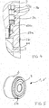
- the first rolling bodies 4 are guided laterally from the cover 5b by means of a second shoulder 50a, wherein the second shoulder 50a is chamfered in the direction of the first shoulder 50b (compare angle ⁇ in FIG FIG. 4 ).
- FIG. 3 shows a longitudinal section through a second support roller 1 '. Same reference numerals as in FIG. 1 or 2 identify similar elements. In contrast to FIGS. 1 and 2 Here are two rows 9a, 9b of second rolling elements 7 available. Instead of a cage 12a, 12b, two cages may be provided here in each case.
- FIG. 4 shows the area Z FIG. 3 in an enlarged view.
- the same reference numerals as in FIG. 3 designate the same elements.
- the first paragraph 50b on the cover 5b can be seen, on which the second rolling elements 7 or here of the second rolling elements 7 leading cage 12b, start. Furthermore, it can be seen that the first rolling elements 4 laterally from the lid 5b by means of the second paragraph 50a are guided, wherein the second shoulder 50a is tapered in the direction of the first paragraph 50b.
- the angle ⁇ is in particular in the range of 45 °.
- FIG. 5 shows a three-dimensional view of a support roller 1, 1 'with the outer ring 2, the inner ring 3 and a cover 5b.
Landscapes
- Engineering & Computer Science (AREA)
- General Engineering & Computer Science (AREA)
- Mechanical Engineering (AREA)
- Rolling Contact Bearings (AREA)
Abstract
Description
- Die Erfindung betrifft eine Stützrolle, insbesondere eine Laufrolle oder Kurvenrolle, mit einem Außenring, einem Innenring und zwischen dem Außenring und dem Innenring auf Laufbahnen abrollbaren ersten Wälzkörpern, die in mindestens zwei Reihen nebeneinander angeordnet sind.
- Eine derartige Stützrolle ist aus der
DE 10201321332 A1 bekannt. Die Stützrolle ist als Radiallager ausgeführt. - Die bekannte Stützrolle ist bei hohen radialen und gleichzeitig axialen Belastungen stark beansprucht. Solche Axialkräfte erzeugen ein Kippmoment, welches durch das Radiallager aufgenommen werden muss. Die Tragfähigkeit der Stützrolle ist in solchen Belastungsfällen daher eingeschränkt. Weiterhin gelangen je nach Anwendungsort der Stützrolle Verunreinigungen in das Lager, die zu weiteren Belastungen und in Folge Verschleiß führen.
- Es ist daher Aufgabe der Erfindung, die Belastbarkeit und Einsatzdauer einer Stützrolle zu erhöhen.
- Die Aufgabe wird gelöst durch eine Stützrolle gemäß Patentanspruch 1. Demnach ist die Stützrolle mit einem Außenring, einem Innenring und zwischen dem Außenring und dem Innenring auf Laufbahnen abrollbaren ersten Wälzkörpern gekennzeichnet, die in mindestens zwei Reihen nebeneinander angeordnet sind, wobei weiterhin zwei Deckel vorhanden sind, wobei jeweils einer der Deckel an einer Stirnseite des Außenrings angeordnet ist, wobei weiterhin zwischen dem Außenring und jedem der Deckel abrollbare zweite Wälzkörper vorhanden sind, die in mindestens einer Reihe angeordnet sind. Die Deckel sind weiterhin klemmend am Außenring oder Innenring befestigt. Dabei sind die Deckel zum Innenring zentriert, sodass alle Komponenten des Lagers korrekt zueinander positioniert sind. Dabei kann definiert die Lagerluft des Stützlagers in der jeweiligen Einbausituation eingestellt werden.
- Dadurch, dass die Deckel nicht verschraubt sind, ist die Tragfähigkeit des Stützlagers verbessert.
- Dabei ist ein Deckel so klemmend entweder am Außenring oder Innenring befestigt, dass keine Kraftübertragung vom Innenring zum Außenring über den Deckel erfolgt. Um eine solche Klemmung eines Deckels nur am Innenring oder Außenring zu realisieren, überdeckt insbesondere ein Deckel die Stirnseiten des Innenrings oder des Außenrings und erstreckt sich zudem bevorzugt in einen Raum zur Aufnahme der ersten Wälzkörper und zweiten Wälzkörper zwischen Innenring und Außenring hinein.
- Die erfindungsgemäße Stützrolle umfasst demnach ein Radiallager und ein Axiallager und kann Kippmomente optimal aufnehmen. Somit sind eine höhere Belastbarkeit und eine Verlängerung der Einsatzdauer der Stützrolle gegeben.
Vorteilhafte Ausgestaltungen der erfindungsgemäßen Stützrolle sind nachfolgend angegeben. - So ist es besonders bevorzugt, wenn die Deckel eine Seitenführung für die ersten Wälzkörper ausbilden. Dabei kann definiert die Lagerluft des Stützlagers in der jeweiligen Einbausituation eingestellt werden.
- Die Deckel sind insbesondere einen Raum zwischen dem Außenring und dem Innenring begrenzend ausgebildet. Dadurch lässt sich der Eintritt von Wasser und Verunreinigungen in das Stützlager verringern und ein Verschleiß des Lagers minimieren.
- Bevorzugt ist an jedem der Deckel mindestens eine erste Dichtungsanordnung vorhanden, die zum Außenring hin abdichtend ausgebildet ist. Die mindestens eine erste Dichtungsanordnung ist dabei vorzugsweise radial an jedem der Deckel vorhanden. Durch die mindestens eine erste Dichtungsanordnung lässt sich ein Eintritt von Wasser und Verunreinigungen in das Lager und damit der Verschleiß weiter vermindern und die Betriebsdauer steigern.
- Die mindestens eine der Reihen an zweiten Wälzkörpern ist vorzugsweise durch mindestens einen Käfig geführt angeordnet. Dadurch wird die Positionierung der zweiten Wälzkörper insbesondere beim Zusammenbau des Lagers vereinfacht. Insbesondere ist dieser mindestens eine Käfig aus Messing ausgebildet.
- Die zweiten Wälzkörper sind insbesondere in zwei Reihen oder mehr angeordnet Dadurch lässt sich die Tragfähigkeit des Gesamtsystems, insbesondere der ersten Wälzkörper, weiter verbessern.
- Vorzugsweise sind die zweiten Wälzkörper über einen Absatz an jedem Deckel radial geführt.
- An jedem der Deckel ist bevorzugt eine zweite Dichtungsanordnung vorhanden, die zum Innenring hin abdichtend ausgebildet ist. Dadurch lässt sich ein Eintritt von Wasser und Verunreinigungen in das Lager und damit der Verschleiß nochmals vermindem und die Betriebsdauer steigern.
- Die Deckel, sind erfindungsgemäß nicht fest mit anderen Bauteilen der Stützrolle verbunden. So sind die Deckel weder verschraubt noch vernietet oder dergleichen. Die Stützrolle wird nach dem Einbau in eine Umgebungskonstruktion über die Deckel vorgespannt. Dazu sind die Deckel zur Einstellung einer definierten Lagerluft abgepasst.
- Zum leichteren Einbau der Stützrolle in eine Umgebungskonstruktion können die Deckel über eine Fixierung in Form von beispielsweise Haltebändern oder Klebestreifen mit den anderen Bauteilen der Stützrolle verbunden sein. Diese hilfsweise Fixierung wird am Einbauort aber entfernt.
- Die Deckel sind vorzugsweise lediglich klemmend am Innenring befestigt und bedecken eine Stirnseite des Innenrings. Alternativ ist eine klemmende Anordnung der Deckel am Außenring möglich.
In der späteren Einbausituation ist vorgesehen, dass die zweiten Wälzkörper unter leichter Vorspannung zwischen dem jeweiligen Deckel und dem Außenring bei definierter Lagerluft eingesetzt sind. Demgegenüber ist vorgesehen, dass die ersten Wälzkörper mit einer größeren Lagerluft betrieben werden als die zweiten Wälzkörper. Die ersten Wälzkörper sind vorzugsweise in vier Reihen nebeneinander angeordnet sind. Dadurch lässt sich die Belastbarkeit des Stützlagers weiter steigern. - Der Einsatz einer derartigen Stützrolle erfolgt insbesondere in der Transportindustrie oder der Schwerindustrie zum Bewegen schwerer Lasten, wobei große Radial- und Axialkräfte wirken. Insbesondere ist ein Einsatz der erfindungsgemäßen Stützrolle an Gabelstaplern, auf Schiffen, insbesondere auf Transport- und Arbeitsschiffen, oder in der Stahlindustrie bevorzugt. Auf einem Arbeitsschiff werden derartige Stützrollen beispielsweise eingesetzt, um Stahlträger zu verfahren oder um Türme drehbar zu lagern. In der Stahlindustrie kommen derartige Stützrollen in Richtmaschinen oder Kaltwalzwerken zum Einsatz.
- Die
Figuren 1 bis 5 zeigen beispielhaft mögliche Ausführungsformen der erfindungsgemäßen Stützrolle. So zeigt - FIGUR 1
- einen Längsschnitt durch eine erste Stützrolle;
- FIGUR 2
- einen Ausschnitt aus
Figur 1 im Bereich eines Deckels; - FIGUR 3
- einen Längsschnitt durch eine zweite Stützrolle; '
- FIGUR 4
- den Bereich Z aus
Figur 3 in vergrößerter Darstellung; - FIGUR 5
- eine dreidimensionale Ansicht einer Stützrolle.
-
Figur 1 zeigt einen Längsschnitt durch eine erste Stützrolle 1, wobei nur die obere Hälfte des Stützrolle 1 dargestellt ist. Die Stützrolle 1 weist einen Außenring 2, einen Innenring 3 und zwischen dem Außenring 2 und dem Innenring 3 erste Wälzkörper 4 auf. Die ersten Wälzkörper 4 sind auf Laufbahnen 2a, 3a abrollbar, wobei die Laufbahn 2a am Außenring 2 und die Laufbahn 3a am Innenring 3 angeordnet ist. Dabei sind die ersten Wälzkörper 4 hier in vier Reihen 8a, 8b, 8c, 8d nebeneinander angeordnet. Weiterhin sind zwei Deckel 5a, 5b vorhanden, wobei der Deckel 5a an einer Stirnseite 20 des Innenrings 3 und der Deckel 5b an der Stirnseite 21 des Innenrings 3 klemmend angeordnet ist. Weiterhin sind zwischen dem Außenring 2 und jedem der Deckel 5a, 5b abrollbare zweite Wälzkörper 7 vorhanden, die in einer Reihe 9a angeordnet sind. Die zweiten Wälzkörper 7 sind durch einen Käfig 12a, 12b, der hier aus Messing gebildet ist, geführt. Die Deckel 5a, 5b erstrecken sich in einen Raum 6 zwischen dem Außenring 2 und dem Innenring 3 und bilden eine Seitenführung für die ersten Wälzkörper 4 aus. Der jeweilige Käfig 12a, 12b läuft gegen einen ersten Absatz 50 b (vergleicheFigur 2 ) an jedem Deckel 5a, 5b an. Die Deckel 5a, 5b sind den Raum 6 zwischen dem Außenring 2 und dem Innenring 3 begrenzend ausgebildet. An jedem der Deckel 5a, 5b ist radial eine erste Dichtungsanordnung 10a, 10b vorhanden, die zum Außenring 2 hin abdichtend ausgebildet ist. Weiterhin ist an jedem der Deckel 5a, 5b eine zweite Dichtungsanordnung 11a, 11b vorhanden, die zum Innenring 3 hin abdichtend ausgebildet ist. Dabei sind die Deckel 5ä, 5b nicht mit dem Außenring 2 oder dem Innenring 3 verschraubt und auch nicht zwischen diesen verklemmt. Die Deckel 5a, 5b bilden dabei eine Zentrierung für den Innenring 3. Der Außenring 2, der Innenring 3 und die ersten Wälzkörper 4 bilden ein Radiallager. Der Außenring 2 bildet weiterhin zusammen mit den Deckeln 5a, 5b und den zweiten Wälzkörpern 7 zwei weitere Axiallager. -
Figur 2 zeigt einen Ausschnitt ausFigur 1 im Bereich des Deckels 5b. Gleiche Bezugszeichen wie inFigur 1 kennzeichnen gleiche Elemente. Allerdings ist hier die zweite Dichtungsanordnung 11b im Unterschied zuFigur 1 an den Stirnseiten 20, 21 und damit seitlich am Innenring 3 anliegend ausgeführt. In dieser Darstellung ist ein erster Absatz 50b am Deckel 5b angeordnet, an welchem die zweiten Wälzkörper 7 beziehungsweise hier der die zweiten Wälzkörper 7 führende Käfig 12b, anlaufen. Weiterhin ist zu erkennen, dass die ersten Wälzkörper 4 seitlich von dem Deckel 5b mittels eines zweiten Absatzes 50a geführt sind, wobei der zweite Absatz 50a in Richtung des ersten Absatzes 50b angeschrägt ist (vergleiche Winkel α inFigur 4 ). -
Figur 3 zeigt einen Längsschnitt durch eine zweite Stützrolle 1'. Gleiche Bezugszeichen wie inFigur 1 oder 2 kennzeichnen gleiche Elemente. Im Unterschied zuFigur 1 und 2 sind hier zwei Reihen 9a, 9b von zweiten Wälzkörpern 7 vorhanden. Anstelle von einem Käfig 12a, 12b können hier auch jeweils zwei Käfige vorgesehen sein. -
Figur 4 zeigt den Bereich Z ausFigur 3 in vergrößerter Darstellung. Gleiche Bezugszeichen wie in Figur -3 kennzeichnen gleiche Elemente. Der erste Absatz 50b am Deckel 5b ist erkennbar, an welchem die zweiten Wälzkörper 7 beziehungsweise hier der die zweiten Wälzkörper 7 führende Käfig 12b, anlaufen. Weiterhin ist zu erkennen, dass die ersten Wälzkörper 4 seitlich von dem Deckel 5b mittels des zweiten Absatzes 50a geführt sind, wobei der zweite Absatz 50a in Richtung des ersten Absatzes 50b angeschrägt ist. Der Winkel α liegt dabei insbesondere im Bereich von 45°. -
Figur 5 zeigt eine dreidimensionale Ansicht einer Stützrolle 1, 1' mit dem Außenring 2, dem Innenring 3 und einem Deckel 5b. -
- 1, 1'
- Stützrolle
- 2
- Außenring
- 2a
- Laufbahn
- 3
- Innenring
- 3a
- Laufbahn
- 4
- erste Wälzkörper
- 5a, 5b
- Deckel
- 6
- Raum
- 7
- zweite Wälzkörper
- 8a, 8b, 8c, 8d
- Reihe an ersten Wälzkörpern
- 9a, 9b
- Reihe an zweiten Wälzkörpern
- 10a, 10b
- erste Dichtungsanordnung
- 11a, 11b
- zweite Dichtungsanordnung
- 12a, 12b
- Käfig
- 20, 21
- Stirnseite
- 50b
- erster Absatz
- 50a
- zweiter Absatz
- α
- Winkel
Claims (10)
- Stützrolle (1, 1) mit einem Außenring (2), einem Innenring (3) und zwischen dem Außenring (2) und dem Innenring (3) auf Laufbahnen (2a, 3a) abrollbaren ersten Wälzkörpern (4), die in mindestens zwei Reihen (8a, 8b, 8c, 8d) nebeneinander angeordnet sind, wobei weiterhin zwei Deckel (5a, 5b)vorhanden sind, wobei jeweils einer der Deckel (5a, 5b) an einer Stirnseite (20, 21) des Außenrings (2) angeordnet ist, wobei weiterhin zwischen dem Außenring (2) und jedem der Deckel (5a, 5b) abrollbare zweite Wälzkörper (7) vorhanden sind, die in mindestens einer Reihe (9a, 9b) angeordnet sind, und wobei die Deckel (5a; 5b) lediglich klemmend am Außenring (2) oder am Innenring (3) befestigt sind.
- Stützrolle (1', 1) nach Anspruch 1, wobei die Deckel (5a, 5b) eine Seitenführung für die ersten Wälzkörper (4) ausbilden.
- Stützrolle (1, 1') nach einem der Ansprüche 1 oder 2, wobei die Deckel (5a, 5b) einen Raum (6) zwischen dem Außenring (2) und dem Innenring (3) begrenzend ausgebildet sind.
- Stützrolle (1, 1') nach einem der Ansprüche 1 bis 3, wobei an jedem der Deckel (5a, 5b) mindestens eine erste Dichtungsanordnung (10a, 10b) vorhanden ist, die zum Außenring (2) hin abdichtend ausgebildet ist.
- Stützrolle (1, 1') nach Anspruch 4, wobei die mindestens eine erste Dichtungsanordnung (10a, 10b) radial an jedem der Deckel (5a, 5b) vorhanden ist.
- Stützrolle (1, 1') nach einem der Ansprüche 1 bis 5, wobei die mindestens eine der Reihen (9a, 9b) an zweiten Wälzkörpern (7) durch mindestens einen Käfig (12, 12b) geführt angeordnet ist.
- Stützrolle (1, 1') nach einem der Ansprüche 1 bis 6, wobei an jedem der Deckel (5a, 5b) eine zweite Dichtungsanordnung (11a, 11b) vorhanden ist, die zum Innenring (3) hin abdichtend ausgebildet ist.
- Stützrolle (1, 1') nach einem der Ansprüche 1 bis 6, wobei die zweiten Wälzkörper (7) in zwei oder mehr Reihen (9a, 9b) angeordnet sind.
- Stützrolle (1, 1') nach einem der Ansprüche 1 bis 7, wobei die Deckel (5a, 5b) lediglich klemmend am Innenring (3) befestigt sind und eine Stirnseite (20, 21) des Innenrings (3) bedecken.
- Stützrolle (1, 1') nach einem der Ansprüche 1 bis 8, wobei die ersten Wälzkörper in vier Reihen (8a, 8b, 8c, 8d) nebeneinander angeordnet sind.
Applications Claiming Priority (2)
| Application Number | Priority Date | Filing Date | Title |
|---|---|---|---|
| DE102017011933 | 2017-12-21 | ||
| DE102018101870.3A DE102018101870B4 (de) | 2017-12-21 | 2018-01-29 | Stützlager |
Publications (2)
| Publication Number | Publication Date |
|---|---|
| EP3502500A1 true EP3502500A1 (de) | 2019-06-26 |
| EP3502500B1 EP3502500B1 (de) | 2021-02-24 |
Family
ID=64664004
Family Applications (1)
| Application Number | Title | Priority Date | Filing Date |
|---|---|---|---|
| EP18000948.2A Active EP3502500B1 (de) | 2017-12-21 | 2018-12-07 | Stützlager |
Country Status (1)
| Country | Link |
|---|---|
| EP (1) | EP3502500B1 (de) |
Cited By (2)
| Publication number | Priority date | Publication date | Assignee | Title |
|---|---|---|---|---|
| CN113202860A (zh) * | 2021-05-08 | 2021-08-03 | 洛阳新强联回转支承股份有限公司 | 一种带凸端面双列滚子的三排圆柱滚子风电主轴轴承 |
| RU233395U1 (ru) * | 2024-11-08 | 2025-04-17 | федеральное государственное бюджетное образовательное учреждение высшего образования "Российский государственный университет им. А.Н. Косыгина (Технологии. Дизайн. Искусство)" | Радиально-упорный подшипник |
Citations (3)
| Publication number | Priority date | Publication date | Assignee | Title |
|---|---|---|---|---|
| DE1859511U (de) * | 1962-06-15 | 1962-10-04 | Schmiedetechnik G M B H | Lagerung einer laufrolle fuer kettenfahrzeuge. |
| DE10061786A1 (de) * | 2000-12-12 | 2002-07-04 | Fag Aircraft Super Prec Bearin | Stützrollenlager als gedichtete Baueinheit |
| CN103133517A (zh) * | 2011-11-30 | 2013-06-05 | 洛阳百思特精密机械制造有限公司 | 一种组合平挡圈滚轮轴承 |
-
2018
- 2018-12-07 EP EP18000948.2A patent/EP3502500B1/de active Active
Patent Citations (3)
| Publication number | Priority date | Publication date | Assignee | Title |
|---|---|---|---|---|
| DE1859511U (de) * | 1962-06-15 | 1962-10-04 | Schmiedetechnik G M B H | Lagerung einer laufrolle fuer kettenfahrzeuge. |
| DE10061786A1 (de) * | 2000-12-12 | 2002-07-04 | Fag Aircraft Super Prec Bearin | Stützrollenlager als gedichtete Baueinheit |
| CN103133517A (zh) * | 2011-11-30 | 2013-06-05 | 洛阳百思特精密机械制造有限公司 | 一种组合平挡圈滚轮轴承 |
Cited By (2)
| Publication number | Priority date | Publication date | Assignee | Title |
|---|---|---|---|---|
| CN113202860A (zh) * | 2021-05-08 | 2021-08-03 | 洛阳新强联回转支承股份有限公司 | 一种带凸端面双列滚子的三排圆柱滚子风电主轴轴承 |
| RU233395U1 (ru) * | 2024-11-08 | 2025-04-17 | федеральное государственное бюджетное образовательное учреждение высшего образования "Российский государственный университет им. А.Н. Косыгина (Технологии. Дизайн. Искусство)" | Радиально-упорный подшипник |
Also Published As
| Publication number | Publication date |
|---|---|
| EP3502500B1 (de) | 2021-02-24 |
Similar Documents
| Publication | Publication Date | Title |
|---|---|---|
| EP2092204B1 (de) | Wälzlager, insbesondere mittenfreies grosswälzlager | |
| EP2561241B1 (de) | Dichtungsanordnung für wälzlager | |
| EP1426639B1 (de) | Verfahren zur Montage eines zweireihigen Kegelrollenlagers mit geteilten Lagerringen in einer Windkraftanlage | |
| EP2185814B1 (de) | Gelagerte hauptwelle für eine windkraftanlage | |
| WO2018189143A1 (de) | Lageranordnung zur lagerung eines rotorblatts einer windenergieanlage | |
| EP2097651A1 (de) | Rollenlager, insbesondere mittenfreies grosswälzlager | |
| EP3332134A1 (de) | Schrägrollenlager sowie verfahren und vorrichtung zu dessen montage | |
| EP3333439B1 (de) | Verfahren zum austausch eines gebrauchten lagers, insbesondere zum austausch eines grosslagers, wie das hauptlager einer windkraftanlage sowie lageranordnung | |
| DE102018201820A1 (de) | Grosswälzlager mit zumindest zwei Reihen von Wälzelementen | |
| EP3273077B1 (de) | Wälzlager mit montageflansch | |
| EP3502500B1 (de) | Stützlager | |
| DE102006028200A1 (de) | Winkeleinstellbares Wälzlager | |
| DE10112293C1 (de) | Großdrehlagerung | |
| DE102011007494B4 (de) | Konzept zum Bereitstellen einer Anlageschulter in einem zylinderförmigen Lagergehäuse | |
| DE102018101870B4 (de) | Stützlager | |
| DE102020000768A1 (de) | Lager mit einem flansch, der in einen der lagerringe gecrimpt ist, und dessen herstellungsverfahren | |
| EP1239172B1 (de) | Grossdrehlagerung mit Wälzkörpern | |
| EP2944836B1 (de) | Wälzlager | |
| DE202018103079U1 (de) | Wälzlager | |
| EP2901029B1 (de) | Lagerelement für zwei raumrichtungen | |
| DE102013225331A1 (de) | Lageranordnung mit Labyrinthdichtung | |
| DE102015207015A1 (de) | Lagerkäfig eines Rollenwälzlagers | |
| DE102020001930A1 (de) | Großlager | |
| DE20202463U1 (de) | Großdrehlagerung | |
| DE102020131335B4 (de) | Wälzlager |
Legal Events
| Date | Code | Title | Description |
|---|---|---|---|
| PUAI | Public reference made under article 153(3) epc to a published international application that has entered the european phase |
Free format text: ORIGINAL CODE: 0009012 |
|
| STAA | Information on the status of an ep patent application or granted ep patent |
Free format text: STATUS: THE APPLICATION HAS BEEN PUBLISHED |
|
| AK | Designated contracting states |
Kind code of ref document: A1 Designated state(s): AL AT BE BG CH CY CZ DE DK EE ES FI FR GB GR HR HU IE IS IT LI LT LU LV MC MK MT NL NO PL PT RO RS SE SI SK SM TR |
|
| AX | Request for extension of the european patent |
Extension state: BA ME |
|
| STAA | Information on the status of an ep patent application or granted ep patent |
Free format text: STATUS: REQUEST FOR EXAMINATION WAS MADE |
|
| 17P | Request for examination filed |
Effective date: 20200102 |
|
| RBV | Designated contracting states (corrected) |
Designated state(s): AL AT BE BG CH CY CZ DE DK EE ES FI FR GB GR HR HU IE IS IT LI LT LU LV MC MK MT NL NO PL PT RO RS SE SI SK SM TR |
|
| GRAP | Despatch of communication of intention to grant a patent |
Free format text: ORIGINAL CODE: EPIDOSNIGR1 |
|
| STAA | Information on the status of an ep patent application or granted ep patent |
Free format text: STATUS: GRANT OF PATENT IS INTENDED |
|
| INTG | Intention to grant announced |
Effective date: 20201105 |
|
| GRAS | Grant fee paid |
Free format text: ORIGINAL CODE: EPIDOSNIGR3 |
|
| GRAA | (expected) grant |
Free format text: ORIGINAL CODE: 0009210 |
|
| STAA | Information on the status of an ep patent application or granted ep patent |
Free format text: STATUS: THE PATENT HAS BEEN GRANTED |
|
| AK | Designated contracting states |
Kind code of ref document: B1 Designated state(s): AL AT BE BG CH CY CZ DE DK EE ES FI FR GB GR HR HU IE IS IT LI LT LU LV MC MK MT NL NO PL PT RO RS SE SI SK SM TR |
|
| REG | Reference to a national code |
Ref country code: CH Ref legal event code: EP |
|
| REG | Reference to a national code |
Ref country code: AT Ref legal event code: REF Ref document number: 1364807 Country of ref document: AT Kind code of ref document: T Effective date: 20210315 |
|
| REG | Reference to a national code |
Ref country code: IE Ref legal event code: FG4D Free format text: LANGUAGE OF EP DOCUMENT: GERMAN |
|
| REG | Reference to a national code |
Ref country code: DE Ref legal event code: R096 Ref document number: 502018003946 Country of ref document: DE |
|
| REG | Reference to a national code |
Ref country code: SE Ref legal event code: TRGR |
|
| REG | Reference to a national code |
Ref country code: NL Ref legal event code: FP |
|
| REG | Reference to a national code |
Ref country code: LT Ref legal event code: MG9D |
|
| PG25 | Lapsed in a contracting state [announced via postgrant information from national office to epo] |
Ref country code: PT Free format text: LAPSE BECAUSE OF FAILURE TO SUBMIT A TRANSLATION OF THE DESCRIPTION OR TO PAY THE FEE WITHIN THE PRESCRIBED TIME-LIMIT Effective date: 20210624 Ref country code: NO Free format text: LAPSE BECAUSE OF FAILURE TO SUBMIT A TRANSLATION OF THE DESCRIPTION OR TO PAY THE FEE WITHIN THE PRESCRIBED TIME-LIMIT Effective date: 20210524 Ref country code: GR Free format text: LAPSE BECAUSE OF FAILURE TO SUBMIT A TRANSLATION OF THE DESCRIPTION OR TO PAY THE FEE WITHIN THE PRESCRIBED TIME-LIMIT Effective date: 20210525 Ref country code: HR Free format text: LAPSE BECAUSE OF FAILURE TO SUBMIT A TRANSLATION OF THE DESCRIPTION OR TO PAY THE FEE WITHIN THE PRESCRIBED TIME-LIMIT Effective date: 20210224 Ref country code: FI Free format text: LAPSE BECAUSE OF FAILURE TO SUBMIT A TRANSLATION OF THE DESCRIPTION OR TO PAY THE FEE WITHIN THE PRESCRIBED TIME-LIMIT Effective date: 20210224 Ref country code: BG Free format text: LAPSE BECAUSE OF FAILURE TO SUBMIT A TRANSLATION OF THE DESCRIPTION OR TO PAY THE FEE WITHIN THE PRESCRIBED TIME-LIMIT Effective date: 20210524 Ref country code: LT Free format text: LAPSE BECAUSE OF FAILURE TO SUBMIT A TRANSLATION OF THE DESCRIPTION OR TO PAY THE FEE WITHIN THE PRESCRIBED TIME-LIMIT Effective date: 20210224 |
|
| PG25 | Lapsed in a contracting state [announced via postgrant information from national office to epo] |
Ref country code: RS Free format text: LAPSE BECAUSE OF FAILURE TO SUBMIT A TRANSLATION OF THE DESCRIPTION OR TO PAY THE FEE WITHIN THE PRESCRIBED TIME-LIMIT Effective date: 20210224 Ref country code: PL Free format text: LAPSE BECAUSE OF FAILURE TO SUBMIT A TRANSLATION OF THE DESCRIPTION OR TO PAY THE FEE WITHIN THE PRESCRIBED TIME-LIMIT Effective date: 20210224 Ref country code: LV Free format text: LAPSE BECAUSE OF FAILURE TO SUBMIT A TRANSLATION OF THE DESCRIPTION OR TO PAY THE FEE WITHIN THE PRESCRIBED TIME-LIMIT Effective date: 20210224 |
|
| PG25 | Lapsed in a contracting state [announced via postgrant information from national office to epo] |
Ref country code: IS Free format text: LAPSE BECAUSE OF FAILURE TO SUBMIT A TRANSLATION OF THE DESCRIPTION OR TO PAY THE FEE WITHIN THE PRESCRIBED TIME-LIMIT Effective date: 20210624 |
|
| PG25 | Lapsed in a contracting state [announced via postgrant information from national office to epo] |
Ref country code: SM Free format text: LAPSE BECAUSE OF FAILURE TO SUBMIT A TRANSLATION OF THE DESCRIPTION OR TO PAY THE FEE WITHIN THE PRESCRIBED TIME-LIMIT Effective date: 20210224 Ref country code: CZ Free format text: LAPSE BECAUSE OF FAILURE TO SUBMIT A TRANSLATION OF THE DESCRIPTION OR TO PAY THE FEE WITHIN THE PRESCRIBED TIME-LIMIT Effective date: 20210224 Ref country code: EE Free format text: LAPSE BECAUSE OF FAILURE TO SUBMIT A TRANSLATION OF THE DESCRIPTION OR TO PAY THE FEE WITHIN THE PRESCRIBED TIME-LIMIT Effective date: 20210224 |
|
| REG | Reference to a national code |
Ref country code: DE Ref legal event code: R097 Ref document number: 502018003946 Country of ref document: DE |
|
| PG25 | Lapsed in a contracting state [announced via postgrant information from national office to epo] |
Ref country code: DK Free format text: LAPSE BECAUSE OF FAILURE TO SUBMIT A TRANSLATION OF THE DESCRIPTION OR TO PAY THE FEE WITHIN THE PRESCRIBED TIME-LIMIT Effective date: 20210224 Ref country code: SK Free format text: LAPSE BECAUSE OF FAILURE TO SUBMIT A TRANSLATION OF THE DESCRIPTION OR TO PAY THE FEE WITHIN THE PRESCRIBED TIME-LIMIT Effective date: 20210224 Ref country code: RO Free format text: LAPSE BECAUSE OF FAILURE TO SUBMIT A TRANSLATION OF THE DESCRIPTION OR TO PAY THE FEE WITHIN THE PRESCRIBED TIME-LIMIT Effective date: 20210224 |
|
| PLBE | No opposition filed within time limit |
Free format text: ORIGINAL CODE: 0009261 |
|
| STAA | Information on the status of an ep patent application or granted ep patent |
Free format text: STATUS: NO OPPOSITION FILED WITHIN TIME LIMIT |
|
| PG25 | Lapsed in a contracting state [announced via postgrant information from national office to epo] |
Ref country code: AL Free format text: LAPSE BECAUSE OF FAILURE TO SUBMIT A TRANSLATION OF THE DESCRIPTION OR TO PAY THE FEE WITHIN THE PRESCRIBED TIME-LIMIT Effective date: 20210224 Ref country code: ES Free format text: LAPSE BECAUSE OF FAILURE TO SUBMIT A TRANSLATION OF THE DESCRIPTION OR TO PAY THE FEE WITHIN THE PRESCRIBED TIME-LIMIT Effective date: 20210224 |
|
| 26N | No opposition filed |
Effective date: 20211125 |
|
| PG25 | Lapsed in a contracting state [announced via postgrant information from national office to epo] |
Ref country code: SI Free format text: LAPSE BECAUSE OF FAILURE TO SUBMIT A TRANSLATION OF THE DESCRIPTION OR TO PAY THE FEE WITHIN THE PRESCRIBED TIME-LIMIT Effective date: 20210224 |
|
| PG25 | Lapsed in a contracting state [announced via postgrant information from national office to epo] |
Ref country code: IS Free format text: LAPSE BECAUSE OF FAILURE TO SUBMIT A TRANSLATION OF THE DESCRIPTION OR TO PAY THE FEE WITHIN THE PRESCRIBED TIME-LIMIT Effective date: 20210624 |
|
| PG25 | Lapsed in a contracting state [announced via postgrant information from national office to epo] |
Ref country code: MC Free format text: LAPSE BECAUSE OF FAILURE TO SUBMIT A TRANSLATION OF THE DESCRIPTION OR TO PAY THE FEE WITHIN THE PRESCRIBED TIME-LIMIT Effective date: 20210224 |
|
| REG | Reference to a national code |
Ref country code: CH Ref legal event code: PL |
|
| REG | Reference to a national code |
Ref country code: BE Ref legal event code: MM Effective date: 20211231 |
|
| PG25 | Lapsed in a contracting state [announced via postgrant information from national office to epo] |
Ref country code: LU Free format text: LAPSE BECAUSE OF NON-PAYMENT OF DUE FEES Effective date: 20211207 Ref country code: IE Free format text: LAPSE BECAUSE OF NON-PAYMENT OF DUE FEES Effective date: 20211207 |
|
| PG25 | Lapsed in a contracting state [announced via postgrant information from national office to epo] |
Ref country code: BE Free format text: LAPSE BECAUSE OF NON-PAYMENT OF DUE FEES Effective date: 20211231 |
|
| PG25 | Lapsed in a contracting state [announced via postgrant information from national office to epo] |
Ref country code: LI Free format text: LAPSE BECAUSE OF NON-PAYMENT OF DUE FEES Effective date: 20211231 Ref country code: CH Free format text: LAPSE BECAUSE OF NON-PAYMENT OF DUE FEES Effective date: 20211231 |
|
| P01 | Opt-out of the competence of the unified patent court (upc) registered |
Effective date: 20230523 |
|
| PG25 | Lapsed in a contracting state [announced via postgrant information from national office to epo] |
Ref country code: CY Free format text: LAPSE BECAUSE OF FAILURE TO SUBMIT A TRANSLATION OF THE DESCRIPTION OR TO PAY THE FEE WITHIN THE PRESCRIBED TIME-LIMIT Effective date: 20210224 |
|
| PG25 | Lapsed in a contracting state [announced via postgrant information from national office to epo] |
Ref country code: HU Free format text: LAPSE BECAUSE OF FAILURE TO SUBMIT A TRANSLATION OF THE DESCRIPTION OR TO PAY THE FEE WITHIN THE PRESCRIBED TIME-LIMIT; INVALID AB INITIO Effective date: 20181207 |
|
| GBPC | Gb: european patent ceased through non-payment of renewal fee |
Effective date: 20221207 |
|
| PG25 | Lapsed in a contracting state [announced via postgrant information from national office to epo] |
Ref country code: GB Free format text: LAPSE BECAUSE OF NON-PAYMENT OF DUE FEES Effective date: 20221207 |
|
| PG25 | Lapsed in a contracting state [announced via postgrant information from national office to epo] |
Ref country code: MK Free format text: LAPSE BECAUSE OF FAILURE TO SUBMIT A TRANSLATION OF THE DESCRIPTION OR TO PAY THE FEE WITHIN THE PRESCRIBED TIME-LIMIT Effective date: 20210224 |
|
| PG25 | Lapsed in a contracting state [announced via postgrant information from national office to epo] |
Ref country code: TR Free format text: LAPSE BECAUSE OF FAILURE TO SUBMIT A TRANSLATION OF THE DESCRIPTION OR TO PAY THE FEE WITHIN THE PRESCRIBED TIME-LIMIT Effective date: 20210224 |
|
| PG25 | Lapsed in a contracting state [announced via postgrant information from national office to epo] |
Ref country code: MT Free format text: LAPSE BECAUSE OF FAILURE TO SUBMIT A TRANSLATION OF THE DESCRIPTION OR TO PAY THE FEE WITHIN THE PRESCRIBED TIME-LIMIT Effective date: 20210224 |
|
| REG | Reference to a national code |
Ref country code: AT Ref legal event code: MM01 Ref document number: 1364807 Country of ref document: AT Kind code of ref document: T Effective date: 20231207 |
|
| PG25 | Lapsed in a contracting state [announced via postgrant information from national office to epo] |
Ref country code: AT Free format text: LAPSE BECAUSE OF NON-PAYMENT OF DUE FEES Effective date: 20231207 |
|
| PGFP | Annual fee paid to national office [announced via postgrant information from national office to epo] |
Ref country code: IT Payment date: 20251223 Year of fee payment: 8 |
|
| PGFP | Annual fee paid to national office [announced via postgrant information from national office to epo] |
Ref country code: FR Payment date: 20251229 Year of fee payment: 8 Ref country code: NL Payment date: 20251219 Year of fee payment: 8 |
|
| PGFP | Annual fee paid to national office [announced via postgrant information from national office to epo] |
Ref country code: SE Payment date: 20251219 Year of fee payment: 8 |
|
| PGFP | Annual fee paid to national office [announced via postgrant information from national office to epo] |
Ref country code: DE Payment date: 20260101 Year of fee payment: 8 |
|
| PGFP | Annual fee paid to national office [announced via postgrant information from national office to epo] |
Ref country code: AT Payment date: 20260410 Year of fee payment: 5 |