EP3502066A1 - Verfahren zur herstellung von glasrohren - Google Patents
Verfahren zur herstellung von glasrohren Download PDFInfo
- Publication number
- EP3502066A1 EP3502066A1 EP17841338.1A EP17841338A EP3502066A1 EP 3502066 A1 EP3502066 A1 EP 3502066A1 EP 17841338 A EP17841338 A EP 17841338A EP 3502066 A1 EP3502066 A1 EP 3502066A1
- Authority
- EP
- European Patent Office
- Prior art keywords
- glass tube
- hole
- burner
- tube
- manufacturing
- Prior art date
- Legal status (The legal status is an assumption and is not a legal conclusion. Google has not performed a legal analysis and makes no representation as to the accuracy of the status listed.)
- Granted
Links
- 239000011521 glass Substances 0.000 title claims abstract description 173
- 238000004519 manufacturing process Methods 0.000 title claims abstract description 32
- 238000000034 method Methods 0.000 claims description 28
- 239000007789 gas Substances 0.000 claims description 17
- QVGXLLKOCUKJST-UHFFFAOYSA-N atomic oxygen Chemical compound [O] QVGXLLKOCUKJST-UHFFFAOYSA-N 0.000 claims description 13
- 239000001301 oxygen Substances 0.000 claims description 13
- 229910052760 oxygen Inorganic materials 0.000 claims description 13
- 239000000203 mixture Substances 0.000 claims description 12
- 239000001257 hydrogen Substances 0.000 claims description 11
- 229910052739 hydrogen Inorganic materials 0.000 claims description 11
- UFHFLCQGNIYNRP-UHFFFAOYSA-N Hydrogen Chemical compound [H][H] UFHFLCQGNIYNRP-UHFFFAOYSA-N 0.000 claims description 10
- 230000015572 biosynthetic process Effects 0.000 claims description 10
- 239000000446 fuel Substances 0.000 claims description 3
- 239000002737 fuel gas Substances 0.000 description 32
- 239000012535 impurity Substances 0.000 description 12
- 230000003749 cleanliness Effects 0.000 description 9
- 239000003949 liquefied natural gas Substances 0.000 description 4
- 239000000126 substance Substances 0.000 description 4
- 238000010586 diagram Methods 0.000 description 3
- 238000009423 ventilation Methods 0.000 description 3
- 238000002485 combustion reaction Methods 0.000 description 2
- 239000003517 fume Substances 0.000 description 2
- 238000010438 heat treatment Methods 0.000 description 2
- 230000001965 increasing effect Effects 0.000 description 2
- 239000003915 liquefied petroleum gas Substances 0.000 description 2
- 239000003708 ampul Substances 0.000 description 1
- 238000007664 blowing Methods 0.000 description 1
- 239000005388 borosilicate glass Substances 0.000 description 1
- 230000007423 decrease Effects 0.000 description 1
- 238000003280 down draw process Methods 0.000 description 1
- 230000000694 effects Effects 0.000 description 1
- 230000002708 enhancing effect Effects 0.000 description 1
- 150000002431 hydrogen Chemical class 0.000 description 1
- 239000011261 inert gas Substances 0.000 description 1
- 239000006060 molten glass Substances 0.000 description 1
- 238000007789 sealing Methods 0.000 description 1
Images

Classifications
-
- C—CHEMISTRY; METALLURGY
- C03—GLASS; MINERAL OR SLAG WOOL
- C03B—MANUFACTURE, SHAPING, OR SUPPLEMENTARY PROCESSES
- C03B23/00—Re-forming shaped glass
- C03B23/18—Re-forming and sealing ampoules
-
- B—PERFORMING OPERATIONS; TRANSPORTING
- B08—CLEANING
- B08B—CLEANING IN GENERAL; PREVENTION OF FOULING IN GENERAL
- B08B5/00—Cleaning by methods involving the use of air flow or gas flow
- B08B5/02—Cleaning by the force of jets, e.g. blowing-out cavities
-
- B—PERFORMING OPERATIONS; TRANSPORTING
- B08—CLEANING
- B08B—CLEANING IN GENERAL; PREVENTION OF FOULING IN GENERAL
- B08B9/00—Cleaning hollow articles by methods or apparatus specially adapted thereto
- B08B9/02—Cleaning pipes or tubes or systems of pipes or tubes
- B08B9/027—Cleaning the internal surfaces; Removal of blockages
- B08B9/032—Cleaning the internal surfaces; Removal of blockages by the mechanical action of a moving fluid, e.g. by flushing
- B08B9/0321—Cleaning the internal surfaces; Removal of blockages by the mechanical action of a moving fluid, e.g. by flushing using pressurised, pulsating or purging fluid
-
- C—CHEMISTRY; METALLURGY
- C03—GLASS; MINERAL OR SLAG WOOL
- C03B—MANUFACTURE, SHAPING, OR SUPPLEMENTARY PROCESSES
- C03B23/00—Re-forming shaped glass
- C03B23/04—Re-forming tubes or rods
- C03B23/043—Heating devices specially adapted for re-forming tubes or rods in general, e.g. burners
-
- C—CHEMISTRY; METALLURGY
- C03—GLASS; MINERAL OR SLAG WOOL
- C03B—MANUFACTURE, SHAPING, OR SUPPLEMENTARY PROCESSES
- C03B23/00—Re-forming shaped glass
- C03B23/04—Re-forming tubes or rods
- C03B23/057—Re-forming tubes or rods by fusing, e.g. for flame sealing
-
- C—CHEMISTRY; METALLURGY
- C03—GLASS; MINERAL OR SLAG WOOL
- C03B—MANUFACTURE, SHAPING, OR SUPPLEMENTARY PROCESSES
- C03B23/00—Re-forming shaped glass
- C03B23/04—Re-forming tubes or rods
- C03B23/09—Reshaping the ends, e.g. as grooves, threads or mouths
- C03B23/099—Reshaping the ends, e.g. as grooves, threads or mouths by fusing, e.g. flame sealing
-
- C—CHEMISTRY; METALLURGY
- C03—GLASS; MINERAL OR SLAG WOOL
- C03B—MANUFACTURE, SHAPING, OR SUPPLEMENTARY PROCESSES
- C03B33/00—Severing cooled glass
- C03B33/06—Cutting or splitting glass tubes, rods, or hollow products
-
- B—PERFORMING OPERATIONS; TRANSPORTING
- B08—CLEANING
- B08B—CLEANING IN GENERAL; PREVENTION OF FOULING IN GENERAL
- B08B2209/00—Details of machines or methods for cleaning hollow articles
- B08B2209/02—Details of apparatuses or methods for cleaning pipes or tubes
- B08B2209/027—Details of apparatuses or methods for cleaning pipes or tubes for cleaning the internal surfaces
- B08B2209/032—Details of apparatuses or methods for cleaning pipes or tubes for cleaning the internal surfaces by the mechanical action of a moving fluid
-
- Y—GENERAL TAGGING OF NEW TECHNOLOGICAL DEVELOPMENTS; GENERAL TAGGING OF CROSS-SECTIONAL TECHNOLOGIES SPANNING OVER SEVERAL SECTIONS OF THE IPC; TECHNICAL SUBJECTS COVERED BY FORMER USPC CROSS-REFERENCE ART COLLECTIONS [XRACs] AND DIGESTS
- Y02—TECHNOLOGIES OR APPLICATIONS FOR MITIGATION OR ADAPTATION AGAINST CLIMATE CHANGE
- Y02P—CLIMATE CHANGE MITIGATION TECHNOLOGIES IN THE PRODUCTION OR PROCESSING OF GOODS
- Y02P40/00—Technologies relating to the processing of minerals
- Y02P40/50—Glass production, e.g. reusing waste heat during processing or shaping
- Y02P40/57—Improving the yield, e-g- reduction of reject rates
Definitions
- the present invention relates to a method for manufacturing a glass tube.
- a glass tube is used that includes a sealed end and a through hole formed in the tube wall near the sealed end (patent document 1).
- a glass tube is manufactured by sealing one open end of a glass tube and forming a through hole in the tube wall near the end.
- Patent Document 1 Japanese Laid-Open Patent Publication No. 2004-010475
- the present invention is made in view of such circumstances, and its objective is to provide a method for manufacturing a glass tube that enhances the cleanliness of the inside of the glass tube, which includes a sealed end and a through hole formed in the tube wall near the sealed end.
- a method for manufacturing a glass tube that solves the above problem includes the step of forming a through hole in a tube wall of a glass tube with two ends including a first end and a second end, each having an opening, near the first end.
- the method further includes the step of forming a sealed portion by performing thermal processing on a predetermined portion of the glass tube between the first end and the through hole after the formation of the through hole.
- the sealed portion is formed after the formation of the through hole so that impurities produced when forming the through hole can be discharged from the opening in the first end of the glass tube.
- the formation of the through hole be performed while sending air into the glass tube from the opening in the second end of the glass tube toward the opening in the first end of the glass tube.
- the impurities produced when forming the through hole can be forced out of the opening in the first end of the glass tube.
- the formation of the through hole be performed with a burner in a state in which the glass tube is supported at a position where an axis of the glass tube is horizontal or a position where the first end of the glass tube is located at an upper side.
- the formation of the through hole be performed with a burner that uses a gas mixture of oxygen and hydrogen as fuel, and that the burner be arranged so that a distance between a nozzle edge of the burner when being used and the glass tube is greater than or equal to 3 mm.
- the usage of the gas mixture of oxygen and hydrogen as the fuel for the burner shortens the time required for forming the through hole in the glass tube.
- the through hole is formed with the burner that is spaced apart from the glass tube so that the distance between the nozzle edge of the burner and the glass tube is greater than or equal to 3 mm. This reduces the impurities (volatile substances) that are produced during the formation of the through hole and collect on the nozzle edge of the burner.
- the glass tube be used as a medicinal container.
- a medicinal container requires high cleanliness.
- the use of the glass tube is preferred when manufacturing a medicinal container.
- the present invention succeeds in enhancing the cleanliness of the inside of a glass tube that includes a sealed end and a through hole arranged in a tube wall near the sealed end.
- a glass tube 11 that is the subject of manufacture includes a tube portion 12 including two ends.
- the glass tube 11 includes a sealed portion 13 that is located at one end of the tube portion 12 and an opening 14 that is located at the other end of the tube portion 12.
- a through hole 15 is formed in the tube wall near the sealed portion 13 of the tube portion 12.
- the glass tube 11 is manufactured from a glass tube 16 that includes two open ends.
- the method for manufacturing the glass tube 11 includes a through hole forming step of forming the through hole 15 in the glass tube 16, and a sealed portion forming step of forming the sealed portion 13 in the glass tube 16.
- the through hole forming step is performed on the glass tube 16 that includes an opening 17 in a first end 16a and an opening 18 in a second end 16b.
- the glass tube 16 may be a straight tube that is formed from molten glass through the Danner process or the down-draw process (Vello process) and cut into a predetermined length.
- the through hole 15 is formed in the tube wall of the glass tube 16 near the first end 16a.
- the through hole 15 is formed with a burner 19.
- the burner 19 includes a fuel gas nozzle 20 that emits fuel gas FG toward the glass tube 16.
- the through hole 15 be formed in a state in which the glass tube 16 is supported at a position where the axis of the glass tube 16 is horizontal or a position where the first end 16a of the glass tube 16 is located at an upper side.
- a support 21 is used to support the glass tube 16 at a position where the axis of the glass tube 16 is horizontal.
- the burner 19 is arranged to direct a flame from vertically below the axis of the glass tube 16.
- the combustion performed by the burner 19 may be of a premixing type that mixes the fuel gas FG and air prior to combustion or a diffusion-mixing type (nozzle mixing type) in which the fuel gas FG and air are diffused and mixed when burned.
- the premixed type may be of a total premixing type in which the amount of premixed air is greater than the theoretical amount of air or a partial premixing type in which the amount of premixed air is less than the theoretical amount of air.
- a mixture of a flammable gas and a supporting gas is used as the fuel gas FG in the through hole forming step.
- the flammable gas include hydrogen, liquefied petroleum gas (LPG), and liquefied natural gas (LNG).
- An example of the supporting gas is oxygen.
- the fuel gas FG is a gas mixture of oxygen and hydrogen.
- the high flame temperature allows the through hole 15 to be formed in a relatively short time even when a nozzle edge 20a of the fuel gas nozzle 20 of the burner 19 is moved away from the glass tube 16.
- the gas mixture has a volume ratio of hydrogen to oxygen (that is, volume of hydrogen/volume of oxygen) that is greater than or equal to 1 and less than or equal to 3.
- a distance D between the nozzle edge 20a of the fuel gas nozzle 20 of the burner 19 and the glass tube 16 is preferably greater than or equal to 3 mm, further preferably greater than or equal to 5 mm, and even further preferably greater than or equal to 7 mm.
- the distance D increases, impurities such as fumes produced when forming the through hole 15 are less likely to collect on the nozzle edge 20a.
- the distance D is preferably less than or equal to 15 mm, and further preferably less than or equal to 12 mm. As the distance D decreases, the time required for forming the through hole 15 in the glass tube 16 becomes shorter.
- the distance D is preferably in a range greater than or equal to 3 mm and less than or equal to 15 mm, further preferably greater than or equal to 5 mm and less than or equal to 15 mm, even further preferably greater than or equal to 7 mm and less than or equal to 12 mm.
- a gas mixture of oxygen and hydrogen was used as the fuel gas FG for forming the through hole 15 in the glass tube 16.
- the distance D between the nozzle edge 20a of the fuel gas nozzle 20 and the glass tube 16 was set to 3.0 mm, 5.0 mm, 7.0 mm, 10.0 mm, 12.0 mm, or 15.0 mm.
- time T was measured from when the flame was directed toward the glass tube 16 to when the through hole 15 was formed.
- the fuel gas FG gas mixture
- the fuel gas FG having the inner diameter of 0.4 mm was used.
- the glass tube 16 had the outer diameter of 16 mm and the tube wall thickness of 1.0 mm.
- a gas mixture of LNG and oxygen was used as the fuel gas FG for forming the through hole 15 in the glass tube 16.
- the distance D between the nozzle edge 20a of the fuel gas nozzle 20 and the glass tube 16 was set to 3.0 mm.
- time T was measured from when the flame was directed toward the glass tube 16 to when the through hole 15 was formed.
- the fuel gas FG gas mixture
- the fuel gas nozzle 20 having the inner diameter of 1.0 mm was used.
- the glass tube 16 had the outer diameter of 16 mm and the tube wall thickness of 1.0 mm.
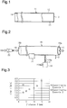
- Fig. 3 shows the relationship of the distance D and the time T, which is from when the flame was directed toward the glass tube 16 to when the through hole 15 was formed, in experimental example 1 and experimental example 2.
- the through hole 15 was formed in a shorter time than experimental example 2 even when the distance D was increased.
- Fig. 4 shows the relationship of the distance D and the diameter of the through hole 15 (hole diameter HD) formed in the glass tube 16 in experimental example 1. According to the result of experimental example 1, the hole diameter HD of the through hole 15 formed in the glass tube 16 can be changed when changing the distance D.
- the flow rate of the fuel gas FG emitted from the fuel gas nozzle 20 can be adjusted, for example, in accordance with the inner diameter of the fuel gas nozzle 20 (nozzle diameter).
- the flow rate of the fuel gas FG emitted from the fuel gas nozzle 20 is preferably greater than or equal to 1.5 L/min, further preferably greater than or equal to 1.7 L/min, and even further preferably greater than or equal to 1.9 L/min.
- the time required for forming the through hole 15 in the glass tube 16 can be shortened by increasing the flow rate of the fuel gas FG.
- the flow rate of the fuel gas FG emitted from the fuel gas nozzle 20 is preferably less than or equal to 3.0 L/min, and further preferably less than or equal to 2.5 L/min in order to prevent the tube wall of the glass tube 16 opposing the through hole 15 from being inadvertently melted after the through hole 15 is formed in the glass tube 16.
- the fuel gas nozzle 20 used in the through hole forming step has an inner diameter (nozzle diameter) that is greater than or equal to 0.2 mm. As the inner diameter of the fuel gas nozzle 20 increases, the inner diameter of the through hole 15 in the glass tube 16 increases. Preferably, the inner diameter of the fuel gas nozzle 20 (nozzle diameter) is less than or equal to 1.0 mm in order to prevent the inner diameter of the through hole 15 in the glass tube 16 from being excessively large.
- the through hole 15 be formed while air is blown into the glass tube 16 from the opening 18 in the second end 16b of the glass tube 16 toward the opening 17 in the first end 16a of the glass tube 16.
- a blast nozzle 22 is used to send ventilation gas VG into the glass tube 16 from the outside of the glass tube 16 toward the opening 18 in the second end 16b of the glass tube 16.
- the blast nozzle 22 may be inserted into the glass tube 16 through the opening 18 in the second end 16b of the glass tube 16.
- ventilation gas VG is air or an inert gas.
- the sealed portion 13 is formed by thermally processing a predetermined portion of the glass tube 16 between the first end 16a and the through hole 15 subsequent to the through hole forming step. More specifically, in the sealed portion forming step, the sealed portion 13 is formed by heating a portion of the glass tube 16 located between the first end 16a of the glass tube 16 and the through hole 15 in a circumferential direction while rotating the glass tube 16. Then, an external force is applied to the glass tube 16 so as to separate portions sandwiching the heated portion of the glass tube 16 from each other.
- the sealed portion forming step can be performed while moving the glass tube 16. More specifically, first, the glass tube 16 is arranged so that the axis of the glass tube 16 is orthogonal to a longitudinal direction of a flame 23a of the linear burner 23. Next, the glass tube 16 is moved in the longitudinal direction of the flame of the linear burner 23 while rotating the glass tube 16. In this case, an external force is applied to the glass tube 16 so that the portions sandwiching the heated portion of the glass tube 16 are separated from each other. This deforms the heated portion of the glass tube 16 to close and form the sealed portion 13.
- the sealed portion 13 may be formed by heating the glass tube 16 at a fixed position while rotating the glass tube 16 and applying an external force to the glass tube 16.
- the glass tube 11 (glass item including tube portion 12, sealed portion 13, opening 14, and through hole 15) manufactured through the through hole forming step and the sealed portion forming step is used to manufacture a glass container.
- a glass container is obtained through a manufacturing method including a step in which the glass tube 11 is arranged so that the sealed portion 13 is located at an upper side, and a portion located at a predetermined length separated from the opening 14 of the glass tube 11 is heated and cut.
- the through hole 15 of the glass tube 11 functions as a ventilation hole that adjusts the pressure and temperature in the tube portion 12 of the glass tube 11.
- the glass tube 11 is suitable for use when manufacturing a glass container that requires a relatively high cleanliness.
- the glass tube 11 is used, for example, to manufacture a medicinal container or a food container.
- the glass tube 11 is suitable for use when manufacturing a medicinal container.
- the medicinal containers include a syringe, a vial, and an ampoule.
- the glass tube 11 used to manufacture a medicinal container is, for example, made of a borosilicate glass.
- the outer diameter of the tube portion 12 is, for example, in a range greater than or equal to 5 mm and less than or equal to 75 mm.
- the tube wall thickness of the tube portion 12 (tube wall thickness of glass tube 16) is, for example, in a range greater than or equal to 0.3 mm and less than or equal to 3.0 mm.
Applications Claiming Priority (2)
| Application Number | Priority Date | Filing Date | Title |
|---|---|---|---|
| JP2016159658A JP6801289B2 (ja) | 2016-08-16 | 2016-08-16 | ガラス管の製造方法 |
| PCT/JP2017/026714 WO2018034110A1 (ja) | 2016-08-16 | 2017-07-24 | ガラス管の製造方法 |
Publications (3)
| Publication Number | Publication Date |
|---|---|
| EP3502066A1 true EP3502066A1 (de) | 2019-06-26 |
| EP3502066A4 EP3502066A4 (de) | 2020-03-25 |
| EP3502066B1 EP3502066B1 (de) | 2023-12-06 |
Family
ID=61196592
Family Applications (1)
| Application Number | Title | Priority Date | Filing Date |
|---|---|---|---|
| EP17841338.1A Active EP3502066B1 (de) | 2016-08-16 | 2017-07-24 | Verfahren zur herstellung von glasrohren |
Country Status (5)
| Country | Link |
|---|---|
| US (1) | US11390553B2 (de) |
| EP (1) | EP3502066B1 (de) |
| JP (1) | JP6801289B2 (de) |
| CN (1) | CN109476523B (de) |
| WO (1) | WO2018034110A1 (de) |
Families Citing this family (5)
| Publication number | Priority date | Publication date | Assignee | Title |
|---|---|---|---|---|
| CN111345657A (zh) * | 2018-12-24 | 2020-06-30 | 肖特玻璃科技(苏州)有限公司 | 高强度饮用器具 |
| CN110372185B (zh) * | 2019-06-27 | 2024-04-02 | 浙江伊水家居用品有限公司 | 双层封口机 |
| JP2021095321A (ja) | 2019-12-19 | 2021-06-24 | 日本電気硝子株式会社 | ガラス物品の製造方法、及びガラス物品の製造装置 |
| CN112159085B (zh) * | 2020-09-15 | 2022-05-27 | 中建材玻璃新材料研究院集团有限公司 | 一种硼硅玻璃管切割封口一体化设备及工艺方法 |
| EP4201896A1 (de) * | 2021-12-22 | 2023-06-28 | Schott Ag | Glasrohr für pharmazeutische behälter und verfahren zur herstellung eines glasrohrs |
Family Cites Families (11)
| Publication number | Priority date | Publication date | Assignee | Title |
|---|---|---|---|---|
| US2379343A (en) * | 1942-06-10 | 1945-06-26 | Frank J Cozzoli | Tube sealing machine |
| US3212870A (en) * | 1962-04-02 | 1965-10-19 | Owens Illinois Glass Co | Method for forming apertures in hollow glass articles |
| CA2052879A1 (en) * | 1990-11-08 | 1992-05-09 | Earl L. May | Method for punching holes in glass |
| JP3637834B2 (ja) * | 2000-03-06 | 2005-04-13 | 住友電気工業株式会社 | ガラスパイプの接合方法及び光ファイバ母材用ガラスパイプの製造方法 |
| JP3943423B2 (ja) * | 2002-03-27 | 2007-07-11 | 東芝セラミックス株式会社 | シリカガラス管自動穿孔装置 |
| DE10224833B4 (de) | 2002-06-05 | 2005-04-14 | Schott Ag | Rohrhalbzeug und Verfahren zur Herstellung von Glasbehältnissen aus einem Rohrhalbzeug |
| DE10332176B4 (de) * | 2002-07-24 | 2007-04-05 | Schott Ag | Verfahren zur Verminderung der Kontamination mit Alkaliverbindungen der Innenoberfläche von aus Glasrohr hergestellte Hohlkörpern aus Glas und Behälter, sowie dessen Verwendung für medizinische Zwecke |
| JP2004099404A (ja) * | 2002-09-12 | 2004-04-02 | Maeda Kogyo Kk | 硝子管の成形方法 |
| JP2010248009A (ja) * | 2009-04-13 | 2010-11-04 | Ckd Corp | ガラス管加熱装置及びランプ製造装置 |
| JP5861469B2 (ja) * | 2012-01-23 | 2016-02-16 | 日本電気硝子株式会社 | ガラス管の清浄切断装置と清浄切断方法 |
| DE102013107607B4 (de) * | 2013-07-17 | 2017-09-21 | Schott Ag | Verfahren zum Herstellen von Glasfläschchen |
-
2016
- 2016-08-16 JP JP2016159658A patent/JP6801289B2/ja active Active
-
2017
- 2017-07-24 CN CN201780046819.3A patent/CN109476523B/zh active Active
- 2017-07-24 EP EP17841338.1A patent/EP3502066B1/de active Active
- 2017-07-24 US US16/321,458 patent/US11390553B2/en active Active
- 2017-07-24 WO PCT/JP2017/026714 patent/WO2018034110A1/ja unknown
Also Published As
| Publication number | Publication date |
|---|---|
| EP3502066B1 (de) | 2023-12-06 |
| US11390553B2 (en) | 2022-07-19 |
| EP3502066A4 (de) | 2020-03-25 |
| US20210284566A1 (en) | 2021-09-16 |
| CN109476523A (zh) | 2019-03-15 |
| CN109476523B (zh) | 2021-10-15 |
| JP2018027864A (ja) | 2018-02-22 |
| JP6801289B2 (ja) | 2020-12-16 |
| WO2018034110A1 (ja) | 2018-02-22 |
Similar Documents
| Publication | Publication Date | Title |
|---|---|---|
| EP3502066B1 (de) | Verfahren zur herstellung von glasrohren | |
| US8726694B2 (en) | Method and apparatus for manufacturing glass tubes having a predetermined inner profile, preferably for continuously manufacturing such glass tubes | |
| CN1239418C (zh) | 制造玻璃制品的热成型方法及设备以及制品的应用 | |
| US9409808B2 (en) | Glass processing device and bottom machine therefor for manufacturing glass containers | |
| JPWO2016171214A1 (ja) | ガラス容器の製造方法 | |
| US10377659B2 (en) | Optical fiber base material manufacturing apparatus | |
| RU2716668C2 (ru) | Способ изготовления оптического волокна | |
| US20150107306A1 (en) | Apparatus and methods for producing glass ribbon | |
| US20170240455A1 (en) | System and method for forming a quartz glass optical component | |
| JP4809348B2 (ja) | 石英ガラスから成る光学的なコンポーネントを製造する方法 | |
| EP2789590A1 (de) | Sinterungsvorrichtung | |
| TW201927708A (zh) | 玻璃物品的製造方法以及玻璃熔融爐 | |
| US20060081009A1 (en) | Glass manufacturing system and method for using a cooling bayonet to reduce stress in a glass sheet | |
| CN101473410A (zh) | 放电灯以及照明装置 | |
| JP2018080065A (ja) | ガラス管の製造方法 | |
| RU2012125073A (ru) | Устройство и способ изготовления оптической преформы | |
| US6941773B2 (en) | Apparatus for manufacturing an optical fiber soot, and method for manufacturing an optical fiber soot using thereof | |
| US20160185646A1 (en) | Method of forming conical shape on glass rod, and glass rod | |
| US6649261B2 (en) | Rod-shaped preform for manufacturing an optical fiber therefrom, a method for manufacturing such a rod-shaped preform as well as a method for manufacturing an optical fiber, using such a rod-shaped preform | |
| JP2005053754A (ja) | ガラス材の成形方法 | |
| EP4023614A1 (de) | Verfahren zum produzieren von glasartikeln und vorrichtung zum produzieren von glasartikeln | |
| US11820691B2 (en) | Manufacturing apparatus and manufacturing method for optical fiber porous preform | |
| US20170275199A1 (en) | Optical fiber preform manufacturing method and manufacturing apparatus | |
| US20240067559A1 (en) | Glass rod, set of glass rods, and process for the production of a glass rod | |
| CN206494838U (zh) | 玻璃窑炉的玻璃液放出装置 |
Legal Events
| Date | Code | Title | Description |
|---|---|---|---|
| STAA | Information on the status of an ep patent application or granted ep patent |
Free format text: STATUS: THE INTERNATIONAL PUBLICATION HAS BEEN MADE |
|
| PUAI | Public reference made under article 153(3) epc to a published international application that has entered the european phase |
Free format text: ORIGINAL CODE: 0009012 |
|
| STAA | Information on the status of an ep patent application or granted ep patent |
Free format text: STATUS: REQUEST FOR EXAMINATION WAS MADE |
|
| 17P | Request for examination filed |
Effective date: 20190313 |
|
| AK | Designated contracting states |
Kind code of ref document: A1 Designated state(s): AL AT BE BG CH CY CZ DE DK EE ES FI FR GB GR HR HU IE IS IT LI LT LU LV MC MK MT NL NO PL PT RO RS SE SI SK SM TR |
|
| AX | Request for extension of the european patent |
Extension state: BA ME |
|
| DAV | Request for validation of the european patent (deleted) | ||
| DAX | Request for extension of the european patent (deleted) | ||
| A4 | Supplementary search report drawn up and despatched |
Effective date: 20200226 |
|
| RIC1 | Information provided on ipc code assigned before grant |
Ipc: B08B 5/02 20060101ALI20200220BHEP Ipc: C03B 23/18 20060101AFI20200220BHEP Ipc: C03B 33/06 20060101ALI20200220BHEP Ipc: B08B 15/04 20060101ALI20200220BHEP Ipc: C03B 23/09 20060101ALI20200220BHEP |
|
| STAA | Information on the status of an ep patent application or granted ep patent |
Free format text: STATUS: EXAMINATION IS IN PROGRESS |
|
| 17Q | First examination report despatched |
Effective date: 20221219 |
|
| GRAP | Despatch of communication of intention to grant a patent |
Free format text: ORIGINAL CODE: EPIDOSNIGR1 |
|
| STAA | Information on the status of an ep patent application or granted ep patent |
Free format text: STATUS: GRANT OF PATENT IS INTENDED |
|
| RIC1 | Information provided on ipc code assigned before grant |
Ipc: C03B 23/057 20060101ALI20230630BHEP Ipc: C03B 23/043 20060101ALI20230630BHEP Ipc: C03B 33/06 20060101ALI20230630BHEP Ipc: C03B 23/09 20060101ALI20230630BHEP Ipc: B08B 15/04 20060101ALI20230630BHEP Ipc: B08B 5/02 20060101ALI20230630BHEP Ipc: C03B 23/18 20060101AFI20230630BHEP |
|
| INTG | Intention to grant announced |
Effective date: 20230719 |
|
| P01 | Opt-out of the competence of the unified patent court (upc) registered |
Effective date: 20230828 |
|
| GRAS | Grant fee paid |
Free format text: ORIGINAL CODE: EPIDOSNIGR3 |
|
| GRAA | (expected) grant |
Free format text: ORIGINAL CODE: 0009210 |
|
| STAA | Information on the status of an ep patent application or granted ep patent |
Free format text: STATUS: THE PATENT HAS BEEN GRANTED |
|
| AK | Designated contracting states |
Kind code of ref document: B1 Designated state(s): AL AT BE BG CH CY CZ DE DK EE ES FI FR GB GR HR HU IE IS IT LI LT LU LV MC MK MT NL NO PL PT RO RS SE SI SK SM TR |
|
| REG | Reference to a national code |
Ref country code: GB Ref legal event code: FG4D |
|
| REG | Reference to a national code |
Ref country code: CH Ref legal event code: EP |
|
| REG | Reference to a national code |
Ref country code: DE Ref legal event code: R096 Ref document number: 602017077309 Country of ref document: DE |
|
| REG | Reference to a national code |
Ref country code: IE Ref legal event code: FG4D |
|
| REG | Reference to a national code |
Ref country code: LT Ref legal event code: MG9D |
|
| PG25 | Lapsed in a contracting state [announced via postgrant information from national office to epo] |
Ref country code: GR Free format text: LAPSE BECAUSE OF FAILURE TO SUBMIT A TRANSLATION OF THE DESCRIPTION OR TO PAY THE FEE WITHIN THE PRESCRIBED TIME-LIMIT Effective date: 20240307 |
|
| REG | Reference to a national code |
Ref country code: NL Ref legal event code: MP Effective date: 20231206 |
|
| PG25 | Lapsed in a contracting state [announced via postgrant information from national office to epo] |
Ref country code: LT Free format text: LAPSE BECAUSE OF FAILURE TO SUBMIT A TRANSLATION OF THE DESCRIPTION OR TO PAY THE FEE WITHIN THE PRESCRIBED TIME-LIMIT Effective date: 20231206 |
|
| PG25 | Lapsed in a contracting state [announced via postgrant information from national office to epo] |
Ref country code: ES Free format text: LAPSE BECAUSE OF FAILURE TO SUBMIT A TRANSLATION OF THE DESCRIPTION OR TO PAY THE FEE WITHIN THE PRESCRIBED TIME-LIMIT Effective date: 20231206 |
|
| PG25 | Lapsed in a contracting state [announced via postgrant information from national office to epo] |
Ref country code: LT Free format text: LAPSE BECAUSE OF FAILURE TO SUBMIT A TRANSLATION OF THE DESCRIPTION OR TO PAY THE FEE WITHIN THE PRESCRIBED TIME-LIMIT Effective date: 20231206 Ref country code: GR Free format text: LAPSE BECAUSE OF FAILURE TO SUBMIT A TRANSLATION OF THE DESCRIPTION OR TO PAY THE FEE WITHIN THE PRESCRIBED TIME-LIMIT Effective date: 20240307 Ref country code: ES Free format text: LAPSE BECAUSE OF FAILURE TO SUBMIT A TRANSLATION OF THE DESCRIPTION OR TO PAY THE FEE WITHIN THE PRESCRIBED TIME-LIMIT Effective date: 20231206 Ref country code: BG Free format text: LAPSE BECAUSE OF FAILURE TO SUBMIT A TRANSLATION OF THE DESCRIPTION OR TO PAY THE FEE WITHIN THE PRESCRIBED TIME-LIMIT Effective date: 20240306 |