EP3501871A1 - Ausgleichsgetriebeeinheit - Google Patents
Ausgleichsgetriebeeinheit Download PDFInfo
- Publication number
- EP3501871A1 EP3501871A1 EP18206885.8A EP18206885A EP3501871A1 EP 3501871 A1 EP3501871 A1 EP 3501871A1 EP 18206885 A EP18206885 A EP 18206885A EP 3501871 A1 EP3501871 A1 EP 3501871A1
- Authority
- EP
- European Patent Office
- Prior art keywords
- hydraulic pump
- hydraulic
- rotatable
- cam ring
- rotation axis
- Prior art date
- Legal status (The legal status is an assumption and is not a legal conclusion. Google has not performed a legal analysis and makes no representation as to the accuracy of the status listed.)
- Granted
Links
Images


Classifications
-
- F—MECHANICAL ENGINEERING; LIGHTING; HEATING; WEAPONS; BLASTING
- F16—ENGINEERING ELEMENTS AND UNITS; GENERAL MEASURES FOR PRODUCING AND MAINTAINING EFFECTIVE FUNCTIONING OF MACHINES OR INSTALLATIONS; THERMAL INSULATION IN GENERAL
- F16H—GEARING
- F16H48/00—Differential gearings
- F16H48/20—Arrangements for suppressing or influencing the differential action, e.g. locking devices
- F16H48/27—Arrangements for suppressing or influencing the differential action, e.g. locking devices using internally-actuatable fluid pressure, e.g. internal pump types
-
- B—PERFORMING OPERATIONS; TRANSPORTING
- B60—VEHICLES IN GENERAL
- B60K—ARRANGEMENT OR MOUNTING OF PROPULSION UNITS OR OF TRANSMISSIONS IN VEHICLES; ARRANGEMENT OR MOUNTING OF PLURAL DIVERSE PRIME-MOVERS IN VEHICLES; AUXILIARY DRIVES FOR VEHICLES; INSTRUMENTATION OR DASHBOARDS FOR VEHICLES; ARRANGEMENTS IN CONNECTION WITH COOLING, AIR INTAKE, GAS EXHAUST OR FUEL SUPPLY OF PROPULSION UNITS IN VEHICLES
- B60K17/00—Arrangement or mounting of transmissions in vehicles
- B60K17/04—Arrangement or mounting of transmissions in vehicles characterised by arrangement, location or kind of gearing
- B60K17/16—Arrangement or mounting of transmissions in vehicles characterised by arrangement, location or kind of gearing of differential gearing
- B60K17/165—Arrangement or mounting of transmissions in vehicles characterised by arrangement, location or kind of gearing of differential gearing provided between independent half axles
-
- B—PERFORMING OPERATIONS; TRANSPORTING
- B60—VEHICLES IN GENERAL
- B60K—ARRANGEMENT OR MOUNTING OF PROPULSION UNITS OR OF TRANSMISSIONS IN VEHICLES; ARRANGEMENT OR MOUNTING OF PLURAL DIVERSE PRIME-MOVERS IN VEHICLES; AUXILIARY DRIVES FOR VEHICLES; INSTRUMENTATION OR DASHBOARDS FOR VEHICLES; ARRANGEMENTS IN CONNECTION WITH COOLING, AIR INTAKE, GAS EXHAUST OR FUEL SUPPLY OF PROPULSION UNITS IN VEHICLES
- B60K23/00—Arrangement or mounting of control devices for vehicle transmissions, or parts thereof, not otherwise provided for
- B60K23/04—Arrangement or mounting of control devices for vehicle transmissions, or parts thereof, not otherwise provided for for differential gearing
- B60K2023/046—Axle differential locking means
-
- B—PERFORMING OPERATIONS; TRANSPORTING
- B60—VEHICLES IN GENERAL
- B60Y—INDEXING SCHEME RELATING TO ASPECTS CROSS-CUTTING VEHICLE TECHNOLOGY
- B60Y2400/00—Special features of vehicle units
- B60Y2400/70—Gearings
- B60Y2400/78—Pumps, e.g. jet type
- B60Y2400/785—Pump drives
Definitions
- the invention relates to a differential gear unit for two-axle motor vehicles, having a first output shaft for transmitting torque to a first vehicle axle and a second output shaft for transmitting torque to a second vehicle axle, with a switched between the two output shafts differential.
- the object of the invention is to provide a differential unit of the type mentioned, which requires a smaller space with a reduced number of components.
- the differential gear is dependent on a difference in rotational speed between the two output shafts a drivable hydraulic pump, the hydraulic oil promotes a volume flow according to the speed difference and with a hydraulic control circuit with a hydraulic line connecting the pressure connection of the hydraulic pump with produces the suction connection of the hydraulic pump.
- the volume flow is controlled by the control unit so that the rotational speeds of the drive shafts match each other or to a preset speed difference.
- the hydraulic pump is preferably a piston pump, by the higher pressures and thus higher forces can be generated.
- a valve unit may be arranged, through which the volume flow of the hydraulic fluid flowing through the hydraulic line can be regulated in accordance with the speed difference.
- valve unit for rapid and precise control is preferably a solenoid valve unit that can be controlled by a control unit.
- the hydraulic pump may have a rotatable about a rotation axis rotor and a rotatable about the rotation cam ring, wherein the rotor is fixedly connected to the axis of rotation coaxial with the first vehicle axis and wherein the cam ring with the coaxial with the axis of rotation second vehicle axle and fixed a driven wheel of the motor drive is rotatably driven.
- the hydraulic pump may also have a rotor rotatable about an axis of rotation and a cam ring rotatable about the axis of rotation, wherein the rotor is fixedly connected to the second vehicle axis coaxial with the axis of rotation and wherein the cam ring is coaxial with the first axis coaxial with the axis of rotation Vehicle axle firmly connected and is rotatably driven by a driven gear of the motor drive.
- a further advantageous embodiment consists in that a first hydraulic pump has a first rotor rotatable about a rotation axis and a first control cam ring rotatable about the rotation axis and a second hydraulic pump has a second rotor rotatable about the rotation axis and a second control cam ring rotatable about the rotation axis, wherein the first cam ring and the second cam ring are rotatably driven together by a driven gear of the motor drive, wherein the pressure ports of the first hydraulic pump and the second hydraulic pump are connected to each other via a first hydraulic line, in which a controllable by a control unit first valve unit is arranged, which controls the volume flow in the first hydraulic line controls and wherein the suction ports of the first hydraulic pump and the second hydraulic pump are connected to each other via a second hydraulic line.
- a first hydraulic pump may also comprise a first rotor rotatable about a rotation axis and a first control cam ring rotatable about the rotation axis and a second hydraulic pump having a second rotor rotatable about the rotation axis and a second control cam ring rotatable about the rotation axis; the first rotor and the second rotor are rotatably driven together by a driven gear of the motor drive, wherein the pressure ports of the first hydraulic pump and the second hydraulic pump via a first hydraulic line are connected to each other, in which a controllable by a control unit first valve unit is arranged, the volume flow in the first hydraulic line controls and wherein the suction ports of the first hydraulic pump and the second hydraulic pump are connected to each other via a second hydraulic line.
- the first valve unit is preferably a 2/2 solenoid proportional valve.
- a further advantageous embodiment consists in that a first hydraulic pump has a first rotor rotatable about a rotation axis and a first control cam ring rotatable about the rotation axis and a second hydraulic pump has a second rotor rotatable about the rotation axis and a second control cam ring rotatable about the rotation axis a differential cage of a differential compensation and the first cam ring and the second cam ring are rotatably driven together by a driven gear of the motor drive, wherein the second vehicle axle are rotatably driven by a first axle of the differential compensation and the second vehicle axle from a second axle of the differential compensation, and wherein the Pressure connections of the first hydraulic pump and the second hydraulic pump via a first hydraulic line are connected to each other, in which a controllable by a control unit second valve unit is arranged, the controls the volume flow in the first hydraulic line and wherein the suction ports of the first hydraulic pump and the second hydraulic pump are connected to each other via a second hydraulic line, in which the control
- the second valve unit is a 2/4 solenoid proportional valve.
- the differential gear units of a motor vehicle shown in the figures have a driven wheel 1, which can be driven rotatably by a motor drive, not shown, of the motor vehicle.
- a cam ring 2 or a rotor 3 of a piston pump 5 is rotatably driven about a rotation axis 4.
- the rotor 3 or the cam ring 2 Coaxially to the axis of rotation 4, the rotor 3 or the cam ring 2 diametrically extending to each other a first output shaft 6 for drive transmission to a not shown first vehicle axle and a second output shaft 7 for drive transmission to a second vehicle axle, not shown.
- the volume flow of the piston pump 5 is controlled by a multi-way solenoid valve depending on a speed difference between the rotational speeds of the two output shafts 6 and 7.
- This speed difference can relate directly to the rotational speeds of the two output shafts 6 and 7, when the two vehicle axles are driven at the same speeds.
- the speed difference refers to the deviation from a preset speed difference of the rotational speeds.
- the multi-way solenoid valve and thus the volume flow is controlled by a control unit, not shown, so that the rotational speeds equal to each other or to the default speed difference.
- FIG. 1 In the embodiment of the FIG. 1 is driven by the output gear 1 of the cam ring 2 of the piston pump 5 rotatably about the rotation axis 4.
- the piston pump 5 delivers from its pressure port 8 hydraulic oil via a hydraulic line 9 to its suction port 10.
- a 2/2 solenoid valve 11 In the hydraulic line 9, a 2/2 solenoid valve 11 is arranged, which opens the valve passage in its one position and closes in the other position.
- the rotor 3 of the piston pump 5 is rotatably connected coaxially to the axis of rotation 4 with the first drive shaft 6, while the cam ring 2 of the piston pump 5 with the diametrically to the first output shaft 6 extending second output shaft 7 is rotatably connected.
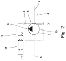
- FIG. 2 corresponds largely to the embodiment of FIG. 1 ,
- the rotor 3 of the piston pump 5 about the rotation axis 4, which is coaxial with the rotation axis 4 rotatably connected to the second drive shaft 7, during the Cam ring 2 of the piston pump 5 with the diametrically to the second output shaft 7 extending first output shaft 6 is rotatably connected.
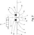
- the first piston pump 5 conveys from its pressure port 8 via a first hydraulic line 13 to the pressure port 14 of the second piston pump 5 '.
- the suction ports 10 and 15 of the first piston pump 5 'and the second piston pump are connected to each other via a second hydraulic line 16.
- a 2/2 solenoid valve 11 is arranged, which opens in its one position the valve passage and closes in the other position.
- the rotor 3 of the first piston pump 5 is rotatably connected coaxially to the rotation axis 4 with the first output shaft 6, while the rotor 17 of the second piston pump 5 'with the diametrically to the first output shaft 6 extending second output shaft 7 is rotatably connected.
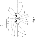
- FIG. 4 corresponds largely to the embodiment of FIG. 3 ,
- the first cam ring 12 of the first piston pump 5 and the second cam ring 12 'of the second piston pump 5' are rotatably driven about the rotation axis 4 coaxial with the rotation axis 4 with the first output shaft 6 and the second drive shaft 7 are rotatably connected ,
- FIG. 5 is driven by the driven gear 1, a first cam ring 12 of a first piston pump 5, a second cam ring 12 'of a second piston pump 5' and a differential carrier 18 of a between the two piston pumps 5 and 5 'arranged differential compensation 19 rotatably driven about the rotation axis 4.
- a to the axis of rotation 4 coaxial with a first Achswellenrad 23 connected first output shaft 20 of the differential compensation 19 is rotatably connected to the first output shaft 6.
- a to the axis of rotation 4 coaxial with a second axle 24 connected second output shaft 21 of the differential compensation 19 is rotatably connected to the second output shaft 7.
Landscapes
- Engineering & Computer Science (AREA)
- Mechanical Engineering (AREA)
- General Engineering & Computer Science (AREA)
- Chemical & Material Sciences (AREA)
- Combustion & Propulsion (AREA)
- Transportation (AREA)
- Physics & Mathematics (AREA)
- Fluid Mechanics (AREA)
- Retarders (AREA)
Abstract
Description
- Die Erfindung bezieht sich auf eine Ausgleichsgetriebeeinheit für zweiachsgetriebene Kraftfahrzeuge, mit einer ersten Abtriebswelle zur Drehmomentübertragung auf eine erste Fahrzeugachse und mit einer zweiten Abtriebswelle zur Drehmomentübertragung auf eine zweite Fahrzeugachse, mit einem zwischen die beiden Abtriebswellen eingeschalteten Ausgleichsgetriebe.
- Bei einer Ausgleichsgetriebeeinheit mit einem Kegelraddifferential ist es bekannt, wobei eine Sperrung des Kegelraddifferentials mit Hilfe einer Hydraulikpumpe erfolgt. Dies ist aufgrund der Vielzahl der Bauteile aufwendig und teuer und benötigt einen großen Bauraum.
- Aufgabe der Erfindung ist es eine Ausgleichsgetriebeeinheit der eingangs genannten Art zu schaffen, die bei reduzierter Anzahl an Bauteilen einen geringeren Bauraum benötigt.
- Diese Aufgabe wird erfindungsgemäß dadurch gelöst, dass das Ausgleichsgetriebe eine abhängig von einer Drehzahldifferenz zwischen den beiden Abtriebswellen eine antreibbare Hydraulikpumpe ist, die Hydrauliköl mit einem Volumenstrom entsprechend der Drehzahldifferenz fördert und mit einem hydraulischen Steuerkreis mit einer Hydraulikleitung, die eine Verbindung des Druckanschlusses der Hydraulikpumpe mit dem Sauganschluss der Hydraulikpumpe herstellt.
- Der Volumenstrom wird dabei von der Steuereinheit so gesteuert, dass sich die Drehzahlen der Antriebswellen aneinander oder an eine Vorgabedrehzahldifferenz angleichen.
- Die Hydraulikpumpe ist vorzugsweise eine Kolbenpumpe, durch die höhere Drücke und damit höhere Kräfte erzeugt werden können.
- In der Hydraulikleitung kann eine Ventileinheit angeordnet sein, durch die der Volumenstrom des die Hydraulikleitung durchströmenden Hydrauliköls entsprechend der Drehzahldifferenz regelbar ist.
- Dabei ist die Ventileinheit zur schnellen und präzisen Regelung vorzugsweise eine von einer Steuereinheit ansteuerbare Magnetventileinheit.
- In einer vorteilhaften Ausbildung kann die Hydraulikpumpe einen um eine Drehachse drehbaren Rotor und einen um die Drehachse drehbaren Steuerkurvenring aufweisen, wobei der Rotor mit der zur Drehachse koaxialen ersten Fahrzeugachse fest verbunden ist und wobei der Steuerkurvenring mit der zur Drehachse koaxialen zweiten Fahrzeugachse fest verbunden und von einem Abtriebsrad des motorischen Antriebs drehbar antreibbar ist.
- In Umkehrung der Zuordnung der Fahrzeugachsen kann auch die Hydraulikpumpe einen um eine Drehachse drehbaren Rotor und einen um eine um die Drehachse drehbaren Steuerkurvenring aufweisen, wobei der Rotor mit der zur Drehachse koaxialen zweiten Fahrzeugachse fest verbunden ist und wobei der Steuerkurvenring mit der zur Drehachse koaxialen ersten Fahrzeugachse fest verbunden und von einem Abtriebsrad des motorischen Antriebs drehbar antreibbar ist.
- Eine weiter vorteilhafte Ausbildung besteht darin, dass eine erste Hydraulikpumpe einen um eine Drehachse drehbaren ersten Rotor und einen um die Drehachse drehbaren ersten Steuerkurvenring aufweist und eine zweite Hydraulikpumpe einen um die Drehachse drehbaren zweiten Rotor und einen um die Drehachse drehbaren zweiten Steuerkurvenring aufweist, wobei der erste Steuerkurvenring und der zweite Steuerkurvenring gemeinsam von einem Abtriebsrad des motorischen Antriebs drehbar antreibbar sind, wobei die Druckanschlüsse der ersten Hydraulikpumpe und der zweiten Hydraulikpumpe über eine erste Hydraulikleitung miteinander verbunden sind, in der eine von einer Steuereinheit ansteuerbare erste Ventileinheit angeordnet ist, die den Volumenstrom in der ersten Hydraulikleitung steuert und wobei die Sauganschlüsse der ersten Hydraulikpumpe und der zweiten Hydraulikpumpe über eine zweite Hydraulikleitung miteinander verbunden sind.
- In Umkehrung der Zuordnung der Fahrzeugachsen kann auch eine erste Hydraulikpumpe einen um eine Drehachse drehbaren ersten Rotor und einen um die Drehachse drehbaren ersten Steuerkurvenring aufweist und eine zweite Hydraulikpumpe einen um die Drehachse drehbaren zweiten Rotor und einen um die Drehachse drehbaren zweiten Steuerkurvenring aufweist, wobei der erste Rotor und der zweite Rotor gemeinsam von einem Abtriebsrad des motorischen Antriebs drehbar antreibbar sind, wobei die Druckanschlüsse der ersten Hydraulikpumpe und der zweiten Hydraulikpumpe über eine erste Hydraulikleitung miteinander verbunden sind, in der eine von einer Steuereinheit ansteuerbare erste Ventileinheit angeordnet ist, die den Volumenstrom in der ersten Hydraulikleitung steuert und wobei die Sauganschlüsse der ersten Hydraulikpumpe und der zweiten Hydraulikpumpe über eine zweite Hydraulikleitung miteinander verbunden sind.
- Dabei ist die erste Ventileinheit vorzugsweise ein 2/2 Magnetproportionalventil.
- Noch eine weiter vorteilhafte Ausbildung besteht darin, dass eine erste Hydraulikpumpe einen um eine Drehachse drehbaren ersten Rotor und einen um die Drehachse drehbaren ersten Steuerkurvenring aufweist und eine zweite Hydraulikpumpe einen um die Drehachse drehbaren zweiten Rotor und einen um die Drehachse drehbaren zweiten Steuerkurvenring aufweist, wobei ein Differentialkorb eines Ausgleichsdifferentials sowie der erste Steuerkurvenring und der zweite Steuerkurvenring gemeinsam von einem Abtriebsrad des motorischen Antriebs drehbar antreibbar sind, wobei von einem ersten Achswellenrad des Ausgleichsdifferentials die erste Fahrzeugachse und von einem zweiten Achswellenrad des Ausgleichsdifferentials die zweite Fahrzeugachse drehbar antreibbar sind, und wobei die Druckanschlüsse der ersten Hydraulikpumpe und der zweiten Hydraulikpumpe über eine erste Hydraulikleitung miteinander verbunden sind, in der eine von einer Steuereinheit ansteuerbare zweite Ventileinheit angeordnet ist, die den Volumenstrom in der ersten Hydraulikleitung steuert und wobei die Sauganschlüsse der ersten Hydraulikpumpe und der zweiten Hydraulikpumpe über eine zweite Hydraulikleitung miteinander verbunden sind, in der die von der Steuereinheit ansteuerbare Magnetventileinheit angeordnet ist, die den Volumenstrom in der zweiten Hydraulikleitung steuert.
- Dabei ist vorzugsweise die zweite Ventileinheit ein 2/4 Magnetproportionalventil.
- Ausführungsbeispiele der Erfindung sind in der Zeichnung dargestellt und werden im Folgenden näher beschrieben. Es zeigen
- Figur 1
- eine Prinzipdarstellung eines ersten Ausführungsbeispiels einer Ausgleichsgetriebeeinheit
- Figur 2
- eine Prinzipdarstellung eines zweiten Ausführungsbeispiels einer Ausgleichsgetriebeeinheit
- Figur 3
- eine Prinzipdarstellung eines dritten Ausführungsbeispiels einer Ausgleichsgetriebeeinheit
- Figur 4
- eine Prinzipdarstellung eines vierten Ausführungsbeispiels einer Ausgleichsgetriebeeinheit
- Figur 5
- eine Prinzipdarstellung eines fünften Ausführungsbeispiels einer Ausgleichsgetriebeeinheit.
- Die in den Figuren dargestellten Ausgleichsgetriebeeinheiten eines Kraftfahrzeugs weisen ein Abtriebsrad 1 auf, das von einem nicht dargestellten motorischen Antrieb des Kraftfahrzeugs drehbar antreibbar sind.
- Von dem Abtriebsrad 1 wird ein Steuerkurvenring 2 oder ein Rotor 3 einer Kolbenpumpe 5 um eine Drehachse 4 drehbar angetrieben.
- Koaxial zur Drehachse 4 weist der Rotor 3 oder der Steuerkurvenring 2 sich zueinander diametral erstreckend eine erste Abtriebswelle 6 zur Antriebsübertragung auf eine nicht dargestellte erste Fahrzeugachse und eine zweite Abtriebswelle 7 zur Antriebsübertragung auf eine nicht dargestellte zweite Fahrzeugachse auf.
- Der Volumenstrom der Kolbenpumpe 5 ist durch ein Mehrwege-Magnetventil abhängig von einer Drehzahldifferenz zwischen den Drehzahlen der beiden Abtriebswellen 6 und 7 steuerbar.
- Diese Drehzahldifferenz kann sich unmittelbar auf die Drehzahlen der beiden Abtriebswellen 6 und 7 beziehen, wenn die beiden Fahrzeugachsen mit denselben Drehzahlen angetrieben werden.
- Sind die Drehzahlen der beiden Fahrzeugachsen unterschiedlich, so bezieht sich die Drehzahldifferenz auf die Abweichung von einer Vorgabedrehzahldifferenz der Drehzahlen.
- Das Mehrwege-Magnetventil und damit der Volumenstrom wird von einer nicht dargestellten Regeleinheit so geregelt, dass sich die Drehzahlen aneinander oder an die Vorgabedrehzahldifferenz angleichen.
- Bei dem Ausführungsbeispiel der
Figur 1 wird von dem Abtriebsrad 1 der Steuerkurvenring 2 der Kolbenpumpe 5 um die Drehachse 4 drehbar angetrieben. Dabei fördert die Kolbenpumpe 5 von ihrem Druckanschluss 8 Hydrauliköl über eine Hydraulikleitung 9 zu ihrem Sauganschluss 10. In der Hydraulikleitung 9 ist ein 2/2 Magnetwegeventil 11 angeordnet, das in seiner einen Stellposition den Ventildurchgang öffnet und in der anderen Stellposition schließt. - Der Rotor 3 der Kolbenpumpe 5 ist koaxial zur Drehachse 4 mit der ersten Antriebswelle 6 drehfest verbunden, während der Steuerkurvenring 2 der Kolbenpumpe 5 mit der sich diametral zur ersten Abtriebswelle 6 erstreckenden zweiten Abtriebswelle 7 drehfest verbunden ist.
- Das Ausführungsbeispiel der
Figur 2 entspricht weitgehend dem Ausführungsbeispiel derFigur 1 . Im Unterschied zuFigur 1 wird von dem Abtriebsrad 1 der Rotor 3 der Kolbenpumpe 5 um die Drehachse 4 drehbar angetrieben, der koaxial zur Drehachse 4 mit der zweiten Antriebswelle 7 drehfest verbunden ist, während der Steuerkurvenring 2 der Kolbenpumpe 5 mit der sich diametral zur zweiten Abtriebswelle 7 erstreckenden ersten Abtriebswelle 6 drehfest verbunden ist. - Bei dem Ausführungbeispiel der
Figur 3 wird von dem Abtriebsrad 1 sowohl ein erster Steuerkurvenring 12 einer ersten Kolbenpumpe 5 als auch ein zweiter Steuerkurvenring 12' einer zweiten Kolbenpumpe 5' um die Drehachse 4 drehbar angetrieben. Dabei fördert die erste Kolbenpumpe 5 von ihrem Druckanschluss 8 über eine erste Hydraulikleitung 13 zu dem Druckanschluss 14 der zweiten Kolbenpumpe 5'. Die Sauganschlüsse 10 und 15 der ersten Kolbenpumpe 5' und der zweiten Kolbenpumpe sind über eine zweite Hydraulikleitung 16 miteinander verbunden. - In der ersten Hydraulikleitung 13 ist ein 2/2 Magnetwegeventil 11 angeordnet, das in seiner einen Stellposition den Ventildurchgang öffnet und in der anderen Stellposition schließt.
- Der Rotor 3 der ersten Kolbenpumpe 5 ist koaxial zur Drehachse 4 mit der ersten Abtriebswelle 6 drehfest verbunden, während der Rotor 17 der zweiten Kolbenpumpe 5' mit der sich diametral zur ersten Abtriebswelle 6 erstreckenden zweiten Abtriebswelle 7 drehfest verbunden ist.
- Das Ausführungsbeispiel der
Figur 4 entspricht weitgehend dem Ausführungsbeispiel derFigur 3 . Im Unterschied zuFigur 3 werden von dem Abtriebsrad 1 der erste Steuerkurvenring 12 der ersten Kolbenpumpe 5 und der zweite Steuerkurvenring 12' der zweiten Kolbenpumpe 5' um die Drehachse 4 drehbar angetrieben, die koaxial zur Drehachse 4 mit der ersten Abtriebswelle 6 bzw. der zweiten Antriebswelle 7 drehfest verbunden sind. - Bei dem Ausführungsbeispiel der
Figur 5 wird von dem Abtriebsrad 1 ein erster Steuerkurvenring 12 einer ersten Kolbenpumpe 5, ein zweiter Steuerkurvenring 12' einer zweiten Kolbenpumpe 5' sowie ein Differentialkorb 18 eines zwischen den beiden Kolbenpumpen 5 und 5' angeordneten Ausgleichsdifferentials 19 um die Drehachse 4 drehbar angetrieben. - Eine zur Drechachse 4 koaxiale mit einem ersten Achswellenrad 23 verbundene erste Abtriebswelle 20 des Ausgleichsdifferentials 19 ist mit der ersten Abtriebswelle 6 drehfest verbunden.
- Eine zur Drechachse 4 koaxiale mit einem zweiten Achswellenrad 24 verbundene zweite Abtriebswelle 21 des Ausgleichsdifferentials 19 ist mit der zweiten Abtriebswelle 7 drehfest verbunden.
- Die Druckanschlüsse 8 und 14 der ersten Hydraulikpumpe 5 und der zweiten Hydraulikpumpe 5' sind über eine erste Hydraulikleitung 9 miteinander verbunden, in der ein 2/4 Magnetventil 22 angeordnet ist, das den Volumenstrom in der ersten Hydraulikleitung 9 steuert. Die Sauganschlüsse 10 und 15 der ersten Hydraulikpumpe 5 und der zweiten Hydraulikpumpe 5' sind über eine zweite Hydraulikleitung 16 miteinander verbunden, die ebenfalls über das 2/4 Magnetventil 22 führt, die die Volumenströme in der ersten Hydraulikleitung 9 und in der zweiten Hydraulikleitung 16 steuert.
-
- 1
- Abtriebsrad
- 2
- Steuerkurvenring
- 3
- Rotor
- 4
- Drehachse
- 5
- erste Kolbenpumpe
- 5'
- zweite Kolbenpumpe
- 6
- erste Abtriebswelle
- 7
- zweite Abtriebswelle
- 8
- Druckanschluss
- 9
- Hydraulikleitung
- 10
- Sauganschluss
- 11
- 2/2 Magnetproportionalventil
- 12
- erster Steuerkurvenring
- 12'
- zweiter Steuerkurvenring
- 13
- erste Hydraulikleitung
- 14
- Druckanschluss
- 15
- Sauganschluss erste Kolbenpumpe
- 16
- zweite Hydraulikleitung
- 17
- Rotor zweite Kolbenpumpe
- 18
- Differentialkorb
- 19
- Ausgleichsdifferential
- 20
- erste Abtriebswelle
- 21
- zweite Abtriebswelle
- 22
- 2/4 Magnetventil
- 23
- erstes Achswellenrad
- 24
- zweites Achswellenrad
Claims (11)
- Ausgleichsgetriebeeinheit für zweiachsgetriebene Kraftfahrzeuge, mit einer ersten Abtriebswelle (6) zur Drehmomentübertragung auf eine erste Fahrzeugachse und mit einer zweiten Antriebswelle (7) zur Drehmomentübertragung auf eine zweite Fahrzeugachse, mit einem zwischen die beiden Abtriebswellen (6, 7) eingeschalteten Ausgleichsgetriebe, dadurch gekennzeichnet, dass das Ausgleichsgetriebe eine abhängig von einer Drehzahldifferenz zwischen den beiden Abtriebswellen (6, 7) antreibbare Hydraulikpumpe ist, die Hydrauliköl mit einem Volumenstrom entsprechend der Drehzahldifferenz fördert und mit einem hydraulischen Steuerkreis mit einer Hydraulikleitung (9, 13, 16), die eine Verbindung des Druckanschlusses (8, 14) der Hydraulikpumpe mit dem Sauganschluss (10, 15) der Hydraulikpumpe herstellt.
- Ausgleichsgetriebeeinheit nach Anspruch 1, dadurch gekennzeichnet, dass die Hydraulikpumpe eine Kolbenpumpe (5, 5') ist.
- Ausgleichsgetriebeeinheit nach Anspruch 1, dadurch gekennzeichnet, dass in der Hydraulikleitung (9, 13, 16) eine Ventileinheit angeordnet ist, durch die der Volumenstrom des die Hydraulikleitung (9, 13, 16) durchströmenden Hydrauliköls entsprechend der Drehzahldifferenz regelbar ist.
- Ausgleichsgetriebeeinheit nach Anspruch 3, dadurch gekennzeichnet, dass die Ventileinheit eine von einer Regeleinheit ansteuerbare Magnetventileinheit ist.
- Ausgleichsgetriebeeinheit nach einem der vorhergehenden Ansprüche, dadurch gekennzeichnet, dass die Hydraulikpumpe einen um eine Drehachse (4) drehbaren Rotor (3) und einen um die Drehachse (4) drehbaren Steuerkurvenring (2) aufweist, wobei der Rotor (3) mit der zur Drehachse (4) koaxialen ersten Fahrzeugachse fest verbunden ist und wobei der Steuerkurvenring (2) mit der zur Drehachse (4) koaxialen zweiten Fahrzeugachse fest verbunden und von einem Abtriebsrad (1) des motorischen Antriebs drehbar antreibbar ist.
- Ausgleichsgetriebeeinheit nach einem der Ansprüche 1 bis 4, dadurch gekennzeichnet, dass die Hydraulikpumpe einen um eine Drehachse (4) drehbaren Rotor (3) und einen um eine um die Drehachse (4) drehbaren Steuerkurvenring (2) aufweist, wobei der Rotor (3) mit der zur Drehachse (4) koaxialen zweiten Fahrzeugachse fest verbunden ist und wobei der Steuerkurvenring (2) mit der zur Drehachse (4) koaxialen ersten Fahrzeugachse fest verbunden und von einem Abtriebsrad (1) des motorischen Antriebs drehbar antreibbar ist.
- Ausgleichsgetriebeeinheit nach einem der Ansprüche 1 bis 4, dadurch gekennzeichnet, dass eine erste Hydraulikpumpe einen um eine Drehachse (4) drehbaren ersten Rotor (3) und einen um die Drehachse (4) drehbaren ersten Steuerkurvenring (12) aufweist und eine zweite Hydraulikpumpe einen um die Drehachse (4) drehbaren zweiten Rotor (17) und einen um die Drehachse (4) drehbaren zweiten Steuerkurvenring (12') aufweist, wobei der erste Steuerkurvenring (12) und der zweite Steuerkurvenring (12') gemeinsam von einem Abtriebsrad (1) des motorischen Antriebs drehbar antreibbar sind, wobei die Druckanschlüsse (8, 14) der ersten Hydraulikpumpe und der zweiten Hydraulikpumpe über eine erste Hydraulikleitung (13) miteinander verbunden sind, in der eine von einer Regeleinheit ansteuerbare erste Ventileinheit angeordnet ist, die den Volumenstrom in der ersten Hydraulikleitung (13) steuert und wobei die Sauganschlüsse (10, 15) der ersten Hydraulikpumpe und der zweiten Hydraulikpumpe über eine zweite Hydraulikleitung (16) miteinander verbunden sind.
- Ausgleichsgetriebeeinheit nach einem der Ansprüche 1 bis 4, dadurch gekennzeichnet, dass eine erste Hydraulikpumpe einen um eine Drehachse (4) drehbaren ersten Rotor (3) und einen um die Drehachse (4) drehbaren ersten Steuerkurvenring (12) aufweist und eine zweite Hydraulikpumpe einen um die Drehachse (4) drehbaren zweiten Rotor (17) und einen um die Drehachse (4) drehbaren zweiten Steuerkurvenring (12') aufweist, wobei der erste Rotor (3) und der zweite Rotor (17) gemeinsam von einem Abtriebsrad (1) des motorischen Antriebs drehbar antreibbar sind, wobei die Druckanschlüsse (8, 14) der ersten Hydraulikpumpe und der zweiten Hydraulikpumpe über eine erste Hydraulikleitung (9) miteinander verbunden sind, in der eine von einer Regeleinheit ansteuerbare erste Ventileinheit angeordnet ist, die den Volumenstrom in der ersten Hydraulikleitung steuert und wobei die Sauganschlüsse (10, 15) der ersten Hydraulikpumpe und der zweiten Hydraulikpumpe über eine zweite Hydraulikleitung (16) miteinander verbunden sind.
- Ausgleichsgetriebeeinheit nach einem der Ansprüche 7 und 8, dadurch gekennzeichnet, dass die erste Ventileinheit ein 2/2 Magnetproportionalventil (11) ist.
- Ausgleichsgetriebeeinheit nach einem der Ansprüche 1 bis 4, dadurch gekennzeichnet, dass eine erste Hydraulikpumpe einen um eine Drehachse (4) drehbaren ersten Rotor (3) und einen um die Drehachse (4) drehbaren ersten Steuerkurvenring (12) aufweist und eine zweite Hydraulikpumpe einen um die Drehachse (4) drehbaren zweiten Rotor (17) und einen um die Drehachse (4) drehbaren zweiten Steuerkurvenring (12') aufweist, wobei ein Differentialkorb (18) eines Ausgleichsdifferentials (19) sowie der erste Steuerkurvenring (12) und der zweite Steuerkurvenring (12') gemeinsam von einem Abtriebsrad (1) des motorischen Antriebs drehbar antreibbar sind, wobei von einem ersten Achswellenrad (23) des Ausgleichsdifferentials (19) die erste Fahrzeugachse und von einem zweiten Achswellenrad (24) des Ausgleichsdifferentials (19) die zweite Fahrzeugachse drehbar antreibbar sind, und wobei die Druckanschlüsse (8, 14) der ersten Hydraulikpumpe und der zweiten Hydraulikpumpe über eine erste Hydraulikleitung (13) miteinander verbunden sind, in der eine von einer Steuereinheit ansteuerbare zweite Ventileinheit angeordnet ist, die den Volumenstrom in der ersten Hydraulikleitung (13) steuert und wobei die Sauganschlüsse (10, 15) der ersten Hydraulikpumpe und der zweiten Hydraulikpumpe über eine zweite Hydraulikleitung (16) miteinander verbunden sind, in der die von der Steuereinheit ansteuerbare Magnetventileinheit angeordnet ist, die den Volumenstrom in der zweiten Hydraulikleitung (16) steuert.
- Ausgleichsgetriebeeinheit nach Anspruch 10, dadurch gekennzeichnet, dass die zweite Ventileinheit ein 2/4 Magnetventil (22) ist.
Applications Claiming Priority (2)
| Application Number | Priority Date | Filing Date | Title |
|---|---|---|---|
| DE102017223138 | 2017-12-19 | ||
| DE102018202028.0A DE102018202028A1 (de) | 2017-12-19 | 2018-02-09 | Ausgleichsgetriebeeinheit |
Publications (2)
| Publication Number | Publication Date |
|---|---|
| EP3501871A1 true EP3501871A1 (de) | 2019-06-26 |
| EP3501871B1 EP3501871B1 (de) | 2021-09-01 |
Family
ID=64362361
Family Applications (1)
| Application Number | Title | Priority Date | Filing Date |
|---|---|---|---|
| EP18206885.8A Active EP3501871B1 (de) | 2017-12-19 | 2018-11-19 | Ausgleichsgetriebeeinheit |
Country Status (1)
| Country | Link |
|---|---|
| EP (1) | EP3501871B1 (de) |
Citations (5)
| Publication number | Priority date | Publication date | Assignee | Title |
|---|---|---|---|---|
| US2583307A (en) * | 1950-06-17 | 1952-01-22 | Albert P Schneider | Hydraulic control system |
| EP0267419A2 (de) * | 1986-11-08 | 1988-05-18 | Robert Bosch Gmbh | Differentialsperre für Ausgleichsgetriebe |
| DE4330581A1 (de) * | 1992-09-09 | 1994-03-10 | Colombo Sige Brevetti | Differentialsperrsystem für eine Lenkantriebsachse |
| WO2005012768A1 (de) * | 2003-07-24 | 2005-02-10 | Gkn Driveline International Gmbh | Differentialgetriebe mit veränderlicher drehmomentverteilung zwischen den abtriebswellen |
| DE102006018661A1 (de) * | 2006-04-21 | 2007-10-25 | Audi Ag | Differenzialgetriebe für ein Kraftfahrzeug |
-
2018
- 2018-11-19 EP EP18206885.8A patent/EP3501871B1/de active Active
Patent Citations (5)
| Publication number | Priority date | Publication date | Assignee | Title |
|---|---|---|---|---|
| US2583307A (en) * | 1950-06-17 | 1952-01-22 | Albert P Schneider | Hydraulic control system |
| EP0267419A2 (de) * | 1986-11-08 | 1988-05-18 | Robert Bosch Gmbh | Differentialsperre für Ausgleichsgetriebe |
| DE4330581A1 (de) * | 1992-09-09 | 1994-03-10 | Colombo Sige Brevetti | Differentialsperrsystem für eine Lenkantriebsachse |
| WO2005012768A1 (de) * | 2003-07-24 | 2005-02-10 | Gkn Driveline International Gmbh | Differentialgetriebe mit veränderlicher drehmomentverteilung zwischen den abtriebswellen |
| DE102006018661A1 (de) * | 2006-04-21 | 2007-10-25 | Audi Ag | Differenzialgetriebe für ein Kraftfahrzeug |
Also Published As
| Publication number | Publication date |
|---|---|
| EP3501871B1 (de) | 2021-09-01 |
Similar Documents
| Publication | Publication Date | Title |
|---|---|---|
| EP3954926B1 (de) | Verfahren zur realisierung einer in der leistung limitierbaren drehmomente- und drehzahlschnittstelle für hydrostatische fahrantriebe | |
| DE3440219A1 (de) | Hydrostatische maschine | |
| DE102009011247A1 (de) | Hydrostatischer Antrieb | |
| DE3214688A1 (de) | Fluegelradpumpe | |
| EP2670639A1 (de) | Doppel-innenzahnradpumpe | |
| WO2019185263A1 (de) | Nebenabtriebsanordnung | |
| DE2701302C2 (de) | Automotive Steuerung für einen hydrostatischen Fahrantrieb | |
| WO2024052400A1 (de) | Pumpensystem für einen elektrischen achsantrieb | |
| WO2008148512A1 (de) | Drehmomentübertragungseinrichtung | |
| DE102014222322B3 (de) | Flügelzellenpumpe mit verbessertem Startverhalten | |
| WO2017045799A1 (de) | Verdrängerpumpe, verfahren zum betreiben einer verdrängerpumpe, lenksystem und getriebe | |
| DE10228800A1 (de) | Differenzialvorrichtung | |
| DE102018202028A1 (de) | Ausgleichsgetriebeeinheit | |
| EP3501871B1 (de) | Ausgleichsgetriebeeinheit | |
| DE3607709A1 (de) | Hydrostatische lenkanlage, insbesondere fuer kraftfahrzeuge | |
| DE19939474C2 (de) | Hydrostatischer Fahrantrieb mit Antischlupfregelung | |
| AT390305B (de) | Hydraulische steuereinheit | |
| EP3245425B1 (de) | Hydraulischer drehmomentwandler | |
| DE933973C (de) | Hydraulische Steuerung fuer die Kupplung in der Kraftuebertragung eines Kraftfahrzeuges | |
| DE2163456A1 (de) | Elektro-hydraulischer Schrittmotor | |
| DE3413683C2 (de) | ||
| DE102017209481A1 (de) | Fluidtechnische Ventileinrichtung sowie Verfahren zum Betreiben einer fluidtechnischen Ventileinrichtung | |
| DE102015107519A1 (de) | Verdrängerpumpe, Verfahren zum Betreiben einer Verdrängerpumpe, Lenksystem und Getriebe | |
| DE102015005343A1 (de) | Pumpenanordnung für ein Kraftfahrzeug | |
| DE920042C (de) | Hydraulisches Wendegetriebe mit einer bevorzugten Abtriebsdrehrichtung |
Legal Events
| Date | Code | Title | Description |
|---|---|---|---|
| PUAI | Public reference made under article 153(3) epc to a published international application that has entered the european phase |
Free format text: ORIGINAL CODE: 0009012 |
|
| STAA | Information on the status of an ep patent application or granted ep patent |
Free format text: STATUS: THE APPLICATION HAS BEEN PUBLISHED |
|
| AK | Designated contracting states |
Kind code of ref document: A1 Designated state(s): AL AT BE BG CH CY CZ DE DK EE ES FI FR GB GR HR HU IE IS IT LI LT LU LV MC MK MT NL NO PL PT RO RS SE SI SK SM TR |
|
| AX | Request for extension of the european patent |
Extension state: BA ME |
|
| STAA | Information on the status of an ep patent application or granted ep patent |
Free format text: STATUS: REQUEST FOR EXAMINATION WAS MADE |
|
| 17P | Request for examination filed |
Effective date: 20191212 |
|
| STAA | Information on the status of an ep patent application or granted ep patent |
Free format text: STATUS: EXAMINATION IS IN PROGRESS |
|
| 17Q | First examination report despatched |
Effective date: 20200508 |
|
| REG | Reference to a national code |
Ref country code: DE Ref legal event code: R079 Ref document number: 502018006811 Country of ref document: DE Free format text: PREVIOUS MAIN CLASS: B60K0017160000 Ipc: B60K0023040000 |
|
| RIC1 | Information provided on ipc code assigned before grant |
Ipc: B60K 17/16 20060101ALI20210305BHEP Ipc: F16H 48/27 20120101ALI20210305BHEP Ipc: B60K 23/04 20060101AFI20210305BHEP |
|
| GRAP | Despatch of communication of intention to grant a patent |
Free format text: ORIGINAL CODE: EPIDOSNIGR1 |
|
| STAA | Information on the status of an ep patent application or granted ep patent |
Free format text: STATUS: GRANT OF PATENT IS INTENDED |
|
| INTG | Intention to grant announced |
Effective date: 20210420 |
|
| GRAS | Grant fee paid |
Free format text: ORIGINAL CODE: EPIDOSNIGR3 |
|
| GRAA | (expected) grant |
Free format text: ORIGINAL CODE: 0009210 |
|
| STAA | Information on the status of an ep patent application or granted ep patent |
Free format text: STATUS: THE PATENT HAS BEEN GRANTED |
|
| AK | Designated contracting states |
Kind code of ref document: B1 Designated state(s): AL AT BE BG CH CY CZ DE DK EE ES FI FR GB GR HR HU IE IS IT LI LT LU LV MC MK MT NL NO PL PT RO RS SE SI SK SM TR |
|
| REG | Reference to a national code |
Ref country code: GB Ref legal event code: FG4D Free format text: NOT ENGLISH |
|
| REG | Reference to a national code |
Ref country code: CH Ref legal event code: EP Ref country code: AT Ref legal event code: REF Ref document number: 1425874 Country of ref document: AT Kind code of ref document: T Effective date: 20210915 |
|
| REG | Reference to a national code |
Ref country code: DE Ref legal event code: R096 Ref document number: 502018006811 Country of ref document: DE |
|
| REG | Reference to a national code |
Ref country code: IE Ref legal event code: FG4D Free format text: LANGUAGE OF EP DOCUMENT: GERMAN |
|
| REG | Reference to a national code |
Ref country code: LT Ref legal event code: MG9D |
|
| REG | Reference to a national code |
Ref country code: NL Ref legal event code: MP Effective date: 20210901 |
|
| PG25 | Lapsed in a contracting state [announced via postgrant information from national office to epo] |
Ref country code: FI Free format text: LAPSE BECAUSE OF FAILURE TO SUBMIT A TRANSLATION OF THE DESCRIPTION OR TO PAY THE FEE WITHIN THE PRESCRIBED TIME-LIMIT Effective date: 20210901 Ref country code: ES Free format text: LAPSE BECAUSE OF FAILURE TO SUBMIT A TRANSLATION OF THE DESCRIPTION OR TO PAY THE FEE WITHIN THE PRESCRIBED TIME-LIMIT Effective date: 20210901 Ref country code: HR Free format text: LAPSE BECAUSE OF FAILURE TO SUBMIT A TRANSLATION OF THE DESCRIPTION OR TO PAY THE FEE WITHIN THE PRESCRIBED TIME-LIMIT Effective date: 20210901 Ref country code: SE Free format text: LAPSE BECAUSE OF FAILURE TO SUBMIT A TRANSLATION OF THE DESCRIPTION OR TO PAY THE FEE WITHIN THE PRESCRIBED TIME-LIMIT Effective date: 20210901 Ref country code: RS Free format text: LAPSE BECAUSE OF FAILURE TO SUBMIT A TRANSLATION OF THE DESCRIPTION OR TO PAY THE FEE WITHIN THE PRESCRIBED TIME-LIMIT Effective date: 20210901 Ref country code: NO Free format text: LAPSE BECAUSE OF FAILURE TO SUBMIT A TRANSLATION OF THE DESCRIPTION OR TO PAY THE FEE WITHIN THE PRESCRIBED TIME-LIMIT Effective date: 20211201 Ref country code: BG Free format text: LAPSE BECAUSE OF FAILURE TO SUBMIT A TRANSLATION OF THE DESCRIPTION OR TO PAY THE FEE WITHIN THE PRESCRIBED TIME-LIMIT Effective date: 20211201 Ref country code: LT Free format text: LAPSE BECAUSE OF FAILURE TO SUBMIT A TRANSLATION OF THE DESCRIPTION OR TO PAY THE FEE WITHIN THE PRESCRIBED TIME-LIMIT Effective date: 20210901 |
|
| PG25 | Lapsed in a contracting state [announced via postgrant information from national office to epo] |
Ref country code: PL Free format text: LAPSE BECAUSE OF FAILURE TO SUBMIT A TRANSLATION OF THE DESCRIPTION OR TO PAY THE FEE WITHIN THE PRESCRIBED TIME-LIMIT Effective date: 20210901 Ref country code: LV Free format text: LAPSE BECAUSE OF FAILURE TO SUBMIT A TRANSLATION OF THE DESCRIPTION OR TO PAY THE FEE WITHIN THE PRESCRIBED TIME-LIMIT Effective date: 20210901 Ref country code: GR Free format text: LAPSE BECAUSE OF FAILURE TO SUBMIT A TRANSLATION OF THE DESCRIPTION OR TO PAY THE FEE WITHIN THE PRESCRIBED TIME-LIMIT Effective date: 20211202 |
|
| PG25 | Lapsed in a contracting state [announced via postgrant information from national office to epo] |
Ref country code: IS Free format text: LAPSE BECAUSE OF FAILURE TO SUBMIT A TRANSLATION OF THE DESCRIPTION OR TO PAY THE FEE WITHIN THE PRESCRIBED TIME-LIMIT Effective date: 20220101 Ref country code: SM Free format text: LAPSE BECAUSE OF FAILURE TO SUBMIT A TRANSLATION OF THE DESCRIPTION OR TO PAY THE FEE WITHIN THE PRESCRIBED TIME-LIMIT Effective date: 20210901 Ref country code: SK Free format text: LAPSE BECAUSE OF FAILURE TO SUBMIT A TRANSLATION OF THE DESCRIPTION OR TO PAY THE FEE WITHIN THE PRESCRIBED TIME-LIMIT Effective date: 20210901 Ref country code: RO Free format text: LAPSE BECAUSE OF FAILURE TO SUBMIT A TRANSLATION OF THE DESCRIPTION OR TO PAY THE FEE WITHIN THE PRESCRIBED TIME-LIMIT Effective date: 20210901 Ref country code: PT Free format text: LAPSE BECAUSE OF FAILURE TO SUBMIT A TRANSLATION OF THE DESCRIPTION OR TO PAY THE FEE WITHIN THE PRESCRIBED TIME-LIMIT Effective date: 20220103 Ref country code: NL Free format text: LAPSE BECAUSE OF FAILURE TO SUBMIT A TRANSLATION OF THE DESCRIPTION OR TO PAY THE FEE WITHIN THE PRESCRIBED TIME-LIMIT Effective date: 20210901 Ref country code: EE Free format text: LAPSE BECAUSE OF FAILURE TO SUBMIT A TRANSLATION OF THE DESCRIPTION OR TO PAY THE FEE WITHIN THE PRESCRIBED TIME-LIMIT Effective date: 20210901 Ref country code: CZ Free format text: LAPSE BECAUSE OF FAILURE TO SUBMIT A TRANSLATION OF THE DESCRIPTION OR TO PAY THE FEE WITHIN THE PRESCRIBED TIME-LIMIT Effective date: 20210901 Ref country code: AL Free format text: LAPSE BECAUSE OF FAILURE TO SUBMIT A TRANSLATION OF THE DESCRIPTION OR TO PAY THE FEE WITHIN THE PRESCRIBED TIME-LIMIT Effective date: 20210901 |
|
| REG | Reference to a national code |
Ref country code: DE Ref legal event code: R097 Ref document number: 502018006811 Country of ref document: DE |
|
| PG25 | Lapsed in a contracting state [announced via postgrant information from national office to epo] |
Ref country code: MC Free format text: LAPSE BECAUSE OF FAILURE TO SUBMIT A TRANSLATION OF THE DESCRIPTION OR TO PAY THE FEE WITHIN THE PRESCRIBED TIME-LIMIT Effective date: 20210901 |
|
| REG | Reference to a national code |
Ref country code: CH Ref legal event code: PL |
|
| PLBE | No opposition filed within time limit |
Free format text: ORIGINAL CODE: 0009261 |
|
| STAA | Information on the status of an ep patent application or granted ep patent |
Free format text: STATUS: NO OPPOSITION FILED WITHIN TIME LIMIT |
|
| PG25 | Lapsed in a contracting state [announced via postgrant information from national office to epo] |
Ref country code: LU Free format text: LAPSE BECAUSE OF NON-PAYMENT OF DUE FEES Effective date: 20211119 Ref country code: IT Free format text: LAPSE BECAUSE OF FAILURE TO SUBMIT A TRANSLATION OF THE DESCRIPTION OR TO PAY THE FEE WITHIN THE PRESCRIBED TIME-LIMIT Effective date: 20210901 Ref country code: DK Free format text: LAPSE BECAUSE OF FAILURE TO SUBMIT A TRANSLATION OF THE DESCRIPTION OR TO PAY THE FEE WITHIN THE PRESCRIBED TIME-LIMIT Effective date: 20210901 Ref country code: BE Free format text: LAPSE BECAUSE OF NON-PAYMENT OF DUE FEES Effective date: 20211130 |
|
| REG | Reference to a national code |
Ref country code: BE Ref legal event code: MM Effective date: 20211130 |
|
| 26N | No opposition filed |
Effective date: 20220602 |
|
| PG25 | Lapsed in a contracting state [announced via postgrant information from national office to epo] |
Ref country code: SI Free format text: LAPSE BECAUSE OF FAILURE TO SUBMIT A TRANSLATION OF THE DESCRIPTION OR TO PAY THE FEE WITHIN THE PRESCRIBED TIME-LIMIT Effective date: 20210901 Ref country code: LI Free format text: LAPSE BECAUSE OF NON-PAYMENT OF DUE FEES Effective date: 20211130 Ref country code: CH Free format text: LAPSE BECAUSE OF NON-PAYMENT OF DUE FEES Effective date: 20211130 |
|
| PG25 | Lapsed in a contracting state [announced via postgrant information from national office to epo] |
Ref country code: IE Free format text: LAPSE BECAUSE OF NON-PAYMENT OF DUE FEES Effective date: 20211119 |
|
| PG25 | Lapsed in a contracting state [announced via postgrant information from national office to epo] |
Ref country code: FR Free format text: LAPSE BECAUSE OF NON-PAYMENT OF DUE FEES Effective date: 20211130 |
|
| PG25 | Lapsed in a contracting state [announced via postgrant information from national office to epo] |
Ref country code: CY Free format text: LAPSE BECAUSE OF FAILURE TO SUBMIT A TRANSLATION OF THE DESCRIPTION OR TO PAY THE FEE WITHIN THE PRESCRIBED TIME-LIMIT Effective date: 20210901 |
|
| P01 | Opt-out of the competence of the unified patent court (upc) registered |
Effective date: 20230528 |
|
| GBPC | Gb: european patent ceased through non-payment of renewal fee |
Effective date: 20221119 |
|
| PG25 | Lapsed in a contracting state [announced via postgrant information from national office to epo] |
Ref country code: HU Free format text: LAPSE BECAUSE OF FAILURE TO SUBMIT A TRANSLATION OF THE DESCRIPTION OR TO PAY THE FEE WITHIN THE PRESCRIBED TIME-LIMIT; INVALID AB INITIO Effective date: 20181119 |
|
| PG25 | Lapsed in a contracting state [announced via postgrant information from national office to epo] |
Ref country code: GB Free format text: LAPSE BECAUSE OF NON-PAYMENT OF DUE FEES Effective date: 20221119 |
|
| PG25 | Lapsed in a contracting state [announced via postgrant information from national office to epo] |
Ref country code: MK Free format text: LAPSE BECAUSE OF FAILURE TO SUBMIT A TRANSLATION OF THE DESCRIPTION OR TO PAY THE FEE WITHIN THE PRESCRIBED TIME-LIMIT Effective date: 20210901 |
|
| PG25 | Lapsed in a contracting state [announced via postgrant information from national office to epo] |
Ref country code: TR Free format text: LAPSE BECAUSE OF FAILURE TO SUBMIT A TRANSLATION OF THE DESCRIPTION OR TO PAY THE FEE WITHIN THE PRESCRIBED TIME-LIMIT Effective date: 20210901 |
|
| PG25 | Lapsed in a contracting state [announced via postgrant information from national office to epo] |
Ref country code: MT Free format text: LAPSE BECAUSE OF FAILURE TO SUBMIT A TRANSLATION OF THE DESCRIPTION OR TO PAY THE FEE WITHIN THE PRESCRIBED TIME-LIMIT Effective date: 20210901 |
|
| REG | Reference to a national code |
Ref country code: AT Ref legal event code: MM01 Ref document number: 1425874 Country of ref document: AT Kind code of ref document: T Effective date: 20231119 |
|
| PG25 | Lapsed in a contracting state [announced via postgrant information from national office to epo] |
Ref country code: AT Free format text: LAPSE BECAUSE OF NON-PAYMENT OF DUE FEES Effective date: 20231119 |
|
| PG25 | Lapsed in a contracting state [announced via postgrant information from national office to epo] |
Ref country code: AT Free format text: LAPSE BECAUSE OF NON-PAYMENT OF DUE FEES Effective date: 20231119 |
|
| PGFP | Annual fee paid to national office [announced via postgrant information from national office to epo] |
Ref country code: DE Payment date: 20250923 Year of fee payment: 8 |
|
| PGFP | Annual fee paid to national office [announced via postgrant information from national office to epo] |
Ref country code: AT Payment date: 20260410 Year of fee payment: 5 |