EP3501763B1 - Cutting device, in particular for cutting webs - Google Patents
Cutting device, in particular for cutting webs Download PDFInfo
- Publication number
- EP3501763B1 EP3501763B1 EP18210333.3A EP18210333A EP3501763B1 EP 3501763 B1 EP3501763 B1 EP 3501763B1 EP 18210333 A EP18210333 A EP 18210333A EP 3501763 B1 EP3501763 B1 EP 3501763B1
- Authority
- EP
- European Patent Office
- Prior art keywords
- carriage
- guide
- cutting device
- cutting
- sleeve
- Prior art date
- Legal status (The legal status is an assumption and is not a legal conclusion. Google has not performed a legal analysis and makes no representation as to the accuracy of the status listed.)
- Active
Links
Images

Classifications
-
- B—PERFORMING OPERATIONS; TRANSPORTING
- B26—HAND CUTTING TOOLS; CUTTING; SEVERING
- B26D—CUTTING; DETAILS COMMON TO MACHINES FOR PERFORATING, PUNCHING, CUTTING-OUT, STAMPING-OUT OR SEVERING
- B26D7/00—Details of apparatus for cutting, cutting-out, stamping-out, punching, perforating, or severing by means other than cutting
- B26D7/22—Safety devices specially adapted for cutting machines
-
- B—PERFORMING OPERATIONS; TRANSPORTING
- B26—HAND CUTTING TOOLS; CUTTING; SEVERING
- B26D—CUTTING; DETAILS COMMON TO MACHINES FOR PERFORATING, PUNCHING, CUTTING-OUT, STAMPING-OUT OR SEVERING
- B26D1/00—Cutting through work characterised by the nature or movement of the cutting member or particular materials not otherwise provided for; Apparatus or machines therefor; Cutting members therefor
- B26D1/01—Cutting through work characterised by the nature or movement of the cutting member or particular materials not otherwise provided for; Apparatus or machines therefor; Cutting members therefor involving a cutting member which does not travel with the work
- B26D1/04—Cutting through work characterised by the nature or movement of the cutting member or particular materials not otherwise provided for; Apparatus or machines therefor; Cutting members therefor involving a cutting member which does not travel with the work having a linearly-movable cutting member
- B26D1/06—Cutting through work characterised by the nature or movement of the cutting member or particular materials not otherwise provided for; Apparatus or machines therefor; Cutting members therefor involving a cutting member which does not travel with the work having a linearly-movable cutting member wherein the cutting member reciprocates
- B26D1/08—Cutting through work characterised by the nature or movement of the cutting member or particular materials not otherwise provided for; Apparatus or machines therefor; Cutting members therefor involving a cutting member which does not travel with the work having a linearly-movable cutting member wherein the cutting member reciprocates of the guillotine type
- B26D1/085—Cutting through work characterised by the nature or movement of the cutting member or particular materials not otherwise provided for; Apparatus or machines therefor; Cutting members therefor involving a cutting member which does not travel with the work having a linearly-movable cutting member wherein the cutting member reciprocates of the guillotine type for thin material, e.g. for sheets, strips or the like
-
- B—PERFORMING OPERATIONS; TRANSPORTING
- B26—HAND CUTTING TOOLS; CUTTING; SEVERING
- B26D—CUTTING; DETAILS COMMON TO MACHINES FOR PERFORATING, PUNCHING, CUTTING-OUT, STAMPING-OUT OR SEVERING
- B26D5/00—Arrangements for operating and controlling machines or devices for cutting, cutting-out, stamping-out, punching, perforating, or severing by means other than cutting
- B26D5/08—Means for actuating the cutting member to effect the cut
- B26D5/086—Electric, magnetic, piezoelectric, electro-magnetic means
-
- B—PERFORMING OPERATIONS; TRANSPORTING
- B26—HAND CUTTING TOOLS; CUTTING; SEVERING
- B26D—CUTTING; DETAILS COMMON TO MACHINES FOR PERFORATING, PUNCHING, CUTTING-OUT, STAMPING-OUT OR SEVERING
- B26D5/00—Arrangements for operating and controlling machines or devices for cutting, cutting-out, stamping-out, punching, perforating, or severing by means other than cutting
- B26D5/08—Means for actuating the cutting member to effect the cut
- B26D5/12—Fluid-pressure means
-
- B—PERFORMING OPERATIONS; TRANSPORTING
- B26—HAND CUTTING TOOLS; CUTTING; SEVERING
- B26D—CUTTING; DETAILS COMMON TO MACHINES FOR PERFORATING, PUNCHING, CUTTING-OUT, STAMPING-OUT OR SEVERING
- B26D5/00—Arrangements for operating and controlling machines or devices for cutting, cutting-out, stamping-out, punching, perforating, or severing by means other than cutting
- B26D5/08—Means for actuating the cutting member to effect the cut
- B26D5/16—Cam means
-
- B—PERFORMING OPERATIONS; TRANSPORTING
- B26—HAND CUTTING TOOLS; CUTTING; SEVERING
- B26D—CUTTING; DETAILS COMMON TO MACHINES FOR PERFORATING, PUNCHING, CUTTING-OUT, STAMPING-OUT OR SEVERING
- B26D7/00—Details of apparatus for cutting, cutting-out, stamping-out, punching, perforating, or severing by means other than cutting
- B26D7/0006—Means for guiding the cutter
-
- B—PERFORMING OPERATIONS; TRANSPORTING
- B26—HAND CUTTING TOOLS; CUTTING; SEVERING
- B26D—CUTTING; DETAILS COMMON TO MACHINES FOR PERFORATING, PUNCHING, CUTTING-OUT, STAMPING-OUT OR SEVERING
- B26D7/00—Details of apparatus for cutting, cutting-out, stamping-out, punching, perforating, or severing by means other than cutting
- B26D7/18—Means for removing cut-out material or waste
-
- B—PERFORMING OPERATIONS; TRANSPORTING
- B26—HAND CUTTING TOOLS; CUTTING; SEVERING
- B26D—CUTTING; DETAILS COMMON TO MACHINES FOR PERFORATING, PUNCHING, CUTTING-OUT, STAMPING-OUT OR SEVERING
- B26D7/00—Details of apparatus for cutting, cutting-out, stamping-out, punching, perforating, or severing by means other than cutting
- B26D7/18—Means for removing cut-out material or waste
- B26D7/1845—Means for removing cut-out material or waste by non mechanical means
- B26D7/1854—Means for removing cut-out material or waste by non mechanical means by air under pressure
-
- B—PERFORMING OPERATIONS; TRANSPORTING
- B26—HAND CUTTING TOOLS; CUTTING; SEVERING
- B26D—CUTTING; DETAILS COMMON TO MACHINES FOR PERFORATING, PUNCHING, CUTTING-OUT, STAMPING-OUT OR SEVERING
- B26D1/00—Cutting through work characterised by the nature or movement of the cutting member or particular materials not otherwise provided for; Apparatus or machines therefor; Cutting members therefor
- B26D1/0006—Cutting members therefor
- B26D2001/0066—Cutting members therefor having shearing means, e.g. shearing blades, abutting blades
-
- B—PERFORMING OPERATIONS; TRANSPORTING
- B26—HAND CUTTING TOOLS; CUTTING; SEVERING
- B26D—CUTTING; DETAILS COMMON TO MACHINES FOR PERFORATING, PUNCHING, CUTTING-OUT, STAMPING-OUT OR SEVERING
- B26D2210/00—Machines or methods used for cutting special materials
- B26D2210/11—Machines or methods used for cutting special materials for cutting web rolls
Definitions
- the present invention relates to a cutting device, in particular for the scissor-type cutting of webs.
- the strips obtained with the cutting device according to the present invention are used, for example, for creating abrasive discs for cutting tools.
- the webs of abrasive material are generally supplied in reels that are then unwound gradually for being fed to the cutting device, which then cuts the webs in a scissor-type way.
- the cutting of strips of abrasive material produces a substantial amount of dust and scraps which often obstruct the cutting device, which requires continuous maintenance and cleaning or even replacement.
- Known systems generally envisage a sliding guide system which cyclically moves a blade towards the respective fixed blade for performing the scissor-type cutting of the web in synchronised advancement with the longitudinal dimension of the strip to be obtained.
- the sliding system is made with a minimum section in order to have an exposed external surface area which is reduced to the bare minimum in order to minimise the amount of dust that can accumulate and penetrate inside.
- this implies a reduction in the structural rigidity of the cutting device which may be subject to breakages or misalignments that can interfere with the correct cutting of the web.
- the technical task underpinning the present invention is to provide a cutting device, in particular for the scissor-type cutting of webs, that obviates one or more drawbacks of the prior art as cited above.
- a further object of the present invention is to provide a cutting device, in particular for the scissor-type cutting of webs, which is structurally more rigid and reliable.
- the set technical task and specified aims are substantially attained by a cutting device, in particular for the scissor-type cutting of webs, comprising the technical characteristics set out in one or more of the appended claims.
- the cutting device according to the present invention is particularly indicated for cutting continuous webs into sections having a predetermined length. Substantially, the continuous web is gradually fed to the cutting device which then cuts it into sections of a predetermined length.
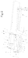
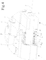
- the device 1 comprises a support structure 2, provided with a fixed blade 3.
- the support structure 2 may be connected to an overall support frame of the device 1, or to another structural part of the device 1.
- the device according to the present invention further comprises a carriage 4, movable with alternating motion along a movement direction X.
- the carriage 4 carries a mobile blade 5, configured and positioned to perform a scissor-type cut with the fixed blade 3.
- a motor means 6 is configured to move the carriage 4 according to an alternating movement along the movement direction X between a non-operating position, in which they are distanced from each other, and an operating position, in which the mobile blade 5 partially superposes the fixed blade 3 so as to carry out the cutting of a web.
- the blades 3,5 substantially open and close cyclically, at a predetermined working frequency.
- the web is fed to the blades 3,5 along a direction which is perpendicular to the movement direction X, in a continuous manner during the opening and closing cycle of the blades 3,5.
- the web is cut so as to separate a section, i.e. end portion of a predetermined length.
- the length of the sections can be adjusted by varying the supply speed of the web and/or the working frequency of the blades 3,5.
- a guide 7 is associated with the support structure 2.
- the guide 7 is in the form of a cylindrical stem.
- the carriage 4 is slidable on such guide 7 along the movement direction X.
- a sliding sleeve 11 is interposed between the carriage 4 and the guide 7.
- the sliding sleeve 11 is external and concentric to the guide 7.
- the sliding sleeve 11 is arranged in contact with both the carriage 4 and the guide 7, and has the function of reducing the friction between the carriage 4 and the guide 7.
- the sliding sleeve 11 comprises a rolling support member, e.g. a roller cage/ball cage, interposed between the guide 7 and the carriage 4 so as to define a sliding coupling.
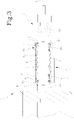
- the carriage 4 comprises a box body 12 fitted onto the guide 7.
- the guide 7 is inserted inside the sliding sleeve 11, which is closed into the box body 12.
- a support bushing 13 may be interposed, which substantially defines a sliding surface for the sleeve 11.
- the support bushing is kept in position by means of two blocking bushings 14, arranged at the ends of the support bushing 13.
- Seal means 8,10 are interposed between the guide 7 and the carriage 4, so as to define a chamber 9, concentric to the guide 7 and containing the sleeve 11.
- Such seal means 8,10 comprise for example a pair of seal rings, located on opposite sides of the sleeve 11 and concentric to the guide 7.
- the seal rings 8,10 can be housed in respective seats afforded in the carriage 4.
- a closed chamber is defined, inside which the sliding sleeve 11 is located.
- the chamber 9 has an annular conformation and closes the entire sliding coupling zone between the guide 7 and the sleeve 11.
- the blocking bushes 14 delimit, at least partially, a seat for the seal rings 8,10.
- the carriage 4 comprises two closing flanges 16, arranged in contact with the seal rings 8,10 and fixed to the box body 12 to retain the blocking bushings 14 and the seal rings 8, 10 themselves.
- the device according to the present invention comprises supply means 14a,15, provided for supplying air to the chamber 9 so as to maintain it at a greater pressure with respect to the surrounding environment.
- the pressurised air present inside the chamber 9 produces a flow that filters between the surface of the guide 7 and the surface of the seal rings 8,10 at the outlet from the chamber 9. Such flow prevents the scraps produced by cutting from slipping between the surface of the guide 7 and the seal rings 8,10, so that the scraps cannot contaminate the coupling zone between the sleeve 11 and the guide 7.
- the sleeve 11 especially if in the form of a ball cage, is notably less subject to wear with respect to what happens in devices currently available, as it works inside the chamber 9 which, thanks to the supply of air that maintains the pressure greater than ambient pressure, repels the dirt to the outside.
- the cleaning of the chamber 9, due to the pressure which is greater than ambient pressure, allows the section of the guide 7 to be increased, i.e. the diameter to be increased.
- the pressurised air present inside the chamber 9 produces a flow that filters between the surface of the guide 7 and the surface of the seal rings 8,10 at the outlet from the chamber 9.
- Such flow prevents the scraps produced by cutting from slipping between the surface of the guide 7 and the seal rings 8,10, so that also the seal rings 8,10, even if they are made with a larger diameter, are less subject to wear with respect to what happens in the currently available devices.
- the supply means for supplying air to the chamber 9 comprises a source of pressurised fluid, not shown, which is connected to the chamber 9 by means of a conduit 15 realised in the carriage 4, in particular realised in the box body 12.
- the conduit 15 may be defined by a hole.
- the conduit 15 may also be arranged in communication with one or more openings 14a afforded through the blocking bush 14, if this is provided. Such openings 14a, in turn, are in communication with the chamber 9.
- the pressurised fluid may come from a compressed air system, from a tank or from a compressor with which the cutting device according to the present invention may be provided.
- the cutting device according to the present invention comprises a pair of guides 7, in the form of parallel cylindrical stems.
- Each guide is fixed, at the ends thereof, to the support structure 2, e.g. through screws 2a.
- the carriage 4 comprises two box bodies 12, each of which is slidable on a respective guide 7 along the movement direction X.
- the two box bodies 12 are connected to each other rigidly by a support element 17 on which the mobile blade 5 is mounted.
- the structure of the carriage 4 described above is particularly rigid, and contributes to making the coupling between the fixed blade 3 and the mobile blade 5 particularly precise, so as to reduce the wear thereof and simultaneously the impacts and vibrations of the cutting device.
Landscapes
- Life Sciences & Earth Sciences (AREA)
- Forests & Forestry (AREA)
- Engineering & Computer Science (AREA)
- Mechanical Engineering (AREA)
- Treatment Of Fiber Materials (AREA)
Priority Applications (1)
| Application Number | Priority Date | Filing Date | Title |
|---|---|---|---|
| SI201830725T SI3501763T1 (sl) | 2017-12-20 | 2018-12-05 | Rezalna naprava, zlasti za rezanje trakov |
Applications Claiming Priority (1)
| Application Number | Priority Date | Filing Date | Title |
|---|---|---|---|
| IT201700147535 | 2017-12-20 |
Publications (2)
| Publication Number | Publication Date |
|---|---|
| EP3501763A1 EP3501763A1 (en) | 2019-06-26 |
| EP3501763B1 true EP3501763B1 (en) | 2022-06-29 |
Family
ID=61802270
Family Applications (1)
| Application Number | Title | Priority Date | Filing Date |
|---|---|---|---|
| EP18210333.3A Active EP3501763B1 (en) | 2017-12-20 | 2018-12-05 | Cutting device, in particular for cutting webs |
Country Status (4)
| Country | Link |
|---|---|
| US (1) | US10807267B2 (pl) |
| EP (1) | EP3501763B1 (pl) |
| PL (1) | PL3501763T3 (pl) |
| SI (1) | SI3501763T1 (pl) |
Citations (1)
| Publication number | Priority date | Publication date | Assignee | Title |
|---|---|---|---|---|
| US5131304A (en) * | 1988-03-14 | 1992-07-21 | Valmet Paper Machinery Inc. | Upper blade holder |
Family Cites Families (6)
| Publication number | Priority date | Publication date | Assignee | Title |
|---|---|---|---|---|
| SE317246B (pl) * | 1967-08-07 | 1969-11-10 | Tetra Pak Ab | |
| US3939743A (en) * | 1975-02-18 | 1976-02-24 | Sheldahl, Inc. | Punch for film products having improved slug removal facility |
| US4220063A (en) * | 1978-08-24 | 1980-09-02 | The Steelastic Company | Guillotine assembly |
| DE50307678D1 (de) * | 2002-03-15 | 2007-08-30 | Dienes Werke | Messerhalter mit spielfrei festzusetzender Messerhalterung |
| JP5237339B2 (ja) * | 2010-09-01 | 2013-07-17 | 平田機工株式会社 | 切断装置及び切断方法 |
| CN105364983B (zh) * | 2015-10-27 | 2017-10-03 | 苏州市东亿数控有限公司 | 一种pcb钻孔机自动排屑装置 |
-
2018
- 2018-12-05 SI SI201830725T patent/SI3501763T1/sl unknown
- 2018-12-05 EP EP18210333.3A patent/EP3501763B1/en active Active
- 2018-12-05 PL PL18210333.3T patent/PL3501763T3/pl unknown
- 2018-12-12 US US16/218,049 patent/US10807267B2/en active Active
Patent Citations (1)
| Publication number | Priority date | Publication date | Assignee | Title |
|---|---|---|---|---|
| US5131304A (en) * | 1988-03-14 | 1992-07-21 | Valmet Paper Machinery Inc. | Upper blade holder |
Also Published As
| Publication number | Publication date |
|---|---|
| EP3501763A1 (en) | 2019-06-26 |
| US10807267B2 (en) | 2020-10-20 |
| PL3501763T3 (pl) | 2022-10-03 |
| US20190184593A1 (en) | 2019-06-20 |
| SI3501763T1 (sl) | 2022-09-30 |
Similar Documents
| Publication | Publication Date | Title |
|---|---|---|
| JP6420603B2 (ja) | オーバートラベル圧力解放機構を備えた気体バネ | |
| US11866265B2 (en) | Transport system and transport method | |
| KR20130050847A (ko) | 절삭이 가능한 관로 청소 장치 | |
| CN104625923B (zh) | 金属砂光机 | |
| CN111566030B (zh) | 用于通过抽吸输送片材的辊式输送单元 | |
| US10807267B2 (en) | Cutting device, in particular for cutting webs | |
| US12036763B2 (en) | Pneumatic drive unit for a work tool of a relatively rigid material and corresponding machine for working a relatively rigid material | |
| US7603933B2 (en) | Strand oscillator assembly for choppers | |
| US20130000457A1 (en) | Rotary working apparatus | |
| US10022829B2 (en) | Apparatus and method for discharge and comminution of a chip | |
| US20110120283A1 (en) | Counter-Die Cylinder for a Machine for Stamping Sheet-Like Material and Method for Mounting/Removing a Cover | |
| EP2679876B1 (en) | Pig receiver assembly | |
| KR102186634B1 (ko) | 밴드 마감 장치 | |
| US10695998B2 (en) | Cutter for tire bead winder | |
| KR101663799B1 (ko) | 공기 배출 밸브를 갖는 전기 유압 액추에이터 | |
| US9777843B2 (en) | Steam valve and steam turbine | |
| AU2008207607B2 (en) | A guard | |
| CN1640634B (zh) | 带状材料切割装置及在带状材料中产生横向切口的方法 | |
| EP2341024A2 (de) | Rollenwickelvorrichtung und Verfahren zum Aufwickeln einer Materialbahn | |
| KR102326337B1 (ko) | 스티로폼 성형장치 | |
| WO2008093191A2 (en) | Smoothing machines | |
| KR100682093B1 (ko) | 긁힘 방지 기능을 갖는 압연소재 가이드 장치 | |
| EP1213064A2 (en) | Punching machine with vibration-damping device | |
| US20260042633A1 (en) | Interfolding machine and method for varying a length of sheet articles produced by the interfolding machine | |
| IT202300014964A1 (it) | Gruppo di finitura con copiatore ad assetto regolabile |
Legal Events
| Date | Code | Title | Description |
|---|---|---|---|
| PUAI | Public reference made under article 153(3) epc to a published international application that has entered the european phase |
Free format text: ORIGINAL CODE: 0009012 |
|
| STAA | Information on the status of an ep patent application or granted ep patent |
Free format text: STATUS: THE APPLICATION HAS BEEN PUBLISHED |
|
| AK | Designated contracting states |
Kind code of ref document: A1 Designated state(s): AL AT BE BG CH CY CZ DE DK EE ES FI FR GB GR HR HU IE IS IT LI LT LU LV MC MK MT NL NO PL PT RO RS SE SI SK SM TR |
|
| AX | Request for extension of the european patent |
Extension state: BA ME |
|
| STAA | Information on the status of an ep patent application or granted ep patent |
Free format text: STATUS: REQUEST FOR EXAMINATION WAS MADE |
|
| 17P | Request for examination filed |
Effective date: 20191016 |
|
| RBV | Designated contracting states (corrected) |
Designated state(s): AL AT BE BG CH CY CZ DE DK EE ES FI FR GB GR HR HU IE IS IT LI LT LU LV MC MK MT NL NO PL PT RO RS SE SI SK SM TR |
|
| STAA | Information on the status of an ep patent application or granted ep patent |
Free format text: STATUS: EXAMINATION IS IN PROGRESS |
|
| 17Q | First examination report despatched |
Effective date: 20201118 |
|
| GRAP | Despatch of communication of intention to grant a patent |
Free format text: ORIGINAL CODE: EPIDOSNIGR1 |
|
| STAA | Information on the status of an ep patent application or granted ep patent |
Free format text: STATUS: GRANT OF PATENT IS INTENDED |
|
| INTG | Intention to grant announced |
Effective date: 20220223 |
|
| GRAS | Grant fee paid |
Free format text: ORIGINAL CODE: EPIDOSNIGR3 |
|
| GRAA | (expected) grant |
Free format text: ORIGINAL CODE: 0009210 |
|
| STAA | Information on the status of an ep patent application or granted ep patent |
Free format text: STATUS: THE PATENT HAS BEEN GRANTED |
|
| AK | Designated contracting states |
Kind code of ref document: B1 Designated state(s): AL AT BE BG CH CY CZ DE DK EE ES FI FR GB GR HR HU IE IS IT LI LT LU LV MC MK MT NL NO PL PT RO RS SE SI SK SM TR |
|
| REG | Reference to a national code |
Ref country code: CH Ref legal event code: EP |
|
| REG | Reference to a national code |
Ref country code: DE Ref legal event code: R096 Ref document number: 602018037250 Country of ref document: DE |
|
| REG | Reference to a national code |
Ref country code: AT Ref legal event code: REF Ref document number: 1501016 Country of ref document: AT Kind code of ref document: T Effective date: 20220715 |
|
| REG | Reference to a national code |
Ref country code: IE Ref legal event code: FG4D |
|
| REG | Reference to a national code |
Ref country code: NL Ref legal event code: FP |
|
| REG | Reference to a national code |
Ref country code: LT Ref legal event code: MG9D |
|
| PG25 | Lapsed in a contracting state [announced via postgrant information from national office to epo] |
Ref country code: SE Free format text: LAPSE BECAUSE OF FAILURE TO SUBMIT A TRANSLATION OF THE DESCRIPTION OR TO PAY THE FEE WITHIN THE PRESCRIBED TIME-LIMIT Effective date: 20220629 Ref country code: NO Free format text: LAPSE BECAUSE OF FAILURE TO SUBMIT A TRANSLATION OF THE DESCRIPTION OR TO PAY THE FEE WITHIN THE PRESCRIBED TIME-LIMIT Effective date: 20220929 Ref country code: LT Free format text: LAPSE BECAUSE OF FAILURE TO SUBMIT A TRANSLATION OF THE DESCRIPTION OR TO PAY THE FEE WITHIN THE PRESCRIBED TIME-LIMIT Effective date: 20220629 Ref country code: HR Free format text: LAPSE BECAUSE OF FAILURE TO SUBMIT A TRANSLATION OF THE DESCRIPTION OR TO PAY THE FEE WITHIN THE PRESCRIBED TIME-LIMIT Effective date: 20220629 Ref country code: GR Free format text: LAPSE BECAUSE OF FAILURE TO SUBMIT A TRANSLATION OF THE DESCRIPTION OR TO PAY THE FEE WITHIN THE PRESCRIBED TIME-LIMIT Effective date: 20220930 Ref country code: FI Free format text: LAPSE BECAUSE OF FAILURE TO SUBMIT A TRANSLATION OF THE DESCRIPTION OR TO PAY THE FEE WITHIN THE PRESCRIBED TIME-LIMIT Effective date: 20220629 Ref country code: BG Free format text: LAPSE BECAUSE OF FAILURE TO SUBMIT A TRANSLATION OF THE DESCRIPTION OR TO PAY THE FEE WITHIN THE PRESCRIBED TIME-LIMIT Effective date: 20220929 |
|
| REG | Reference to a national code |
Ref country code: AT Ref legal event code: MK05 Ref document number: 1501016 Country of ref document: AT Kind code of ref document: T Effective date: 20220629 |
|
| PG25 | Lapsed in a contracting state [announced via postgrant information from national office to epo] |
Ref country code: RS Free format text: LAPSE BECAUSE OF FAILURE TO SUBMIT A TRANSLATION OF THE DESCRIPTION OR TO PAY THE FEE WITHIN THE PRESCRIBED TIME-LIMIT Effective date: 20220629 Ref country code: LV Free format text: LAPSE BECAUSE OF FAILURE TO SUBMIT A TRANSLATION OF THE DESCRIPTION OR TO PAY THE FEE WITHIN THE PRESCRIBED TIME-LIMIT Effective date: 20220629 |
|
| PG25 | Lapsed in a contracting state [announced via postgrant information from national office to epo] |
Ref country code: SM Free format text: LAPSE BECAUSE OF FAILURE TO SUBMIT A TRANSLATION OF THE DESCRIPTION OR TO PAY THE FEE WITHIN THE PRESCRIBED TIME-LIMIT Effective date: 20220629 Ref country code: SK Free format text: LAPSE BECAUSE OF FAILURE TO SUBMIT A TRANSLATION OF THE DESCRIPTION OR TO PAY THE FEE WITHIN THE PRESCRIBED TIME-LIMIT Effective date: 20220629 Ref country code: RO Free format text: LAPSE BECAUSE OF FAILURE TO SUBMIT A TRANSLATION OF THE DESCRIPTION OR TO PAY THE FEE WITHIN THE PRESCRIBED TIME-LIMIT Effective date: 20220629 Ref country code: PT Free format text: LAPSE BECAUSE OF FAILURE TO SUBMIT A TRANSLATION OF THE DESCRIPTION OR TO PAY THE FEE WITHIN THE PRESCRIBED TIME-LIMIT Effective date: 20221031 Ref country code: ES Free format text: LAPSE BECAUSE OF FAILURE TO SUBMIT A TRANSLATION OF THE DESCRIPTION OR TO PAY THE FEE WITHIN THE PRESCRIBED TIME-LIMIT Effective date: 20220629 Ref country code: EE Free format text: LAPSE BECAUSE OF FAILURE TO SUBMIT A TRANSLATION OF THE DESCRIPTION OR TO PAY THE FEE WITHIN THE PRESCRIBED TIME-LIMIT Effective date: 20220629 Ref country code: AT Free format text: LAPSE BECAUSE OF FAILURE TO SUBMIT A TRANSLATION OF THE DESCRIPTION OR TO PAY THE FEE WITHIN THE PRESCRIBED TIME-LIMIT Effective date: 20220629 |
|
| PG25 | Lapsed in a contracting state [announced via postgrant information from national office to epo] |
Ref country code: IS Free format text: LAPSE BECAUSE OF FAILURE TO SUBMIT A TRANSLATION OF THE DESCRIPTION OR TO PAY THE FEE WITHIN THE PRESCRIBED TIME-LIMIT Effective date: 20221029 |
|
| REG | Reference to a national code |
Ref country code: DE Ref legal event code: R097 Ref document number: 602018037250 Country of ref document: DE |
|
| PG25 | Lapsed in a contracting state [announced via postgrant information from national office to epo] |
Ref country code: AL Free format text: LAPSE BECAUSE OF FAILURE TO SUBMIT A TRANSLATION OF THE DESCRIPTION OR TO PAY THE FEE WITHIN THE PRESCRIBED TIME-LIMIT Effective date: 20220629 |
|
| PG25 | Lapsed in a contracting state [announced via postgrant information from national office to epo] |
Ref country code: DK Free format text: LAPSE BECAUSE OF FAILURE TO SUBMIT A TRANSLATION OF THE DESCRIPTION OR TO PAY THE FEE WITHIN THE PRESCRIBED TIME-LIMIT Effective date: 20220629 Ref country code: CZ Free format text: LAPSE BECAUSE OF FAILURE TO SUBMIT A TRANSLATION OF THE DESCRIPTION OR TO PAY THE FEE WITHIN THE PRESCRIBED TIME-LIMIT Effective date: 20220629 |
|
| PLBE | No opposition filed within time limit |
Free format text: ORIGINAL CODE: 0009261 |
|
| STAA | Information on the status of an ep patent application or granted ep patent |
Free format text: STATUS: NO OPPOSITION FILED WITHIN TIME LIMIT |
|
| 26N | No opposition filed |
Effective date: 20230330 |
|
| P01 | Opt-out of the competence of the unified patent court (upc) registered |
Effective date: 20230601 |
|
| REG | Reference to a national code |
Ref country code: CH Ref legal event code: PL |
|
| REG | Reference to a national code |
Ref country code: BE Ref legal event code: MM Effective date: 20221231 |
|
| PG25 | Lapsed in a contracting state [announced via postgrant information from national office to epo] |
Ref country code: LU Free format text: LAPSE BECAUSE OF NON-PAYMENT OF DUE FEES Effective date: 20221205 |
|
| PG25 | Lapsed in a contracting state [announced via postgrant information from national office to epo] |
Ref country code: LI Free format text: LAPSE BECAUSE OF NON-PAYMENT OF DUE FEES Effective date: 20221231 Ref country code: IE Free format text: LAPSE BECAUSE OF NON-PAYMENT OF DUE FEES Effective date: 20221205 Ref country code: CH Free format text: LAPSE BECAUSE OF NON-PAYMENT OF DUE FEES Effective date: 20221231 |
|
| PG25 | Lapsed in a contracting state [announced via postgrant information from national office to epo] |
Ref country code: BE Free format text: LAPSE BECAUSE OF NON-PAYMENT OF DUE FEES Effective date: 20221231 |
|
| PG25 | Lapsed in a contracting state [announced via postgrant information from national office to epo] |
Ref country code: HU Free format text: LAPSE BECAUSE OF FAILURE TO SUBMIT A TRANSLATION OF THE DESCRIPTION OR TO PAY THE FEE WITHIN THE PRESCRIBED TIME-LIMIT; INVALID AB INITIO Effective date: 20181205 |
|
| PG25 | Lapsed in a contracting state [announced via postgrant information from national office to epo] |
Ref country code: CY Free format text: LAPSE BECAUSE OF FAILURE TO SUBMIT A TRANSLATION OF THE DESCRIPTION OR TO PAY THE FEE WITHIN THE PRESCRIBED TIME-LIMIT Effective date: 20220629 |
|
| PG25 | Lapsed in a contracting state [announced via postgrant information from national office to epo] |
Ref country code: MK Free format text: LAPSE BECAUSE OF FAILURE TO SUBMIT A TRANSLATION OF THE DESCRIPTION OR TO PAY THE FEE WITHIN THE PRESCRIBED TIME-LIMIT Effective date: 20220629 |
|
| PG25 | Lapsed in a contracting state [announced via postgrant information from national office to epo] |
Ref country code: MC Free format text: LAPSE BECAUSE OF FAILURE TO SUBMIT A TRANSLATION OF THE DESCRIPTION OR TO PAY THE FEE WITHIN THE PRESCRIBED TIME-LIMIT Effective date: 20220629 |
|
| PG25 | Lapsed in a contracting state [announced via postgrant information from national office to epo] |
Ref country code: MC Free format text: LAPSE BECAUSE OF FAILURE TO SUBMIT A TRANSLATION OF THE DESCRIPTION OR TO PAY THE FEE WITHIN THE PRESCRIBED TIME-LIMIT Effective date: 20220629 |
|
| PG25 | Lapsed in a contracting state [announced via postgrant information from national office to epo] |
Ref country code: MT Free format text: LAPSE BECAUSE OF FAILURE TO SUBMIT A TRANSLATION OF THE DESCRIPTION OR TO PAY THE FEE WITHIN THE PRESCRIBED TIME-LIMIT Effective date: 20220629 |
|
| PG25 | Lapsed in a contracting state [announced via postgrant information from national office to epo] |
Ref country code: BG Free format text: LAPSE BECAUSE OF FAILURE TO SUBMIT A TRANSLATION OF THE DESCRIPTION OR TO PAY THE FEE WITHIN THE PRESCRIBED TIME-LIMIT Effective date: 20220629 |
|
| PG25 | Lapsed in a contracting state [announced via postgrant information from national office to epo] |
Ref country code: BG Free format text: LAPSE BECAUSE OF FAILURE TO SUBMIT A TRANSLATION OF THE DESCRIPTION OR TO PAY THE FEE WITHIN THE PRESCRIBED TIME-LIMIT Effective date: 20220629 |
|
| PGFP | Annual fee paid to national office [announced via postgrant information from national office to epo] |
Ref country code: GB Payment date: 20251223 Year of fee payment: 8 |
|
| PGFP | Annual fee paid to national office [announced via postgrant information from national office to epo] |
Ref country code: IT Payment date: 20251203 Year of fee payment: 8 |
|
| PGFP | Annual fee paid to national office [announced via postgrant information from national office to epo] |
Ref country code: FR Payment date: 20251223 Year of fee payment: 8 Ref country code: NL Payment date: 20251222 Year of fee payment: 8 |
|
| PGFP | Annual fee paid to national office [announced via postgrant information from national office to epo] |
Ref country code: TR Payment date: 20251114 Year of fee payment: 8 |
|
| PGFP | Annual fee paid to national office [announced via postgrant information from national office to epo] |
Ref country code: PL Payment date: 20251113 Year of fee payment: 8 |
|
| PGFP | Annual fee paid to national office [announced via postgrant information from national office to epo] |
Ref country code: SI Payment date: 20251118 Year of fee payment: 8 |
|
| PGFP | Annual fee paid to national office [announced via postgrant information from national office to epo] |
Ref country code: DE Payment date: 20251229 Year of fee payment: 8 |