EP3501654A1 - Pipettiervorrichtung mit einem pipettenrohr und verfahren zur detektion einer flüssigkeit innerhalb eines mittelabschnitts des pipettenrohrs - Google Patents
Pipettiervorrichtung mit einem pipettenrohr und verfahren zur detektion einer flüssigkeit innerhalb eines mittelabschnitts des pipettenrohrs Download PDFInfo
- Publication number
- EP3501654A1 EP3501654A1 EP17210303.8A EP17210303A EP3501654A1 EP 3501654 A1 EP3501654 A1 EP 3501654A1 EP 17210303 A EP17210303 A EP 17210303A EP 3501654 A1 EP3501654 A1 EP 3501654A1
- Authority
- EP
- European Patent Office
- Prior art keywords
- liquid
- capacitance
- measurement capacitor
- impedance
- section
- Prior art date
- Legal status (The legal status is an assumption and is not a legal conclusion. Google has not performed a legal analysis and makes no representation as to the accuracy of the status listed.)
- Granted
Links
- 239000007788 liquid Substances 0.000 title claims abstract description 165
- 238000000034 method Methods 0.000 title claims abstract description 35
- 238000005259 measurement Methods 0.000 claims abstract description 82
- 239000003990 capacitor Substances 0.000 claims abstract description 70
- 230000008859 change Effects 0.000 claims abstract description 14
- 238000002847 impedance measurement Methods 0.000 claims abstract description 14
- 238000001514 detection method Methods 0.000 claims description 7
- 230000009471 action Effects 0.000 claims description 2
- 238000010586 diagram Methods 0.000 description 10
- 238000011109 contamination Methods 0.000 description 5
- 239000002184 metal Substances 0.000 description 5
- XLYOFNOQVPJJNP-UHFFFAOYSA-N water Chemical compound O XLYOFNOQVPJJNP-UHFFFAOYSA-N 0.000 description 5
- 238000012544 monitoring process Methods 0.000 description 4
- 230000008569 process Effects 0.000 description 4
- 239000012777 electrically insulating material Substances 0.000 description 3
- LFQSCWFLJHTTHZ-UHFFFAOYSA-N Ethanol Chemical compound CCO LFQSCWFLJHTTHZ-UHFFFAOYSA-N 0.000 description 2
- 230000004888 barrier function Effects 0.000 description 2
- 239000004020 conductor Substances 0.000 description 2
- 239000008367 deionised water Substances 0.000 description 2
- 229910021641 deionized water Inorganic materials 0.000 description 2
- 230000001419 dependent effect Effects 0.000 description 2
- 230000005684 electric field Effects 0.000 description 2
- 239000011521 glass Substances 0.000 description 2
- 238000012545 processing Methods 0.000 description 2
- 239000000126 substance Substances 0.000 description 2
- 238000009736 wetting Methods 0.000 description 2
- 230000008901 benefit Effects 0.000 description 1
- 238000012864 cross contamination Methods 0.000 description 1
- 239000012530 fluid Substances 0.000 description 1
- 230000004941 influx Effects 0.000 description 1
- 239000012212 insulator Substances 0.000 description 1
- 230000007257 malfunction Effects 0.000 description 1
- 238000002791 soaking Methods 0.000 description 1
- 238000012546 transfer Methods 0.000 description 1
Images


Classifications
-
- B—PERFORMING OPERATIONS; TRANSPORTING
- B01—PHYSICAL OR CHEMICAL PROCESSES OR APPARATUS IN GENERAL
- B01L—CHEMICAL OR PHYSICAL LABORATORY APPARATUS FOR GENERAL USE
- B01L3/00—Containers or dishes for laboratory use, e.g. laboratory glassware; Droppers
- B01L3/02—Burettes; Pipettes
- B01L3/021—Pipettes, i.e. with only one conduit for withdrawing and redistributing liquids
-
- G—PHYSICS
- G01—MEASURING; TESTING
- G01F—MEASURING VOLUME, VOLUME FLOW, MASS FLOW OR LIQUID LEVEL; METERING BY VOLUME
- G01F23/00—Indicating or measuring liquid level or level of fluent solid material, e.g. indicating in terms of volume or indicating by means of an alarm
- G01F23/22—Indicating or measuring liquid level or level of fluent solid material, e.g. indicating in terms of volume or indicating by means of an alarm by measuring physical variables, other than linear dimensions, pressure or weight, dependent on the level to be measured, e.g. by difference of heat transfer of steam or water
- G01F23/26—Indicating or measuring liquid level or level of fluent solid material, e.g. indicating in terms of volume or indicating by means of an alarm by measuring physical variables, other than linear dimensions, pressure or weight, dependent on the level to be measured, e.g. by difference of heat transfer of steam or water by measuring variations of capacity or inductance of capacitors or inductors arising from the presence of liquid or fluent solid material in the electric or electromagnetic fields
- G01F23/263—Indicating or measuring liquid level or level of fluent solid material, e.g. indicating in terms of volume or indicating by means of an alarm by measuring physical variables, other than linear dimensions, pressure or weight, dependent on the level to be measured, e.g. by difference of heat transfer of steam or water by measuring variations of capacity or inductance of capacitors or inductors arising from the presence of liquid or fluent solid material in the electric or electromagnetic fields by measuring variations in capacitance of capacitors
-
- G—PHYSICS
- G01—MEASURING; TESTING
- G01N—INVESTIGATING OR ANALYSING MATERIALS BY DETERMINING THEIR CHEMICAL OR PHYSICAL PROPERTIES
- G01N35/00—Automatic analysis not limited to methods or materials provided for in any single one of groups G01N1/00 - G01N33/00; Handling materials therefor
- G01N35/10—Devices for transferring samples or any liquids to, in, or from, the analysis apparatus, e.g. suction devices, injection devices
- G01N35/1009—Characterised by arrangements for controlling the aspiration or dispense of liquids
- G01N35/1016—Control of the volume dispensed or introduced
-
- B—PERFORMING OPERATIONS; TRANSPORTING
- B01—PHYSICAL OR CHEMICAL PROCESSES OR APPARATUS IN GENERAL
- B01L—CHEMICAL OR PHYSICAL LABORATORY APPARATUS FOR GENERAL USE
- B01L2200/00—Solutions for specific problems relating to chemical or physical laboratory apparatus
- B01L2200/14—Process control and prevention of errors
- B01L2200/141—Preventing contamination, tampering
-
- B—PERFORMING OPERATIONS; TRANSPORTING
- B01—PHYSICAL OR CHEMICAL PROCESSES OR APPARATUS IN GENERAL
- B01L—CHEMICAL OR PHYSICAL LABORATORY APPARATUS FOR GENERAL USE
- B01L2200/00—Solutions for specific problems relating to chemical or physical laboratory apparatus
- B01L2200/14—Process control and prevention of errors
- B01L2200/143—Quality control, feedback systems
-
- B—PERFORMING OPERATIONS; TRANSPORTING
- B01—PHYSICAL OR CHEMICAL PROCESSES OR APPARATUS IN GENERAL
- B01L—CHEMICAL OR PHYSICAL LABORATORY APPARATUS FOR GENERAL USE
- B01L2300/00—Additional constructional details
- B01L2300/06—Auxiliary integrated devices, integrated components
- B01L2300/0627—Sensor or part of a sensor is integrated
- B01L2300/0645—Electrodes
-
- B—PERFORMING OPERATIONS; TRANSPORTING
- B01—PHYSICAL OR CHEMICAL PROCESSES OR APPARATUS IN GENERAL
- B01L—CHEMICAL OR PHYSICAL LABORATORY APPARATUS FOR GENERAL USE
- B01L2300/00—Additional constructional details
- B01L2300/06—Auxiliary integrated devices, integrated components
- B01L2300/0627—Sensor or part of a sensor is integrated
- B01L2300/0663—Whole sensors
-
- B—PERFORMING OPERATIONS; TRANSPORTING
- B01—PHYSICAL OR CHEMICAL PROCESSES OR APPARATUS IN GENERAL
- B01L—CHEMICAL OR PHYSICAL LABORATORY APPARATUS FOR GENERAL USE
- B01L2300/00—Additional constructional details
- B01L2300/06—Auxiliary integrated devices, integrated components
- B01L2300/0681—Filter
-
- G—PHYSICS
- G01—MEASURING; TESTING
- G01N—INVESTIGATING OR ANALYSING MATERIALS BY DETERMINING THEIR CHEMICAL OR PHYSICAL PROPERTIES
- G01N35/00—Automatic analysis not limited to methods or materials provided for in any single one of groups G01N1/00 - G01N33/00; Handling materials therefor
- G01N35/10—Devices for transferring samples or any liquids to, in, or from, the analysis apparatus, e.g. suction devices, injection devices
- G01N35/1009—Characterised by arrangements for controlling the aspiration or dispense of liquids
- G01N35/1016—Control of the volume dispensed or introduced
- G01N2035/102—Preventing or detecting loss of fluid by dripping
-
- G—PHYSICS
- G01—MEASURING; TESTING
- G01N—INVESTIGATING OR ANALYSING MATERIALS BY DETERMINING THEIR CHEMICAL OR PHYSICAL PROPERTIES
- G01N35/00—Automatic analysis not limited to methods or materials provided for in any single one of groups G01N1/00 - G01N33/00; Handling materials therefor
- G01N35/10—Devices for transferring samples or any liquids to, in, or from, the analysis apparatus, e.g. suction devices, injection devices
- G01N35/1009—Characterised by arrangements for controlling the aspiration or dispense of liquids
- G01N2035/1025—Fluid level sensing
-
- G—PHYSICS
- G01—MEASURING; TESTING
- G01N—INVESTIGATING OR ANALYSING MATERIALS BY DETERMINING THEIR CHEMICAL OR PHYSICAL PROPERTIES
- G01N35/00—Automatic analysis not limited to methods or materials provided for in any single one of groups G01N1/00 - G01N33/00; Handling materials therefor
- G01N35/10—Devices for transferring samples or any liquids to, in, or from, the analysis apparatus, e.g. suction devices, injection devices
- G01N35/1081—Devices for transferring samples or any liquids to, in, or from, the analysis apparatus, e.g. suction devices, injection devices characterised by the means for relatively moving the transfer device and the containers in an horizontal plane
- G01N35/109—Devices for transferring samples or any liquids to, in, or from, the analysis apparatus, e.g. suction devices, injection devices characterised by the means for relatively moving the transfer device and the containers in an horizontal plane with two horizontal degrees of freedom
Definitions
- the present invention relates to a pipetting apparatus for aspirating and/or dispensing volumes of liquids.
- a pipetting apparatus can be part of an automated liquid handling system as commonly used in medical, pharmaceutical and chemical laboratories, where large amounts of sample liquids need to be processed quickly and reliably.
- the present invention especially pertains to a pipetting apparatus and method capable of detecting a liquid within an intermediate section of a pipette tube of the pipetting apparatus. This is for instance useful for monitoring the correct operation of the pipetting apparatus and to determine when e.g. sample liquid or system liquid has unintentionally spilled into a prohibited portion of the pipette tube (viz. an intermediate section thereof), thus potentially contaminating the pipetting apparatus.
- automated laboratory systems usually comprise one or more pipetting apparatuses operating on liquid containers situated on a worktable.
- One or more robots (in particular robotic arms) may be used for operating on such a worktable surface.
- These robots can carry liquid containers such as sample tubes or microplates.
- Specialized robots can also be implemented as robotic sample processors (RSP) comprising one or more pipetting apparatuses for aspirating and dispensing liquids or merely for delivering liquids.
- RSP robotic sample processors
- a central processor or computer usually controls these systems. The primary advantage of such a system is complete hands-free operation. Accordingly, these systems can run for hours or days at a time with no human intervention.
- the filter can only absorb a limited amount of liquid and will no longer be able to hold back additional liquid when it is fully soaked. Wetting of the filter is commonly detected by means of a pressure sensor, because the flow resistance caused by the filter will increase when the filter is wetted by or soaked with a liquid. Such pressure monitoring is quite complex and requires a costly pressure sensor.
- the present invention provides a pipetting apparatus comprising a pipette tube with an upper section, a lower section and an intermediate section, the intermediate section being located between the upper section and the lower section, the upper section having an upper opening at an upper end of the pipette tube for being operationally connected to a pressure generating source, such as a pump, and the lower section having a lower opening at a lower end of the pipette tube for aspirating and/or dispensing a sample liquid, wherein a first electrode is arranged at the upper section and a second electrode is arranged at the lower section, the first and second electrodes forming a measurement capacitor, and wherein the first and second electrodes are operationally connected to an impedance measurement unit adapted to determine an impedance, in particular a capacitance and/or a resistance, of the measurement capacitor, and to detect whether a liquid, in particular a portion of the sample liquid or a portion of a system liquid used for transferring pressure from the pressure generating source to the pipette tube, is present within
- the upper section is made of a conductor such as a metal, and in particular the upper section forms the first electrode.
- the first electrode is connected to a ground potential.
- At least part of the lower section forms a mounting fixture, for instance in the form of a cone, adapted to receive a pipette tip, in particular a disposable tip, and at least part of the mounting fixture forms the second electrode.
- the third section is electrically insulated from the first and second electrodes, in particular the third section is made of an insulator such as glass.
- the first and second electrodes are arranged at an outer surface of the pipette tube.
- the second electrode forms part of a further measurement capacitor
- the capacitance measurement unit is further adapted to detect whether the pipette tube, more particularly the pipette tip (attached) at the lower opening, is dipped/immersed into the sample liquid, in particular to perform capacitive level detection of the sample liquid, based on an increase of the capacitance of the further measurement capacitor.
- the measurement capacitor and the further measurement capacitor are operationally connected in parallel to the capacitance measurement unit.
- a porous filter is arranged within the intermediate section and forms at least part of a dielectric of the measurement capacitor, and the capacitance measurement unit is adapted to detect whether the filter is wetted or soaked with the liquid based on the impedance, in particular a change of the impedance, more particularly an increase of the capacitance due to an increase in permittivity of the dielectric and/or a decrease of the resistance, of the measurement capacitor caused by a presence of the liquid within the filter.
- the porous filter is in particular made of an electrically insulating material and is insulated from the first and second electrodes.
- a porous filter is arranged within a disposable tip attachable to the lower section, in particular at an upper end to be attached to the lower section, and forms at least part of a dielectric of the measurement capacitor, and the capacitance measurement unit is adapted to detect whether the filter is wetted or soaked with the liquid based on the impedance, in particular a change of the impedance, more particularly an increase of the capacitance due to an increase in permittivity of the dielectric and/or a decrease of the resistance, of the measurement capacitor caused by a presence of the liquid within the filter.
- the porous filter is in particular made of an electrically insulating material and is insulated from the first and second electrodes.
- the intermediate section and the lower section are at least partially overlapping, in particular a lower end part of the intermediate section axially extends into an upper end part of the lower section, in particular essentially along an entire length of an inner portion of the lower section.
- the capacitance measurement unit is adapted to detect whether the liquid is present within the intermediate section, more particularly whether the filter has been wetted or soaked with the liquid, based on a comparison of the measured capacitance with a reference value in particular representative of the capacitance measured when the pipette tube, more particularly the pipette tip, is dipped/immersed into the sample liquid.
- the present invention is directed to an automated liquid handling system comprising a pipetting apparatus according to one of the above-mentioned embodiments.
- the liquid handling system further comprises a worktable or work surface on which at least one container with the sample liquid can be arranged, the worktable being operationally connected to the capacitance measurement unit as a further electrode of the further measurement capacitor, wherein the worktable is in particular connected to a ground potential.
- liquid handling system further comprises at least one robotic arm.
- the present invention is directed to a method for detecting a liquid within an intermediate section of a pipette tube of a pipetting apparatus, the intermediate section being located between an upper section and a lower section of the pipette tube, the upper section having an upper opening at an upper end of the pipette tube for being operationally connected to a pressure generating source, and the lower section having a lower opening at a lower end of the pipette tube for aspirating and/or dispensing a sample liquid, wherein a first electrode is arranged at the upper section and a second electrode is arranged at the lower section, the first and second electrodes forming a measurement capacitor, the method comprising:
- the second electrode forms part of a further measurement capacitor, and wherein the method further comprises:
- a porous filter is arranged within the intermediate section and forms at least part of a dielectric of the measurement capacitor, and the method further comprises:
- a porous filter is arranged within a disposable tip attached at the lower opening, i.e. to the lower section, in particular at an end to be attached to the lower section, and forms at least part of a dielectric of the measurement capacitor, and wherein the method further comprises:
- detecting whether the liquid is present within the intermediate section is based on a comparison of the measured capacitance with a reference value in particular representative of the capacitance measured when the pipette tube, more particularly the pipette tip, is dipped/immersed into the sample liquid.
- the permittivity of the sample liquid and/or of the system liquid is greater than the permittivity of air, in particular at least by a factor of ten.
- the present invention is directed to a method for operating a pipetting apparatus according to one of the above-mentioned embodiments or an automated liquid handling system according to one of the above-mentioned embodiments, comprising:
- Fig. 1 conceptually illustrates an exemplary liquid handling system 20 arranged on a worktable / work surface 21.
- the liquid handling system 20 comprises a motorised robotic arm 23, which can be moved in all three dimensions, i.e. in x (forward/backward), y (left/right) and z (up/down) directions controlled by a processor or computer (not shown).
- a plurality of (here five) pipette tubes 1 are attached to the robotic arm 23.
- a disposable pipette tip 1' is mounted onto each pipette tube 1.
- the tips 1' are moved across the worktable 21 (in x/y direction) and dipped (in z direction) into liquid contains 22, such as the wells of the depicted microplate, which are placed on the worktable 21, to aspirate and/or dispense sample liquids 9. It is important to precisely control the amount of sample liquid 9 being aspirated and/or dispensed, and especially to avoid spillage of the sample liquid 9 into the pipette tubes 1 onto which the tips 1' are mounted.
- a suction pump to the pipette tube 1 is often used to rinse the pipette tube 1 after processing a sample when a fixed tip is used to process a multitude of samples, it should typically be avoided to inject system liquid into the tip when disposable tips 1' are being used.
- the spilled liquids would contaminate either the pipette tubes 1 or the tips 1', and thus render the pipetting apparatus unusable, and/or dilute the sample liquid 9, thus likely falsifying the outcome of any subsequent analysis.
- Such events must be detected quickly and reliably, so that an ongoing pipetting process can be stopped immediately, and the affected pipetting apparatus be cleaned subsequently.
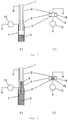
- Fig. 2 a shows a conceptual representation of a first embodiment of a pipetting apparatus according to the present invention.
- the depicted pipette tube 1 is arranged vertically in usage and comprises three sections.
- An upper, first section 2 with an upper opening 5 at the upper end 6 of the pipetting tube 1, to which a suction pump (not shown) is attached in order to provide pressure into the pipette tube 1,
- a lower, second section 3 with a lower opening 7 at the lower end 8 of the pipetting tube 1, through which sample liquid 9 contained in a liquid container 22, such as a sample tube, well or trough, placed on a worktable 21 can be aspirated and/or dispensed.
- An intermediate or middle, third section 4 is located between the upper and lower sections 2, 3.
- the upper and lower sections 2, 3 may not have the same length, so that the intermediate section 4 can be closer to either the upper or lower opening 5, 7.
- a first electrode 10 is arranged at the upper section 2 and a second electrode 11 is arranged at the lower section 3.
- these electrodes 10, 11 are provided at the outer surface of the pipette tube 1, which may for instance be made of glass (or another electrically insulating material). Alternatively, they may be embedded within (the wall of) the pipette tube 1.
- the first and second electrodes 10, 11 thus form a measurement capacitor and are connected to an impedance measurement unit 13.
- FIG. 2 b An equivalent circuit diagram of this first embodiment of the pipetting apparatus is shown in Fig. 2 b) , which depicts the measurement capacitor 12 with the two electrodes 10, 11 and a dielectric 15 located in between.
- the dielectric 15 is formed by (at least part of) the intermediate section 4 together with liquid contained therein.
- the capacity of the measurement capacitor 15 measured by the impedance measurement unit 13 will be dependent on the dielectric 15 and therefore will change in dependence of the amount of liquid located in the intermediate section 4, i.e. will increase as liquid enters into the intermediate section 4. In this way it can easily be determined by measuring the capacity of the measurement capacitor, whether liquid is present in the intermediate section 4.
- a controller can immediately increase the pressure in the pipette tube 1 in order to force out the spilled sample liquid 9 (at least into the lower section 3) or decrease the pressure to suck out spilled system liquid from the intermediate section 4 (at least back into the upper section 2).
- At least part of the upper and/or lower section 2, 3 may be made of a conductor such as metal which form the first and/or second electrode 10, 11.
- Conductive liquid which passes into and through the intermediate section 4, and comes into contact with the electrodes 10, 11 will decrease the resistance measured by the impedance measurement unit 13. Such a decrease in resistance can therefore also indicated that liquid is present within the intermediate section 4.
- Fig. 3 a shows a conceptual representation of a second embodiment of a pipetting apparatus according to the present invention.
- the upper section 2 is made of a first conductive (e.g. metal) tube forming the first electrode, which is connected to ground.
- the lower section is made of a metal (i.e. conductive) mounting fixture such as a cone 3' forming the second electrode, onto which a disposable tip 1' is mounted.
- the second electrode is directly connected to the impedance measurement unit 13, while the first electrode is indirectly connected to the impedance measurement unit 13 via ground.
- the intermediate section 4 is made of an electrically insulating tube, which electrically insulates the first and second electrodes from one another and thus forms part of the dielectric 15 of the measurement capacitor 12.
- the sample liquid 9 will remain in the disposable tip 1' and not come into contact with the cone 3'.
- the cone 3' together with the disposable tip 1' can form a further electrode of a further measurement capacitor, where for instance the worktable, which is e.g. attached to ground, acts as a counter-electrode.
- the measurement capacitor and the further measurement capacitor are connected in parallel with the impedance measurement unit 13, therefore their capacities are added to one another.
- the capacity of the measurement capacitor thus dominates over the capacity of the further measurement capacitor employed for capacitive liquid level detection (cLLD; cf. e.g. Fig. 7 first 15 seconds).
- Fig. 3 b schematically illustrates the arrangement according to the second embodiment in the form of an equivalent circuit diagram.
- the further measurement capacitor is not shown, but would be connected parallel to the measurement capacitor 12 with the impedance measurement unit 13.
- Fig. 4 a shows the second embodiment in the situation where the sample liquid 9 spills into the pipette tube and passes through the intermediate section 4 into the upper section 2.
- the sample liquid 9 is conductive and both the cone 1' as well as the upper section tube are made of metal the resistance of the measurement capacitor 12 will decrease to the point of the sample liquid 9 essentially short circuiting the two electrodes.
- Fig. 4 b) schematically illustrates the corresponding equivalent circuit diagram (for the case of a non-conductive sample liquid, i.e. a situation where the resistance is very large, and thus no parallel resistor is shown).
- Fig. 5 a shows a conceptual representation of a third embodiment of a pipetting apparatus according to the present invention with a porous filter 14 within the intermediate section 4 of the pipette tube 1, i.e. inline within the canal of the pipette tube 1.
- sample liquid 9 or system liquid
- Fig. 5 b schematically illustrates the corresponding equivalent circuit diagram (again for the case of a non-conductive sample liquid, i.e. a situation where the resistance is very large, and thus no parallel resistor is shown).
- Fig. 6 a shows a conceptual representation of a fourth embodiment of a pipetting apparatus according to the present invention with a porous filter 14' is arranged within the disposable tip 1' mounted on the cone 3' of the pipette tube 1.
- the lower end part of the intermediate section 4 axially extends into the upper end part of the cone 3' along the entire length of the inner portion of the cone 3'.
- the filter 14' in the tip 1' is wetted or soaked either by sample liquid 9 or by system liquid 9' the filter 14' is capacitively coupled to the intermediate section 4 by means of the electrical field 16, which results in an increase of the measurement capacitor's capacity.
- Fig. 6 b) schematically illustrates the corresponding equivalent circuit diagram (once again for the case of a non-conductive sample liquid, i.e. a situation where the resistance is very large, and thus no parallel resistor is shown).
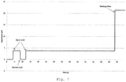
- Fig. 7 shows an exemplary plot of the measured capacity over time for an arrangement according to the third embodiment (cf. Fig. 5 ) with a filter 14 in the intermediate section 4 of the pipette tube 1.
- the tip 1' is removed from the water, resulting in a decrease of the measured total capacity and after 12 seconds re-immersed again, increasing the measured total capacity once more.
- water reaches the porous filter 14, which causes a strong increase of the total capacity due to the permittivity of the dielectric 15 of the measurement capacitor 12 becoming larger because of the sudden influx of water into the filter 14.
- the present invention enables to detect the presence of (sample/system) liquid within an intermediate section 4 of a pipette tube 1.
- a first electrode 10 is arranged at an upper section 2 of the pipette tube 1 (or at least part of the upper section 2 acts as the first electrode 10) and a second electrode 11 is arranged at a lower section 3 of the pipette tube 1 (or at least part of the lower section 2, e.g. the cone 3' onto which a disposable tip 1' can be mounted, acts as the second electrode 11).
- the intermediate section 4 and in particular a porous filter 14 arranged in the canal of the intermediate section 4 acts as a dielectric 15 of a measurement capacitor 12 formed by the two electrodes 10, 11.
- any liquid wetting or soaking the filter 14 will increase the capacity of the measurement capacitor 12 due to the increased permittivity of the dielectric 15 caused by liquid within the filter 14.
- This increase in capacity can be easily detected by means of an impedance measurement unit 13, which can also be used to perform capacitive liquid level detection using a further measurement capacitor attached to the impedance measurement unit 13 parallel to the measurement capacitor 12.
- the detection of liquid within the intermediate section 4 may also be based on a resistance measurement of the measurement capacitor 12 using the impedance measurement unit 13, especially when conductive liquids are to be detected.
Landscapes
- Physics & Mathematics (AREA)
- Chemical & Material Sciences (AREA)
- Health & Medical Sciences (AREA)
- General Physics & Mathematics (AREA)
- Analytical Chemistry (AREA)
- Clinical Laboratory Science (AREA)
- Chemical Kinetics & Catalysis (AREA)
- Pathology (AREA)
- Immunology (AREA)
- General Health & Medical Sciences (AREA)
- Biochemistry (AREA)
- Life Sciences & Earth Sciences (AREA)
- Engineering & Computer Science (AREA)
- Power Engineering (AREA)
- Fluid Mechanics (AREA)
- Thermal Sciences (AREA)
- Electromagnetism (AREA)
- Automatic Analysis And Handling Materials Therefor (AREA)
Priority Applications (4)
| Application Number | Priority Date | Filing Date | Title |
|---|---|---|---|
| EP17210303.8A EP3501654B1 (de) | 2017-12-22 | 2017-12-22 | Pipettiervorrichtung mit einem pipettenrohr und verfahren zur detektion einer flüssigkeit innerhalb eines mittelabschnitts des pipettenrohrs |
| US16/954,793 US11471876B2 (en) | 2017-12-22 | 2018-12-17 | Pipetting apparatus with a pipette tube and method for detecting a liquid within an intermediate section of a pipette tube |
| CN201880083177.9A CN111565848A (zh) | 2017-12-22 | 2018-12-17 | 带有移液管的移液装置和用于检测在移液管的中间段内的液体的方法 |
| PCT/EP2018/085109 WO2019121445A1 (en) | 2017-12-22 | 2018-12-17 | Pipetting apparatus with a pipette tube and method for detecting a liquid within an intermediate section of a pipette tube |
Applications Claiming Priority (1)
| Application Number | Priority Date | Filing Date | Title |
|---|---|---|---|
| EP17210303.8A EP3501654B1 (de) | 2017-12-22 | 2017-12-22 | Pipettiervorrichtung mit einem pipettenrohr und verfahren zur detektion einer flüssigkeit innerhalb eines mittelabschnitts des pipettenrohrs |
Publications (2)
| Publication Number | Publication Date |
|---|---|
| EP3501654A1 true EP3501654A1 (de) | 2019-06-26 |
| EP3501654B1 EP3501654B1 (de) | 2021-08-25 |
Family
ID=60957057
Family Applications (1)
| Application Number | Title | Priority Date | Filing Date |
|---|---|---|---|
| EP17210303.8A Active EP3501654B1 (de) | 2017-12-22 | 2017-12-22 | Pipettiervorrichtung mit einem pipettenrohr und verfahren zur detektion einer flüssigkeit innerhalb eines mittelabschnitts des pipettenrohrs |
Country Status (4)
| Country | Link |
|---|---|
| US (1) | US11471876B2 (de) |
| EP (1) | EP3501654B1 (de) |
| CN (1) | CN111565848A (de) |
| WO (1) | WO2019121445A1 (de) |
Cited By (2)
| Publication number | Priority date | Publication date | Assignee | Title |
|---|---|---|---|---|
| EP3731967A4 (de) * | 2017-12-28 | 2021-01-20 | Formulatrix, Inc. | Pipettenspitze und verfahren zur automatischen aufrechterhaltung der pipettenspitzentiefe in einer flüssigkeit |
| WO2021116408A1 (de) * | 2019-12-12 | 2021-06-17 | Hamilton Bonaduz Ag | Pipettiereinheit mit kapazitiver flüssigkeitsdetektion, kombination einer solchen pipettiereinheit und einer pipettierspitze, und verfahren zum kapazitiven detektieren von pipettierflüssigkeit |
Citations (8)
| Publication number | Priority date | Publication date | Assignee | Title |
|---|---|---|---|---|
| DE9100548U1 (de) * | 1991-01-18 | 1991-04-11 | Kampfrath, Gerit, Dr. | |
| US5045286A (en) * | 1988-02-25 | 1991-09-03 | Olympus Optical Co., Ltd. | Device for aspirating a fixed quantity of liquid |
| US20030049861A1 (en) * | 2001-09-13 | 2003-03-13 | Woodward Roger P. | Dispensing method and apparatus for dispensing very small quantities of fluid |
| US20050095723A1 (en) * | 2003-11-04 | 2005-05-05 | Drummond Scientific Company | Automatic precision non-contact open-loop fluid dispensing |
| US20050279855A1 (en) * | 2004-06-17 | 2005-12-22 | Lemont Baker | Liquid measurements using capacitive monitoring |
| US20060172433A1 (en) * | 2005-01-28 | 2006-08-03 | Arta Motadel | Liquid sampling utilizing ribbed pipette tip for barrier penetration |
| US20130136672A1 (en) * | 2009-10-19 | 2013-05-30 | Eppendorf Ag | Electrically Conductive Pipette Tip |
| US20150114140A1 (en) * | 2013-10-31 | 2015-04-30 | Sysmex Corporation | Method for adjusting position of aspirator and sample processing apparatus |
Family Cites Families (30)
| Publication number | Priority date | Publication date | Assignee | Title |
|---|---|---|---|---|
| JPS58154662A (ja) * | 1982-03-10 | 1983-09-14 | Hitachi Ltd | 前処理機能を備えた自動分析装置 |
| US5212992A (en) * | 1991-06-14 | 1993-05-25 | Medical Laboratory Automation, Inc. | Capacitive probe sensor with reduced effective stray capacitance |
| DE4203638A1 (de) * | 1992-02-08 | 1993-08-12 | Boehringer Mannheim Gmbh | Fluessigkeitstransfereinrichtung fuer ein analysegeraet |
| US5550059A (en) * | 1994-02-23 | 1996-08-27 | Bayer Corporation | Fluid sensing pipette |
| JP3158054B2 (ja) * | 1996-07-19 | 2001-04-23 | 株式会社日立製作所 | 液体採取装置 |
| EP0913671A1 (de) * | 1997-10-29 | 1999-05-06 | Roche Diagnostics GmbH | Verfahren und Vorrichtung zum Flüssigkeitstransfer mit einem Analysegerät |
| CN1127835C (zh) | 1999-04-09 | 2003-11-12 | 通用器材公司 | 有线电话适配器与相连信令控制器之间的密钥管理 |
| DE19919305A1 (de) * | 1999-04-28 | 2000-11-02 | Roche Diagnostics Gmbh | Verfahren und Vorrichtung zum Flüssigkeitstransfer mit einem Analysegerät |
| CA2724266C (en) * | 2000-02-29 | 2012-12-04 | Gen-Probe Incorporated | Fluid dispense and liquid surface verification system and method |
| US20110125050A1 (en) * | 2004-09-21 | 2011-05-26 | The Trustees Of The University Of Pennsylvania | Multiple-Electrode and Metal-Coated Probes |
| DE102005005437A1 (de) * | 2005-02-05 | 2006-08-10 | Eppendorf Ag | Filterpipettenspitze |
| DE102006052833A1 (de) * | 2006-11-09 | 2008-05-15 | Diasys Diagnostic Systems Gmbh | Verfahren zum Feststellen einer Verstopfung, eines Koagels oder eines Pfropfens an der Aufnahmeöffnung einer Dosiernadel |
| JP4966913B2 (ja) * | 2007-05-15 | 2012-07-04 | 株式会社日立ハイテクノロジーズ | 液体分注装置 |
| WO2009001464A1 (ja) * | 2007-06-28 | 2008-12-31 | Olympus Corporation | 洗浄装置、洗浄ノズルの詰り検知方法及び自動分析装置 |
| JP5517467B2 (ja) * | 2009-02-20 | 2014-06-11 | 株式会社日立ハイテクノロジーズ | 自動分析装置 |
| US20120209534A1 (en) * | 2009-10-19 | 2012-08-16 | Yeda Research And Development Co., Ltd. At The Weizmann Institute Of Science | Method and system for analyzing liquid |
| JP5570848B2 (ja) * | 2010-03-05 | 2014-08-13 | 株式会社東芝 | 自動分析装置 |
| JP5600487B2 (ja) * | 2010-06-24 | 2014-10-01 | シスメックス株式会社 | 検体分析装置及び液体吸引方法 |
| EP3035031B1 (de) * | 2010-12-03 | 2022-06-01 | Cellply S.R.L. | Mikroanalyse von zellulären funktionen |
| DK3058337T3 (en) * | 2013-10-15 | 2019-04-15 | Ecole Polytechnique Fed Lausanne Epfl | MEASUREMENT TIP WITH ELECTRIC IMPEDANCE SENSOR |
| EP3086127A4 (de) * | 2013-12-16 | 2017-08-02 | Shimadzu Corporation | Flüssigkeitssammelvorrichtung sowie automatische analysevorrichtung damit |
| CN105829896B (zh) * | 2014-01-07 | 2019-01-22 | 株式会社日立高新技术 | 自动分析装置 |
| EP3120930A4 (de) * | 2014-03-20 | 2017-11-22 | National Institute Of Advanced Industrial Science | Pipettenvorrichtung und flüssigkeitsbehandlungssystem |
| JP6280777B2 (ja) * | 2014-03-24 | 2018-02-14 | シスメックス株式会社 | 分析装置、及び分析装置における液面検出方法 |
| US20180093263A1 (en) * | 2015-04-15 | 2018-04-05 | Ecole Polytechnique Federale De Lausanne (Epfl) | Devices, Systems, and Methods for Dispensing and Analyzing Particles |
| EP3088904A1 (de) * | 2015-04-27 | 2016-11-02 | Siemens Healthcare Diagnostics Products GmbH | Verfahren zur überprüfung der funktionsfähigkeit einer waschstation für pipettiernadeln |
| US11291986B2 (en) * | 2017-02-24 | 2022-04-05 | Becton, Dickinson And Company | Unique sample transfer device for an automated pipettor for processing a variety of clinical microbiological specimens |
| US10910749B2 (en) * | 2017-04-11 | 2021-02-02 | Ecole Polytechnique Federale De Lausanne (Epfl) | Tip connector for fluidic and electrical connection |
| EP3703662A4 (de) * | 2017-11-03 | 2021-12-22 | Mark A. Gray | Herstellung und dosierung von quanten |
| CN116651529A (zh) * | 2017-12-28 | 2023-08-29 | 富默乐有限公司 | 用于自动地保持流体中的吸移管吸头深度的吸移管吸头和方法 |
-
2017
- 2017-12-22 EP EP17210303.8A patent/EP3501654B1/de active Active
-
2018
- 2018-12-17 CN CN201880083177.9A patent/CN111565848A/zh active Pending
- 2018-12-17 US US16/954,793 patent/US11471876B2/en active Active
- 2018-12-17 WO PCT/EP2018/085109 patent/WO2019121445A1/en active Application Filing
Patent Citations (8)
| Publication number | Priority date | Publication date | Assignee | Title |
|---|---|---|---|---|
| US5045286A (en) * | 1988-02-25 | 1991-09-03 | Olympus Optical Co., Ltd. | Device for aspirating a fixed quantity of liquid |
| DE9100548U1 (de) * | 1991-01-18 | 1991-04-11 | Kampfrath, Gerit, Dr. | |
| US20030049861A1 (en) * | 2001-09-13 | 2003-03-13 | Woodward Roger P. | Dispensing method and apparatus for dispensing very small quantities of fluid |
| US20050095723A1 (en) * | 2003-11-04 | 2005-05-05 | Drummond Scientific Company | Automatic precision non-contact open-loop fluid dispensing |
| US20050279855A1 (en) * | 2004-06-17 | 2005-12-22 | Lemont Baker | Liquid measurements using capacitive monitoring |
| US20060172433A1 (en) * | 2005-01-28 | 2006-08-03 | Arta Motadel | Liquid sampling utilizing ribbed pipette tip for barrier penetration |
| US20130136672A1 (en) * | 2009-10-19 | 2013-05-30 | Eppendorf Ag | Electrically Conductive Pipette Tip |
| US20150114140A1 (en) * | 2013-10-31 | 2015-04-30 | Sysmex Corporation | Method for adjusting position of aspirator and sample processing apparatus |
Cited By (2)
| Publication number | Priority date | Publication date | Assignee | Title |
|---|---|---|---|---|
| EP3731967A4 (de) * | 2017-12-28 | 2021-01-20 | Formulatrix, Inc. | Pipettenspitze und verfahren zur automatischen aufrechterhaltung der pipettenspitzentiefe in einer flüssigkeit |
| WO2021116408A1 (de) * | 2019-12-12 | 2021-06-17 | Hamilton Bonaduz Ag | Pipettiereinheit mit kapazitiver flüssigkeitsdetektion, kombination einer solchen pipettiereinheit und einer pipettierspitze, und verfahren zum kapazitiven detektieren von pipettierflüssigkeit |
Also Published As
| Publication number | Publication date |
|---|---|
| US11471876B2 (en) | 2022-10-18 |
| WO2019121445A1 (en) | 2019-06-27 |
| US20210094028A1 (en) | 2021-04-01 |
| EP3501654B1 (de) | 2021-08-25 |
| CN111565848A (zh) | 2020-08-21 |
Similar Documents
| Publication | Publication Date | Title |
|---|---|---|
| CN109414698B (zh) | 具有液体体积传感器和液体处理系统的移液设备 | |
| US8277756B2 (en) | Method of identifying a blockage at the receiving opening of a pipetting needle | |
| JP4373427B2 (ja) | 電気的滴下監視 | |
| US11199433B2 (en) | Method for the automated classification of a liquid as well as method for the automated adaption of presettings for a capacitive liquid level measurement | |
| US11291988B2 (en) | Pipette tip for an automated pipetting device | |
| JPS62218818A (ja) | 自動化学分析装置 | |
| US11471876B2 (en) | Pipetting apparatus with a pipette tube and method for detecting a liquid within an intermediate section of a pipette tube | |
| EP3101432B1 (de) | Automatische analysevorrichtung | |
| JP6563114B2 (ja) | 自動分析装置 | |
| US7207219B2 (en) | Rod-shaped element for liquid level detection and corresponding device for liquid level detection | |
| EP4202443A1 (de) | Verfahren und vorrichtung zur erfassung des kontakts einer pipettenspitze mit einer flüssigkeit sowie ein laborsystem mit einer solchen vorrichtung | |
| EP4187254A1 (de) | Lecktest | |
| JP2009281877A (ja) | 分注装置 |
Legal Events
| Date | Code | Title | Description |
|---|---|---|---|
| PUAI | Public reference made under article 153(3) epc to a published international application that has entered the european phase |
Free format text: ORIGINAL CODE: 0009012 |
|
| STAA | Information on the status of an ep patent application or granted ep patent |
Free format text: STATUS: THE APPLICATION HAS BEEN PUBLISHED |
|
| AK | Designated contracting states |
Kind code of ref document: A1 Designated state(s): AL AT BE BG CH CY CZ DE DK EE ES FI FR GB GR HR HU IE IS IT LI LT LU LV MC MK MT NL NO PL PT RO RS SE SI SK SM TR |
|
| AX | Request for extension of the european patent |
Extension state: BA ME |
|
| STAA | Information on the status of an ep patent application or granted ep patent |
Free format text: STATUS: REQUEST FOR EXAMINATION WAS MADE |
|
| 17P | Request for examination filed |
Effective date: 20191219 |
|
| RBV | Designated contracting states (corrected) |
Designated state(s): AL AT BE BG CH CY CZ DE DK EE ES FI FR GB GR HR HU IE IS IT LI LT LU LV MC MK MT NL NO PL PT RO RS SE SI SK SM TR |
|
| STAA | Information on the status of an ep patent application or granted ep patent |
Free format text: STATUS: EXAMINATION IS IN PROGRESS |
|
| 17Q | First examination report despatched |
Effective date: 20200212 |
|
| STAA | Information on the status of an ep patent application or granted ep patent |
Free format text: STATUS: EXAMINATION IS IN PROGRESS |
|
| GRAP | Despatch of communication of intention to grant a patent |
Free format text: ORIGINAL CODE: EPIDOSNIGR1 |
|
| STAA | Information on the status of an ep patent application or granted ep patent |
Free format text: STATUS: GRANT OF PATENT IS INTENDED |
|
| INTG | Intention to grant announced |
Effective date: 20210329 |
|
| GRAJ | Information related to disapproval of communication of intention to grant by the applicant or resumption of examination proceedings by the epo deleted |
Free format text: ORIGINAL CODE: EPIDOSDIGR1 |
|
| STAA | Information on the status of an ep patent application or granted ep patent |
Free format text: STATUS: EXAMINATION IS IN PROGRESS |
|
| GRAP | Despatch of communication of intention to grant a patent |
Free format text: ORIGINAL CODE: EPIDOSNIGR1 |
|
| STAA | Information on the status of an ep patent application or granted ep patent |
Free format text: STATUS: GRANT OF PATENT IS INTENDED |
|
| INTC | Intention to grant announced (deleted) | ||
| INTG | Intention to grant announced |
Effective date: 20210607 |
|
| GRAS | Grant fee paid |
Free format text: ORIGINAL CODE: EPIDOSNIGR3 |
|
| GRAA | (expected) grant |
Free format text: ORIGINAL CODE: 0009210 |
|
| STAA | Information on the status of an ep patent application or granted ep patent |
Free format text: STATUS: THE PATENT HAS BEEN GRANTED |
|
| AK | Designated contracting states |
Kind code of ref document: B1 Designated state(s): AL AT BE BG CH CY CZ DE DK EE ES FI FR GB GR HR HU IE IS IT LI LT LU LV MC MK MT NL NO PL PT RO RS SE SI SK SM TR |
|
| REG | Reference to a national code |
Ref country code: CH Ref legal event code: EP |
|
| REG | Reference to a national code |
Ref country code: IE Ref legal event code: FG4D Ref country code: AT Ref legal event code: REF Ref document number: 1423241 Country of ref document: AT Kind code of ref document: T Effective date: 20210915 |
|
| REG | Reference to a national code |
Ref country code: DE Ref legal event code: R096 Ref document number: 602017044640 Country of ref document: DE |
|
| REG | Reference to a national code |
Ref country code: LT Ref legal event code: MG9D |
|
| REG | Reference to a national code |
Ref country code: NL Ref legal event code: MP Effective date: 20210825 |
|
| REG | Reference to a national code |
Ref country code: AT Ref legal event code: MK05 Ref document number: 1423241 Country of ref document: AT Kind code of ref document: T Effective date: 20210825 |
|
| PG25 | Lapsed in a contracting state [announced via postgrant information from national office to epo] |
Ref country code: RS Free format text: LAPSE BECAUSE OF FAILURE TO SUBMIT A TRANSLATION OF THE DESCRIPTION OR TO PAY THE FEE WITHIN THE PRESCRIBED TIME-LIMIT Effective date: 20210825 Ref country code: SE Free format text: LAPSE BECAUSE OF FAILURE TO SUBMIT A TRANSLATION OF THE DESCRIPTION OR TO PAY THE FEE WITHIN THE PRESCRIBED TIME-LIMIT Effective date: 20210825 Ref country code: HR Free format text: LAPSE BECAUSE OF FAILURE TO SUBMIT A TRANSLATION OF THE DESCRIPTION OR TO PAY THE FEE WITHIN THE PRESCRIBED TIME-LIMIT Effective date: 20210825 Ref country code: PT Free format text: LAPSE BECAUSE OF FAILURE TO SUBMIT A TRANSLATION OF THE DESCRIPTION OR TO PAY THE FEE WITHIN THE PRESCRIBED TIME-LIMIT Effective date: 20211227 Ref country code: NO Free format text: LAPSE BECAUSE OF FAILURE TO SUBMIT A TRANSLATION OF THE DESCRIPTION OR TO PAY THE FEE WITHIN THE PRESCRIBED TIME-LIMIT Effective date: 20211125 Ref country code: FI Free format text: LAPSE BECAUSE OF FAILURE TO SUBMIT A TRANSLATION OF THE DESCRIPTION OR TO PAY THE FEE WITHIN THE PRESCRIBED TIME-LIMIT Effective date: 20210825 Ref country code: ES Free format text: LAPSE BECAUSE OF FAILURE TO SUBMIT A TRANSLATION OF THE DESCRIPTION OR TO PAY THE FEE WITHIN THE PRESCRIBED TIME-LIMIT Effective date: 20210825 Ref country code: AT Free format text: LAPSE BECAUSE OF FAILURE TO SUBMIT A TRANSLATION OF THE DESCRIPTION OR TO PAY THE FEE WITHIN THE PRESCRIBED TIME-LIMIT Effective date: 20210825 Ref country code: BG Free format text: LAPSE BECAUSE OF FAILURE TO SUBMIT A TRANSLATION OF THE DESCRIPTION OR TO PAY THE FEE WITHIN THE PRESCRIBED TIME-LIMIT Effective date: 20211125 Ref country code: LT Free format text: LAPSE BECAUSE OF FAILURE TO SUBMIT A TRANSLATION OF THE DESCRIPTION OR TO PAY THE FEE WITHIN THE PRESCRIBED TIME-LIMIT Effective date: 20210825 |
|
| PG25 | Lapsed in a contracting state [announced via postgrant information from national office to epo] |
Ref country code: PL Free format text: LAPSE BECAUSE OF FAILURE TO SUBMIT A TRANSLATION OF THE DESCRIPTION OR TO PAY THE FEE WITHIN THE PRESCRIBED TIME-LIMIT Effective date: 20210825 Ref country code: LV Free format text: LAPSE BECAUSE OF FAILURE TO SUBMIT A TRANSLATION OF THE DESCRIPTION OR TO PAY THE FEE WITHIN THE PRESCRIBED TIME-LIMIT Effective date: 20210825 Ref country code: GR Free format text: LAPSE BECAUSE OF FAILURE TO SUBMIT A TRANSLATION OF THE DESCRIPTION OR TO PAY THE FEE WITHIN THE PRESCRIBED TIME-LIMIT Effective date: 20211126 |
|
| PG25 | Lapsed in a contracting state [announced via postgrant information from national office to epo] |
Ref country code: NL Free format text: LAPSE BECAUSE OF FAILURE TO SUBMIT A TRANSLATION OF THE DESCRIPTION OR TO PAY THE FEE WITHIN THE PRESCRIBED TIME-LIMIT Effective date: 20210825 |
|
| PG25 | Lapsed in a contracting state [announced via postgrant information from national office to epo] |
Ref country code: DK Free format text: LAPSE BECAUSE OF FAILURE TO SUBMIT A TRANSLATION OF THE DESCRIPTION OR TO PAY THE FEE WITHIN THE PRESCRIBED TIME-LIMIT Effective date: 20210825 |
|
| REG | Reference to a national code |
Ref country code: DE Ref legal event code: R097 Ref document number: 602017044640 Country of ref document: DE |
|
| PG25 | Lapsed in a contracting state [announced via postgrant information from national office to epo] |
Ref country code: SM Free format text: LAPSE BECAUSE OF FAILURE TO SUBMIT A TRANSLATION OF THE DESCRIPTION OR TO PAY THE FEE WITHIN THE PRESCRIBED TIME-LIMIT Effective date: 20210825 Ref country code: SK Free format text: LAPSE BECAUSE OF FAILURE TO SUBMIT A TRANSLATION OF THE DESCRIPTION OR TO PAY THE FEE WITHIN THE PRESCRIBED TIME-LIMIT Effective date: 20210825 Ref country code: RO Free format text: LAPSE BECAUSE OF FAILURE TO SUBMIT A TRANSLATION OF THE DESCRIPTION OR TO PAY THE FEE WITHIN THE PRESCRIBED TIME-LIMIT Effective date: 20210825 Ref country code: EE Free format text: LAPSE BECAUSE OF FAILURE TO SUBMIT A TRANSLATION OF THE DESCRIPTION OR TO PAY THE FEE WITHIN THE PRESCRIBED TIME-LIMIT Effective date: 20210825 Ref country code: CZ Free format text: LAPSE BECAUSE OF FAILURE TO SUBMIT A TRANSLATION OF THE DESCRIPTION OR TO PAY THE FEE WITHIN THE PRESCRIBED TIME-LIMIT Effective date: 20210825 Ref country code: AL Free format text: LAPSE BECAUSE OF FAILURE TO SUBMIT A TRANSLATION OF THE DESCRIPTION OR TO PAY THE FEE WITHIN THE PRESCRIBED TIME-LIMIT Effective date: 20210825 |
|
| PLBE | No opposition filed within time limit |
Free format text: ORIGINAL CODE: 0009261 |
|
| STAA | Information on the status of an ep patent application or granted ep patent |
Free format text: STATUS: NO OPPOSITION FILED WITHIN TIME LIMIT |
|
| PG25 | Lapsed in a contracting state [announced via postgrant information from national office to epo] |
Ref country code: MC Free format text: LAPSE BECAUSE OF FAILURE TO SUBMIT A TRANSLATION OF THE DESCRIPTION OR TO PAY THE FEE WITHIN THE PRESCRIBED TIME-LIMIT Effective date: 20210825 Ref country code: IT Free format text: LAPSE BECAUSE OF FAILURE TO SUBMIT A TRANSLATION OF THE DESCRIPTION OR TO PAY THE FEE WITHIN THE PRESCRIBED TIME-LIMIT Effective date: 20210825 |
|
| 26N | No opposition filed |
Effective date: 20220527 |
|
| PG25 | Lapsed in a contracting state [announced via postgrant information from national office to epo] |
Ref country code: SI Free format text: LAPSE BECAUSE OF FAILURE TO SUBMIT A TRANSLATION OF THE DESCRIPTION OR TO PAY THE FEE WITHIN THE PRESCRIBED TIME-LIMIT Effective date: 20210825 |
|
| REG | Reference to a national code |
Ref country code: BE Ref legal event code: MM Effective date: 20211231 |
|
| PG25 | Lapsed in a contracting state [announced via postgrant information from national office to epo] |
Ref country code: LU Free format text: LAPSE BECAUSE OF NON-PAYMENT OF DUE FEES Effective date: 20211222 Ref country code: IE Free format text: LAPSE BECAUSE OF NON-PAYMENT OF DUE FEES Effective date: 20211222 |
|
| PG25 | Lapsed in a contracting state [announced via postgrant information from national office to epo] |
Ref country code: BE Free format text: LAPSE BECAUSE OF NON-PAYMENT OF DUE FEES Effective date: 20211231 |
|
| P01 | Opt-out of the competence of the unified patent court (upc) registered |
Effective date: 20230522 |
|
| PG25 | Lapsed in a contracting state [announced via postgrant information from national office to epo] |
Ref country code: CY Free format text: LAPSE BECAUSE OF FAILURE TO SUBMIT A TRANSLATION OF THE DESCRIPTION OR TO PAY THE FEE WITHIN THE PRESCRIBED TIME-LIMIT Effective date: 20210825 |
|
| PG25 | Lapsed in a contracting state [announced via postgrant information from national office to epo] |
Ref country code: HU Free format text: LAPSE BECAUSE OF FAILURE TO SUBMIT A TRANSLATION OF THE DESCRIPTION OR TO PAY THE FEE WITHIN THE PRESCRIBED TIME-LIMIT; INVALID AB INITIO Effective date: 20171222 |
|
| PGFP | Annual fee paid to national office [announced via postgrant information from national office to epo] |
Ref country code: GB Payment date: 20231102 Year of fee payment: 7 |
|
| PGFP | Annual fee paid to national office [announced via postgrant information from national office to epo] |
Ref country code: FR Payment date: 20231108 Year of fee payment: 7 Ref country code: DE Payment date: 20231031 Year of fee payment: 7 |
|
| PG25 | Lapsed in a contracting state [announced via postgrant information from national office to epo] |
Ref country code: MK Free format text: LAPSE BECAUSE OF FAILURE TO SUBMIT A TRANSLATION OF THE DESCRIPTION OR TO PAY THE FEE WITHIN THE PRESCRIBED TIME-LIMIT Effective date: 20210825 |
|
| PGFP | Annual fee paid to national office [announced via postgrant information from national office to epo] |
Ref country code: CH Payment date: 20240101 Year of fee payment: 7 |