EP3501254A1 - Erntevorsatz mit einem mulchgerät zur bearbeitung von auf einem feld stehenden pflanzenstümpfen - Google Patents
Erntevorsatz mit einem mulchgerät zur bearbeitung von auf einem feld stehenden pflanzenstümpfen Download PDFInfo
- Publication number
- EP3501254A1 EP3501254A1 EP18213105.2A EP18213105A EP3501254A1 EP 3501254 A1 EP3501254 A1 EP 3501254A1 EP 18213105 A EP18213105 A EP 18213105A EP 3501254 A1 EP3501254 A1 EP 3501254A1
- Authority
- EP
- European Patent Office
- Prior art keywords
- harvesting
- frame
- field
- mulching device
- side parts
- Prior art date
- Legal status (The legal status is an assumption and is not a legal conclusion. Google has not performed a legal analysis and makes no representation as to the accuracy of the status listed.)
- Granted
Links
Images
Classifications
-
- A—HUMAN NECESSITIES
- A01—AGRICULTURE; FORESTRY; ANIMAL HUSBANDRY; HUNTING; TRAPPING; FISHING
- A01D—HARVESTING; MOWING
- A01D34/00—Mowers; Mowing apparatus of harvesters
- A01D34/835—Mowers; Mowing apparatus of harvesters specially adapted for particular purposes
- A01D34/8355—Mowers; Mowing apparatus of harvesters specially adapted for particular purposes for cutting up or crushing remaining standing stalks, e.g. stubble
Definitions
- the invention relates to a header which is a supporting frame which is movable in a forward direction over a field, one or more mounted on the frame harvest units for harvesting stalk-like plants and at least one mounted on the frame mulcher for crushing and / or defibration of the after harvest on
- the plant stumps remaining in the field can be moved by means of an actuator relative to the frame between a lowered operating position and a raised non-operating position.
- Such mulchers are usually articulated freely pivotable about the transverse axis on the frame of the header and are supported by runners on the ground, so that they are performed Bodenenkopf near the ground to crush the stalks near the bottom (see, for example WO 2014/012620 A1 ), or they are connected by a parallelogram with the header and are lifted when not in use by an actuator ( DE 603 13 399 T2 ) or the actuator is blocked while maneuvering the harvester and the header lifted ( EP 3 155 888 A1 ).
- the present invention has set itself the goal of providing a crop header that is improved over the prior art.
- a header comprises a supporting frame which is movable in a forward direction over a field, one or more mounted on the frame harvest units for harvesting stalk-like plants and at least one mounted on the frame mulcher for crushing and / or defibration of the remaining after harvest on the field plant stumps , which is movable by means of an actuator relative to the frame between a lowered operating position and a raised non-operating position.
- a protective element is mounted, which extends at least over the width of the mulching device, rigidly connected to the frame and arranged in the vertical direction deeper than the mulching device located in the raised inoperative position.
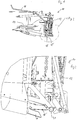
- FIG. 1 shows a side view of a harvest header for corn crop. It comprises a carrying frame 12, in particular designed as a frame construction, which can be attached to a feed channel of a harvesting machine (forage harvester) and carries a number of mowing and collecting drums 14 which are used to harvest complete, stalk-like plants (eg maize). While in the harvesting operation, in which the header 10 in a forward direction, the in the Figures 1 and 2 runs to the left, is moved over a field, the cut plants are promoted in the intake duct of the harvester, the plant stumps remain with their roots in the ground. Printhead clips 16 are used to push the plants slightly forward in order to be able to cut them off better.
- header 10 is in the DE 103 51 858 A1 the disclosure of which is incorporated herein by reference.
- the header 10 could have instead of mowing and recovery drums chain conveyor for cutting and picking up the plants or be designed as a corn picker for a combine harvester.
- the mulching devices are movable by an actuator, not shown, between a lowered operating position, in which they are identified by the reference numeral 18, and a raised inoperative position, in which they are designated by the reference numeral 18 ', ie at its front end on the supporting frame 12th around a transverse direction (perpendicular to the plane of the Figures 1 and 2 ) extending axis pivoted.
- Possible embodiments of the mulching devices 18 are in the DE 10 2016 213 260 A1 shown and the DE 10 2017 222 587 A1 describes a suitable actuator and its control in more detail.
- the actuator spends mulching device 18 'into the inoperative position at least when it is not needed (eg when maneuvering or reversing on the field or when the harvester is stationary).
- the harvesting attachment 10 comprises a number of a total of eight mulching devices 18 which are positioned in the lateral direction at least in each case where, as expected, the crop rows to be harvested arrive at the mowing and drawing drums 14.
- a number of protective elements 20 are attached at a relatively small distance of, for example, a few cm immediately to the rear of the mulching devices 18.
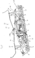
- the protective elements 20 extend at least across the width of the upstream mulcher 18, are rigidly connected to the supporting frame 12 and its lower edge in the vertical direction is lower than (or in the same level as) the lower edge of the mulching device 18 in the raised inoperative position 'arranged. Note that the mulching devices 18 in the FIG. 3 are shown in the lowered operating position and therefore lower than the protective elements 20 are, while they are higher than the protective elements 20 in the inoperative position.
- a total of three protective elements 18 are provided, each approximately over the entire width of a central portion 22 and a liftable from the crop position shown in a road driving position side part 24 of the Header 10 extend.
- the middle part 22 carries two mowing and retraction drums 14 and the outer parts 24 each have a mowing and catching drum 14.
- the number and size of the mowing and retracting drums 14 and also the mulching devices 18 may deviate therefrom.
- the protective elements 20 are rigidly connected rigidly to the supporting frame 12 of the middle part 22 or side part 24.
- the protective elements 20 are designed as tubes, but could also be solid.
- the cross section of the protective elements 20 is circular, but could also have any other shape.
- struts 26 each adjacent to one end of the protective element 20 in pairs (two edges of a triangular pyramid forming) obliquely upwards and forwards and to the side and meet on the supporting frame 12
- additional arms 28 are arranged, which extend starting from the rear, lower end of the strut 26 in pairs obliquely upwards and forwards and to the side and meet on the rear wall of the supporting frame 12.
- the arms 28 may be coupled to the struts 26 on the header 10 side by vertical connections 30.
- the struts 26, connections 30 and arms 28 may be formed as profile or deep drawn parts or by a welded tube construction. At holes of the connections 30, the connection to the rear wall of the supporting frame 12 of the side member 24 and a there existing, supporting element of the frame 12 can be done, including in particular screws and nuts can be provided.
- connection of the protective element 20 at the middle part 22 is effected by welded sheet metal elements 32, which establish connections with suitable parts of the supporting frame 12. In the harvesting position, a positive connection between the protective element 20 of the middle part and the protective elements 20 of the outer parts 24 could be produced.
- the protective elements 20 is in the event that the harvester should sink into the field and back again pulled out of the non-viable area of the field or out of its own power back out, prevents that (then standing at a stand harvester by a control or spent after an operator input by the actuators in the inoperative position) mulchers 18 are damaged.
- the protective elements 20 do not disturb the operation. The same applies if the mulchers 18 are in the harvesting operation or driving on the road in the inoperative position.
- FIG. 1 A block diagram illustrating an exemplary embodiment of the side parts.
- FIG. 1 A block diagram illustrating an exemplary embodiment of the side parts.
- FIG. 1 A block diagram illustrating an exemplary embodiment of the side parts.
- FIG. 1 A block diagram illustrating an exemplary embodiment of the side parts.
- FIG. 1 A block diagram illustrating an exemplary embodiment of the side parts.
- FIG. 1 A block diagram illustrating an exemplary embodiment of the side parts.
Landscapes
- Life Sciences & Earth Sciences (AREA)
- Environmental Sciences (AREA)
- Harvester Elements (AREA)
- Harvesting Machines For Specific Crops (AREA)
Abstract
Description
- Die Erfindung betrifft einen Erntevorsatz, der ein tragendes Gestell, das in einer Vorwärtsrichtung über ein Feld bewegbar ist, eine oder mehrere am Gestell angebrachte Ernteeinheiten zur Ernte stängelartiger Pflanzen und mindestens ein am Gestell angebrachtes Mulchgerät zur Zerkleinerung und/oder Zerfaserung der nach der Ernte auf dem Feld verbleibenden Pflanzenstümpfe umfasst, das mittels eines Aktors gegenüber dem Gestell zwischen einer abgesenkten Betriebsposition und einer angehobenen Außerbetriebsposition beweglich ist.
- Unterhalb von Erntevorsätzen zur Maisernte werden in vielen Fällen (auch als Stängelhäcksler bezeichnete) Mulchgeräte zur Zerkleinerung und/oder Zerfaserung der nach der Ernte auf dem Feld verbleibenden Pflanzenstümpfe angebracht, sei es zur Schonung der Reifen der auf dem Feld fahrenden Fahrzeuge, zur Verbesserung der Verrottung der Pflanzenreste oder zur Vernichtung des Überwinterungsraumes des Maiszünslers (Ostrinia nubilalis).
- Derartige Mulchgeräte werden üblicherweise um die Querachse frei schwenkbar am Rahmen des Erntevorsatzes angelenkt und stützen sich durch Kufen am Boden ab, sodass sie bodenkopierend in Bodennähe geführt werden, um die Stängel in Bodennähe zu zerkleinern (s. beispielsweise
WO 2014/012620 A1 ), oder sie sind durch eine Parallelogrammführung mit dem Erntevorsatz verbunden und werden bei Nichtbenutzung durch einen Aktor ausgehoben (DE 603 13 399 T2 ) oder der Aktor wird beim Rangieren der Erntemaschine in sich blockiert und der Erntevorsatz ausgehoben (EP 3 155 888 A1 ). - Es sind Betriebssituationen der Erntemaschine denkbar, bei denen das Mulchgerät gefährdet ist. Hierzu zählt beispielsweise der Fall, dass die Vorderräder der Erntemaschine in feuchtem Boden einsinken. In diesem Fall dringt auch das Mulchgerät in den Boden ein. Wird die Erntemaschine anschließend aus eigener Kraft oder durch eine andere Maschine aus dem Boden gezogen, was üblicherweise in der Rückwärtsrichtung erfolgt, verhakt sich das Mulchgerät im Boden und wird verbogen.
- Die vorliegende Erfindung hat sich zum Ziel gesetzt, einen gegenüber dem Stand der Technik verbesserten Erntevorsatz bereitzustellen.
- Diese Aufgabe wird erfindungsgemäß durch die Lehre des Patentanspruchs 1 gelöst.
- Ein Erntevorsatz umfasst ein tragendes Gestell, das in einer Vorwärtsrichtung über ein Feld bewegbar ist, eine oder mehrere am Gestell angebrachte Ernteeinheiten zur Ernte stängelartiger Pflanzen und mindestens ein am Gestell angebrachtes Mulchgerät zur Zerkleinerung und/oder Zerfaserung der nach der Ernte auf dem Feld verbleibenden Pflanzenstümpfe, das mittels eines Aktors gegenüber dem Gestell zwischen einer abgesenkten Betriebsposition und einer angehobenen Außerbetriebsposition beweglich ist. Rückwärtig des Mulchgeräts ist ein Schutzelement angebracht, das sich zumindest über die Breite des Mulchgeräts erstreckt, starr mit dem Gestell verbunden und in vertikaler Richtung tiefer als das in der angehobenen Außerbetriebsposition befindliche Mulchgerät angeordnet ist.
- Auf diese Weise vermeidet man, dass das Mulchgerät beim Herausziehen der Erntemaschine aus feuchtem Boden beschädigt wird, denn das Schutzelement schiebt in diesem Fall die Erde vor sich her, in die sich das Mulchgerät ohne das Schutzelement eingraben würde.
- In den Zeichnungen wird ein nachfolgend näher beschriebenes Ausführungsbeispiel dargestellt. Es zeigen:
- Fig. 1
- eine Seitenansicht eines Erntevorsatzes zur Maisernte,
- Fig. 2
- eine vergrößerte Seitenansicht des Erntevorsatzes, und
- Fig. 3
- eine perspektivische, rückwärtige Ansicht des Erntevorsatzes der
Figur 1 . - Die
Figur 1 zeigt eine seitliche Ansicht eines Erntevorsatzes zur Maisernte. Er umfasst ein insbesondere als Rahmenkonstruktion ausgeführtes, tragendes Gestell 12, das an einem Einzugskanal einer Erntemaschine (Feldhäcksler) anbringbar ist und eine Anzahl an Mäh- und Einzugstrommeln 14 trägt, die zur Ernte vollständiger, stängelartiger Pflanzen (z.B. Mais) dienen. Während im Erntebetrieb, in dem der Erntevorsatz 10 in einer Vorwärtsrichtung, die in denFiguren 1 und 2 nach links verläuft, über ein Feld bewegt wird, die abgeschnittenen Pflanzen in den Einzugskanal der Erntemaschine gefördert werden, verbleiben die Pflanzenstümpfe mit ihren Wurzeln im Erdboden. Vordruckbügel 16 dienen dazu, die Pflanzen etwas nach vorn zu drücken, um sie besser abschneiden zu können. Ein ähnlicher Erntevorsatz 10 ist in derDE 103 51 858 A1 beschrieben, deren Offenbarung durch Verweis mit in die vorliegenden Unterlagen aufgenommen wird. Der Erntevorsatz 10 könnte anstelle von Mäh-und Einzugstrommeln Kettenförderer zum Abschneiden und Aufnehmen der Pflanzen aufweisen oder als Maispflücker für einen Mähdrescher ausgeführt sein. - Unterhalb des tragenden Gestells 12 sind, wie insbesondere in der
Figur 2 erkennbar, eine Anzahl an Mulchgeräten 18 über die Breite des Erntevorsatzes 10 verteilt. Die Mulchgeräte sind durch einen nicht gezeigten Aktor zwischen einer abgesenkten Betriebsstellung, in der sie mit dem Bezugszeichen 18 gekennzeichnet sind, und einer angehobenen Außerbetriebsstellung, in der sie mit dem Bezugszeichen 18' gekennzeichnet sind, beweglich, d.h. an ihrem vorderen Ende am tragenden Gestell 12 um eine sich in Querrichtung (senkrecht zur Zeichenebene derFiguren 1 und 2 ) erstreckende Achse schwenkbar angelenkt. Mögliche Ausführungsformen der Mulchgeräte 18 sind in derDE 10 2016 213 260 A1 gezeigt und dieDE 10 2017 222 587 A1 beschreibt einen geeigneten Aktor und dessen Ansteuerung genauer. Der Inhalt beider Schriften wird durch Verweis mit in die vorliegenden Unterlagen aufgenommen. Der Aktor verbringt das Mulchgerät 18' zumindest dann in die Außerbetriebsposition, wenn es nicht benötigt wird (z.B. beim Rangieren oder Rückwärtsfahren auf dem Feld oder wenn die Erntemaschine stillsteht). Der Erntevorsatz 10 umfasst eine Anzahl von insgesamt acht Mulchgeräten 18, die in seitlicher Richtung zumindest jeweils dort positioniert sind, wo an den Mäh- und Einzugstrommeln 14 jeweils erwartungsgemäß die zu erntenden Pflanzenreihen einlaufen. - Eine Anzahl an Schutzelementen 20 ist mit einem relativ geringen Abstand von z.B. einigen cm unmittelbar rückwärtig der Mulchgeräte 18 angebracht. Die Schutzelemente 20 erstrecken sich zumindest über die Breite des ihnen jeweils vorgelagerten Mulchgeräts 18, sind starr mit dem tragenden Gestell 12 verbunden und ihre Unterkante ist in vertikaler Richtung tiefer als (oder in derselben Höhenebene wie) die Unterkante des in der angehobenen Außerbetriebsposition befindlichen Mulchgeräts 18' angeordnet. Man beachte, dass die Mulchgeräte 18 in der
Figur 3 in der abgesenkten Betriebsposition gezeigt sind und daher tiefer als die Schutzelemente 20 liegen, während sie in der Außerbetriebsposition höher als die Schutzelemente 20 sind. Es sind in der dargestellten Ausführungsform insgesamt drei Schutzelemente 18 vorhanden, die sich jeweils näherungsweise über die gesamte Breite eines Mittelteils 22 bzw. eines aus der dargestellten Ernteposition in eine Straßenfahrposition anhebbaren Seitenteils 24 des Erntevorsatzes 10 erstrecken. Der Mittelteil 22 trägt zwei Mäh- und Einzugstrommeln 14 und die Außenteile 24 jeweils eine Mäh- und Einzugstrommel 14. Bei anderen Ausführungsformen kann die Anzahl und Größe der Mäh- und Einzugstrommeln 14 und auch der Mulchgeräte 18 hiervon abweichen. - Die Schutzelemente 20 sind starr mit dem tragenden Gestell 12 des Mittelteils 22 bzw. Seitenteils 24 starr verbunden. Die Schutzelemente 20 sind als Rohre ausgeführt, könnten jedoch auch massiv sein. Der Querschnitt der Schutzelemente 20 ist kreisförmig, könnte aber auch eine beliebige andere Form haben.
- Zur Anbringung der Schutzelemente 20 am tragenden Gestell 12 dienen bei den Seitenteilen 24 Streben 26, die jeweils einem Ende der Schutzelementes 20 benachbart sich paarweise (zwei Kanten einer Dreieckspyramide bildend) schräg nach oben und vorn und zur Seite erstrecken und sich am tragenden Gestell 12 treffen. Unterhalb der Streben 26 sind zusätzliche Arme 28 angeordnet, die ausgehend vom rückwärtigen, unteren Ende der Strebe 26 sich paarweise schräg nach oben und vorn und zur Seite erstrecken und sich an der Rückwand des tragenden Gestells 12 treffen. Die Arme 28 können auf der Seite des Erntevorsatzes 10 durch vertikale Verbindungen 30 mit den Streben 26 gekoppelt sein. Die Streben 26, Verbindungen 30 und Arme 28 können als Profil- oder Tiefziehteile oder durch eine geschweißte Rohrkonstruktion gebildet sein. An Löchern der Verbindungen 30 kann die Anbindung an der Rückwand des tragenden Gestells 12 des Seitenteils 24 bzw. einem dort vorhandenen, tragenden Element des Gestells 12 erfolgen, wozu insbesondere Schrauben und Muttern vorgesehen werden können.
- Die Anbindung des Schutzelementes 20 am Mittelteil 22 erfolgt durch angeschweißte Blechelemente 32, die Verbindungen mit geeigneten Teilen des tragenden Gestells 12 herstellen. In der Ernteposition könnte ein Formschluss zwischen dem Schutzelement 20 des Mittelteils und den Schutzelementen 20 der Außenteile 24 hergestellt werden.
- Durch die Schutzelemente 20 wird in dem Fall, dass die Erntemaschine im Feld einsinken sollte und rückwärts wieder aus dem nicht tragfähigen Bereich des Feldes herausgezogen wird oder aus eigener Kraft rückwärts daraus hinaus fährt, verhindert dass die (dann bei stehender Erntemaschine durch eine Steuerung selbsttätig oder nach einer Bedienereingabe durch die Aktoren in die Außerbetriebsposition verbrachten) Mulchgeräte 18 beschädigt werden. Befindet sich das Mulchgerät 18 hingegen beim Erntebetrieb in der Betriebsposition 18, stören die Schutzelemente 20 den Betrieb nicht. Gleiches gilt, wenn die Mulchgeräte 18 beim Erntebetrieb oder bei Straßenfahrt in der Außerbetriebsposition sind.
- Es sei noch angemerkt, dass in einer anderen Ausführungsform an den äußeren Enden der Seitenteile noch weitere Seitenteile angelenkt werden können, die ebenfalls mit Schutzelementen 20 ausgestattet werden können. Die Mulchgeräte 18 können, wie dargestellt, um die Querachse pendelnd angebracht sein, oder sie sind linear entlang einer Geraden oder an Parallelogrammhalterungen entlang einer Kurve höhenbeweglich. Generell benötigen alle schleppend an einem Erntevorsatz oder einem anderen Arbeitsgerät angebrachten Mulchgeräte 18 rückwärtige Schutzelemente 20, damit sie bei Rückwärtsfahrt in der angehobenen Position verbleiben.
Claims (4)
- Erntevorsatz (10), umfassend ein tragendes Gestell (12), das in einer Vorwärtsrichtung über ein Feld bewegbar ist, eine oder mehrere am Gestell (12) angebrachte Ernteeinheiten zur Ernte stängelartiger Pflanzen und mindestens ein am Gestell (12) angebrachtes Mulchgerät (18) zur Zerkleinerung und/oder Zerfaserung der nach der Ernte auf dem Feld verbleibenden Pflanzenstümpfe, das mittels eines Aktors gegenüber dem Gestell (12) zwischen einer abgesenkten Betriebsposition (18) und einer angehobenen Außerbetriebsposition (18') beweglich ist, dadurch gekennzeichnet, dass rückwärtig des Mulchgeräts (18) ein Schutzelement (20) angebracht ist, das sich zumindest über die Breite des Mulchgeräts (20) erstreckt, starr mit dem Gestell (12) verbunden und in vertikaler Richtung tiefer als das in der angehobenen Außerbetriebsposition (18') befindliche Mulchgerät (18) angeordnet ist.
- Erntevorsatz (10) nach Anspruch 1, wobei das tragende Gestell (12) einen Mittelteil (22) und zwei Seitenteile (24) umfasst, die aus einer Ernteposition in eine Straßentransportposition verbringbar sind und am Mittelteil (22) und an den Seitenteilen (24) jeweils eine oder mehrere Mäh- und Einzugstrommeln (14) als Ernteeinheit angebracht sind und Mulchgeräte (18) sowie Schutzelemente (20) am Mittelteil (22) und an den Seitenteilen (24) angebracht sind, die sich jeweils zumindest näherungsweise über die Breite des Mittelteils (22) bzw. Seitenteils (24) erstrecken.
- Erntevorsatz (10) nach Anspruch 2, wobei die Schutzelemente (20) an den Seitenteilen (24) durch in der Nähe der Enden des Schutzelements (20) des Seitenteils (24) angebrachte Streben (26) befestigt sind, die sich paarweise nach vorn und oben und seitlich erstrecken und an der Rückwand des Seitenteils (24) zusammentreffen.
- Erntevorsatz (10) nach Anspruch 2 oder 3, wobei die Schutzelemente (20) der Seitenteile (24) in der Ernteposition der Seitenteile (24) mit dem Schutzelement (20) des Mittelteils (22) formschlüssig gekoppelt sind.
Applications Claiming Priority (1)
| Application Number | Priority Date | Filing Date | Title |
|---|---|---|---|
| DE102017223173.4A DE102017223173A1 (de) | 2017-12-19 | 2017-12-19 | Erntevorsatz mit einem Mulchgerät zur Bearbeitung von auf einem Feld stehenden Pflanzenstümpfen |
Publications (2)
| Publication Number | Publication Date |
|---|---|
| EP3501254A1 true EP3501254A1 (de) | 2019-06-26 |
| EP3501254B1 EP3501254B1 (de) | 2020-10-07 |
Family
ID=64744468
Family Applications (1)
| Application Number | Title | Priority Date | Filing Date |
|---|---|---|---|
| EP18213105.2A Active EP3501254B1 (de) | 2017-12-19 | 2018-12-17 | Erntevorsatz mit einem mulchgerät zur bearbeitung von auf einem feld stehenden pflanzenstümpfen |
Country Status (4)
| Country | Link |
|---|---|
| EP (1) | EP3501254B1 (de) |
| CN (1) | CN109923999B (de) |
| DE (1) | DE102017223173A1 (de) |
| RU (1) | RU2018138686A (de) |
Cited By (1)
| Publication number | Priority date | Publication date | Assignee | Title |
|---|---|---|---|---|
| DE102020202976A1 (de) | 2020-03-09 | 2021-09-09 | Deere & Company | Erntevorsatz mit Mulchgeräten zur Bearbeitung von auf einem Feld stehenden Pflanzenstümpfen mit verbessertem Schutz gegen abgeschleuderte Steine |
Families Citing this family (1)
| Publication number | Priority date | Publication date | Assignee | Title |
|---|---|---|---|---|
| EP4070642B1 (de) * | 2021-04-08 | 2024-02-28 | Maschinenfabrik Kemper GmbH & Co. KG | Vorsatzgerät zum ernten stängelartiger pflanzen mit einem quer zur fahrtrichtung liegenden pflückspalt |
Citations (7)
| Publication number | Priority date | Publication date | Assignee | Title |
|---|---|---|---|---|
| DE8605056U1 (de) * | 1985-02-25 | 1990-06-07 | Mem Müszaki Intézet, Gödöllö | Mähdrescher mit einer Vorrichtung zum effektiven Einbringen von Halmfrüchten |
| FR2794608A1 (fr) * | 1999-06-11 | 2000-12-15 | Vidal | Dispositif de coupe et de recuperation de la paille lors de la moisson et barre de coupe de moissonneuse adoptant un tel dispositif |
| DE10351858A1 (de) | 2003-11-06 | 2005-06-09 | Maschinenfabrik Kemper Gmbh & Co. Kg | Maschine zum Mähen von stängelartigem Erntegut |
| DE60313399T2 (de) | 2002-07-03 | 2008-01-03 | Claude Bertholle | Zerkleinerungsvorrichtung für Stoppel und Mähdrescher mit solcher Vorrichtung |
| WO2014012620A1 (de) | 2012-07-16 | 2014-01-23 | Franz Schrattenecker | Pflückeinheit, erntevorsatz und erntemaschine für mais oder dergleichen |
| EP3155888A1 (de) | 2015-10-14 | 2017-04-19 | CNH Industrial Belgium nv | Anordnung mit dualem schneidkopf |
| DE102017222587A1 (de) | 2017-04-19 | 2018-10-25 | Deere & Company | Mulchgerät zur Bearbeitung von auf einem Feld stehenden Pflanzenstümpfen mit verstellbarer Position und/oder Bodenandruckkraft |
Family Cites Families (5)
| Publication number | Priority date | Publication date | Assignee | Title |
|---|---|---|---|---|
| CN1378773A (zh) * | 2001-12-28 | 2002-11-13 | 杨小龙 | 收获机械 |
| DE102006020072A1 (de) * | 2006-04-29 | 2007-11-08 | Deere & Company, Moline | Nachzerkleinerungsvorrichtung mit abnehmbaren Nachschneidemessern |
| CN205408611U (zh) * | 2016-03-15 | 2016-08-03 | 襄垣县仁达机电设备有限公司 | 新式玉米收获机割台和卧式粉碎机的升降机构 |
| CN205830374U (zh) * | 2016-06-16 | 2016-12-28 | 河北中农博远农业装备有限公司 | 一种玉米联合收获机 |
| CN106612909A (zh) * | 2016-12-29 | 2017-05-10 | 纪小坤 | 带护梯能粉碎秸秆且防碎秆飞溅的升降式下割台的收割机 |
-
2017
- 2017-12-19 DE DE102017223173.4A patent/DE102017223173A1/de not_active Withdrawn
-
2018
- 2018-11-02 RU RU2018138686A patent/RU2018138686A/ru unknown
- 2018-11-16 CN CN201811366561.8A patent/CN109923999B/zh active Active
- 2018-12-17 EP EP18213105.2A patent/EP3501254B1/de active Active
Patent Citations (7)
| Publication number | Priority date | Publication date | Assignee | Title |
|---|---|---|---|---|
| DE8605056U1 (de) * | 1985-02-25 | 1990-06-07 | Mem Müszaki Intézet, Gödöllö | Mähdrescher mit einer Vorrichtung zum effektiven Einbringen von Halmfrüchten |
| FR2794608A1 (fr) * | 1999-06-11 | 2000-12-15 | Vidal | Dispositif de coupe et de recuperation de la paille lors de la moisson et barre de coupe de moissonneuse adoptant un tel dispositif |
| DE60313399T2 (de) | 2002-07-03 | 2008-01-03 | Claude Bertholle | Zerkleinerungsvorrichtung für Stoppel und Mähdrescher mit solcher Vorrichtung |
| DE10351858A1 (de) | 2003-11-06 | 2005-06-09 | Maschinenfabrik Kemper Gmbh & Co. Kg | Maschine zum Mähen von stängelartigem Erntegut |
| WO2014012620A1 (de) | 2012-07-16 | 2014-01-23 | Franz Schrattenecker | Pflückeinheit, erntevorsatz und erntemaschine für mais oder dergleichen |
| EP3155888A1 (de) | 2015-10-14 | 2017-04-19 | CNH Industrial Belgium nv | Anordnung mit dualem schneidkopf |
| DE102017222587A1 (de) | 2017-04-19 | 2018-10-25 | Deere & Company | Mulchgerät zur Bearbeitung von auf einem Feld stehenden Pflanzenstümpfen mit verstellbarer Position und/oder Bodenandruckkraft |
Cited By (2)
| Publication number | Priority date | Publication date | Assignee | Title |
|---|---|---|---|---|
| DE102020202976A1 (de) | 2020-03-09 | 2021-09-09 | Deere & Company | Erntevorsatz mit Mulchgeräten zur Bearbeitung von auf einem Feld stehenden Pflanzenstümpfen mit verbessertem Schutz gegen abgeschleuderte Steine |
| BE1028095A1 (de) | 2020-03-09 | 2021-09-20 | Deere & Co | Erntevorsatz mit Mulchgeräten zur Bearbeitung von auf einem Feld stehenden Pflanzenstümpfen mit verbessertem Schutz gegen abgeschleuderte Steine |
Also Published As
| Publication number | Publication date |
|---|---|
| EP3501254B1 (de) | 2020-10-07 |
| DE102017223173A1 (de) | 2019-06-19 |
| CN109923999A (zh) | 2019-06-25 |
| CN109923999B (zh) | 2022-06-21 |
| RU2018138686A3 (de) | 2021-10-01 |
| RU2018138686A (ru) | 2020-05-12 |
Similar Documents
| Publication | Publication Date | Title |
|---|---|---|
| EP3272199B1 (de) | Mulchgerät zur bearbeitung von auf einem feld stehenden pflanzenstümpfen | |
| EP0091635B2 (de) | Verfahren und Gerät zum Ernten von Mais oder anderen Körnerfrüchten | |
| EP2255610B1 (de) | Vorsatzgerät zum Ernten stängelförmiger Pflanzen | |
| DE102004020447B4 (de) | Selbstfahrende Erntemaschine | |
| EP3391724B1 (de) | Mulchgerät zur bearbeitung von auf einem feld stehenden pflanzenstümpfen mit verstellbarer position und/oder bodenandruckkraft | |
| EP3804484A1 (de) | Vorrichtung zur reb- und zeilenkulturpflanzenpflege und maschine zum betreiben der vorrichtung | |
| EP3016494B1 (de) | Landwirtschaftliches gerät und verfahren zur bearbeitung von pflanzenstoppeln | |
| DE2848451A1 (de) | Reihenschneid-anbaugeraet | |
| EP1709858A1 (de) | Erntevorsatz für landwirtschaftliche Erntemaschinen | |
| DE102010012686A1 (de) | Vorrichtung zum Aufrichten von Halmgut | |
| DE102017222587B4 (de) | Mulchgerät zur Bearbeitung von auf einem Feld stehenden Pflanzenstümpfen mit verstellbarer Position und/oder Bodenandruckkraft | |
| DE102016212621A1 (de) | Erntevorsatz mit einer Mulcheinrichtung | |
| EP3001892B1 (de) | Maiserntegerät mit pflanzenstoppelzieher und -häcksler | |
| EP1566092B1 (de) | Erntegerät mit einem Stängelhäcksler | |
| EP3501254B1 (de) | Erntevorsatz mit einem mulchgerät zur bearbeitung von auf einem feld stehenden pflanzenstümpfen | |
| DE102016214323A1 (de) | Mulcheinrichtung zur mechanischen Bearbeitung von Pflanzenstoppeln | |
| DE102010054945B4 (de) | Bodenbearbeitungsgerät | |
| DE102010052594A1 (de) | Selbstfahrende landwirtschaftliche Maschine | |
| DE102020203474A1 (de) | Mulchgerät zur Bearbeitung von Pflanzenstoppeln | |
| DE102016208511B4 (de) | Maschine zur Ernte stängelartiger Pflanzen mit einer Schneidenanordnung zum Zerkleinern der Stoppeln | |
| DE102016214324A1 (de) | Erntevorsatz mit einem Mulchgerät zur Bearbeitung von auf einem Feld stehenden Pflanzenstümpfen | |
| DE202015003357U1 (de) | Schneidwerk für eine Erntemaschine | |
| DE202021103020U1 (de) | Erntevorsatz für in Reihen angebaute Maispflanzen | |
| EP3474651B1 (de) | Vorrichtung zur bearbeitung von auf einer bodenfläche befindlichen pflanzenteilen | |
| EP1566091B1 (de) | Erntegerät mit einem Stängelhäcksler |
Legal Events
| Date | Code | Title | Description |
|---|---|---|---|
| PUAI | Public reference made under article 153(3) epc to a published international application that has entered the european phase |
Free format text: ORIGINAL CODE: 0009012 |
|
| STAA | Information on the status of an ep patent application or granted ep patent |
Free format text: STATUS: THE APPLICATION HAS BEEN PUBLISHED |
|
| AK | Designated contracting states |
Kind code of ref document: A1 Designated state(s): AL AT BE BG CH CY CZ DE DK EE ES FI FR GB GR HR HU IE IS IT LI LT LU LV MC MK MT NL NO PL PT RO RS SE SI SK SM TR |
|
| AX | Request for extension of the european patent |
Extension state: BA ME |
|
| STAA | Information on the status of an ep patent application or granted ep patent |
Free format text: STATUS: REQUEST FOR EXAMINATION WAS MADE |
|
| 17P | Request for examination filed |
Effective date: 20200102 |
|
| RBV | Designated contracting states (corrected) |
Designated state(s): AL AT BE BG CH CY CZ DE DK EE ES FI FR GB GR HR HU IE IS IT LI LT LU LV MC MK MT NL NO PL PT RO RS SE SI SK SM TR |
|
| GRAP | Despatch of communication of intention to grant a patent |
Free format text: ORIGINAL CODE: EPIDOSNIGR1 |
|
| STAA | Information on the status of an ep patent application or granted ep patent |
Free format text: STATUS: GRANT OF PATENT IS INTENDED |
|
| INTG | Intention to grant announced |
Effective date: 20200605 |
|
| RIN1 | Information on inventor provided before grant (corrected) |
Inventor name: MESSING, MARCO Inventor name: EFFSING, JUERGEN Inventor name: WEITENBERG, CLEMENS Inventor name: AWATER, KLAUS Inventor name: SCHLAMANN, MICHAEL |
|
| GRAS | Grant fee paid |
Free format text: ORIGINAL CODE: EPIDOSNIGR3 |
|
| GRAA | (expected) grant |
Free format text: ORIGINAL CODE: 0009210 |
|
| STAA | Information on the status of an ep patent application or granted ep patent |
Free format text: STATUS: THE PATENT HAS BEEN GRANTED |
|
| AK | Designated contracting states |
Kind code of ref document: B1 Designated state(s): AL AT BE BG CH CY CZ DE DK EE ES FI FR GB GR HR HU IE IS IT LI LT LU LV MC MK MT NL NO PL PT RO RS SE SI SK SM TR |
|
| REG | Reference to a national code |
Ref country code: GB Ref legal event code: FG4D Free format text: NOT ENGLISH |
|
| REG | Reference to a national code |
Ref country code: AT Ref legal event code: REF Ref document number: 1320170 Country of ref document: AT Kind code of ref document: T Effective date: 20201015 Ref country code: CH Ref legal event code: EP |
|
| REG | Reference to a national code |
Ref country code: IE Ref legal event code: FG4D Free format text: LANGUAGE OF EP DOCUMENT: GERMAN |
|
| REG | Reference to a national code |
Ref country code: DE Ref legal event code: R096 Ref document number: 502018002680 Country of ref document: DE |
|
| REG | Reference to a national code |
Ref country code: NL Ref legal event code: MP Effective date: 20201007 |
|
| PG25 | Lapsed in a contracting state [announced via postgrant information from national office to epo] |
Ref country code: PT Free format text: LAPSE BECAUSE OF FAILURE TO SUBMIT A TRANSLATION OF THE DESCRIPTION OR TO PAY THE FEE WITHIN THE PRESCRIBED TIME-LIMIT Effective date: 20210208 Ref country code: RS Free format text: LAPSE BECAUSE OF FAILURE TO SUBMIT A TRANSLATION OF THE DESCRIPTION OR TO PAY THE FEE WITHIN THE PRESCRIBED TIME-LIMIT Effective date: 20201007 Ref country code: FI Free format text: LAPSE BECAUSE OF FAILURE TO SUBMIT A TRANSLATION OF THE DESCRIPTION OR TO PAY THE FEE WITHIN THE PRESCRIBED TIME-LIMIT Effective date: 20201007 Ref country code: GR Free format text: LAPSE BECAUSE OF FAILURE TO SUBMIT A TRANSLATION OF THE DESCRIPTION OR TO PAY THE FEE WITHIN THE PRESCRIBED TIME-LIMIT Effective date: 20210108 Ref country code: NO Free format text: LAPSE BECAUSE OF FAILURE TO SUBMIT A TRANSLATION OF THE DESCRIPTION OR TO PAY THE FEE WITHIN THE PRESCRIBED TIME-LIMIT Effective date: 20210107 |
|
| REG | Reference to a national code |
Ref country code: LT Ref legal event code: MG4D |
|
| PG25 | Lapsed in a contracting state [announced via postgrant information from national office to epo] |
Ref country code: ES Free format text: LAPSE BECAUSE OF FAILURE TO SUBMIT A TRANSLATION OF THE DESCRIPTION OR TO PAY THE FEE WITHIN THE PRESCRIBED TIME-LIMIT Effective date: 20201007 Ref country code: BG Free format text: LAPSE BECAUSE OF FAILURE TO SUBMIT A TRANSLATION OF THE DESCRIPTION OR TO PAY THE FEE WITHIN THE PRESCRIBED TIME-LIMIT Effective date: 20210107 Ref country code: IS Free format text: LAPSE BECAUSE OF FAILURE TO SUBMIT A TRANSLATION OF THE DESCRIPTION OR TO PAY THE FEE WITHIN THE PRESCRIBED TIME-LIMIT Effective date: 20210207 Ref country code: PL Free format text: LAPSE BECAUSE OF FAILURE TO SUBMIT A TRANSLATION OF THE DESCRIPTION OR TO PAY THE FEE WITHIN THE PRESCRIBED TIME-LIMIT Effective date: 20201007 Ref country code: LV Free format text: LAPSE BECAUSE OF FAILURE TO SUBMIT A TRANSLATION OF THE DESCRIPTION OR TO PAY THE FEE WITHIN THE PRESCRIBED TIME-LIMIT Effective date: 20201007 Ref country code: SE Free format text: LAPSE BECAUSE OF FAILURE TO SUBMIT A TRANSLATION OF THE DESCRIPTION OR TO PAY THE FEE WITHIN THE PRESCRIBED TIME-LIMIT Effective date: 20201007 |
|
| PG25 | Lapsed in a contracting state [announced via postgrant information from national office to epo] |
Ref country code: HR Free format text: LAPSE BECAUSE OF FAILURE TO SUBMIT A TRANSLATION OF THE DESCRIPTION OR TO PAY THE FEE WITHIN THE PRESCRIBED TIME-LIMIT Effective date: 20201007 Ref country code: NL Free format text: LAPSE BECAUSE OF FAILURE TO SUBMIT A TRANSLATION OF THE DESCRIPTION OR TO PAY THE FEE WITHIN THE PRESCRIBED TIME-LIMIT Effective date: 20201007 |
|
| REG | Reference to a national code |
Ref country code: DE Ref legal event code: R097 Ref document number: 502018002680 Country of ref document: DE |
|
| PG25 | Lapsed in a contracting state [announced via postgrant information from national office to epo] |
Ref country code: LT Free format text: LAPSE BECAUSE OF FAILURE TO SUBMIT A TRANSLATION OF THE DESCRIPTION OR TO PAY THE FEE WITHIN THE PRESCRIBED TIME-LIMIT Effective date: 20201007 Ref country code: RO Free format text: LAPSE BECAUSE OF FAILURE TO SUBMIT A TRANSLATION OF THE DESCRIPTION OR TO PAY THE FEE WITHIN THE PRESCRIBED TIME-LIMIT Effective date: 20201007 Ref country code: SK Free format text: LAPSE BECAUSE OF FAILURE TO SUBMIT A TRANSLATION OF THE DESCRIPTION OR TO PAY THE FEE WITHIN THE PRESCRIBED TIME-LIMIT Effective date: 20201007 Ref country code: SM Free format text: LAPSE BECAUSE OF FAILURE TO SUBMIT A TRANSLATION OF THE DESCRIPTION OR TO PAY THE FEE WITHIN THE PRESCRIBED TIME-LIMIT Effective date: 20201007 Ref country code: EE Free format text: LAPSE BECAUSE OF FAILURE TO SUBMIT A TRANSLATION OF THE DESCRIPTION OR TO PAY THE FEE WITHIN THE PRESCRIBED TIME-LIMIT Effective date: 20201007 Ref country code: CZ Free format text: LAPSE BECAUSE OF FAILURE TO SUBMIT A TRANSLATION OF THE DESCRIPTION OR TO PAY THE FEE WITHIN THE PRESCRIBED TIME-LIMIT Effective date: 20201007 |
|
| PLBE | No opposition filed within time limit |
Free format text: ORIGINAL CODE: 0009261 |
|
| STAA | Information on the status of an ep patent application or granted ep patent |
Free format text: STATUS: NO OPPOSITION FILED WITHIN TIME LIMIT |
|
| PG25 | Lapsed in a contracting state [announced via postgrant information from national office to epo] |
Ref country code: DK Free format text: LAPSE BECAUSE OF FAILURE TO SUBMIT A TRANSLATION OF THE DESCRIPTION OR TO PAY THE FEE WITHIN THE PRESCRIBED TIME-LIMIT Effective date: 20201007 Ref country code: MC Free format text: LAPSE BECAUSE OF FAILURE TO SUBMIT A TRANSLATION OF THE DESCRIPTION OR TO PAY THE FEE WITHIN THE PRESCRIBED TIME-LIMIT Effective date: 20201007 |
|
| REG | Reference to a national code |
Ref country code: BE Ref legal event code: MM Effective date: 20201231 |
|
| 26N | No opposition filed |
Effective date: 20210708 |
|
| PG25 | Lapsed in a contracting state [announced via postgrant information from national office to epo] |
Ref country code: AL Free format text: LAPSE BECAUSE OF FAILURE TO SUBMIT A TRANSLATION OF THE DESCRIPTION OR TO PAY THE FEE WITHIN THE PRESCRIBED TIME-LIMIT Effective date: 20201007 Ref country code: IT Free format text: LAPSE BECAUSE OF FAILURE TO SUBMIT A TRANSLATION OF THE DESCRIPTION OR TO PAY THE FEE WITHIN THE PRESCRIBED TIME-LIMIT Effective date: 20201007 Ref country code: LU Free format text: LAPSE BECAUSE OF NON-PAYMENT OF DUE FEES Effective date: 20201217 Ref country code: IE Free format text: LAPSE BECAUSE OF NON-PAYMENT OF DUE FEES Effective date: 20201217 |
|
| PG25 | Lapsed in a contracting state [announced via postgrant information from national office to epo] |
Ref country code: SI Free format text: LAPSE BECAUSE OF FAILURE TO SUBMIT A TRANSLATION OF THE DESCRIPTION OR TO PAY THE FEE WITHIN THE PRESCRIBED TIME-LIMIT Effective date: 20201007 |
|
| PG25 | Lapsed in a contracting state [announced via postgrant information from national office to epo] |
Ref country code: IS Free format text: LAPSE BECAUSE OF FAILURE TO SUBMIT A TRANSLATION OF THE DESCRIPTION OR TO PAY THE FEE WITHIN THE PRESCRIBED TIME-LIMIT Effective date: 20210207 Ref country code: TR Free format text: LAPSE BECAUSE OF FAILURE TO SUBMIT A TRANSLATION OF THE DESCRIPTION OR TO PAY THE FEE WITHIN THE PRESCRIBED TIME-LIMIT Effective date: 20201007 Ref country code: MT Free format text: LAPSE BECAUSE OF FAILURE TO SUBMIT A TRANSLATION OF THE DESCRIPTION OR TO PAY THE FEE WITHIN THE PRESCRIBED TIME-LIMIT Effective date: 20201007 Ref country code: CY Free format text: LAPSE BECAUSE OF FAILURE TO SUBMIT A TRANSLATION OF THE DESCRIPTION OR TO PAY THE FEE WITHIN THE PRESCRIBED TIME-LIMIT Effective date: 20201007 |
|
| PG25 | Lapsed in a contracting state [announced via postgrant information from national office to epo] |
Ref country code: MK Free format text: LAPSE BECAUSE OF FAILURE TO SUBMIT A TRANSLATION OF THE DESCRIPTION OR TO PAY THE FEE WITHIN THE PRESCRIBED TIME-LIMIT Effective date: 20201007 |
|
| PG25 | Lapsed in a contracting state [announced via postgrant information from national office to epo] |
Ref country code: BE Free format text: LAPSE BECAUSE OF NON-PAYMENT OF DUE FEES Effective date: 20201231 |
|
| REG | Reference to a national code |
Ref country code: CH Ref legal event code: PL |
|
| PG25 | Lapsed in a contracting state [announced via postgrant information from national office to epo] |
Ref country code: LI Free format text: LAPSE BECAUSE OF NON-PAYMENT OF DUE FEES Effective date: 20211231 Ref country code: CH Free format text: LAPSE BECAUSE OF NON-PAYMENT OF DUE FEES Effective date: 20211231 |
|
| REG | Reference to a national code |
Ref country code: AT Ref legal event code: MM01 Ref document number: 1320170 Country of ref document: AT Kind code of ref document: T Effective date: 20231217 |
|
| PG25 | Lapsed in a contracting state [announced via postgrant information from national office to epo] |
Ref country code: AT Free format text: LAPSE BECAUSE OF NON-PAYMENT OF DUE FEES Effective date: 20231217 |
|
| PGFP | Annual fee paid to national office [announced via postgrant information from national office to epo] |
Ref country code: DE Payment date: 20251119 Year of fee payment: 8 |
|
| PGFP | Annual fee paid to national office [announced via postgrant information from national office to epo] |
Ref country code: GB Payment date: 20251229 Year of fee payment: 8 |
|
| PGFP | Annual fee paid to national office [announced via postgrant information from national office to epo] |
Ref country code: FR Payment date: 20251226 Year of fee payment: 8 |
|
| PGFP | Annual fee paid to national office [announced via postgrant information from national office to epo] |
Ref country code: AT Payment date: 20260410 Year of fee payment: 5 |