EP3499322B1 - Atomuhrsystem - Google Patents
Atomuhrsystem Download PDFInfo
- Publication number
- EP3499322B1 EP3499322B1 EP18206585.4A EP18206585A EP3499322B1 EP 3499322 B1 EP3499322 B1 EP 3499322B1 EP 18206585 A EP18206585 A EP 18206585A EP 3499322 B1 EP3499322 B1 EP 3499322B1
- Authority
- EP
- European Patent Office
- Prior art keywords
- optical
- opt
- difference
- alkali metal
- frequency
- Prior art date
- Legal status (The legal status is an assumption and is not a legal conclusion. Google has not performed a legal analysis and makes no representation as to the accuracy of the status listed.)
- Active
Links
Images


Classifications
-
- G—PHYSICS
- G04—HOROLOGY
- G04F—TIME-INTERVAL MEASURING
- G04F5/00—Apparatus for producing preselected time intervals for use as timing standards
- G04F5/14—Apparatus for producing preselected time intervals for use as timing standards using atomic clocks
- G04F5/145—Apparatus for producing preselected time intervals for use as timing standards using atomic clocks using Coherent Population Trapping
-
- H—ELECTRICITY
- H05—ELECTRIC TECHNIQUES NOT OTHERWISE PROVIDED FOR
- H05H—PLASMA TECHNIQUE; PRODUCTION OF ACCELERATED ELECTRICALLY-CHARGED PARTICLES OR OF NEUTRONS; PRODUCTION OR ACCELERATION OF NEUTRAL MOLECULAR OR ATOMIC BEAMS
- H05H3/00—Production or acceleration of neutral particle beams, e.g. molecular or atomic beams
- H05H3/02—Molecular or atomic-beam generation, e.g. resonant beam generation
Definitions
- the present invention relates generally to timing systems, and specifically to an atomic clock system.
- Atomic clocks can be implemented as extremely accurate and stable frequency references, such as for use in aerospace applications.
- atomic clocks can be used in bistatic radar systems, Global Navigation Satellite systems (GNSS), and other navigation and positioning systems, such as satellite systems.
- Atomic clocks can also be used in communications systems, such as cellular phone systems.
- Some cold atom sources can include a magneto-optical trap (MOT).
- MOT magneto-optical trap
- a MOT functions by trapping alkali metal atoms, such as cesium (Cs) or rubidium (Rb), in an atom trapping region, and may be configured such that the atoms are confined to a nominally spherical region of space.
- an atomic clock can utilize a cold atom source that traps the alkali metal atoms that can transition between two states in response to optical interrogation to provide frequency monitoring of the optical beam.
- the cold atoms can be implemented as a frequency reference, replacing the more typical hot atom beam systems which take up significantly more space for the same performance.
- EP 2 282 243 A2 relates to an atomic clock system including an alkali beam cell and an interrogation system configured to generate an optical pump beam and at least one optical probe beam that illuminate a detection chamber of the beam cell to pump evaporated alkali metal atoms.
- a photodetection system can measure an intensity of the at least one optical probe beam and to generate an intensity signal that is provided to the optical detection system to substantially cancel Doppler broadening of the transition frequency resulting from non-orthogonal planar movement of the evaporated alkali metal atoms relative to the optical pump beam and the at least one optical probe beam.
- US 5 136 261 A relates to a detection system using saturated optical absorption, double resonance of a narrow velocity class of atoms, such as cesium, to provide improved frequency standards and physics packages.
- Said system is provided with a closed, at least partially transparent, cell of atoms of an alkali element such as cesium, that are excited by laser light travelling through the atoms in counter propagating directions at a frequency selected to correspond to the average of two optical frequencies selected to change the narrow velocity class of atoms from a first energy level to a second energy level and from the first energy level to a third energy level.
- US 2014028405 A1 relates to a coherent population trapping mechanism is used to realize a compact atomic clock.
- An absorption cell, with a suitable concentration of rubidium atoms in the vapor phase, is placed in the path of a laser beam.
- the laser beam frequency coincides with one of two well known transitions from the ground state to an excited state (valence electron).
- the absorption cell absorbs the laser light and a transmitted beam output from the absorption cell is detected with a photodetector.
- a transmitted beam output from the absorption cell is detected with a photodetector.
- two mutually coherent laser beams pass through the absorption cell, with the average frequency matching the transition frequency but the difference frequency matching the hyperfine splitting between the two ground state configurations (electron spins).
- the system includes a magneto-optical trap (MOT) system that traps alkali metal atoms in a cell during a trapping stage of each of sequential clock measurement cycles.
- the system also includes an interrogation system that generates an optical difference beam comprising a first optical beam having a first frequency and a second optical beam having a second frequency different from the first frequency.
- the interrogation system includes a direction controller that periodically alternates a direction of the optical difference beam through the cell during a CPT interrogation stage of each of the sequential clock measurement cycles to drive CPT interrogation of the trapped alkali metal atoms.
- the system also includes an oscillator system that adjusts a frequency of a local oscillator based on an optical response of the CPT interrogated alkali metal atoms during a state readout stage in each of the sequential clock measurement cycles.
- the method includes trapping alkali metal atoms in a cell associated with a MOT system in response to a trapping magnetic field and a trapping optical beam during a trapping stage of each of sequential clock measurement cycles to provide a source of cold atoms and a baseline optical response of the alkali metal atoms.
- the method also includes generating an optical difference beam comprising a first optical beam having a first frequency and a second optical beam having a second frequency different from the first frequency.
- the method also includes periodically alternating a direction of the optical difference beam through the cell during a CPT interrogation stage of each of the sequential clock measurement cycles to drive CPT interrogation of the trapped alkali metal atoms based on relative circular polarizations of the first and second optical beams.
- the method also includes monitoring an optical response of the CPT interrogated alkali metal atoms during a state readout stage in each of the sequential clock measurement cycles.
- the method further includes adjusting a frequency of the local oscillator based on the optical response of the CPT interrogated alkali metal atoms of each of the sequential clock measurement cycles relative to the baseline optical response.
- the system includes a MOT system configured to trap alkali metal atoms in a cell during a trapping stage of each of sequential clock measurement cycles to provide a source of cold atoms and a baseline optical response of the alkali metal atoms.
- the system also includes an interrogation system configured to generate an optical difference beam comprising a first optical beam having a first frequency and a second optical beam having a second frequency different from the first frequency and having a variable relative intensity proportion, the optical difference beam having a frequency that is off-resonance of a frequency associated with a peak corresponding to a maximum excitation of a population of the alkali metal atoms from a first energy state to a second energy state.
- the interrogation system includes a direction controller configured to periodically alternate a direction of the optical difference beam through the cell during a CPT interrogation stage of each of the sequential clock measurement cycles to drive CPT interrogation of a population of the alkali metal atoms from a first energy state to a second energy state in the presence of a uniform clock magnetic field having an amplitude based on Zeeman-shift characteristics of the alkali metal atoms.
- the system also includes an oscillator system configured to adjust a frequency of a local oscillator based on an optical response of the CPT interrogated alkali metal atoms relative to the baseline optical response during a state readout stage in each of the sequential clock measurement cycles.
- the present invention relates generally to timing systems, and specifically to an atomic clock system.
- the atomic clock system can be implemented to tune a frequency of a local oscillator, such as a crystal oscillator, that provides a stable frequency reference, thereby increasing the stability and accuracy of the local oscillator.
- the atomic clock system can implement sequential Coherent Population Trapping (CPT) based interrogation cycles to measure the transition energy between two states of a population of alkali metal atoms to obtain a stable frequency reference based on a difference frequency of a difference optical beam that is provided as a collinear beam that includes a first optical beam and a second optical beam of differing frequencies and circular polarizations.
- CPT Coherent Population Trapping
- the atomic clock system can include a magneto-optical trap (MOT) system that is configured to trap (e.g., cold-trap) alkali metal atoms in response to a trapping magnetic field and a set of trapping optical beams.
- MOT magneto-optical trap
- the MOT system can cease application of the optical trapping beams and the trapping magnetic field to prepare the alkali metal
- the atomic clock system can also include an interrogation system.
- the interrogation system can include a first laser that provides the first optical beam and a second laser that provides the second optical beam, with each of the optical beams having a different frequency and opposite circular polarizations with respect to each other, such that the first and second optical beams are counter-rotating in the difference optical beam.
- the interrogation system also includes optics and a direction controller that is configured to apply a difference optical beam corresponding to the first and second optical beams provided as a collinear beam having a difference frequency that is provided through a cell of the MOT system in which the alkali metal atoms are contained.
- the difference optical beam can thus drive a CPT interrogation of a population of the alkali metal atoms followed by a state detection phase to obtain an optical response of the alkali metal atoms based on the difference frequency of the difference optical beam.
- the interrogation of the alkali metal atoms can be provided in a uniform clock magnetic field that is associated with the Zeeman-shift characteristics of the alkali metal atoms, such that the CPT interrogation of the alkali metal atoms is from a first energy state to a second energy state in a manner that is substantially insensitive to external magnetic fields.
- the optical response of the alkali metal atoms can be obtained over multiple clock measurement cycles to determine a stable frequency reference.
- the difference frequency can be provided substantially off-resonance from a resonant frequency associated with a substantial maximum CPT of the population of the alkali metal atoms.
- the off-resonance frequency can be switched from one clock measurement cycle to the next, such as in alternating clock measurement cycles or in a pseudo-random sequence of the clock measurement cycles.
- the difference between the optical response of the off-resonance frequency CPT interrogation of the alkali metal atoms in each of a + ⁇ frequency and a - ⁇ frequency with respect to the resonant frequency can be determinative of an error shift of the local oscillator as compared to the natural atom resonant frequency.
- the error can be applied as an adjustment to the local oscillator.
- the local oscillator can be implemented to stabilize the difference frequency between the lasers that provide the first and second optical beams, such that the adjustment to the center frequency of the local oscillator can result in a feedback correction of the difference frequency between the first and second optical beams.
- the difference optical beam can be provided in a first direction in a first sequence (e.g., at a first pair of circular polarizations) and in a second direction opposite the first direction in a second sequence (e.g., at a second pair of circular polarizations), with a switching system alternating between the first and second sequences.
- the switching system can alternate between the first and second sequences at several hundred to a few thousand times during the CPT interrogation stage.
- the excitation of the alkali metal atoms can be provided in a manner that rapidly alternates direction.
- Doppler shifts with respect to the difference frequency can be substantially mitigated in the excitation of the population of the alkali metal atoms. Therefore, the optical response of the alkali metal atoms can be highly accurate with respect to the difference frequency, thus rendering the difference frequency as a highly accurate frequency reference for adjusting the frequency of the local oscillator.
- FIG. 1 illustrates an example of an atomic clock system 10.
- the atomic clock system 10 can be implemented in any of a variety of applications that require a highly stable frequency reference, such as in an inertial navigation system (INS) of an aerospace vehicle.
- INS inertial navigation system
- the atomic clock system 10 can be implemented to adjust a frequency of a local oscillator 12 in an oscillator system 14 based on a sequence of coherent population trapping (CPT) cycles.
- CPT coherent population trapping
- the atomic clock system 10 includes an optical trapping system 16 that is configured to trap (e.g., cold-trap) alkali metal atoms 18.
- the optical trapping system 16 can be configured as a magneto-optical trap (MOT) system.
- the alkali metal atoms 18 can be 87-rubidium, but are not limited to 87-rubidium and could instead correspond to a different alkali metal (e.g., 133-cesium).
- the optical trapping system 16 includes a cell that confines the alkali metal atoms 18, such that the alkali metal atoms 18 can be trapped in the optical trapping system 16 then further cooled in an "optical molasses" in response to application of an optical trapping beam and application and removal of a trapping magnetic field.
- each of the sequential clock measurement cycles can include a trapping stage, during which the alkali metal atoms 18 can be trapped by the optical trapping system 16.
- the alkali metal atoms 18 can provide an optical response, demonstrated in the example of FIG. 1 as a signal OPT DET .
- the signal OPT DET can correspond to an amplitude of fluorescence of the alkali metal atoms 18, such as resulting from the emission of photons as the alkali metal atoms 18 transition from the excited state back to the ground state.
- the signal OPT DET can correspond to a baseline optical response proportional to the total number of trapped atoms during the trapping stage of a given clock measurement cycle.
- the atomic clock system 10 includes an interrogation system 20 that is configured to generate a difference optical beam OPT ⁇ during the CPT interrogation stage.
- the difference optical beam OPT ⁇ is provided through the optical trapping system 16 (e.g., through the cell of the optical trapping system 16) to drive CPT interrogation of a population of the alkali metal atoms 18.
- the difference optical beam OPT ⁇ can be generated via a first optical beam (e.g., generated via a first laser) and via a second optical beam (e.g., generated via a second laser) that have differing frequencies.
- the difference optical beam OPT ⁇ has a difference frequency that is a difference between the frequency of the first optical beam and the frequency of the second optical beam.
- the difference frequency of the difference optical beam OPT ⁇ can be approximately 6.8 GHz.
- the difference optical beam OPT ⁇ can thus provide excitation of the population of the alkali metal atoms 18 from a first state (e.g., a ground state ⁇ 1,-1>) to a second state (e.g., an excited state ⁇ 2,1>).
- the difference frequency can be selected to be slightly off-resonance of a resonant frequency corresponding to a maximum excitation of the alkali metal atoms 18 from the first state to the second state during a CPT interrogation.
- the optical response OPT DET can be provided first during the trapping stage of a given clock measurement cycle in response to the optical trapping of the alkali metal atoms 18, and again during the state detection stage after the CPT interrogation stage in response to excitation of a population of the alkali metal atoms 18 in response to the optical difference beam OPT ⁇ .
- the optical trapping system 16 can also include a uniform clock magnetic field generator configured to generate a uniform clock magnetic field that is applied during the CPT interrogation stage.
- the uniform clock magnetic field can have a magnitude that is associated with the Zeeman-shift characteristics of the alkali metal atoms 18 to drive CPT interrogation of the population of the alkali metal atoms 18 from a first energy state to a second energy state in manner that is substantially insensitive to external magnetic fields and variations thereof.
- the alkali metal atoms can be 87-rubidium atoms, such that the uniform clock magnetic field can have an magnitude of approximately 3.23 Gauss to drive CPT interrogation of the population of the 87-rubidium atoms from a first energy state of ⁇ 1,-1> to a second energy state of ⁇ 2,1>.
- the optical response OPT DET of the alkali metal atoms 18 can be obtained over multiple clock measurement cycles to determine a stable frequency reference.
- the optical response OPT DET is provided to the oscillator system 14, such that the oscillator system 14 can adjust the frequency of the local oscillator 12 based on the optical response OPT DET over multiple sequential clock measurement cycles.
- the difference frequency of the difference optical beam OPT ⁇ can be provided substantially off-resonance from a resonant frequency associated with a substantial maximum CPT of the population of the alkali metal atoms 18 and to a point of increased or maximum rate of change in the CPT response to changes in the difference frequency.
- the off-resonance frequency can be switched substantially equally and oppositely from the resonant frequency from one clock measurement cycle to the next, such as in alternating clock measurement cycles or in a pseudo-random sequence of the clock measurement cycles.
- the difference between the optical response OPT DET of the off-resonance frequency excitation of the alkali metal atoms 18 in each of a + ⁇ frequency and a - ⁇ frequency with respect to the resonant frequency can be determinative of an error of the resonant frequency, such as resulting from a drift of the stable frequency reference of the local oscillator 12.
- the error can be applied as an adjustment to the frequency of the local oscillator 12.
- the local oscillator 12 can be implemented to stabilize the difference frequency between the first and second lasers that provide the first and second optical beams that generate the difference optical beam OPT ⁇ .
- the oscillator system 14 provides a frequency stabilization signal BT STBL to the interrogation system 20 to adjust the frequency of the respective lasers therein, and thus the difference optical beam OPT ⁇ . Accordingly, the adjustment to the center frequency of the local oscillator 12 can result in a feedback correction of the difference frequency of the difference optical beam OPT ⁇ .
- the interrogation system 20 also includes a direction controller 22 that is configured to apply the difference optical beam OPT ⁇ through the optical trapping system 16 (e.g., through the cell of the optical trapping system 16) in each of a first direction in a first sequence (e.g., at a first circular polarization configuration) and in a second direction opposite the first direction in a second sequence (e.g., at a second circular polarization configuration).
- the direction controller 22 can alternate between the first and second sequences at several hundred to a few thousand times (e.g., 1-100 kHz) during the CPT interrogation stage.
- the excitation of the alkali metal atoms 18 can be provided in a manner that rapidly alternates direction.
- the alkali metal atoms 18 can be excited only in response to a given circular polarization configuration of the difference optical beam OPT ⁇ , such that the given circular polarization configuration of the difference optical beam OPT ⁇ can alternate between the first direction and the second direction in each of the first and second sequences, respectively.
- Doppler shifts with respect to the difference frequency of the difference optical beam OPT ⁇ can be substantially mitigated in the CPT interrogation of the energy state transition of the population of the alkali metal atoms 18.
- the optical response OPT DET of the alkali metal atoms OPT ⁇ can be highly accurate with respect to the difference frequency of the difference optical beam OPT ⁇ , thus rendering the difference frequency as a highly accurate frequency reference for adjusting the frequency of the local oscillator 12.
- FIG. 2 illustrates another example of an atomic clock system 50.
- the atomic clock system 50 can be implemented to adjust a frequency of a local oscillator 52 in an oscillator system 54 based on a sequence of clock measurement cycles.
- the atomic clock system 50 includes an MOT system 56 that is configured to trap (e.g., cold-trap) alkali metal atoms 58.
- the alkali metal atoms 58 are confined in a cell 60 that can be formed from transparent glass that substantially mitigates optical losses.
- the alkali metal atoms 58 can be 87-rubidium.
- the MOT system 56 also includes a trapping laser 62 that is configured to generate an optical trapping beam OPT T and a trapping magnetic field generator 64 ("CLOCK B-GENERATOR") that is configured to generate a trapping magnetic field.
- Each of the sequential clock measurement cycles can begin with a trapping stage, during which the alkali metal atoms 58 can be trapped by the MOT system 56 via the optical trapping beam OPT T and the trapping magnetic field. While the atomic clock system 50 is demonstrated as including an optical trapping system configured as an MOT, it is to be understood that other methods of trapping the alkali metal atoms 58 can be implemented in the atomic clock system 50.
- part of the trapping light can be tuned to re-pump the lower ground state atoms back into the cycling transition for cooling and trapping, as described herein.
- a majority of the alkali metal atoms 58 can be excited in response to the trapping magnetic field and the optical trapping beam, and can receive additional stimulus to provide for substantially the entirety of the alkali metal atoms 58 to transition to the excited state, as described in greater detail herein.
- the alkali metal atoms 58 can provide an optical response, demonstrated in the example of FIG. 2 as a signal OPT DET .
- the signal OPT DET can correspond to an amplitude of fluorescence of the alkali metal atoms 58, such as resulting from the emission of photons as the alkali metal atoms 58 transition from the excited state back to the ground state.
- the signal OPT DET can correspond to a baseline optical response during the trapping stage of a given clock measurement cycle.
- the MOT system 56 is described herein as providing the optical response based on spontaneous decay of the excited alkali metal atoms 58, it is to be understood that other ways to facilitate trapping of the alkali metal atoms 58 to obtain a baseline optical response can be implemented.
- the MOT system 56 can instead drive an excitation-stimulated emission cycle, which can be driven faster and can exert greater cooling force on the alkali metal atoms 58.
- the MOT system 56 can provide an optical molasses state of the given clock measurement cycle.
- the MOT system 56 can deactivate the trapping magnetic field generator 64, and thus cease application of the trapping magnetic field while maintaining the optical trapping beam OPT T .
- the alkali metal atoms 58 can be significantly cooled (e.g., to approximately 5 ⁇ K) to provide greater confinement of the alkali metal atoms 58. Accordingly, the alkali metal atoms 58 can have significantly less velocity upon being released during a subsequent CPT interrogation stage of the clock measurement cycle.
- the atomic clock system 50 also includes an interrogation system 66.
- the CPT interrogation stage includes a first laser 68 that is configured to generate a first optical beam OPT 1 and a second laser 70 that is configured to generate a second optical beam OPT 2 .
- the first and second optical beams OPT 1 and OPT 2 are provided to an optics system 72 that is configured to combine the first and second optical beams OPT 1 and OPT 2 to provide a difference optical beam OPT ⁇ .
- the difference optical beam OPT ⁇ is provided through the cell 60 of the MOT system 56 to drive CPT interrogation of a population of the alkali metal atoms 58 during a CPT interrogation stage of the given clock measurement cycle.
- the first optical beam OPT 1 can be generated by the first laser 68 to have a first frequency and the second optical beam OPT 2 can be generated by the second laser 70 to have a second frequency that is different from the first frequency. Therefore, the difference optical beam OPT ⁇ has a difference frequency that is a difference between the frequencies of the first and second optical beams OPT 1 and OPT 2 .
- the difference frequency of the difference optical beam OPT ⁇ can be approximately 6.8 GHz.
- the difference optical beam OPT ⁇ can thus provide excitation of the population of the alkali metal atoms 58 from a first state (e.g., a ground state ⁇ 1,-1>) to a second state (e.g., an excited state ⁇ 2,1>).
- the difference frequency can be selected to be slightly off-resonance of an optical resonant frequency corresponding to a maximum excitation of the alkali metal atoms 58 from the first state to the second state.
- the term "population" with respect to the alkali metal atoms 58 describes a portion of less than all of the alkali metal atoms 58, and particularly less than the substantial entirety of the alkali metal atoms 58 that are excited during the trapping stage.
- the alkali metal atoms 58 are excited to an energy state that is close to a stable excited state (e.g., ⁇ 1 ',0> via one of the first and second optical beams OTP1 and OPT 2 , and are then excited to the stable state (e.g., ⁇ 2,1>) via the other of the first and second optical beams OPT 1 and OPT 2 .
- the portion of the alkali metal atoms 58 that are excited to the final stable state can depend on the relative frequency of the first and second optical beams OPT 1 and OPT 2 (e.g., the difference frequency) during application of a pulse of the difference optical beam OPT ⁇ .
- a portion of the alkali metal atoms 58 remain in a "dark state", and do not settle to the final stable state (e.g., ⁇ 2,1>) during the CPT interrogation stage.
- the alkali metal atoms 58 that remain in the dark state thus constitute the remainder of the alkali metal atoms 58 that are not in the population of the alkali metal atoms 58 that are excited to the final stable state during the CPT interrogation stage.
- the excitation of the population of the alkali metal atoms 58 via the difference optical beam OPT ⁇ thus obtains an optical response OPT DET of the alkali metal atoms 58 based on the difference frequency of the difference optical beam OPT ⁇ (e.g., during a readout stage of the respective clock measurement cycle).
- the alkali metal atoms 58 can receive additional stimulus during the trapping stage to provide for substantially the entirety of the alkali metal atoms 58 to transition to the excited state.
- one of the first and second optical beams OPT 1 and OPT 2 can be provided to the cell 60 during the trapping stage to provide the additional stimulus to provide excitation of substantially all of the alkali metal atoms 58 to provide the source of the cold atoms and the baseline optical response OPT DET .
- the MOT system 56 includes a uniform clock magnetic field generator ("TRANSITION B-GENERATOR") 74.
- the uniform clock magnetic field generator 74 can be configured to provide a uniform clock magnetic field through the cell 60 during the CPT interrogation stage to provide the excitation of the population of the alkali metal atoms 58 in a manner that is substantially insensitive to external magnetic fields.
- the uniform clock magnetic field can have a magnitude that is associated with the Zeeman-shift characteristics of the alkali metal atoms 58 to drive CPT interrogation of the population of the alkali metal atoms 58 from the first energy state to the second energy state.
- the alkali metal atoms can be 87-rubidium atoms, such that the uniform clock magnetic field can have an magnitude of approximately 3.23 Gauss to drive CPT interrogation of the population of the 87-rubidium atoms from the first energy state of ⁇ 1,-1> to the second energy state of ⁇ 2,1>.
- the first and second optical beams OPT 1 and OPT 2 can be provided at a variable intensity with respect to each other.
- the difference optical beam OPT ⁇ can have an intensity that is a proportion of the varying intensities of the first and second optical beams OPT 1 and OPT 2 during the CPT interrogation stage.
- the one of the first and second optical beams OPT 1 and OPT 2 can have an intensity that increases from zero in an adiabatic increase until reaching a peak, at which time the intensity of the other of the first and second optical beams OPT 1 and OPT 2 begins to increase from zero adiabatically.
- the given one of the first and second optical beams OPT 1 and OPT 2 can thus begin to decrease adiabatically first, followed by the other of the first and second optical beams OPT 1 and OPT 2 .
- the excitation of the population of the alkali metal atoms 58 from the first state to the second state can be provided in a manner that substantially mitigates deleterious AC stark shifts.
- the alkali metal atoms 58 can be sensitive only to a given circular polarization orientation of the difference optical beam OPT ⁇ (e.g., at circular polarizations + ⁇ and - ⁇ with respect to the optical beams OPT 1 and OPT 2 , respectively) and insensitive to an opposite circular polarization direction (e.g., at circular polarizations - ⁇ and + ⁇ with respect to the optical beams OPT 1 and OPT 2 , respectively).
- repeated excitation of the alkali metal atoms 58 in a given one direction can provide an increase in momentum of the alkali metal atoms 58 in that given direction.
- the momentum of the alkali metal atoms 58 in the given direction can cause a Doppler shift with respect to the optical response OPT DET at the difference frequency in the given direction.
- a Doppler shift with respect to the optical response OPT DET can result in an error of the optical response OPT DET , and thus an error in a resultant frequency reference with respect to the crystal oscillator 52, as described in greater detail herein.
- the difference optical beam OPT ⁇ is provided through the cell 60 in both a first direction and a second direction opposite the first direction via a direction controller 76 that is associated with the interrogation system 66.
- the direction controller 76 can be configured to periodically reverse the direction of application of the difference optical beam OPT ⁇ through the cell 60 with respect to the first and second directions multiple times throughout the CPT interrogation stage of the given clock measurement cycle.
- the direction controller 76 can provide the optical difference beam OPT ⁇ through the cell 60 in the first direction during a first sequence, followed by providing the optical difference beam OPT ⁇ through the cell 60 in the second direction during a second sequence, and can alternate between the first and second sequences rapidly (e.g., approximately 1-100 kHz) during the CPT interrogation stage.
- the difference optical beam OPT ⁇ can include the first and second optical beams OPT 1 and OPT 2 being provided in opposite orientations of circular polarization (e.g., + ⁇ and - ⁇ , respectively).
- the direction controller 76 can provide the + ⁇ circular polarization in each of the opposite directions to alternately provide the excitation of the alkali metal atoms 58 in each of the opposite directions. Accordingly, the Doppler shift with respect to the difference frequency of the difference optical beam OPT ⁇ can be substantially mitigated in the excitation of the population of the alkali metal atoms 58.
- the momentum of the alkali metal atoms 58 in response to the difference optical beam OPT ⁇ being provided in a given direction is substantially cancelled by a substantially equal and opposite momentum provided by the difference optical beam OPT ⁇ being provided in the opposite direction to substantially mitigate any potential Doppler shift in the optical response OPT DET .
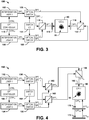
- FIG. 3 illustrates an example of an interrogation system 100.
- the interrogation system 100 can correspond to a first example of the interrogation system 66.
- FIG. 2 illustrates an example of the interrogation system 66.
- the interrogation system 100 includes a first laser 102 that is configured to generate a first optical beam OPT 1 and a second laser 104 that is configured to generate a second optical beam OPT 2 .
- the first optical beam OPT 1 is provided to an optical switch 106
- the second optical beam OPT 2 is provided to an optical switch 108.
- the optical switches 106 and 108 are each configured to switch the respective first and second optical beams OPT 1 and OPT 2 between a first polarizing beam-combiner 110 and a second polarizing beam-combiner 112, respectively, in response to a switching local oscillator ("SWITCH LO") 114.
- SWITCH LO switching local oscillator
- the switching local oscillator 114 can be controlled by the local oscillator 52 to concurrently switch the outputs of each of the optical switches 106 and 108 at a substantially high frequency to provide switching at approximately hundreds to thousands of times during the CPT interrogation stage.
- the interrogation system 100 also includes a CPT controller 115 that is configured to provide a first control signal CTRL 1 to the first laser 102 and a second control signal CTRL 2 to the second laser 104.
- the control signals CTRL 1 and CTRL 2 can be implemented to provide a variable intensity of the respective first and second optical beams OPT 1 and OPT 2 with respect to each other.
- the difference optical beam OPT ⁇ can have an intensity that is a proportion of the varying intensities of the first and second optical beams OPT 1 and OPT 2 during the CPT interrogation stage, as described in greater detail herein.
- the excitation of the population of the alkali metal atoms 58 from the first state to the second state can be provided in a manner that substantially mitigates deleterious AC stark shifts.
- the switching local oscillator 114 can command the optical switch 106 to provide the first optical signal OPT 1 as an output optical signal OPT 1_1 that is provided to the first polarizing beam-combiner 110.
- the switching local oscillator 114 can command the optical switch 108 to provide the second optical signal OPT 2 as an output optical signal OPT 2_1 that is likewise provided to the first polarizing beam-combiner 110.
- the optical beams OPT 1_1 and OPT 2_1 can each be linearly polarized with orthogonal linear polarizations relative to each other.
- the first polarizing beam-combiner 110 can provide the difference optical beam OPT ⁇ as a single beam having the respective orthogonal linearly polarized optical beams OPT 1_1 and OPT 2_1 .
- the difference optical beam OPT ⁇ is provided through a variable wave plate (e.g., a quarter-wave plate) 116 to provide the difference optical beam OPT ⁇ as a single beam having respective opposite circularly-polarized optical beams OPT 1_1 and OPT 2_1 (e.g., at counter-rotating circular polarizations + ⁇ and - ⁇ ).
- the circularly-polarized difference optical beam OPT ⁇ is thus provided through the cell 60 in the first direction during the first sequence.
- the switching local oscillator 114 can command the optical switch 106 to provide the first optical signal OPT 1 as an output optical signal OPT 1_2 that is provided to the second polarizing beam-combiner 112.
- the switching local oscillator 114 can command the optical switch 108 to provide the second optical signal OPT 2 as an output optical signal OPT 2_2 that is likewise provided to the second polarizing beam-combiner 112.
- the optical beams OPT 1_2 and OPT 2_2 can each be linearly polarized with orthogonal linear polarizations relative to each other.
- the second polarizing beam-combiner 112 can provide the difference optical beam OPT ⁇ as a single beam having the respective orthogonal linearly polarized optical beams OPT 1_2 and OPT 2_2 .
- the difference optical beam OPT ⁇ is provided through a variable wave plate (e.g., a quarter-wave plate) 118 to provide the difference optical beam OPT ⁇ as a single beam having respective opposite circularly-polarized optical beams OPT 1_2 and OPT 2_2 (e.g., at counter-rotating circular polarizations + ⁇ and - ⁇ ).
- the circularly-polarized difference optical beam OPT ⁇ is thus provided through the cell 60 in the second direction opposite the first direction during the second sequence.
- the difference optical beam OPT ⁇ can be rapidly and alternately provided through the cell 60 to drive CPT interrogation of the alkali metal atoms 58 in each of the first and second directions (e.g., at circular polarizations + ⁇ and - ⁇ with respect to the optical beams OPT 1 and OPT 2 , respectively, in each of the first and second sequences) during the CPT interrogation stage.
- the optical switches 106 and 108 can be physically positioned in such a manner as to ensure that the phase of the optical signals OPT 1 and OPT 2 , and thus the optical beams OPT 1_1 and OPT 1_2 and the optical beams OPT 2_1 and OPT 2_2 , is approximately equal with respect to an approximate center of the cell 60 corresponding to a CPT interrogation region.
- the CPT interrogation of the alkali metal atoms 58 can be approximately equal with respect to each of the first and second sequence based on the difference optical beam OPT ⁇ having an approximately equal phase in each of the first and second sequences.
- the optical switches 106 and 108 can be physically positioned such that the path length of the optical signals OPT 1 and OPT 2 are approximately equal with respect to the separate respective directions of application of the difference optical beam OPT ⁇ through the cell 60, or have a path length that is different by an integer number of an equivalent microwave wavelength corresponding to the difference frequency of the two optical beams OPT 1 and OPT 2 (e.g., approximately 4.4 cm for 87-rubidium). Accordingly, the phase of the difference optical beam OPT ⁇ can be approximately equal with respect to the CPT interrogation of the alkali metal atoms 58 in each of the first and second sequence.
- FIG. 4 illustrates another example of an interrogation system 150.
- the interrogation system 150 can correspond to a second example of the interrogation system 66.
- FIG. 4 illustrates another example of an interrogation system 150.
- the interrogation system 150 can correspond to a second example of the interrogation system 66.
- FIG. 2 illustrates another example of the interrogation system 66.
- the interrogation system 150 includes a first laser 152 that is configured to generate a first optical beam OPT 1 and a second laser 154 that is configured to generate a second optical beam OPT 2 .
- the first optical beam OPT 1 is provided to an optical switch 156
- the second optical beam OPT 2 is provided to an optical switch 158.
- the optical switches 156 and 158 are each configured to switch the respective first and second optical beams OPT 1 and OPT 2 between a first polarizing beam-combiner 160 and a second polarizing beam-combiner 162, respectively, in response to a switching local oscillator ("SWITCH LO") 164.
- SWITCH LO switching local oscillator
- the switching local oscillator 164 can be controlled by the local oscillator 52 to concurrently switch the outputs of each of the optical switches 156 and 158 at a substantially high frequency to provide switching at approximately hundreds to thousands of times during the CPT interrogation stage.
- the interrogation system 150 also includes a CPT controller 165 that is configured to provide a first control signal CTRL 1 to the first laser 152 and a second control signal CTRL 2 to the second laser 154.
- the control signals CTRL 1 and CTRL 2 can be implemented to provide a variable intensity of the respective first and second optical beams OPT 1 and OPT 2 with respect to each other.
- the difference optical beam OPT ⁇ can have an intensity that is a proportion of the varying intensities of the first and second optical beams OPT 1 and OPT 2 during the CPT interrogation stage, as described in greater detail herein.
- the excitation of the population of the alkali metal atoms 58 from the first state to the second state can be provided in a manner that substantially mitigates deleterious AC stark shifts.
- the switching local oscillator 164 can command the optical switch 156 to provide the first optical signal OPT 1 as an output optical signal OPT 1_1 that is provided to the first polarizing beam-combiner 160.
- the switching local oscillator 164 can command the optical switch 158 to provide the second optical signal OPT 2 as an output optical signal OPT 2_1 that is likewise provided to the second polarizing beam-combiner 162.
- the optical beams OPT 1_1 and OPT 2_1 can each be linearly polarized with orthogonal linear polarizations relative to each other.
- the first polarizing beam-combiner 160 can provide an optical beam OPT A corresponding to the first optical beam OPT 1 (e.g., the optical beam OPT 1_1 ) during the first sequence and the second polarizing beam-combiner 162 can provide an optical beam OPT B corresponding to the second optical beam OPT 2 (e.g., the optical beam OPT 2_1 ) during the first sequence.
- the optical beams OPT A and OPT B thus have orthogonal linear polarizations relative to each other, and are provided to a third polarizing beam-combiner 166 to provide the difference optical beam OPT ⁇ as a single beam having the respective orthogonal linearly polarized optical beams OPT A and OPT B (e.g., the optical beams OPT 1_1 and OPT 2_1 ).
- the difference optical beam OPT ⁇ is provided through a variable wave plate (e.g., a quarter-wave plate) 168 to provide the difference optical beam OPT ⁇ as a single beam having respective opposite circularly-polarized optical beams OPT A and OPT B (e.g., at counter-rotating circular polarizations + ⁇ and - ⁇ with respect to the optical beams OPT 1 and OPT 2 , respectively) during the first sequence.
- a variable wave plate e.g., a quarter-wave plate
- the switching local oscillator 164 can command the optical switch 156 to provide the first optical signal OPT 1 as an output optical signal OPT 1_2 that is provided to the second polarizing beam-combiner 162.
- the switching local oscillator 164 can command the optical switch 158 to provide the second optical signal OPT 2 as an output optical signal OPT 2_2 that is likewise provided to the first polarizing beam-combiner 160.
- the optical beams OPT 1_2 and OPT 2_2 can each be linearly polarized with orthogonal linear polarizations relative to each other.
- the first polarizing beam-combiner 160 can provide the optical beam OPT A corresponding to the second optical beam OPT 2 (e.g., the optical beam OPT 2_2 ) during the second sequence and the second polarizing beam-combiner 162 can provide the optical beam OPT B corresponding to the first optical beam OPT 1 (e.g., the optical beam OPT 1_2 ) during the second sequence.
- the optical beams OPT A and OPT B thus have orthogonal linear polarizations relative to each other, and are provided to the third polarizing beam-combiner 166 to provide the difference optical beam OPT ⁇ as the single beam having the respective orthogonal linearly polarized optical beams OPT A and OPT B (e.g., the optical beams OPT 1_2 and OPT 2_2 ).
- the difference optical beam OPT ⁇ is provided through the variable wave plate 168 to provide the difference optical beam OPT ⁇ as a single beam having respective opposite circularly-polarized optical beams OPT A and OPT B (e.g., at counter-rotating circular polarizations - ⁇ and + ⁇ with respect to the optical beams OPT 1 and OPT 2 , respectively) during the second sequence. Therefore, the circular polarizations of the respective first and second optical beams OPT 1 and OPT 2 are reversed in the second sequence relative to the first sequence.
- the difference optical beam OPT ⁇ is provided through the cell 60 from the variable wave plate 168.
- the difference optical beam OPT ⁇ passes through the cell 60 and exits as a difference optical beam OPT ⁇ 1 through a variable wave plate (e.g., a quarter-wave plate) 170 to provide a difference optical beam OPT ⁇ 2 .
- the difference optical beam OPT ⁇ 2 is thus converted to a single beam that includes the respective orthogonally-linearly polarized first and second optical beams OPT A and OPT B in response to the variable wave plate 170.
- the difference optical beam OPT ⁇ 2 is reflected by a mirror 172 and is provided to the variable wave plate 170 that converts the orthogonally-linearly polarized optical beams OPT A and OPT B of the difference optical beam OPT ⁇ 2 back to respective opposite circular polarizations to provide a difference optical beam OPT ⁇ 3 .
- the circular polarizations of the difference optical beam OPT ⁇ 3 are reversed relative to the circular polarizations of the difference optical beam OPT ⁇ 1 .
- the difference optical beam OPT ⁇ in the first sequence, can have circular polarizations + ⁇ and - ⁇ with respect to the optical beams OPT 1 and OPT 2 , respectively.
- the difference optical beam OPT ⁇ 3 can have the opposite relative circular polarizations - ⁇ and + ⁇ with respect to the optical beams OPT 1 and OPT 2 , respectively, during the first sequence.
- the difference optical beam OPT ⁇ in the second sequence, can have circular polarizations - ⁇ and + ⁇ with respect to the optical beams OPT 1 and OPT 2 , respectively.
- the difference optical beam OPT ⁇ 3 can have the opposite relative circular polarizations + ⁇ and - ⁇ with respect to the optical beams OPT 1 and OPT 2 , respectively, during the second sequence.
- the alkali metal atoms 58 can be sensitive only to a given circular polarization orientation of the difference optical beam OPT ⁇ (e.g., at circular polarizations + ⁇ and - ⁇ with respect to the optical beams OPT 1 and OPT 2 , respectively) and insensitive to an opposite circular polarization direction (e.g., at circular polarizations - ⁇ and + ⁇ with respect to the optical beams OPT 1 and OPT 2 , respectively). Therefore, during the first sequence, the optical difference beam OPT ⁇ can be provided from the variable wave plate 168 through the cell 60 in the first direction as having circular polarizations + ⁇ and - ⁇ with respect to the optical beams OPT 1 and OPT 2 , respectively.
- the optical difference beam OPT A3 can be provided from the variable wave plate 170 through the cell 60 in the second direction as having circular polarizations - ⁇ and + ⁇ with respect to the optical beams OPT 1 and OPT 2 , respectively. Therefore, the alkali metal atoms 58 can be excited in response to the optical difference beam OPT ⁇ provided in the first direction and insensitive to the optical difference beam OPT ⁇ 3 provided in the second direction opposite the first direction during the first sequence.
- the optical difference beam OPT ⁇ can be provided from the variable wave plate 168 through the cell 60 in the first direction as having circular polarizations - ⁇ and + ⁇ with respect to the optical beams OPT 1 and OPT 2 , respectively.
- the optical difference beam OPT ⁇ 3 can be provided from the variable wave plate 170 through the cell 60 in the second direction as having circular polarizations + ⁇ and - ⁇ with respect to the optical beams OPT 1 and OPT 2 , respectively. Therefore, the alkali metal atoms 58 can be excited in response to the optical difference beam OPT ⁇ 3 provided in the second direction and insensitive to the optical difference beam OPT ⁇ provided in the first direction opposite the second direction during the second sequence.
- the difference optical beam OPT ⁇ can be rapidly and alternately provided through the cell 60 to drive CPT interrogation of the alkali metal atoms 58 in each of the first and second directions at circular polarizations + ⁇ and - ⁇ with respect to the optical beams OPT 1 and OPT 2 , respectively, in each of the first and second sequences, during the CPT interrogation stage.
- the mirror 172 can be physically positioned in such a manner as to ensure that the phase of the optical signals OPT 1 and OPT 2 , and thus the phase of the difference optical beam OPT ⁇ , is approximately equal with respect to an approximate center of the cell 60 corresponding to a CPT interrogation region.
- the CPT interrogation of the alkali metal atoms 58 can be approximately equal with respect to each of the first and second sequence based on the difference optical beam OPT ⁇ having an approximately equal phase in each of the first and second sequences.
- the mirror 172 can be physically positioned such that a distance from the approximate center of the cell 60 corresponding to a CPT interrogation region is approximately equal to one-half of an integer number of an equivalent microwave wavelength corresponding to the difference frequency of the two optical beams OPT 1 and OPT 2 (e.g., approximately 4.4 cm for 87-rubidium). Accordingly, the phase of the difference optical beam OPT ⁇ can be approximately equal with respect to the CPT interrogation of the alkali metal atoms 58 in each of the first and second sequence.
- the optical response OPT DET is provided to a fluorescence detector 78 of the oscillator system 54.
- the fluorescence detector 78 is configured to monitor an intensity of the optical response OPT DET in each of the trapping stage and the CPT interrogation stage of the given clock measurement cycle.
- the fluorescence detector 78 can monitor the baseline optical response OPT DET of the alkali metal atoms 58 in response to the excitation of the alkali metal atoms 58 by the trapping magnetic field and the optical trapping beam OPT T during the trapping stage, and can monitor the optical response OPT DET of the alkali metal atoms 58 in response to the excitation of a population of the alkali metal atoms 58 by the difference optical beam OPT ⁇ during the CPT interrogation stage.
- the fluorescence detector 78 is configured to generate an intensity signal INTS in response to the optical response OPT DET , such that the intensity signal INTS can have an amplitude that corresponds to the intensity of the optical response OPT DET .
- the intensity signal INTS is provided to a control system 80 that can be configured as a processor or application specific integrated circuit (ASIC).
- the control system 80 can be configured to compare the intensity signal INTS in each of the trapping stage and the CPT interrogation stage. Therefore, the control system 80 can compare the optical response OPT DET of the excited alkali metal atoms 58 during the CPT interrogation stage relative to the baseline optical response OPT DET provided during the trapping stage. As an example, the control system 80 can perform the comparison at the conclusion of each clock measurement cycle and can thus determine a frequency shift in the frequency of the local oscillator 52 over the course of multiple clock measurement cycles.
- ASIC application specific integrated circuit
- the oscillator system 54 also includes a frequency stabilization system 82 that is configured to provide a frequency stabilization signal BT STBL to each of the first and second interrogation lasers 68 and 70 to set and stabilize the difference frequency between the first and second optical beams OPT 1 and OPT 2 .
- the frequency stabilization system 82 is configured to stabilize the difference frequency between the first and second optical beams OPT 1 and OPT 2 in response to a stable frequency reference F STBL provided from the local oscillator 52.
- the frequency stabilization system 82 can include a master laser (not shown) that is stabilized by the stable frequency reference F STBL , and the frequency stabilization system 82 can stabilize the difference frequency between the first laser 68 and the second laser 70 based on a beat stabilization system that compares a frequency of the first and second optical beams OPT 1 and OPT 2 , respectively, with the frequency of the master laser.
- the frequency stabilization signal BT STBL can correspond to a beat stabilization feedback to provide stabilization of the first and second lasers 68 and 70, and thus the first and second optical beams OPT 1 and OPT 2 , respectively.
- the frequency stabilization system 82 can be configured to adjust the amplitude of the difference frequency based on the frequency stabilization signal BT STBL .
- the frequency stabilization system 82 can be configured to adjust the frequency of one of the first and second optical beams OPT 1 and OPT 2 while maintaining the frequency of the other of the first and second optical beams OPT 1 and OPT 2 . Therefore, in each of the clock measurement cycles, the difference frequency of the difference optical beam OPT ⁇ can be off-resonance from a resonant frequency corresponding to maximum excitation of the alkali metal atoms 58 from the first state (e.g., ⁇ 1,-1>) to the second state (e.g., ⁇ 2,1>).
- the off-resonance frequency can be switched substantially equally and oppositely from the resonant frequency from one clock measurement cycle to the next, such as in alternating clock measurement cycles, or can be switched in a pseudo-random sequence of the respective clock measurement cycles.
- the difference between the optical response OPT DET of the off-resonance frequency excitation of the alkali metal atoms 58 in each of a first off-resonance frequency + ⁇ and a second off-resonance frequency - ⁇ with respect to the resonant frequency can be determinative of an error of the resonant frequency, such as resulting from a drift of the stable frequency reference of the local oscillator 52.
- FIG. 5 illustrates an example of a graph 200 of alkali metal excitation.
- the graph 200 demonstrates an off-resonance frequency on the X-axis, in Hz, relative to a predetermined resonant frequency corresponding to an expected substantial maximum excitation of the alkali metal atoms 58 from the first state to the second state.
- the predetermined resonant frequency corresponds to a frequency setting of the frequency stabilization system 82 with respect to the difference optical beam OPT ⁇ .
- the alkali metal atoms 58 can correspond to 87-rubidium atoms, and the maximum excitation of the 87-rubidium atoms 58 is demonstrated as an inverted peak 202 that is centered at an off-resonance frequency of zero.
- the proportion (e.g., percentage) of the 87-rubidium atoms 58 that are not excited can thus affect the optical response OPT DET during the CPT interrogation stage, such that lower proportions of the 87-rubidium atoms 58 that are not excited results in a greater intensity of the optical response OPT DET .
- the proportion (e.g., percentage) of the 87-rubidium atoms 58 that are not excited can thus affect the optical response OPT DET during the CPT interrogation stage, such that lower proportions of the 87-rubidium atoms 58 that are not excited results in a greater intensity of the optical response OPT DET .
- the graph 200 thus demonstrates that the excitation of the alkali metal atoms 58 (e.g., 87-rubidium atoms) has a very narrow linewidth.
- the graph 200 also demonstrates a first off-resonant frequency 204 and a second off-resonant frequency 206, demonstrated as respective dotted lines.
- the alkali metal atoms 58 e.g., 87-rubidium atoms
- the first off-resonant frequency 204 is demonstrated as a + ⁇ off-resonant frequency (e.g., plus approximately 20 Hz relative to the resonant frequency at the off-resonance of 0 Hz)
- the second off-resonant frequency 206 is demonstrated as a - ⁇ off-resonant frequency (e.g., minus approximately 20 Hz relative to the resonant frequency at the off-resonance of 0 Hz).
- the graph At the resonant frequency at the off-resonance of 0 Hz, the graph demonstrates that approximately 25% of the alkali metal atoms 58 are not excited to the second state during the CPT interrogation stage.
- the percentage of the alkali metal atoms 58 that are not excited increases in a sharply linear manner, achieving an approximately flat (e.g., asymptotic) characteristic at approximately 30 Hz and -30 Hz, respectively.
- the first off-resonant frequency 204 and a second off-resonant frequency 206 are each equal and opposite the inverted peak 202, and thus correspond to approximately 50% of the alkali metal atoms 58 are not excited to the second state during the CPT interrogation stage.
- the frequency stabilization system 82 can be configured to set the difference frequency of the difference optical beam OPT ⁇ to one of the first off-resonant frequency 204 and the second off-resonant frequency 206 during the CPT interrogation stage of each of the clock measurement cycles.
- the frequency stabilization system 82 can adjust the frequency of one of the first and second optical beams OPT 1 and OPT 2 while maintaining the frequency of the other of the first and second optical beams OPT 1 and OPT 2 . Therefore, in each of the clock measurement cycles, the difference frequency of the difference optical beam OPT ⁇ can be off-resonance from the resonant frequency inverted peak 202 by + ⁇ or - ⁇ in each of the clock measurement cycles.
- the optical response OPT DET can be significantly different between the difference optical beam OPT ⁇ being provided at the first off-resonance frequency 204 relative to the second off-resonance frequency 206, as demonstrated in the example of FIG. 6 .
- FIG. 6 illustrates another example of a graph 250 of the alkali metal excitation.
- the graph 250 corresponds to the graph 200 in the example of FIG. 5 .
- the predetermined resonant frequency setting of the frequency stabilization system 82 is demonstrated as having drifted by a frequency amplitude of +f. Therefore, the actual resonant frequency corresponding to the actual substantial maximum excitation of the alkali metal atoms 58 from the first state to the second state is shifted by approximately 5 Hz.
- the first and second off-resonant frequencies 204 and 206 provide significantly different excitation of the population (e.g., proportion) of the 87-rubidium atoms 58. Particularly, in the example of FIG.
- the first off-resonance frequency + ⁇ provides an approximate 32% of the 87-rubidium atoms not being excited to the second state
- the second off-resonance frequency - ⁇ provides an approximate 70% of the 87-rubidium atoms not being excited to the second state. Therefore, a given clock measurement cycle in which the difference optical frequency of the difference optical beam OPT ⁇ is provided at the first off-resonance frequency + ⁇ provides a significantly different optical response OPT DET relative to the optical response of another clock measurement cycle in which the difference optical beam OPT ⁇ is provided at the difference frequency of the off-resonance frequency - ⁇ . Accordingly, the fluorescence detector 78 can measure the difference in intensity of each of the optical responses of the respective clock measurement cycles.
- the control system 80 in response to measuring the optical response OPT DET of a first clock measurement cycle corresponding to a difference frequency of the first off-resonance frequency + ⁇ and to measuring the optical response OPT DET of a second clock measurement cycle corresponding to a difference frequency of the second off-resonance frequency - ⁇ , the control system 80 is configured to compare a difference in intensity of the optical responses OPT DET (e.g., based on the respective intensity signals INTS). In response to detecting a difference in the intensity of the optical responses OPT DET in each of the respective clock measurement cycles, the control system 80 can detect a drift in the actual resonant frequency of the alkali metal atoms 58.
- the control system 80 can provide a frequency feedback signal F FDBK to the local oscillator 52.
- the local oscillator 52 can adjust the respective stable frequency reference F STBL .
- the frequency stabilization system 82 is configured to stabilize the difference frequency between the first and second lasers 68 and 70, and thus the respective first and second optical beams OPT 1 and OPT 2 , based on the stable frequency reference F STBL , the difference frequency of the difference optical beam OPT ⁇ can thus be adjusted in a feedback manner. Accordingly, the interrogation of the alkali metal atoms 58 over a sequence of clock measurement cycles can provide for a very accurate stabilization of the stable frequency reference F STBL that is output from the local oscillator 52.
- FIG. 7 illustrates an example of a timing diagram 300.
- the timing diagram 300 corresponds to the timing of each clock measurement cycle with respect to the signals and timing that define the given clock measurement cycle. Reference is to be made to the examples of FIGS. 1-6 in the following description of the example of FIG. 7 .
- the timing diagram 300 demonstrates the separate stages of each of the clock measurement cycles. It is to be understood that the stages are not demonstrated as scaled with respect to each other.
- the clock measurement cycle begins with the trapping stage 302.
- the optical trapping beam OPT T is provided through the cell 60, as well as the trapping magnetic field B TRAP provided from the trapping magnetic field generator 64.
- the alkali metal atoms 58 may receive additional stimulus to ensure excitation of the substantially the entirety of the alkali metal atom population. Therefore, in the example of FIG.
- the trapping stage 302 can have a duration of approximately 50 milliseconds.
- the atomic clock system 50 can obtain a source of the cold alkali atoms and a baseline optical response OPT DET of the alkali metal atoms 58.
- the clock measurement cycle transitions to an optical molasses stage 304.
- the optical trapping beam OPT T is maintained through the cell 60, as well as the first optical beam OPT 1 , but the trapping magnetic field B TRAP is deactivated.
- the optical trapping beam OPT T can provide further cooling of the alkali metal atoms 58.
- the alkali metal atoms 58 can reduce in temperature to near absolute zero (e.g., approximately 5 ⁇ K), such that the alkali metal atoms 58 can greatly reduce in diffusion velocity (e.g., a few centimeters per second).
- the alkali metal atoms 58 can be substantially contained in preparation for interrogation.
- the optical molasses stage 304 can have a duration of approximately 25 ms.
- the clock measurement cycle transitions to an atom state preparation stage 306.
- the optical trapping beam OPT T is deactivated, and the second optical beam OPT 2 while the first optical beam OPT 1 is maintained.
- the uniform clock magnetic field B TRAN is activated at the time T 2 .
- the atom state preparation stage 306 sets the conditions to begin an interrogation during the given clock measurement cycle.
- the atom state preparation stage 306 can have a duration of approximately 2 ms.
- a CPT interrogation stage 308 begins.
- the CPT interrogation stage 308 corresponds to the CPT interrogation stage during which the difference optical beam is alternately and rapidly provided through the cell 60 in the first and second directions, as described in greater detail herein.
- the first and second optical beams OPT 1 and OPT 2 are demonstrated as being provided at a variable intensity with respect to each other.
- the second optical beam OPT 2 begins to increase adiabatically in intensity until reaching an amplitude peak at a time T 4 .
- the second optical beam OPT 2 begins to decrease adiabatically, and concurrently beginning at the time T 4 , the first optical beam OPT 1 begins to increase adiabatically.
- the first optical beam OPT 1 reaches a peak, and the second optical beam OPT 2 decreases in intensity to approximately zero.
- the first optical beam OPT 1 decreases in intensity, and decreases in intensity to approximately zero at a time T 6 .
- the CPT interrogation stage 308 can have a duration of approximately 20 ms.
- the excitation of the population of the alkali metal atoms 58 from the first state to the second state can be provided in a manner that substantially mitigates deleterious AC stark shifts.
- the clock measurement cycle transitions to a state readout stage 310.
- the optical trapping beam OPT T is reactivated, and the uniform clock magnetic field B TRAN is deactivated.
- the state readout stage 310 the population of the alkali metal atoms 58 have transitioned from the first state (e.g., the state ⁇ 1,-1>) to the second state (e.g., the state ⁇ 2,1>), such that the population of the alkali metal atoms 58 provide an optical response OPT DET during the state readout stage 310.
- the oscillator system 54 can control the frequency of the local oscillator 52 based on the optical response OPT DET (e.g., based on the optical response OPT DET over a sequence of clock measurement cycles), as described herein.
- the state readout stage 310 can have a duration of approximately 3 ms.
- FIG. 8 a methodology in accordance with various aspects of the present invention will be better appreciated with reference to FIG. 8 . While, for purposes of simplicity of explanation, the methodology of FIG. 8 is shown and described as executing serially, it is to be understood and appreciated that the present invention is not limited by the illustrated order, as some aspects could, in accordance with the present invention, occur in different orders and/or concurrently with other aspects from that shown and described herein. Moreover, not all illustrated features may be required to implement a methodology in accordance with an aspect of the present invention.
- FIG. 8 illustrates an example of a method 350 for stabilizing a local oscillator (e.g., the local oscillator 12) of an atomic clock system (e.g., the atomic clock system 10).
- alkali metal atoms e.g., the alkali metal atoms 18
- CPT sequential coherent population trapping
- an optical difference beam (e.g., the difference optical beam OPT ⁇ ) comprising a first optical beam (e.g., the first optical beam OPT 1 ) having a first frequency and a second optical beam (e.g., the second optical beam OPT 2 ) having a second frequency different from the first frequency is generated.
- a direction of the optical difference beam is periodically alternated through the cell during a CPT interrogation stage (e.g., the CPT interrogation stage 308) of each of the sequential clock measurement cycles to drive CPT interrogation of the trapped alkali metal atoms based on alternating relative circular polarizations of the first and second optical beams.
- an optical response (e.g., the optical response OPT DET ) of the CPT interrogated alkali metal atoms is monitored during a state readout stage (e.g., the state readout stage 310) in each of the sequential clock measurement cycles.
- a frequency of the local oscillator is adjusted based on the optical response of the CPT interrogated alkali metal atoms of each of the sequential clock measurement cycles relative to the baseline optical response.
Landscapes
- Physics & Mathematics (AREA)
- Spectroscopy & Molecular Physics (AREA)
- Life Sciences & Earth Sciences (AREA)
- Ecology (AREA)
- General Physics & Mathematics (AREA)
- Engineering & Computer Science (AREA)
- Plasma & Fusion (AREA)
- Stabilization Of Oscillater, Synchronisation, Frequency Synthesizers (AREA)
- Investigating Or Analysing Materials By Optical Means (AREA)
Claims (15)
- Atomuhrsystem (10, 50), umfassend:ein optisches Fangsystem (16), das Alkalimetallatome (18, 58) in einer Zelle (60) während einer Fangphase von jedem von sequentiellen kohärenten Populationsfangzyklen (CPT / Coherent Population Trapping) einfängt,ein Abfragesystem (20, 66, 100), das einen optischen Differenzstrahl erzeugt, um die CPT-Abfrage der Alkalimetallatome anzutreiben, wobei der optische Differenzstrahl einen ersten optischen Strahl mit einer ersten Frequenz und einen zweiten optischen Strahl mit einer zweiten Frequenz umfasst, die sich von der ersten Frequenz unterscheidet, dadurch gekennzeichnet,
dass das Atomuhrsystem ein Oszillatorsystem (14) umfasst, das eine Frequenz eines lokalen Oszillators (12, 52) basierend auf einer optischen Antwort der CPT-abgefragten Alkalimetallatome als Reaktion auf den optischen Differenzstrahl während einer Zustandsauslesephase einstellt. - System nach Anspruch 1, wobei das Abfragesystem eine Richtungssteuerung (22, 76) umfasst, die periodisch eine Richtung des optischen Differenzstrahls durch die Zelle während einer CPT-Abfragephase jedes der sequentiellen Taktmesszyklen wechselt.
- System nach Anspruch 2, wobei das Oszillatorsystem die Frequenz des lokalen Oszillators basierend auf der optischen Antwort der CPT-abgefragten Alkalimetallatome als Reaktion auf den optischen Differenzstrahl während der Zustandsauslesephase in jeder der sequentiellen Taktmesszyklen einstellt.
- System nach Anspruch 2 oder 3, wobei die Richtungssteuerung umfasst:einen ersten Strahlkombinierer, der konfiguriert ist, den ersten und den zweiten optischen Strahl zu empfangen, um den optischen Differenzstrahl in einer ersten Richtung durch die Zelle in einer ersten Sequenz bereitzustellen,einen zweiten Strahlkombinierer, der konfiguriert ist, den ersten und den zweiten optischen Strahl zu empfangen, um den optischen Differenzstrahl in einer zweiten Richtung durch die Zelle entgegen der ersten Richtung in einer zweiten Sequenz bereitzustellen undoptische Schalter, die konfiguriert sind, zwischen der ersten und der zweiten Sequenz zu wechseln.
- System nach Anspruch 4, wobei der erste Strahlkombinierer konfiguriert ist, den ersten und den zweiten optischen Strahl zu kombinieren, um den optischen Differenzstrahl durch eine erste variable Wellenplatte und durch die Zelle in der ersten Richtung bei einer ersten relativen zirkularen Polarisation in der ersten Sequenz bereitzustellen, und wobei der zweite Strahlkombinierer konfiguriert ist, den ersten und den zweiten optischen Strahl zu kombinieren, um den optischen Differenzstrahl durch eine zweite variable Wellenplatte und durch die Zelle in der zweiten Richtung bei einer zweiten relativen zirkularen Polarisation in der zweiten Sequenz bereitzustellen.
- System nach Anspruch 5, wobei eine Weglänge des ersten und des zweiten optischen Signals in Bezug auf die jeweiligen getrennten ersten und zweiten Richtungen des optischen Differenzstrahls durch die Zelle ungefähr gleich ist oder die Weglänge des ersten und des zweiten optischen Signals sich durch eine ganzzahlige Zahl einer äquivalenten Mikrowellenwellenlänge unterscheidet, die der Differenzfrequenz des ersten und zweiten optischen Strahls entspricht.
- System nach den Ansprüchen 4 bis 6, wobei der erste Strahlkombinierer den ersten und den zweiten optischen Strahl empfängt, um einen des ersten optischen Strahls und des zweiten optischen Strahls bei einer ersten linearen Polarisation in der ersten Sequenz beziehungsweise der zweiten Sequenz bereitzustellen, wobei der zweite Strahlkombinierer den ersten und den zweiten optischen Strahl empfängt, um einen des zweiten optischen Strahls und des ersten optischen Strahls bei einer zweiten linearen Polarisation in der ersten Sequenz bzw. der zweiten Sequenz bereitzustellen, wobei das System ferner umfasst:einen dritten Strahlkombinierer, der konfiguriert ist, den ersten und den zweiten optischen Strahl zu kombinieren, um den optischen Differenzstrahl durch eine erste variable Wellenplatte in jeder der ersten und zweiten Sequenzen bereitzustellen, um den optischen Differenzstrahl in jeder einer ersten relativen zirkularen Polarisation bzw. einer zweiten relativen zirkularen Polarisation in einer ersten Richtung durch die Zelle in der ersten Sequenz bzw. der zweiten Sequenz bereitzustellen, undein Reflexionssystem, umfassend einen Spiegel und eine zweite variable Wellenplatte, konfiguriert, den optischen Differenzstrahl in der zweiten Richtung durch die Zelle in jeder der ersten und zweiten Sequenzen zu reflektieren, um den optischen Differenzstrahl in jeder der zweiten relativen zirkularen Polarisation bzw. der ersten relativen zirkularen Polarisation in der ersten Sequenz bzw. der zweiten Sequenz bereitzustellen, wobei der Spiegel physikalisch so positioniert ist, dass ein Abstand vom ungefähren Zentrum der Zelle entsprechend einem CPT-Abfragebereich der Alkalimetallatome ungefähr gleich einer Hälfte einer Ganzzahl einer äquivalenten Mikrowellenwellenlänge entsprechend der Differenzfrequenz des ersten und zweiten optischen Strahls ist.
- System nach einem der vorhergehenden Ansprüche, wobei das optische Fangsystem als ein magneto-optisches Fangsystem (MOT) konfiguriert ist, umfasst:einen ersten Magnetfeldgenerator, der konfiguriert ist, ein Fangmagnetfeld zu erzeugen, das konfiguriert ist, die Alkalimetallatome in der Zelle als Reaktion auf einen optischen Fangstrahl einzufangen, undeinen zweiten Magnetfeldgenerator, der konfiguriert ist, ein gleichmäßiges Taktmagnetfeld während der CPT-Abfragephase der sequentiellen Taktmesszyklen zu erzeugen, wobei das gleichmäßige Taktmagnetfeld eine Amplitude aufweist, die auf Zeeman-Verschiebungseigenschaften der Alkalimetallatome basiert, um die CPT-Abfrage einer Population der Alkalimetallatome von einem ersten Energiezustand in einen zweiten Energiezustand anzutreiben.
- System nach einem der vorhergehenden Ansprüche, wobei das Abfragesystem konfiguriert ist, eine Intensität von jedem des ersten optischen Strahls und des zweiten optischen Strahls während der CPT-Abfragephase zu steuern, um einen variablen relativen Intensitätsanteil bereitzustellen, um eine AC-Stark-Verschiebung im Zusammenhang mit der Anregung der Alkalimetallatome zu mildern.
- System nach einem der vorhergehenden Ansprüche, wobei eine Frequenz des ersten optischen Strahls und eine Frequenz des zweiten optischen Strahls eingestellt sind, den optischen Differenzstrahl bei einer Differenzfrequenz bereitzustellen, die gegenüber einer In-Resonanz-Frequenz verstimmt ist, die einem Höchstwert zugeordnet ist, der einer maximalen Anregung einer Population der Alkalimetallatome von einem ersten Energiezustand zu einem zweiten Energiezustand entspricht.
- System nach Anspruch 10, wobei die Differenzfrequenz in jedem der sequentiellen Taktmesszyklen so eingestellt ist, dass sie eine von +Δ und -Δ der In-Resonanz-Frequenz in jedem von sequentiellen Taktmesszyklen ist, um eine Differenzintensität zu bestimmen, die der optischen Antwort des CPT-abgefragten Alkalimetallatome während der Zustandsauslesephase in den sequentiellen Taktmesszyklen zugeordnet ist.
- Verfahren zum Stabilisieren eines lokalen Oszillators (12, 52) eines Atomuhrsystems (10, 50), wobei das Verfahren umfasst:Fangen von Alkalimetallatomen (18, 58) in einer Zelle (60) während einer Fangphase von jedem von sequentiellen kohärenten Populationsfangzyklen (CPT / Coherent Population Trapping), um eine Quelle für kalte Alkaliatome und eine optische Grundantwort der Alkalimetallatome bereitzustellen,Erzeugen eines optischen Differenzstrahls, umfassend einen ersten optischen Strahl mit einer ersten Frequenz und einen zweiten optischen Strahl mit einer zweiten Frequenz, die sich von der ersten Frequenz unterscheidet,Bereitstellen des optischen Differenzstrahls durch die Zelle während einer CPT-Abfragephase jedes der sequentiellen Taktmesszyklen, um die CPT-Abfrage der eingefangenen Alkalimetallatome anzutreiben,Überwachen einer optischen Antwort der CPT-abgefragten Alkalimetallatome während einer Zustandsauslesephase in jedem der sequentiellen Taktmesszyklen,Einstellen einer Frequenz des lokalen Oszillators basierend auf der optischen Antwort der CPT-abgefragten Alkalimetallatome jedes der sequentiellen Taktmesszyklen relativ zur optischen Basisantwort.
- Verfahren nach Anspruch 12, wobei das Bereitstellen des optischen Differenzstrahls das periodische Wechseln einer Richtung des optischen Differenzstrahls durch die Zelle während der CPT-Abfragephase jedes der sequentiellen Taktmesszyklen umfasst, um die CPT-Abfrage der eingefangenen Alkalimetallatome basierend auf relativen zirkularen Polarisationen des ersten und zweiten optischen Strahls zu steuern.
- Verfahren nach Anspruch 13, wobei das periodische Wechseln der Richtung des optischen Differenzstrahls umfasst:Bereitstellen des ersten und zweiten optischen Strahls für einen ersten Strahlkombinierer, um den optischen Differenzstrahl durch eine erste variable Wellenplatte als erste relative zirkulare Polarisation durch die Zelle in einer ersten Richtung in einer ersten Sequenz bereitzustellen,Bereitstellen des ersten und zweiten optischen Strahls für einen zweiten Strahlkombinierer, um den optischen Differenzstrahl durch eine zweite variable Wellenplatte als zweite relative zirkulare Polarisation in einer zweiten Richtung entgegengesetzt zur ersten Richtung durch die Zelle in einer zweiten Sequenz bereitzustellen undAbwechseln zwischen der ersten und der zweiten Sequenz.
- Verfahren nach den Ansprüchen 12 bis 14, wobei das Erzeugen des optischen Differenzstrahls das Bereitstellen des optischen Differenzstrahls bei einer Differenzfrequenz umfasst, die gegenüber einer In-Resonanz-Frequenz verstimmt ist, die einem Höchstwert zugeordnet ist, der einer maximalen Anregung einer Population von der Alkalimetallatome von einem ersten Energiezustand in einen zweiten Energiezustand entspricht, wobei das Verfahren ferner das Einstellen der Differenzfrequenz auf einen von +Δ und -Δ der In-Resonanz-Frequenz in jedem der sequentiellen Taktmesszyklen umfasst, um eine Differenzintensität zu bestimmen, die der optischen Antwort der CPT-abgefragten Alkalimetallatome relativ zur Grundlinienintensität während der Zustandsauslesephase in den sequentiellen Taktmesszyklen zugeordnet ist.
Applications Claiming Priority (3)
| Application Number | Priority Date | Filing Date | Title |
|---|---|---|---|
| US201662406653P | 2016-10-11 | 2016-10-11 | |
| US15/722,595 US10539929B2 (en) | 2016-10-11 | 2017-10-02 | Atomic clock system |
| EP17195497.7A EP3309629B1 (de) | 2016-10-11 | 2017-10-09 | Atomuhrsystem |
Related Parent Applications (2)
| Application Number | Title | Priority Date | Filing Date |
|---|---|---|---|
| EP17195497.7A Division EP3309629B1 (de) | 2016-10-11 | 2017-10-09 | Atomuhrsystem |
| EP17195497.7A Division-Into EP3309629B1 (de) | 2016-10-11 | 2017-10-09 | Atomuhrsystem |
Publications (2)
| Publication Number | Publication Date |
|---|---|
| EP3499322A1 EP3499322A1 (de) | 2019-06-19 |
| EP3499322B1 true EP3499322B1 (de) | 2020-08-26 |
Family
ID=60043104
Family Applications (2)
| Application Number | Title | Priority Date | Filing Date |
|---|---|---|---|
| EP17195497.7A Active EP3309629B1 (de) | 2016-10-11 | 2017-10-09 | Atomuhrsystem |
| EP18206585.4A Active EP3499322B1 (de) | 2016-10-11 | 2017-10-09 | Atomuhrsystem |
Family Applications Before (1)
| Application Number | Title | Priority Date | Filing Date |
|---|---|---|---|
| EP17195497.7A Active EP3309629B1 (de) | 2016-10-11 | 2017-10-09 | Atomuhrsystem |
Country Status (4)
| Country | Link |
|---|---|
| US (2) | US10539929B2 (de) |
| EP (2) | EP3309629B1 (de) |
| JP (2) | JP6495409B2 (de) |
| AU (2) | AU2017239529B2 (de) |
Families Citing this family (13)
| Publication number | Priority date | Publication date | Assignee | Title |
|---|---|---|---|---|
| US10539929B2 (en) * | 2016-10-11 | 2020-01-21 | Northrop Grumman Systems Corporation | Atomic clock system |
| US10782368B2 (en) | 2017-05-31 | 2020-09-22 | Northrop Grumman Systems Corporation | Pulsed-beam atomic magnetometer system |
| US11800629B2 (en) * | 2019-02-26 | 2023-10-24 | Nippon Telegraph And Telephone Corporation | Magneto-optical trap method and apparatus using positive and negative g-factors |
| US11133117B2 (en) | 2019-05-08 | 2021-09-28 | Northrop Grumman Systems Corporation | Atomic interferometer system |
| CN110333651B (zh) * | 2019-07-15 | 2021-04-02 | 温州激光与光电子协同创新中心 | 基于相干布居数囚禁模式锁定的激光原子钟 |
| CN111123311B (zh) * | 2019-11-18 | 2021-12-03 | 北京卫星导航中心 | 星载原子钟调频调相方法 |
| WO2021097718A1 (zh) * | 2019-11-20 | 2021-05-27 | 华为技术有限公司 | 一种为自动驾驶提供时间源的方法及装置 |
| CN112304442B (zh) * | 2020-10-28 | 2022-09-02 | 中国科学院国家授时中心 | 双调制cpt差分探测方法及系统 |
| EP4300727A4 (de) * | 2021-02-25 | 2025-07-02 | Univ Tokyo | Atomelektronen-zustandsteiler, atominterferometer, atomübergangsfrequenzmessvorrichtung, atomoszillator, quantencomputer und verfahren zur erzeugung von superpositionszuständen von atomzuständen |
| JP7739823B2 (ja) * | 2021-08-02 | 2025-09-17 | 日本電気株式会社 | 量子干渉装置、原子発振器及び制御方法 |
| WO2023204992A1 (en) * | 2022-04-18 | 2023-10-26 | Northrop Grumman Systems Corporation | Atomic optical reference system |
| JP2023176300A (ja) * | 2022-05-31 | 2023-12-13 | 日本電気株式会社 | 原子発振器 |
| CN119310822B (zh) * | 2024-12-16 | 2025-03-14 | 深圳大学 | 一种相干布居数囚禁冷原子钟装置及其控制方法 |
Citations (1)
| Publication number | Priority date | Publication date | Assignee | Title |
|---|---|---|---|---|
| US20140028405A1 (en) * | 2012-07-27 | 2014-01-30 | Qualcomm Incorporated | Low power microfabricated atomic clock |
Family Cites Families (15)
| Publication number | Priority date | Publication date | Assignee | Title |
|---|---|---|---|---|
| US5136261A (en) | 1990-12-11 | 1992-08-04 | Ball Corporation | Saturated absorption double resonance system and apparatus |
| US7102451B2 (en) * | 2004-02-18 | 2006-09-05 | Princeton University, Office Of Technology, Licensing & Intellectual Property | Method and system for operating an atomic clock with alternating-polarization light |
| JP2009129955A (ja) | 2007-11-20 | 2009-06-11 | Epson Toyocom Corp | 光学系及び原子発振器 |
| EP2131500A3 (de) | 2008-06-02 | 2012-03-07 | SEPA - Sistemi Elettronici Per Automazione S.P.A. | Atomstrahlröhre mit gegenläufigen Licht- oder Atomstrahlen |
| US7893780B2 (en) | 2008-06-17 | 2011-02-22 | Northrop Grumman Guidance And Electronic Company, Inc. | Reversible alkali beam cell |
| JP5369803B2 (ja) * | 2009-03-23 | 2013-12-18 | セイコーエプソン株式会社 | 量子干渉装置、及び原子発振器 |
| US7965148B2 (en) | 2009-08-03 | 2011-06-21 | Northrop Grumman Guidance And Electronics Company, Inc. | Atomic frequency clock systems and methods |
| JP2012019261A (ja) | 2010-07-06 | 2012-01-26 | Seiko Epson Corp | 原子発振器 |
| US8237105B1 (en) | 2011-02-03 | 2012-08-07 | Northrop Grumman Guidance & Electronics Company, Inc. | Magneto-optical trap for cold atom beam source |
| JP5892320B2 (ja) | 2012-01-11 | 2016-03-23 | セイコーエプソン株式会社 | 原子発振器用の光学モジュールおよび原子発振器 |
| CN102629102B (zh) * | 2012-03-26 | 2014-06-04 | 中国科学院武汉物理与数学研究所 | 相干双色光源装置及相干双色光的生成方法 |
| JP5988023B2 (ja) * | 2012-05-11 | 2016-09-07 | セイコーエプソン株式会社 | 原子発振器の制御方法及び原子発振器 |
| JP6187758B2 (ja) * | 2013-09-27 | 2017-08-30 | セイコーエプソン株式会社 | 原子発振器、電子機器及び移動体 |
| JP6511298B2 (ja) * | 2015-03-12 | 2019-05-15 | 株式会社リコー | Cpt共鳴発生方法、cpt共鳴検出方法、cpt共鳴発生装置、原子発振器、磁気センサ |
| US10539929B2 (en) * | 2016-10-11 | 2020-01-21 | Northrop Grumman Systems Corporation | Atomic clock system |
-
2017
- 2017-10-02 US US15/722,595 patent/US10539929B2/en active Active
- 2017-10-04 AU AU2017239529A patent/AU2017239529B2/en active Active
- 2017-10-09 EP EP17195497.7A patent/EP3309629B1/de active Active
- 2017-10-09 EP EP18206585.4A patent/EP3499322B1/de active Active
- 2017-10-10 JP JP2017196852A patent/JP6495409B2/ja active Active
-
2019
- 2019-03-06 JP JP2019040494A patent/JP6743216B2/ja active Active
- 2019-12-12 US US16/712,614 patent/US10725431B2/en active Active
-
2022
- 2022-03-02 AU AU2022201426A patent/AU2022201426B2/en active Active
Patent Citations (1)
| Publication number | Priority date | Publication date | Assignee | Title |
|---|---|---|---|---|
| US20140028405A1 (en) * | 2012-07-27 | 2014-01-30 | Qualcomm Incorporated | Low power microfabricated atomic clock |
Also Published As
| Publication number | Publication date |
|---|---|
| US10725431B2 (en) | 2020-07-28 |
| US20200117146A1 (en) | 2020-04-16 |
| AU2022201426A1 (en) | 2022-03-24 |
| US20180101139A1 (en) | 2018-04-12 |
| EP3499322A1 (de) | 2019-06-19 |
| AU2022201426B2 (en) | 2022-06-02 |
| JP6495409B2 (ja) | 2019-04-03 |
| AU2017239529B2 (en) | 2022-01-06 |
| EP3309629A1 (de) | 2018-04-18 |
| EP3309629B1 (de) | 2019-07-31 |
| AU2017239529A1 (en) | 2018-04-26 |
| US10539929B2 (en) | 2020-01-21 |
| JP6743216B2 (ja) | 2020-08-19 |
| JP2019134456A (ja) | 2019-08-08 |
| JP2018085719A (ja) | 2018-05-31 |
Similar Documents
| Publication | Publication Date | Title |
|---|---|---|
| EP3499322B1 (de) | Atomuhrsystem | |
| Yamaguchi et al. | Narrow-line cooling and determination of the magic wavelength of Cd | |
| EP2154586B1 (de) | Kaltatomen-Atomuhr | |
| EP3251183B1 (de) | Uhr mit einem optischen gitter bei magischer betriebsfrequenz und verfahren zum betrieb davon | |
| US7323941B1 (en) | Method and system for operating a laser self-modulated at alkali-metal atom hyperfine frequency | |
| Liu et al. | Low-drift coherent population trapping clock based on laser-cooled atoms and high-coherence excitation fields | |
| EP3736532B1 (de) | Atomares interferometersystem | |
| EP2282243B1 (de) | Atomuhrsystem und Frequenzabstimmungsverfahren für ein solches System | |
| Miroshnychenko et al. | Coherent excitation of a single atom to a Rydberg state | |
| JP5427509B2 (ja) | 磁気特性測定装置および磁気特性測定方法 | |
| Ouellet-Plamondon et al. | Spatial multistability induced by cross interactions of confined polariton modes | |
| EP2240833B1 (de) | Auf cpt basierender frequenzstandard | |
| RU2312457C1 (ru) | Способ формирования опорного резонанса на сверхтонких переходах основного состояния атома щелочного металла | |
| Akhmedzhanov et al. | Nonlinear resonant polarization rotation under conditions of coherent population trapping | |
| Wang et al. | Atomic Sensing Research at The Aerospace Corporation | |
| Ishikawa et al. | Spin dynamics of dense alkali-metal atoms | |
| Singh et al. | Resonances in the pump-probe spectroscopy of Λ system in alkali atoms | |
| JPS63199521A (ja) | レ−ザ励起型セシウム原子発振器 |
Legal Events
| Date | Code | Title | Description |
|---|---|---|---|
| PUAI | Public reference made under article 153(3) epc to a published international application that has entered the european phase |
Free format text: ORIGINAL CODE: 0009012 |
|
| STAA | Information on the status of an ep patent application or granted ep patent |
Free format text: STATUS: THE APPLICATION HAS BEEN PUBLISHED |
|
| AC | Divisional application: reference to earlier application |
Ref document number: 3309629 Country of ref document: EP Kind code of ref document: P |
|
| AK | Designated contracting states |
Kind code of ref document: A1 Designated state(s): AL AT BE BG CH CY CZ DE DK EE ES FI FR GB GR HR HU IE IS IT LI LT LU LV MC MK MT NL NO PL PT RO RS SE SI SK SM TR |
|
| STAA | Information on the status of an ep patent application or granted ep patent |
Free format text: STATUS: REQUEST FOR EXAMINATION WAS MADE |
|
| 17P | Request for examination filed |
Effective date: 20191113 |
|
| RBV | Designated contracting states (corrected) |
Designated state(s): AL AT BE BG CH CY CZ DE DK EE ES FI FR GB GR HR HU IE IS IT LI LT LU LV MC MK MT NL NO PL PT RO RS SE SI SK SM TR |
|
| GRAP | Despatch of communication of intention to grant a patent |
Free format text: ORIGINAL CODE: EPIDOSNIGR1 |
|
| STAA | Information on the status of an ep patent application or granted ep patent |
Free format text: STATUS: GRANT OF PATENT IS INTENDED |
|
| INTG | Intention to grant announced |
Effective date: 20200420 |
|
| GRAS | Grant fee paid |
Free format text: ORIGINAL CODE: EPIDOSNIGR3 |
|
| GRAA | (expected) grant |
Free format text: ORIGINAL CODE: 0009210 |
|
| STAA | Information on the status of an ep patent application or granted ep patent |
Free format text: STATUS: THE PATENT HAS BEEN GRANTED |
|
| AC | Divisional application: reference to earlier application |
Ref document number: 3309629 Country of ref document: EP Kind code of ref document: P |
|
| AK | Designated contracting states |
Kind code of ref document: B1 Designated state(s): AL AT BE BG CH CY CZ DE DK EE ES FI FR GB GR HR HU IE IS IT LI LT LU LV MC MK MT NL NO PL PT RO RS SE SI SK SM TR |
|
| REG | Reference to a national code |
Ref country code: GB Ref legal event code: FG4D |
|
| REG | Reference to a national code |
Ref country code: CH Ref legal event code: EP |
|
| REG | Reference to a national code |
Ref country code: AT Ref legal event code: REF Ref document number: 1306934 Country of ref document: AT Kind code of ref document: T Effective date: 20200915 |
|
| REG | Reference to a national code |
Ref country code: IE Ref legal event code: FG4D |
|
| REG | Reference to a national code |
Ref country code: DE Ref legal event code: R096 Ref document number: 602017022573 Country of ref document: DE |
|
| REG | Reference to a national code |
Ref country code: LT Ref legal event code: MG4D |
|
| PG25 | Lapsed in a contracting state [announced via postgrant information from national office to epo] |
Ref country code: GR Free format text: LAPSE BECAUSE OF FAILURE TO SUBMIT A TRANSLATION OF THE DESCRIPTION OR TO PAY THE FEE WITHIN THE PRESCRIBED TIME-LIMIT Effective date: 20201127 Ref country code: NO Free format text: LAPSE BECAUSE OF FAILURE TO SUBMIT A TRANSLATION OF THE DESCRIPTION OR TO PAY THE FEE WITHIN THE PRESCRIBED TIME-LIMIT Effective date: 20201126 Ref country code: BG Free format text: LAPSE BECAUSE OF FAILURE TO SUBMIT A TRANSLATION OF THE DESCRIPTION OR TO PAY THE FEE WITHIN THE PRESCRIBED TIME-LIMIT Effective date: 20201126 Ref country code: SE Free format text: LAPSE BECAUSE OF FAILURE TO SUBMIT A TRANSLATION OF THE DESCRIPTION OR TO PAY THE FEE WITHIN THE PRESCRIBED TIME-LIMIT Effective date: 20200826 Ref country code: PT Free format text: LAPSE BECAUSE OF FAILURE TO SUBMIT A TRANSLATION OF THE DESCRIPTION OR TO PAY THE FEE WITHIN THE PRESCRIBED TIME-LIMIT Effective date: 20201228 Ref country code: HR Free format text: LAPSE BECAUSE OF FAILURE TO SUBMIT A TRANSLATION OF THE DESCRIPTION OR TO PAY THE FEE WITHIN THE PRESCRIBED TIME-LIMIT Effective date: 20200826 Ref country code: LT Free format text: LAPSE BECAUSE OF FAILURE TO SUBMIT A TRANSLATION OF THE DESCRIPTION OR TO PAY THE FEE WITHIN THE PRESCRIBED TIME-LIMIT Effective date: 20200826 Ref country code: FI Free format text: LAPSE BECAUSE OF FAILURE TO SUBMIT A TRANSLATION OF THE DESCRIPTION OR TO PAY THE FEE WITHIN THE PRESCRIBED TIME-LIMIT Effective date: 20200826 |
|
| REG | Reference to a national code |
Ref country code: NL Ref legal event code: MP Effective date: 20200826 |
|
| REG | Reference to a national code |
Ref country code: AT Ref legal event code: MK05 Ref document number: 1306934 Country of ref document: AT Kind code of ref document: T Effective date: 20200826 |
|
| PG25 | Lapsed in a contracting state [announced via postgrant information from national office to epo] |
Ref country code: LV Free format text: LAPSE BECAUSE OF FAILURE TO SUBMIT A TRANSLATION OF THE DESCRIPTION OR TO PAY THE FEE WITHIN THE PRESCRIBED TIME-LIMIT Effective date: 20200826 Ref country code: RS Free format text: LAPSE BECAUSE OF FAILURE TO SUBMIT A TRANSLATION OF THE DESCRIPTION OR TO PAY THE FEE WITHIN THE PRESCRIBED TIME-LIMIT Effective date: 20200826 Ref country code: NL Free format text: LAPSE BECAUSE OF FAILURE TO SUBMIT A TRANSLATION OF THE DESCRIPTION OR TO PAY THE FEE WITHIN THE PRESCRIBED TIME-LIMIT Effective date: 20200826 Ref country code: PL Free format text: LAPSE BECAUSE OF FAILURE TO SUBMIT A TRANSLATION OF THE DESCRIPTION OR TO PAY THE FEE WITHIN THE PRESCRIBED TIME-LIMIT Effective date: 20200826 Ref country code: IS Free format text: LAPSE BECAUSE OF FAILURE TO SUBMIT A TRANSLATION OF THE DESCRIPTION OR TO PAY THE FEE WITHIN THE PRESCRIBED TIME-LIMIT Effective date: 20201226 |
|
| PG25 | Lapsed in a contracting state [announced via postgrant information from national office to epo] |
Ref country code: EE Free format text: LAPSE BECAUSE OF FAILURE TO SUBMIT A TRANSLATION OF THE DESCRIPTION OR TO PAY THE FEE WITHIN THE PRESCRIBED TIME-LIMIT Effective date: 20200826 Ref country code: RO Free format text: LAPSE BECAUSE OF FAILURE TO SUBMIT A TRANSLATION OF THE DESCRIPTION OR TO PAY THE FEE WITHIN THE PRESCRIBED TIME-LIMIT Effective date: 20200826 Ref country code: DK Free format text: LAPSE BECAUSE OF FAILURE TO SUBMIT A TRANSLATION OF THE DESCRIPTION OR TO PAY THE FEE WITHIN THE PRESCRIBED TIME-LIMIT Effective date: 20200826 Ref country code: CZ Free format text: LAPSE BECAUSE OF FAILURE TO SUBMIT A TRANSLATION OF THE DESCRIPTION OR TO PAY THE FEE WITHIN THE PRESCRIBED TIME-LIMIT Effective date: 20200826 Ref country code: SM Free format text: LAPSE BECAUSE OF FAILURE TO SUBMIT A TRANSLATION OF THE DESCRIPTION OR TO PAY THE FEE WITHIN THE PRESCRIBED TIME-LIMIT Effective date: 20200826 |
|
| REG | Reference to a national code |
Ref country code: DE Ref legal event code: R097 Ref document number: 602017022573 Country of ref document: DE |
|
| PG25 | Lapsed in a contracting state [announced via postgrant information from national office to epo] |
Ref country code: AT Free format text: LAPSE BECAUSE OF FAILURE TO SUBMIT A TRANSLATION OF THE DESCRIPTION OR TO PAY THE FEE WITHIN THE PRESCRIBED TIME-LIMIT Effective date: 20200826 Ref country code: AL Free format text: LAPSE BECAUSE OF FAILURE TO SUBMIT A TRANSLATION OF THE DESCRIPTION OR TO PAY THE FEE WITHIN THE PRESCRIBED TIME-LIMIT Effective date: 20200826 Ref country code: ES Free format text: LAPSE BECAUSE OF FAILURE TO SUBMIT A TRANSLATION OF THE DESCRIPTION OR TO PAY THE FEE WITHIN THE PRESCRIBED TIME-LIMIT Effective date: 20200826 |
|
| REG | Reference to a national code |
Ref country code: CH Ref legal event code: PL |
|
| PG25 | Lapsed in a contracting state [announced via postgrant information from national office to epo] |
Ref country code: SK Free format text: LAPSE BECAUSE OF FAILURE TO SUBMIT A TRANSLATION OF THE DESCRIPTION OR TO PAY THE FEE WITHIN THE PRESCRIBED TIME-LIMIT Effective date: 20200826 Ref country code: MC Free format text: LAPSE BECAUSE OF FAILURE TO SUBMIT A TRANSLATION OF THE DESCRIPTION OR TO PAY THE FEE WITHIN THE PRESCRIBED TIME-LIMIT Effective date: 20200826 Ref country code: LU Free format text: LAPSE BECAUSE OF NON-PAYMENT OF DUE FEES Effective date: 20201009 |
|
| PLBE | No opposition filed within time limit |
Free format text: ORIGINAL CODE: 0009261 |
|
| STAA | Information on the status of an ep patent application or granted ep patent |
Free format text: STATUS: NO OPPOSITION FILED WITHIN TIME LIMIT |
|
| REG | Reference to a national code |
Ref country code: BE Ref legal event code: MM Effective date: 20201031 |
|
| 26N | No opposition filed |
Effective date: 20210527 |
|
| PG25 | Lapsed in a contracting state [announced via postgrant information from national office to epo] |
Ref country code: SI Free format text: LAPSE BECAUSE OF FAILURE TO SUBMIT A TRANSLATION OF THE DESCRIPTION OR TO PAY THE FEE WITHIN THE PRESCRIBED TIME-LIMIT Effective date: 20200826 Ref country code: CH Free format text: LAPSE BECAUSE OF NON-PAYMENT OF DUE FEES Effective date: 20201031 Ref country code: BE Free format text: LAPSE BECAUSE OF NON-PAYMENT OF DUE FEES Effective date: 20201031 Ref country code: LI Free format text: LAPSE BECAUSE OF NON-PAYMENT OF DUE FEES Effective date: 20201031 |
|
| PG25 | Lapsed in a contracting state [announced via postgrant information from national office to epo] |
Ref country code: IE Free format text: LAPSE BECAUSE OF NON-PAYMENT OF DUE FEES Effective date: 20201009 |
|
| PG25 | Lapsed in a contracting state [announced via postgrant information from national office to epo] |
Ref country code: TR Free format text: LAPSE BECAUSE OF FAILURE TO SUBMIT A TRANSLATION OF THE DESCRIPTION OR TO PAY THE FEE WITHIN THE PRESCRIBED TIME-LIMIT Effective date: 20200826 Ref country code: MT Free format text: LAPSE BECAUSE OF FAILURE TO SUBMIT A TRANSLATION OF THE DESCRIPTION OR TO PAY THE FEE WITHIN THE PRESCRIBED TIME-LIMIT Effective date: 20200826 Ref country code: CY Free format text: LAPSE BECAUSE OF FAILURE TO SUBMIT A TRANSLATION OF THE DESCRIPTION OR TO PAY THE FEE WITHIN THE PRESCRIBED TIME-LIMIT Effective date: 20200826 |
|
| PG25 | Lapsed in a contracting state [announced via postgrant information from national office to epo] |
Ref country code: MK Free format text: LAPSE BECAUSE OF FAILURE TO SUBMIT A TRANSLATION OF THE DESCRIPTION OR TO PAY THE FEE WITHIN THE PRESCRIBED TIME-LIMIT Effective date: 20200826 |
|
| P01 | Opt-out of the competence of the unified patent court (upc) registered |
Effective date: 20230607 |
|
| PGFP | Annual fee paid to national office [announced via postgrant information from national office to epo] |
Ref country code: DE Payment date: 20251021 Year of fee payment: 9 |
|
| PGFP | Annual fee paid to national office [announced via postgrant information from national office to epo] |
Ref country code: GB Payment date: 20251022 Year of fee payment: 9 |
|
| PGFP | Annual fee paid to national office [announced via postgrant information from national office to epo] |
Ref country code: IT Payment date: 20251024 Year of fee payment: 9 |
|
| PGFP | Annual fee paid to national office [announced via postgrant information from national office to epo] |
Ref country code: FR Payment date: 20251030 Year of fee payment: 9 |