EP2282243B1 - Atomuhrsystem und Frequenzabstimmungsverfahren für ein solches System - Google Patents
Atomuhrsystem und Frequenzabstimmungsverfahren für ein solches System Download PDFInfo
- Publication number
- EP2282243B1 EP2282243B1 EP10008101.7A EP10008101A EP2282243B1 EP 2282243 B1 EP2282243 B1 EP 2282243B1 EP 10008101 A EP10008101 A EP 10008101A EP 2282243 B1 EP2282243 B1 EP 2282243B1
- Authority
- EP
- European Patent Office
- Prior art keywords
- intensity
- optical
- optical probe
- pmp
- probe beam
- Prior art date
- Legal status (The legal status is an assumption and is not a legal conclusion. Google has not performed a legal analysis and makes no representation as to the accuracy of the status listed.)
- Active
Links
Images
Classifications
-
- G—PHYSICS
- G04—HOROLOGY
- G04F—TIME-INTERVAL MEASURING
- G04F5/00—Apparatus for producing preselected time intervals for use as timing standards
- G04F5/14—Apparatus for producing preselected time intervals for use as timing standards using atomic clocks
- G04F5/145—Apparatus for producing preselected time intervals for use as timing standards using atomic clocks using Coherent Population Trapping
Definitions
- the present invention relates generally to beam cell systems, and specifically to atomic clock systems and methods.
- Alkali beam cells can be utilized in various systems which require extremely accurate and stable frequencies, such as alkali beam atomic clocks.
- alkali beam atomic clocks can be used in bistatic radar systems, global positioning systems (GPS), and other navigation and positioning systems, such as satellite systems.
- Atomic clocks are also used in communications systems, such as cellular phone systems.
- An alkali beam cell typically contains an alkali metal.
- the metal can be Cesium (Cs).
- Light from an optical source can pump the atoms of an evaporated alkali metal from a ground state to a higher state, from which they can fall to a different hyperfine state.
- An interrogation signal such as a microwave signal or intensity modulated light beam, can then be applied to the alkali beam cell and an oscillator controlling the interrogation signal can be tuned to a particular frequency so as to maximize the repopulation rate of the initial ground state.
- a controlled amount of the light can be propagated through the alkali beam cell and can be detected, such as by a photodetector, to form a state detection device.
- a control system can provide various control signals to the oscillator and light source to ensure that the wavelength of the propagated light and microwave frequency are precisely controlled, such that the microwave input frequency and hyperfine transition frequency are substantially the same.
- the oscillator thereafter can provide a highly accurate and stable frequency output signal for use as a frequency standard or atomic clock.
- Doppler broadening of the measured hyperfine transition frequency can occur as a result of non-orthogonal planar movement of the evaporated alkali metal atoms relative to the optical source, such as resulting from the random thermal motion of the alkali metal.
- EP 2 136 272 A2 which has been published after the priority date of the present application, discloses an alkali beam cell system comprising a reversible alkali beam cell.
- the reversible alkali beam cell has a first chamber configured as a reservoir chamber configured to evaporate an alkali metal during a first time period and as a detection chamber that is configured to collect the evaporated alkali metal during a second time period.
- the reversible alkali beam cell also includes a second chamber configured as the detection chamber during the first time period and as the reservoir chamber during the second time period.
- the reversible alkali beam cell further has an aperture interconnecting the first and second chambers and through which the alkali metal diffuses.
- EP 2131500 also published after the priority date of the present application, uses colinear counter propagating pump and probe beams to minimise Doppler shift.
- EP 0414194 uses a single pump beam orthogonal to both the atomic beam and the microwave excitation signal in order to minimise Doppler broadening.
- One embodiment of the invention includes an atomic clock system including an alkali beam cell and an interrogation system configured to generate an optical pump beam and at least one optical probe beam that illuminate a detection chamber of the beam cell to pump evaporated alkali metal atoms.
- An optical detection system can provide a microwave signal to the detection chamber and can measure an intensity of the optical pump beam to determine a transition frequency corresponding to optimum photon absorption of the evaporated alkali metal atoms.
- a photodetection system can measure an intensity of the at least one optical probe beam and to generate an intensity signal that is provided to the optical detection system to substantially cancel Doppler broadening of the transition frequency resulting from non-orthogonal planar movement of the evaporated alkali metal atoms relative to the optical pump beam and the at least one optical probe beam.
- Another embodiment of the invention includes a method for tuning a frequency reference of an atomic clock.
- the method comprises generating an optical pump beam and at least one optical probe beam that are configured to illuminate the detection chamber to pump evaporated alkali metal atoms into a hyperfine state as they are collected in a detection chamber of an alkali beam cell and providing a microwave signal having a controlled frequency to the detection chamber.
- the method also includes measuring an intensity of the optical pump beam exiting the detection chamber across a frequency spectrum of the microwave signal to generate an absorption spectrum indicative of a transition frequency of the microwave signal corresponding to optimum photon absorption of the evaporated alkali metal atoms.
- the method also includes measuring an intensity of the at least one optical probe beam exiting the detection chamber across the frequency spectrum of the microwave signal and generating an intensity signal corresponding to the intensity of the at least one optical probe beam.
- the method also includes combining the intensity signal with the absorption spectrum to substantially cancel Doppler broadening of the transition frequency resulting from non-orthogonal planar movement of the evaporated alkali metal atoms relative to the optical pump beam and the at least one optical probe beam.
- the method further includes locking the controlled frequency of the microwave signal to the transition frequency to provide a substantially accurate frequency reference of the atomic clock.
- the system comprises means for generating an optical pump beam that illuminates a detection chamber to pump evaporated alkali metal atoms into a hyperfine state as they are collected in a detection chamber of an alkali beam cell and means for generating an optical probe beam that is substantially co-linear with and in an opposite direction of the optical pump beam.
- the system also includes means for providing a microwave signal having a controlled frequency to the detection chamber and means for measuring an intensity of the optical pump beam exiting the detection chamber across a frequency spectrum of the microwave signal to generate an absorption spectrum indicative of a transition frequency of the microwave signal corresponding to optimum photon absorption of the evaporated alkali metal atoms.
- the system further includes means for measuring an intensity of the optical probe beam exiting the detection chamber across the frequency spectrum of the microwave signal and for generating an intensity signal corresponding to the intensity of the at least one optical probe beam.
- the intensity signal can be provided to the means for measuring the intensity of the optical pump beam to substantially cancel Doppler broadening of the transition frequency resulting from non-orthogonal planar movement of the evaporated alkali metal atoms relative to the optical pump beam and the optical probe beam.
- FIG. 1 illustrates an example of a diagram of an atomic clock system in accordance with an aspect of the invention.
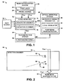
- FIG. 2 illustrates an example of a diagram that includes a detection chamber of an alkali beam cell in accordance with an aspect of the invention.
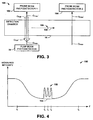
- FIG. 3 illustrates another example of a diagram that includes the detection chamber of the alkali beam cell in accordance with an aspect of the invention.
- FIG. 4 illustrates an example of an absorption spectrum in accordance with an aspect of the invention.
- FIG. 5 illustrates an example of a method for tuning a frequency reference of an atomic clock in accordance with an aspect of the invention.
- An alkali beam cell such as can be implemented in an atomic clock, includes a reservoir chamber and a detection chamber.
- the reservoir chamber can hold an alkali metal, such as Cesium (Cs), that evaporates in response to heat.
- the detection chamber can collect the evaporated alkali metal.
- a beam interrogation system can include a pump laser configured to generate an optical pump beam to illuminate the detection chamber.
- Evaporated alkali metal atoms that move through the detection chamber can thus be pumped to a specific hyperfine ground state by absorbing photons from the optical pump beam, and can be pumped back to the initial hyperfine ground state by emitting or absorbing photons in response to a microwave signal having a controlled frequency that corresponds to the hyperfine transition.
- the controlled frequency can be swept across a broad frequency range, such that an absorption spectrum can be obtained to ascertain a transition frequency of the evaporated alkali metal atoms that corresponds to an optimum absorption frequency having a very narrow linewidth.
- a local oscillator such as able to control the frequency of the microwave signal, can thus be locked to the transition frequency to obtain a frequency reference for the atomic clock.
- the evaporated alkali metal atoms can have a very random direction of motion through the detection chamber.
- absorption and emission of photons from evaporated alkali metal atoms that move in a non-orthogonal plane relative to the optical pump beam can result in a Doppler broadening of the optimum absorption frequency linewidth.
- the evaporated alkali metal atoms that move in the substantially orthogonal plane relative to the optical pump beam are "stationary" atoms and the evaporated alkali metal atoms that move in the non-orthogonal plane relative to the optical pump beam are "non-stationary”.
- the transition frequency may not be easily ascertainable based on the Doppler broadening of the apparent frequency of the microwave signal. Accordingly, the local oscillator frequency, and thus the frequency reference for the atomic clock, may not be accurate.
- the beam interrogation system can also generate at least one optical probe beam having the same wavelength as the pump beam.
- a probe beam can be configured as substantially co-linear with and in an opposite direction of the optical pump beam.
- the intensity of the optical probe beam can be measured to generate an intensity signal. Because the stationary evaporated alkali metal atoms are in resonance with both the optical pump beam and the optical probe beam at the same time, these evaporated alkali metal atoms can have a significantly greater probability of absorption of photons from the optical pump beam relative to the optical probe beam.
- the relative transmitted intensity of the optical probe beam can be significantly greater in response to a frequency of the microwave signal that is in resonance with the hyperfine state transition frequency of the stationary evaporated alkali metal atoms.
- the intensity signal can thus be combined with the absorption spectrum that is generated for the optical pump beam to provide a signal that is substantially only sensitive to the stationary atoms.
- the Doppler broadening of the optimum absorption frequency is substantially cancelled, thus resulting in a substantially accurate optimum absorption frequency.
- FIG. 1 illustrates an example of a diagram of an atomic clock system 10 in accordance with an aspect of the invention.
- the atomic clock system 10 can be implemented in a satellite application (e.g., global positioning satellite, or GPS) or any of a variety of other applications that require precise timing, small size, and a long operational life.
- the atomic clock system 10 includes an alkali beam cell 12 having a reservoir chamber 14 and a detection chamber 16.
- each of the reservoir and detection chambers 14 and 16 can be configured as glass chambers, such as fabricated from Pyrex®, and can be coupled via an aperture that includes one or more holes that connect the reservoir and detection chambers 14 and 16.
- the alkali beam cell 12 can be completely sealed.
- the reservoir chamber 14 of the alkali beam cell 12 can initially store a predetermined amount of an alkali metal, such as Cesium (Cs) or Rubidium (Rb).
- An external heat source 18 can apply heat (e.g., greater than or equal to approximately 80 degrees Celsius) to the alkali beam cell 12, such as along the side-walls of the reservoir chamber 14.
- the evaporated atoms of the alkali metal can travel from the reservoir chamber 14 to the detection chamber 16 at a substantially constant rate in a highly predictable manner with a controlled velocity profile into the detection chamber 16.
- an alkali metal beam is formed in the detection chamber 16, which can establish an accurate frequency reference for the atomic clock system 10, as described herein.
- the atomic clock system 10 also includes a beam interrogation system 20 that includes a pump laser 22 and at least one probe laser 24. Although the pump laser 22 and the at least one probe laser 24 are demonstrated as separate components, it is to be understood that the pump laser 22 and the at least one probe laser 24 can be generated from the same source.
- the pump laser 22 is configured to generate an optical pump signal O PMP that illuminates the detection chamber 16 to pump the evaporated alkali metal atoms from an initial hyperfine ground state into an excited hyperfine state based on the evaporated alkali metal atoms absorbing photons.
- the atomic clock system 10 also includes an optical detection system 26 that includes a microwave signal generator 28, a local oscillator 30, and a pump beam photodetector 32.
- the microwave signal generator 28 can generate a microwave signal MW that is directed to the detection chamber 16 to pump a specific hyperfine ground state transition, such that the evaporated alkali metal atoms can repopulate the initial hyperfine ground state.
- the frequency of the microwave signal MW can be controlled by the local oscillator 30.
- the local oscillator 30 can be tuned to sweep the microwave signal MW through a broad frequency range. Therefore, the pump beam photodetector 32 can monitor an intensity of the optical pump signal O PMP ' as it exits the detection chamber, such as generate an absorption frequency spectrum as a function of the frequency of the microwave signal MW. Accordingly, the absorption frequency spectrum can be implemented to determine a transition frequency, such as corresponding to an optimum absorption frequency of the evaporated alkali metal atoms. Therefore, the local oscillator 30 can be locked to the transition frequency to provide a substantially accurate frequency reference for the atomic clock system 10.
- FIG. 2 illustrates an example of a diagram 50 that includes the detection chamber 16 of the alkali beam cell 12 in accordance with an aspect of the invention.
- the diagram 50 demonstrates a first evaporated alkali metal atom 52 that is demonstrated as moving in an orthogonal plane relative to the optical pump beam O PMP , as demonstrated by an arrow 54.
- the first evaporated alkali metal atom 52 is therefore stationary with respect to the axis of the optical pump beam O PMP , such that it is a stationary evaporated alkali metal atom, as described herein.
- the diagram 50 also demonstrates a second evaporated alkali metal atom 56 that is demonstrated as moving in a non-orthogonal plane relative to the optical pump beam O PMP , as demonstrated by an arrow 58.
- the second evaporated alkali metal atom 56 is demonstrated as having a vector component of motion, demonstrated by an arrow 60, that is opposite the direction of the optical pump signal O PMP .
- the second evaporated alkali metal atom 56 is therefore non-stationary with respect to the axis of the optical pump beam O PMP , such that it is a non-stationary evaporated alkali metal atom, as described herein. It is to be understood that an evaporated alkali metal atom having a vector component in the same direction of optical pump signal O PMP likewise moves in a non-orthogonal plane relative to the optical pump signal O PMP .
- Rubidium atoms may have a resonance line having a natural linewidth of approximately 6 MHz.
- the Doppler broadened linewidth could be in a range of approximately 500-800 MHz.
- the frequency to which the local oscillator 30 is locked may not be accurately obtainable, thus resulting in an inaccurate frequency reference for the atomic clock system 10.
- the probe laser(s) 24 generate a respective at least one optical probe beam O PRB that likewise illuminate the detection chamber 16.
- the probe laser(s) 24 can generate a single optical probe beam O PRB that is substantially co-linear with and in an opposite direction of the optical pump beam O PMP .
- the probe laser(s) 24 can generate a pair of optical probe beams O PRB , one of which being substantially co-linear with and in an opposite direction of the optical pump beam O PMP , and the other being substantially parallel with and in the opposite direction of the optical pump beam O PMP and being spaced apart from the optical pump beam O PMP within the detection chamber 16.
- the optical probe beam(s) O PRB can have an intensity magnitude that is less than or approximately equal to the intensity magnitude of the optical pump beam O PMP .
- the optical probe beam O PRB can have an intensity that is approximately 10% of the intensity of the optical pump beam O PMP .
- the optical probe beam O PRB exits the detection chamber as a beam O PRB ' and is provided to a photodetection system 34 that includes a respective one or more photodetectors 36 configured to measure an intensity of the optical probe beams O PRB '.
- FIG. 3 illustrates another example of a diagram 100 that includes the detection chamber 16 of the alkali beam cell 12 in accordance with an aspect of the invention.
- the diagram 100 demonstrates the optical pump beam O PMP and a first optical probe beam O PRB1 that are substantially co-linear and propagate in opposite directions.
- the first optical probe beam O PRB1 exits the detection chamber 16 as the first optical probe beam O PRB1 ' and is provided to a first probe beam photodetector 102.
- the diagram 100 also demonstrates a second optical probe beam O PRB2 that is substantially parallel with the first optical probe beam O PRB1 and which is substantially spaced apart from the first optical probe beam O PRB1 and the optical pump beam O PMP within the length of the detection chamber 16.
- the second optical probe beam O PRB2 exits the detection chamber 16 as the second optical probe beam O PRB2 ' and is provided to a second probe beam photodetector 104.
- the first and second probe beam photodetectors 102 and 104 can correspond to the photodetectors 36 in the photodetection system 34 in the example of FIG. 1 .
- the diagram 100 further demonstrates a stationary evaporated alkali metal atom 106 that is demonstrated as moving in an orthogonal plane relative to the optical pump beam O PMP and the first and second optical probe beams O PRB1 and O PRB2 , as demonstrated by an arrow 108.
- the photodetection system 34 is configured to generate an intensity signal INT corresponding to the intensity of the one of more of the optical probe signals O PRB ' exiting the detection chamber 16.
- the intensity signal INT can correspond to an intensity of a single optical probe beam O PRB1 ', or can correspond to a difference between the intensities of the first and second optical probe beams O PRB1 ' and O PRB2 '.
- the intensity signal INT is provided to the optical detection system 26.
- the optical detection system 26 can be configured to combine the intensity signal INT with the absorption frequency spectrum that is generated for the optical pump signal O PMP ' across the tuned frequency of the local oscillator 30.
- the intensity signal INT can provide an indication to the optical detection system 26 of the photon absorption or emission of only the evaporated alkali metal atoms that move in the orthogonal plane relative to the optical pump beam O PMP .
- the intensity signal INT can be combined with a current output signal that is generated by the pump beam photodetector 32 and used to assemble the absorption frequency spectrum.
- the absorption frequency spectrum can be modified based on the intensity signal INT, such that the intensity signal INT can be substantially only sensitive to stationary atoms, thus cancelling the Doppler broadening of the transition frequency that corresponds to the optimum absorption frequency of the evaporated alkali metal atoms.
- the evaporated alkali metal atoms that move in the non-orthogonal planes relative to the optical pump beam O PMP can be in resonance with or can have a greater probability of absorption from one of the optical pump beam O PMP and the first optical probe beam O PRB1 and not the other based on the vector direction of movement of the atom, the tuning of the microwave frequency, and the wavelength of the light in the beams.
- the first probe beam photodetector 102 and the pump beam photodetector 32 each perceive substantially the same Doppler-broadened intensity response for each of the respective first optical probe beam O PRB1 ' and optical pump beam O PMP ' at frequencies of the microwave signal MW other than the transition frequency, or for wavelengths of the light beams which are not in resonance with the stationary atoms.
- stationary evaporated alkali metal atoms such as the atom 106
- stationary evaporated alkali metal atoms are in substantially equal resonance with both of the optical pump beam O PMP and the first optical probe beam O PRB1 . Therefore, at the transition frequency of the microwave signal MW corresponding to optimum absorption, the probability of absorption of photons from the first optical probe beam O PRB1 relative to the optical pump beam O PMP is significantly reduced.
- the first probe beam photodetector 102 perceives a substantially greater relative intensity of the first optical probe beam O PRB ' than at other frequencies than the transition frequency of the microwave signal MW.
- the first optical probe beam O PRB1 and the optical pump beam O PMP can have approximately the same intensity.
- the first probe beam photodetector 102 and the pump beam photodetector 32 each perceive substantially the same Doppler-broadened intensity response for each of the respective first optical probe beam O PRB1 ' and optical pump beam O PMP ' at frequencies of the microwave signal MW other than the transition frequency. Therefore, the first probe beam photodetector 102 and the pump beam photodetector 32 perceive approximately the same intensity across the frequency spectrum of the microwave signal MW other than the transition frequency.
- a stationary evaporated alkali metal atom has an approximately equal probability (e.g., approximately 50%) of absorbing photons from each of the first optical probe beam O PRB1 and the optical pump beam O PMP . Therefore, the measured intensity of the first optical probe beam O PRB1 ' leaving the detection chamber 16, which is substantially dependent on the interaction with the stationary atoms, is significantly changed at the transition frequency of the microwave signal MW than at other frequencies. Accordingly, the measurable change in intensity of the first optical probe beam O PRB1 ', as described by the intensity signal INT in the example of FIG.
- the microwave signal MW i.e., having a very narrow linewidth
- the transition frequency of the microwave signal MW i.e., having a very narrow linewidth
- the above example demonstrates cancellation of the Doppler broadening of the optimum absorption frequency based on only one optical probe beam (i.e., the first optical probe beam O PRB ).
- the optical detection system 26 can substantially cancel the Doppler broadening of the optimum absorption frequency based on both the first and second optical probe beams O PRB1 and O PRB2 .
- the second probe beam photodetector 104 can measure approximately the same Doppler broadened intensity response of the second optical probe beam O PRB2 ' as the optical pump beam O PMP ' across the entire frequency range of the microwave signal MW, including at the transition frequency of the microwave signal MW.
- the first optical probe beam O PRB1 ' can respond as described above, such that the measured intensity of the first optical probe beam O PRB1 ' can be significantly changed at the transition frequency of the microwave signal MW relative to other frequencies. Therefore, a measured difference between the intensities of the first and second optical probe beams O PRB1 ' and O PRB2 ' can be indicative of the transition frequency of the microwave signal MW for just the stationary atoms, without the Doppler broadening from the non-stationary alkali atoms.
- the intensity signal INT in the example of FIG. 1 can thus be provided as a signal describing the difference between the intensities of the first and second optical probe beams O PRB1 ' and O PRB2 '.
- the intensities of the first and second optical probe beams O PRB1 and O PRB2 can be set to a variety of intensities.
- the first optical probe beam O PRB1 can have an intensity that is less than or equal to the optical pump beam O PMP and the transition frequency of the microwave signal MW is determined base on changes in the measured intensity of the first optical probe beam O PRB1 ' across the absorption spectrum.
- the first and second optical probe beams O PRB1 and O PRB2 can have a substantially equal intensity and the transition frequency of the microwave signal MW is determined based on a difference between the measured intensities of the first and second optical probe beams O PRB1 ' and O PRB2 ' across the absorption spectrum.
- the first and second optical probe beams O PRB1 and O PRB2 can each have an intensity that is approximately 10% of the intensity of the optical pump beam O PMP .
- the intensity signal INT can be provided to the optical detection system 26 to mix the measured intensity of the first optical probe beam O PRB1 ' or of the first and second optical probe beams O PRB1 ' and O PRB2 ' with the measured intensity of the optical pump beam O PMP across the absorption spectrum.
- the absorption spectrum can demonstrate the absorption of the first optical probe beam O PRB ' as a function of the frequency of the microwave signal MW. Therefore, one or more peaks can be generated in the absorption spectrum across the range of frequencies of the microwave signal MW. Each of the one or more peaks can thus correspond to a narrow linewidth transition frequency of the evaporated alkali metal atoms resulting from the measurement of absorption of the stationary evaporated alkali metal atoms.
- FIG. 4 illustrates an example of an absorption spectrum 150 in accordance with an aspect of the invention.
- the absorption spectrum 150 demonstrates a combination of the measured intensity of pump beam photodetector 32 and the intensity signal INT, indicated in the example of FIG. 4 as "MEASURED INTENSITY".
- the intensity signal INT can be the measured intensity of the first optical probe beam O PRB1 ' or can be a difference between the second optical probe beam O PRB2 ' and the first optical probe beam O PRB1 '. Therefore, the MEASURED INTENSITY can be a current signal of a photodiode that includes a current output component of the pump beam photodetector 32 and the intensity signal INT.
- the absorption spectrum 150 plots the MEASURED INTENSITY as a function of frequency F of the microwave signal MW.
- the absorption spectrum 150 includes a frequency f 1 and a frequency f 2 between which the MEASURED INTENSITY is demonstrated as a dip. Therefore, the frequency range between the frequencies f 1 and f 2 represents the Doppler broadened optimum absorption frequency, as measured, for example, by the pump beam photodetector 32.
- the absorption spectrum 150 includes a plurality of peaks 152. Specifically, the peaks 152 include a first peak at a frequency f 3 , a second peak at a frequency f 4 , and a third peak at a frequency f 5 .
- Each of the peaks 152 can correspond to separate respective narrow linewidth transition frequencies of the evaporated alkali metal atoms, such as resulting from the combination of the intensity signal INT with the intensity of the optical pump signal O PMP ' as measured by the pump beam photodetector 32. Specifically, the peaks 152 are superimposed over the Doppler broadened optimum absorption frequency perceived by the pump beam photodetector 32, as indicated by the dashed line 154. As a result, the local oscillator 30 can be tuned to one of the frequencies f 3 , f 4 , or f 5 to obtain an accurate frequency reference for the atomic clock system 10, such as to improve accuracy of the atomic clock system 10 by one hundred times or more that of conventional atomic clocks.
- the absorption spectrum 150 is demonstrated simplistically, and is thus not necessarily in scale.
- the peaks 152 can be greater than one hundred times narrower than the Doppler broadened optimum absorption frequency between the frequencies f 1 and f 2 .
- the absorption spectrum 150 can also include one or more crossover peaks (not shown).
- the crossover peaks can be peaks that are positioned between a pair of the peaks 152 that result from non-stationary evaporated alkali metal atoms that are in substantially exact resonance with one of the optical pump beam O PMP and the first optical probe beam O PRB1 and not in resonance with the other of the optical pump beam O PMP and the first optical probe beam O PRB1 .
- the crossover peaks can correspond to non-stationary evaporated alkali metal atoms that are Doppler-shifted up or Doppler-shifted down relative to one of the optical pump beam O PMP and the first optical probe beam O PRB1 to be in resonance with one of the neighboring peaks 152.
- Crossover peaks can, however, be easily identified and disregarded for purposes of locking the frequency of the local oscillator 30 to the one or more transition frequencies represented by the peaks 152.
- FIG. 5 a methodology in accordance with various aspects of the present invention will be better appreciated with reference to FIG. 5 . While, for purposes of simplicity of explanation, the methodologies of FIG. 5 are shown and described as executing serially, it is to be understood and appreciated that the present invention is not limited by the illustrated order, as some aspects could, in accordance with the present invention, occur in different orders and/or concurrently with other aspects from that shown and described herein. Moreover, not all illustrated features may be required to implement a methodology in accordance with an aspect of the present invention.
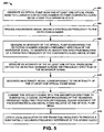
- FIG. 5 illustrates an example of a method 200 for tuning a frequency reference of an atomic clock in accordance with an aspect of the invention.
- an optical pump beam and at least one optical probe beam are generated that are configured to illuminate the detection chamber to pump evaporated alkali metal atoms into a hyperfine state as they are collected in a detection chamber of an alkali beam cell.
- the evaporated alkali metal atoms can be Cs or Rb.
- the at least one optical probe beam can be a single optical probe beam that is substantially co-linear with and in an opposite direction of the optical pump signal, or could include a second optical probe signal that is substantially parallel with the optical pump beam and spaced apart from the optical pump beam within the volume of the detection chamber.
- a microwave signal having a controlled frequency is provided to the detection chamber.
- the frequency of the microwave signal can be controlled by a local oscillator, and can be swept across a broad frequency range to obtain an absorption spectrum.
- the microwave signal can be configured to stimulate emission of photons absorbed by the evaporated alkali metal atoms as a result of the optical pumping.
- an intensity of the optical pump beam exiting the detection chamber is measured across a frequency spectrum of the microwave signal to generate an absorption spectrum indicative of a transition frequency of the microwave signal corresponding to optimum photon absorption of the evaporated alkali metal atoms.
- the optimum photo absorption spectrum can be Doppler-broadened based on the emission of photons of non-stationary evaporated alkali metal atoms that move in a non-orthogonal plane relative to the optical pump beam.
- an intensity of the at least one optical probe beam exiting the detection chamber is measured across the frequency spectrum of the microwave signal.
- the measurement of the at least one optical probe beam can result from the output signal of an associated photodetector.
- an intensity signal corresponding to the intensity of the at least one optical probe beam is generated.
- the intensity signal can correspond to the intensity of a single optical probe beam or can represent a difference in intensity of a pair of optical probe beams.
- the intensity signal is combined with the absorption spectrum to substantially cancel Doppler broadening of the transition frequency resulting from non-orthogonal planar movement of the evaporated alkali metal atoms relative to the optical pump beam and the at least one optical probe beam.
- the intensity signal can indicate when the substantially co-linear optical probe beam has a substantially higher intensity in the frequency range of the microwave signal, thus corresponding to the transition frequency of the stationary evaporated alkali metal atoms.
- a local oscillator is locked to the transition frequency to provide a substantially accurate frequency reference of the atomic clock.
Landscapes
- Life Sciences & Earth Sciences (AREA)
- Ecology (AREA)
- Physics & Mathematics (AREA)
- General Physics & Mathematics (AREA)
- Stabilization Of Oscillater, Synchronisation, Frequency Synthesizers (AREA)
- Investigating Or Analysing Materials By Optical Means (AREA)
Claims (13)
- Atomuhrensystem (10; 100) mit:einer Alkalistrahlzelle (12), die eine Reservoirkammer (14), die dazu ausgebildet ist, ein Alkalimetall zu verdampfen, und eine Erfassungskammer (16), die dazu ausgebildet ist, verdampfte Alkalimetallatome (52; 56; 106) zu sammeln, aufweist;einem Strahlenabfragesystem (20), das dazu ausgebildet ist, einen optischen Pumpstrahl (OPMP) und mindestens einen optischen Messstrahl (OPRB) zu erzeugen, die die Erfassungskammer (16) beleuchten, um die verdampften Alkalimetallatome (52, 56; 106) zu pumpen, wenn sie in der Erfassungskammer (16) gesammelt werden;einem optischen Erfassungssystem (26), das dazu ausgebildet ist, der Erfassungskammer (16) ein Mikrowellensignal (MW) mit einer gesteuerten Frequenz zuzuführen und eine Intensität des optischen Pumpstrahls (OPMP') zu messen, der die Erfassungskammer (16) verlässt, um eine Übergangsfrequenz des Mikrowellensignals (MW) zu bestimmen, die der optimalen Photonenabsorption der verdampften Alkalimetallatome (52, 56; 106) entspricht; undeinem Photodetektionssystem (34), das dazu ausgebildet ist, eine Intensität des mindestens einen optischen Messstrahls (OPRB') zu messen, der die Erfassungskammer (16) verlässt, und ein Intensitätssignal (INT) zu erzeugen, wobei das Intensitätssignal (INT) dem optischen Erfassungssystem zugeführt wird,wobei das optische Erfassungssystem (26) aufweist:- eine Mikrowellensignalerzeugungseinrichtung (28), die dazu ausgebildet ist, das Mikrowellensignal (MW) zu erzeugen;- einen lokalen Oszillator (30), der dazu ausgebildet ist, die Frequenz des Mikrowellensignals (MW) so zu steuern, dass sie über einen breiten Frequenzbereich gewobbelt wird; und- einen Pumpstrahlphotodetektor (32), der dazu ausgebildet ist, ein Absorptionsspektrum als Reaktion auf die gewobbelte Frequenz der Mikrowellensignalerzeugungseinrichtung (28) zu erzeugen,und wobei das optische Erfassungssystem (26) dazu ausgebildet ist, das Intensitätssignal (INT) mit dem Absorptionsspektrum zu kombinieren.
- System nach Anspruch 1, wobei der mindestens eine optische Messstrahl als ein erster optischer Messstrahl (OPRB1) und ein zweiter optischer Messstrahl (OPRB2) ausgebildet ist, und/oder
wobei der mindestens eine optische Messstrahl (OPRB1, OPRB2) mit im Wesentlichen geringerer Intensität erzeugt wird als der optische Pumpstrahl (OPMP), und/oder wobei der mindestens eine optische Messstrahl (OPRB1, PPRB2) einen einzelnen optischen Messstrahl (OPRB1) aufweist, der im Wesentlichen kollinear zu dem optischen Pumpstrahl (OPMP) ist und eine zu diesem entgegengesetzte Richtung aufweist. - System nach Anspruch 2, wobei das Photodetektionssystem (102, 104) einen ersten Photodetektor (102), der dazu ausgebildet ist, eine dem ersten optischen Messstrahl (OPRB1) entsprechende erste Intensität zu messen, und einen zweiten Photodetektor (104), der dazu ausgebildet ist, eine dem zweiten optischen Messstrahl (OPRB2) entsprechende zweite Intensität zu messen, aufweist, wobei das Intensitätssignal (INT) als ein Unterschied zwischen der ersten Intensität und der zweiten Intensität erzeugt wird, und/oder
wobei der erste optische Messstrahl (OPRB1) im Wesentlichen kollinear zu dem optischen Pumpstrahl (OPMP) ist und eine zu diesem entgegengesetzte Richtung aufweist, und wobei der zweite optische Messstrahl (OPRB2) innerhalb des Volumens der Erfassungskammer (16) im Wesentlichen parallel zu dem optischen Pumpstrahl (OPMP) und von dem optischen Pumpstrahl (OPMP) beabstandet vorgesehen ist und/oder
wobei der einzelne optische Messstrahl eine Intensität hat, die geringer oder ungefähr gleich der Intensität des optischen Pumpstrahls (OPMP) ist. - System nach Anspruch 1, wobei das Intensitätssignal (INT) dem Pumpstrahlphotodetektor (32) zugeführt wird, um mindestens eine Spitze (152) auf dem Absorptionsspektrum zu erzeugen, die der Übergangsfrequenz des Mikrowellensignals (MW) für die verdampften Alkalimetallatome (52; 106) mit einer orthogonalen planaren Bewegung relativ zu dem optischen Pumpstrahl (OPMP) entspricht.
- System nach Anspruch 1, wobei das optische Erfassungssystem (26) ferner dazu ausgebildet ist, den lokalen Oszillator (30) auf der Übergangsfrequenz zu verriegeln, um eine im Wesentlichen genaue Frequenzreferenz für das Atomuhrensystem (10; 100) liefern.
- Verfahren zum Abstimmen einer Frequenzreferenz einer Atomuhr (10; 100), wobei das Verfahren beinhaltet:Erzeugen eines optischen Pumpstrahls (OPMP) und mindestens eines optischen Messstrahls (OPRB), die dazu ausgebildet sind, eine Erfassungskammer (16) einer Alkalistrahlzelle zu beleuchten, um verdampfte Alkalimetallatome (52, 56; 106) in einen Hyperfein-Zustsnd zu pumpen, wenn sie in der Erfassungskammer (16) gesammelt werden;Liefern eines Mikrowellensignals (MW) mit einer gesteuerten Frequenz an die Erfassungskammer (16);Messen einer Intensität des optischen Pumpstrahls (OPMP'), der die Erfassungskammer (16) verlässt, über ein Frequenzspektrum des Mikrowellensignals (MW), um ein Absorptionsspektrum zu erzeugen, das eine Übergangsfrequenz des Mikrowellensignals (MW) angibt, die einer optimalen Photonenabsorption der verdampften Alkalimetallatome (52, 56; 106) entspricht;Messen einer Intensität des mindestens einen optischen Messstrahls (OPRB'), der die Erfassungskammer (16) verlässt, über das Frequenzspektrum des Mikrowellensignals (MW);Erzeugen eines Intensitätssignals (INT), das der Intensität des mindestens einen optischen Messstrahls (OPRB') entspricht;Kombinieren des Intensitätssignals (INT) mit dem Absorptionsspektrum; undVerriegeln eines lokalen Oszillators (30) auf der Übergangsfrequenz, um eine im Wesentlichen genaue Frequenzreferenz der Atomuhr zu liefern.
- Verfahren nach Anspruch 6, wobei das Erzeugen des mindestens einen optischen Messstrahls beinhaltet:Erzeugen eines ersten optischen Messstrahls (OPRB1), der im Wesentlichen kollinear zu dem optischen Pumpstrahl (OPMP) ist und eine zu diesem entgegengesetzte Richtung aufweist; undErzeugen eines zweiten optischen Messstrahls (OPRB2), der innerhalb des Volumens der Erfassungskammer (16) im Wesentlichen parallel zu dem optischen Pumpstrahl (OPMP) und von dem optischen Pumpstrahl (OPMP) beabstandet vorgesehen ist, und/oderwobei das Erzeugen des mindestens einen optischen Messstrahls (OPRB) das Erzeugen des mindestens einen optischen Messstrahls (OPRB1) mit einer Intensität beinhaltet, die im Wesentlichen geringer als eine Intensität des optischen Pumpstrahls (OPMP) ist, und/oderwobei das Erzeugen des mindestens einen optischen Messstrahls (OPRB1) das Erzeugen eines einzelnen optischen Messstrahls beinhaltet, der im Wesentlichen kollinear zu dem optischen Pumpstrahl (OPMP) ist und eine zu diesem entgegengesetzte Richtung aufweist.
- Verfahren nach Anspruch 7, wobei das Messen der Intensität des mindestens einen optischen Messstrahls (OPRB1, OPRB2) das Messen einer dem ersten optischen Messstrahl (OPRB1) entsprechenden ersten Intensität und das Messen einer dem zweiten optischen Messstrahl (OPRB2) entsprechenden zweiten Intensität beinhaltet, und wobei das Erzeugen des Intensitätssignals (INT) das Erzeugen des Intensitätssignals (INT) als ein Unterschied zwischen der ersten Intensität und der zweiten Intensität beinhaltet.
- Verfahren nach Anspruch 8, wobei das Kombinieren des Intensitätssignals (INT) mit dem Absorptionsspektrum das Erzeugen mindestens einer Spitze auf dem Absorptionsspektrum beinhaltet, die der Übergangsfrequenz des Mikrowellensignals für die verdampften Alkalimetallatome (52; 106) mit einer orthogonalen planaren Bewegung relativ zu dem optischen Pumpstrahl (OPMP) entspricht.
- Verfahren nach Anspruch 8, wobei das Erzeugen des einzelnen optischen Messstrahls (OPRB) das Erzeugen des einzelnen optischen Messstrahls (OPRB) mit einer Intensität beinhaltet, die geringer oder ungefähr gleich der Intensität des optischen Pumpstrahls (OPMP) ist.
- Atomuhrensystem (10, 100) mit:einer Einrichtung zum Erzeugen eines optischen Pumpstrahls (OPMP), der eine Erfassungskammer (16) einer Alkalistrahlzelle beleuchtet, um verdampfte Alkalimetallatome (52, 56; 106) in einen Hyperfein-Zustand zu pumpen, wenn sie in der Erfassungskammer (16) gesammelt werden;einer Einrichtung zum Erzeugen eines optischen Messstrahls (OPRB), der im Wesentlichen kollinear zu dem optischen Pumpstrahl (OPMP) ist und eine zu diesem entgegengesetzte Richtung aufweist;einer Einrichtung zum Liefern eines Mikrowellensignals (MW) mit einer gesteuerten Frequenz an die Erfassungskammer (16);einer Einrichtung zum Messen einer Intensität des optischen Pumpstrahls (OPMP), der die Erfassungskammer (16) verlässt, über ein Frequenzspektrum des Mikrowellensignals (MW), um ein Absorptionsspektrum zu erzeugen, das eine Übergangsfrequenz des Mikrowellensignals (MW) angibt, die einer optimalen Photonenabsorption der verdampften Alkalimetallatome entspricht; undeiner Einrichtung zum Messen einer Intensität des optischen Messstrahls (OPRB'), der die Erfassungskammer (16) verlässt, über das Frequenzspektrum des Mikrowellensignals (MW) und zum Erzeugen eines Intensitätssignals (INT), das der Intensität des mindestens einen optischen Messstrahls (OPRB) entspricht, wobei das Intensitätssignal (INT) der Einrichtung zum Messen der Intensität des optischen Pumpstrahls (OPMP') zugeführt wird,wobei die Einrichtung zum Messen einer Intensität des optischen Pumpstrahls (OPMP') aufweist:- eine Mikrowellensignalerzeugungseinrichtung (28), die dazu ausgebildet ist, das Mikrowellensignal (MW) zu erzeugen;- einen lokalen Oszillator (30), der dazu ausgebildet ist, die Frequenz des Mikrowellensignals (MW) so zu steuern, dass sie über einen breiten Frequenzbereich gewobbelt wird; und- einen Pumpstrahlphotodetektor (32), der dazu ausgebildet ist, ein Absorptionsspektrum als Reaktion auf die gewobbelte Frequenz der Mikrowellensignalerzeugungseinrichtung (28) zu erzeugen,und wobei das optische Erfassungssystem (26) dazu ausgebildet ist, das Intensitätssignal (INT) mit dem Absorptionsspektrum zu kombinieren.
- System nach Anspruch 11, ferner aufweisend:eine Einrichtung zum Erzeugen eines zweiten optischen Messstrahls (OPRB2), der innerhalb des Volumens der Erfassungskammer (16) von dem optischen Pumpstrahl (OPMP) beabstandet ist; undeine Einrichtung zum Messen einer Intensität des zweiten optischen Messstrahls (OPRB2), der die Erfassungskammer (16) verlässt, über das Frequenzspektrum des Mikrowellensignals (MW);wobei das Intensitätssignal (INT) einen Unterschied zwischen der Intensität des ersten optischen Messstrahls (OPRB1') und der Intensität des zweiten optischen Messstrahls (OPRB2') angibt.
- System nach Anspruch 11, ferner aufweisend eine Einrichtung zum Verriegeln eines lokalen Oszillators auf der Übergangsfrequenz, um eine im Wesentlichen genaue Frequenzreferenz des Atomuhrensystems (10; 100) zu liefern.
Applications Claiming Priority (1)
| Application Number | Priority Date | Filing Date | Title |
|---|---|---|---|
| US12/534,615 US7965148B2 (en) | 2009-08-03 | 2009-08-03 | Atomic frequency clock systems and methods |
Publications (3)
| Publication Number | Publication Date |
|---|---|
| EP2282243A2 EP2282243A2 (de) | 2011-02-09 |
| EP2282243A3 EP2282243A3 (de) | 2011-11-23 |
| EP2282243B1 true EP2282243B1 (de) | 2013-11-13 |
Family
ID=43125536
Family Applications (1)
| Application Number | Title | Priority Date | Filing Date |
|---|---|---|---|
| EP10008101.7A Active EP2282243B1 (de) | 2009-08-03 | 2010-08-03 | Atomuhrsystem und Frequenzabstimmungsverfahren für ein solches System |
Country Status (3)
| Country | Link |
|---|---|
| US (1) | US7965148B2 (de) |
| EP (1) | EP2282243B1 (de) |
| JP (1) | JP5266284B2 (de) |
Families Citing this family (10)
| Publication number | Priority date | Publication date | Assignee | Title |
|---|---|---|---|---|
| US8487729B2 (en) * | 2009-02-02 | 2013-07-16 | Northrop Grumman Guidance & Electronics | Magnetic solenoid for generating a substantially uniform magnetic field |
| US9062973B2 (en) * | 2011-01-31 | 2015-06-23 | Northrop Grumman Guidance And Electronics Company, Inc. | Atom beam gyroscope |
| CN103185889A (zh) * | 2011-12-31 | 2013-07-03 | 上海航天测控通信研究所 | 高稳定时间与频率生成系统 |
| CN102799103B (zh) * | 2012-08-10 | 2014-12-17 | 中国科学院上海光学精密机械研究所 | 具有高对比度鉴频信号的铷原子钟 |
| US10539929B2 (en) * | 2016-10-11 | 2020-01-21 | Northrop Grumman Systems Corporation | Atomic clock system |
| CN106444343B (zh) * | 2016-11-28 | 2018-09-07 | 中国科学院武汉物理与数学研究所 | 一种微型原子钟数字控制电路装置及方法 |
| US10782368B2 (en) | 2017-05-31 | 2020-09-22 | Northrop Grumman Systems Corporation | Pulsed-beam atomic magnetometer system |
| US11133117B2 (en) | 2019-05-08 | 2021-09-28 | Northrop Grumman Systems Corporation | Atomic interferometer system |
| US11079230B2 (en) | 2019-05-10 | 2021-08-03 | Northrop Grumman Systems Corporation | Fiber-optic gyroscope (FOG) assembly |
| CN111045008B (zh) * | 2020-01-15 | 2023-06-09 | 深圳市华讯方舟微电子科技有限公司 | 基于展宽计算的车载毫米波雷达目标识别方法 |
Family Cites Families (8)
| Publication number | Priority date | Publication date | Assignee | Title |
|---|---|---|---|---|
| US4323860A (en) * | 1980-03-27 | 1982-04-06 | The United States Of America As Represented By The Secretary Of The Air Force | Laser excited molecular beam time and frequency standard |
| JPH0263321A (ja) * | 1988-08-30 | 1990-03-02 | Yokogawa Electric Corp | 周波数標準器 |
| JPH0783265B2 (ja) * | 1989-08-21 | 1995-09-06 | 新技術事業団 | レーザ励起ルビジウム原子発振器 |
| US5657340A (en) * | 1996-04-19 | 1997-08-12 | The Aerospace Corporation | Rubidium atomic clock with fluorescence optical pumping and method using same |
| US6320472B1 (en) * | 1999-01-26 | 2001-11-20 | Kernco, Inc. | Atomic frequency standard |
| JP2009129955A (ja) * | 2007-11-20 | 2009-06-11 | Epson Toyocom Corp | 光学系及び原子発振器 |
| EP2131500A3 (de) * | 2008-06-02 | 2012-03-07 | SEPA - Sistemi Elettronici Per Automazione S.P.A. | Atomstrahlröhre mit gegenläufigen Licht- oder Atomstrahlen |
| US7893780B2 (en) * | 2008-06-17 | 2011-02-22 | Northrop Grumman Guidance And Electronic Company, Inc. | Reversible alkali beam cell |
-
2009
- 2009-08-03 US US12/534,615 patent/US7965148B2/en active Active
-
2010
- 2010-08-02 JP JP2010174052A patent/JP5266284B2/ja active Active
- 2010-08-03 EP EP10008101.7A patent/EP2282243B1/de active Active
Also Published As
| Publication number | Publication date |
|---|---|
| US20110025425A1 (en) | 2011-02-03 |
| EP2282243A2 (de) | 2011-02-09 |
| JP2011035402A (ja) | 2011-02-17 |
| EP2282243A3 (de) | 2011-11-23 |
| US7965148B2 (en) | 2011-06-21 |
| JP5266284B2 (ja) | 2013-08-21 |
Similar Documents
| Publication | Publication Date | Title |
|---|---|---|
| EP2282243B1 (de) | Atomuhrsystem und Frequenzabstimmungsverfahren für ein solches System | |
| Hu et al. | Sr atom interferometry with the optical clock transition as a gravimeter and a gravity gradiometer | |
| US8780948B2 (en) | Precision photonic oscillator and method for generating an ultra-stable frequency reference using a two-photon rubidium transition | |
| US5847817A (en) | Method for extending range and sensitivity of a fiber optic micro-doppler ladar system and apparatus therefor | |
| EP2154586B1 (de) | Kaltatomen-Atomuhr | |
| US9062973B2 (en) | Atom beam gyroscope | |
| EP3752792B1 (de) | Geschwindigkeitsselektiver thermischer atomstrahl-trägheitssensor | |
| Udem et al. | Femtosecond optical frequency combs | |
| Terra et al. | An ultra-stable optical frequency standard for telecommunication purposes based upon the 5S1/2→ 5D5/2 two-photon transition in Rubidium | |
| US11133117B2 (en) | Atomic interferometer system | |
| EP4080163B1 (de) | Lichtquellenvorrichtung für faseroptischen kreisel | |
| JP4793675B2 (ja) | 距離測定装置 | |
| CN108474808B (zh) | 用于冷原子惯性传感器的激光源 | |
| Kumarakrishnan et al. | Ground-state grating echoes from Rb vapor at room temperature | |
| Jana et al. | Progress towards the development of a portable all-optical atomic clock based on a two-photon transition in warm atomic vapor | |
| Keliehor | Technology development for a compact rubidium optical frequency reference | |
| Morin et al. | What narrow-linewidth semiconductor lasers can do for defense and security? | |
| Kozma et al. | Metrology Under Control: Fiber Technology Shoots Frequency Combs to Outer Space | |
| Rauschenbeutel et al. | Six-beam optical lattice with intrinsically stable time phases | |
| Kozlova et al. | Cs buffer gas collisional frequency shift: method and preliminary measurements | |
| Lee et al. | Current status of an atomic gravimeter developing at KRISS | |
| Baumann | Rapid, High Resolution Frequency Comb Measurements | |
| Minamisawa et al. | THz wave generation using frequency stabilized laser diodes |
Legal Events
| Date | Code | Title | Description |
|---|---|---|---|
| PUAI | Public reference made under article 153(3) epc to a published international application that has entered the european phase |
Free format text: ORIGINAL CODE: 0009012 |
|
| 17P | Request for examination filed |
Effective date: 20100803 |
|
| AK | Designated contracting states |
Kind code of ref document: A2 Designated state(s): AL AT BE BG CH CY CZ DE DK EE ES FI FR GB GR HR HU IE IS IT LI LT LU LV MC MK MT NL NO PL PT RO SE SI SK SM TR |
|
| AX | Request for extension of the european patent |
Extension state: BA ME RS |
|
| PUAL | Search report despatched |
Free format text: ORIGINAL CODE: 0009013 |
|
| AK | Designated contracting states |
Kind code of ref document: A3 Designated state(s): AL AT BE BG CH CY CZ DE DK EE ES FI FR GB GR HR HU IE IS IT LI LT LU LV MC MK MT NL NO PL PT RO SE SI SK SM TR |
|
| AX | Request for extension of the european patent |
Extension state: BA ME RS |
|
| RIC1 | Information provided on ipc code assigned before grant |
Ipc: G04F 5/14 20060101AFI20111019BHEP |
|
| GRAP | Despatch of communication of intention to grant a patent |
Free format text: ORIGINAL CODE: EPIDOSNIGR1 |
|
| INTG | Intention to grant announced |
Effective date: 20130411 |
|
| RIN1 | Information on inventor provided before grant (corrected) |
Inventor name: LARSEN, MICHAEL S. |
|
| GRAS | Grant fee paid |
Free format text: ORIGINAL CODE: EPIDOSNIGR3 |
|
| GRAP | Despatch of communication of intention to grant a patent |
Free format text: ORIGINAL CODE: EPIDOSNIGR1 |
|
| GRAA | (expected) grant |
Free format text: ORIGINAL CODE: 0009210 |
|
| INTG | Intention to grant announced |
Effective date: 20130917 |
|
| AK | Designated contracting states |
Kind code of ref document: B1 Designated state(s): AL AT BE BG CH CY CZ DE DK EE ES FI FR GB GR HR HU IE IS IT LI LT LU LV MC MK MT NL NO PL PT RO SE SI SK SM TR |
|
| REG | Reference to a national code |
Ref country code: GB Ref legal event code: FG4D |
|
| REG | Reference to a national code |
Ref country code: CH Ref legal event code: EP |
|
| REG | Reference to a national code |
Ref country code: AT Ref legal event code: REF Ref document number: 640815 Country of ref document: AT Kind code of ref document: T Effective date: 20131215 |
|
| REG | Reference to a national code |
Ref country code: IE Ref legal event code: FG4D |
|
| REG | Reference to a national code |
Ref country code: DE Ref legal event code: R096 Ref document number: 602010011669 Country of ref document: DE Effective date: 20140109 |
|
| REG | Reference to a national code |
Ref country code: NL Ref legal event code: VDEP Effective date: 20131113 |
|
| REG | Reference to a national code |
Ref country code: AT Ref legal event code: MK05 Ref document number: 640815 Country of ref document: AT Kind code of ref document: T Effective date: 20131113 |
|
| REG | Reference to a national code |
Ref country code: LT Ref legal event code: MG4D |
|
| PG25 | Lapsed in a contracting state [announced via postgrant information from national office to epo] |
Ref country code: FI Free format text: LAPSE BECAUSE OF FAILURE TO SUBMIT A TRANSLATION OF THE DESCRIPTION OR TO PAY THE FEE WITHIN THE PRESCRIBED TIME-LIMIT Effective date: 20131113 Ref country code: LT Free format text: LAPSE BECAUSE OF FAILURE TO SUBMIT A TRANSLATION OF THE DESCRIPTION OR TO PAY THE FEE WITHIN THE PRESCRIBED TIME-LIMIT Effective date: 20131113 Ref country code: NL Free format text: LAPSE BECAUSE OF FAILURE TO SUBMIT A TRANSLATION OF THE DESCRIPTION OR TO PAY THE FEE WITHIN THE PRESCRIBED TIME-LIMIT Effective date: 20131113 Ref country code: HR Free format text: LAPSE BECAUSE OF FAILURE TO SUBMIT A TRANSLATION OF THE DESCRIPTION OR TO PAY THE FEE WITHIN THE PRESCRIBED TIME-LIMIT Effective date: 20131113 Ref country code: NO Free format text: LAPSE BECAUSE OF FAILURE TO SUBMIT A TRANSLATION OF THE DESCRIPTION OR TO PAY THE FEE WITHIN THE PRESCRIBED TIME-LIMIT Effective date: 20140213 Ref country code: SE Free format text: LAPSE BECAUSE OF FAILURE TO SUBMIT A TRANSLATION OF THE DESCRIPTION OR TO PAY THE FEE WITHIN THE PRESCRIBED TIME-LIMIT Effective date: 20131113 Ref country code: IS Free format text: LAPSE BECAUSE OF FAILURE TO SUBMIT A TRANSLATION OF THE DESCRIPTION OR TO PAY THE FEE WITHIN THE PRESCRIBED TIME-LIMIT Effective date: 20140313 |
|
| PG25 | Lapsed in a contracting state [announced via postgrant information from national office to epo] |
Ref country code: CY Free format text: LAPSE BECAUSE OF FAILURE TO SUBMIT A TRANSLATION OF THE DESCRIPTION OR TO PAY THE FEE WITHIN THE PRESCRIBED TIME-LIMIT Effective date: 20131113 Ref country code: ES Free format text: LAPSE BECAUSE OF FAILURE TO SUBMIT A TRANSLATION OF THE DESCRIPTION OR TO PAY THE FEE WITHIN THE PRESCRIBED TIME-LIMIT Effective date: 20131113 Ref country code: AT Free format text: LAPSE BECAUSE OF FAILURE TO SUBMIT A TRANSLATION OF THE DESCRIPTION OR TO PAY THE FEE WITHIN THE PRESCRIBED TIME-LIMIT Effective date: 20131113 Ref country code: LV Free format text: LAPSE BECAUSE OF FAILURE TO SUBMIT A TRANSLATION OF THE DESCRIPTION OR TO PAY THE FEE WITHIN THE PRESCRIBED TIME-LIMIT Effective date: 20131113 Ref country code: BE Free format text: LAPSE BECAUSE OF FAILURE TO SUBMIT A TRANSLATION OF THE DESCRIPTION OR TO PAY THE FEE WITHIN THE PRESCRIBED TIME-LIMIT Effective date: 20131113 |
|
| PG25 | Lapsed in a contracting state [announced via postgrant information from national office to epo] |
Ref country code: PT Free format text: LAPSE BECAUSE OF FAILURE TO SUBMIT A TRANSLATION OF THE DESCRIPTION OR TO PAY THE FEE WITHIN THE PRESCRIBED TIME-LIMIT Effective date: 20140313 |
|
| PG25 | Lapsed in a contracting state [announced via postgrant information from national office to epo] |
Ref country code: EE Free format text: LAPSE BECAUSE OF FAILURE TO SUBMIT A TRANSLATION OF THE DESCRIPTION OR TO PAY THE FEE WITHIN THE PRESCRIBED TIME-LIMIT Effective date: 20131113 |
|
| REG | Reference to a national code |
Ref country code: DE Ref legal event code: R097 Ref document number: 602010011669 Country of ref document: DE |
|
| PG25 | Lapsed in a contracting state [announced via postgrant information from national office to epo] |
Ref country code: RO Free format text: LAPSE BECAUSE OF FAILURE TO SUBMIT A TRANSLATION OF THE DESCRIPTION OR TO PAY THE FEE WITHIN THE PRESCRIBED TIME-LIMIT Effective date: 20131113 Ref country code: CZ Free format text: LAPSE BECAUSE OF FAILURE TO SUBMIT A TRANSLATION OF THE DESCRIPTION OR TO PAY THE FEE WITHIN THE PRESCRIBED TIME-LIMIT Effective date: 20131113 Ref country code: SK Free format text: LAPSE BECAUSE OF FAILURE TO SUBMIT A TRANSLATION OF THE DESCRIPTION OR TO PAY THE FEE WITHIN THE PRESCRIBED TIME-LIMIT Effective date: 20131113 Ref country code: PL Free format text: LAPSE BECAUSE OF FAILURE TO SUBMIT A TRANSLATION OF THE DESCRIPTION OR TO PAY THE FEE WITHIN THE PRESCRIBED TIME-LIMIT Effective date: 20131113 |
|
| PLBE | No opposition filed within time limit |
Free format text: ORIGINAL CODE: 0009261 |
|
| STAA | Information on the status of an ep patent application or granted ep patent |
Free format text: STATUS: NO OPPOSITION FILED WITHIN TIME LIMIT |
|
| PG25 | Lapsed in a contracting state [announced via postgrant information from national office to epo] |
Ref country code: DK Free format text: LAPSE BECAUSE OF FAILURE TO SUBMIT A TRANSLATION OF THE DESCRIPTION OR TO PAY THE FEE WITHIN THE PRESCRIBED TIME-LIMIT Effective date: 20131113 |
|
| 26N | No opposition filed |
Effective date: 20140814 |
|
| REG | Reference to a national code |
Ref country code: DE Ref legal event code: R097 Ref document number: 602010011669 Country of ref document: DE Effective date: 20140814 |
|
| PG25 | Lapsed in a contracting state [announced via postgrant information from national office to epo] |
Ref country code: SI Free format text: LAPSE BECAUSE OF FAILURE TO SUBMIT A TRANSLATION OF THE DESCRIPTION OR TO PAY THE FEE WITHIN THE PRESCRIBED TIME-LIMIT Effective date: 20131113 |
|
| PG25 | Lapsed in a contracting state [announced via postgrant information from national office to epo] |
Ref country code: LU Free format text: LAPSE BECAUSE OF FAILURE TO SUBMIT A TRANSLATION OF THE DESCRIPTION OR TO PAY THE FEE WITHIN THE PRESCRIBED TIME-LIMIT Effective date: 20140803 Ref country code: MC Free format text: LAPSE BECAUSE OF FAILURE TO SUBMIT A TRANSLATION OF THE DESCRIPTION OR TO PAY THE FEE WITHIN THE PRESCRIBED TIME-LIMIT Effective date: 20131113 |
|
| REG | Reference to a national code |
Ref country code: CH Ref legal event code: PL |
|
| PG25 | Lapsed in a contracting state [announced via postgrant information from national office to epo] |
Ref country code: LI Free format text: LAPSE BECAUSE OF NON-PAYMENT OF DUE FEES Effective date: 20140831 Ref country code: CH Free format text: LAPSE BECAUSE OF NON-PAYMENT OF DUE FEES Effective date: 20140831 |
|
| REG | Reference to a national code |
Ref country code: IE Ref legal event code: MM4A |
|
| PG25 | Lapsed in a contracting state [announced via postgrant information from national office to epo] |
Ref country code: IE Free format text: LAPSE BECAUSE OF NON-PAYMENT OF DUE FEES Effective date: 20140803 |
|
| PG25 | Lapsed in a contracting state [announced via postgrant information from national office to epo] |
Ref country code: SM Free format text: LAPSE BECAUSE OF FAILURE TO SUBMIT A TRANSLATION OF THE DESCRIPTION OR TO PAY THE FEE WITHIN THE PRESCRIBED TIME-LIMIT Effective date: 20131113 |
|
| PG25 | Lapsed in a contracting state [announced via postgrant information from national office to epo] |
Ref country code: MT Free format text: LAPSE BECAUSE OF FAILURE TO SUBMIT A TRANSLATION OF THE DESCRIPTION OR TO PAY THE FEE WITHIN THE PRESCRIBED TIME-LIMIT Effective date: 20131113 Ref country code: GR Free format text: LAPSE BECAUSE OF FAILURE TO SUBMIT A TRANSLATION OF THE DESCRIPTION OR TO PAY THE FEE WITHIN THE PRESCRIBED TIME-LIMIT Effective date: 20140214 Ref country code: BG Free format text: LAPSE BECAUSE OF FAILURE TO SUBMIT A TRANSLATION OF THE DESCRIPTION OR TO PAY THE FEE WITHIN THE PRESCRIBED TIME-LIMIT Effective date: 20131113 |
|
| PG25 | Lapsed in a contracting state [announced via postgrant information from national office to epo] |
Ref country code: HU Free format text: LAPSE BECAUSE OF FAILURE TO SUBMIT A TRANSLATION OF THE DESCRIPTION OR TO PAY THE FEE WITHIN THE PRESCRIBED TIME-LIMIT; INVALID AB INITIO Effective date: 20100803 Ref country code: TR Free format text: LAPSE BECAUSE OF FAILURE TO SUBMIT A TRANSLATION OF THE DESCRIPTION OR TO PAY THE FEE WITHIN THE PRESCRIBED TIME-LIMIT Effective date: 20131113 |
|
| REG | Reference to a national code |
Ref country code: FR Ref legal event code: PLFP Year of fee payment: 7 |
|
| REG | Reference to a national code |
Ref country code: FR Ref legal event code: PLFP Year of fee payment: 8 |
|
| PG25 | Lapsed in a contracting state [announced via postgrant information from national office to epo] |
Ref country code: MK Free format text: LAPSE BECAUSE OF FAILURE TO SUBMIT A TRANSLATION OF THE DESCRIPTION OR TO PAY THE FEE WITHIN THE PRESCRIBED TIME-LIMIT Effective date: 20131113 |
|
| REG | Reference to a national code |
Ref country code: FR Ref legal event code: PLFP Year of fee payment: 9 |
|
| PG25 | Lapsed in a contracting state [announced via postgrant information from national office to epo] |
Ref country code: AL Free format text: LAPSE BECAUSE OF FAILURE TO SUBMIT A TRANSLATION OF THE DESCRIPTION OR TO PAY THE FEE WITHIN THE PRESCRIBED TIME-LIMIT Effective date: 20131113 |
|
| P01 | Opt-out of the competence of the unified patent court (upc) registered |
Effective date: 20230607 |
|
| PGFP | Annual fee paid to national office [announced via postgrant information from national office to epo] |
Ref country code: DE Payment date: 20250820 Year of fee payment: 16 |
|
| PGFP | Annual fee paid to national office [announced via postgrant information from national office to epo] |
Ref country code: IT Payment date: 20250825 Year of fee payment: 16 |
|
| PGFP | Annual fee paid to national office [announced via postgrant information from national office to epo] |
Ref country code: GB Payment date: 20250820 Year of fee payment: 16 |
|
| PGFP | Annual fee paid to national office [announced via postgrant information from national office to epo] |
Ref country code: FR Payment date: 20250829 Year of fee payment: 16 |