EP3499176B1 - Nozzle inspection method and apparatus - Google Patents
Nozzle inspection method and apparatus Download PDFInfo
- Publication number
- EP3499176B1 EP3499176B1 EP18192568.6A EP18192568A EP3499176B1 EP 3499176 B1 EP3499176 B1 EP 3499176B1 EP 18192568 A EP18192568 A EP 18192568A EP 3499176 B1 EP3499176 B1 EP 3499176B1
- Authority
- EP
- European Patent Office
- Prior art keywords
- nozzle
- jet
- stylus
- cleaning
- shape
- Prior art date
- Legal status (The legal status is an assumption and is not a legal conclusion. Google has not performed a legal analysis and makes no representation as to the accuracy of the status listed.)
- Active
Links
- 238000000034 method Methods 0.000 title claims description 42
- 238000007689 inspection Methods 0.000 title claims description 31
- 238000004140 cleaning Methods 0.000 claims description 63
- 241001422033 Thestylus Species 0.000 claims description 46
- 239000000523 sample Substances 0.000 claims description 27
- 238000013459 approach Methods 0.000 claims description 3
- 238000012545 processing Methods 0.000 description 14
- 238000010586 diagram Methods 0.000 description 7
- 239000000446 fuel Substances 0.000 description 7
- 239000007921 spray Substances 0.000 description 7
- 239000007788 liquid Substances 0.000 description 6
- 238000012360 testing method Methods 0.000 description 4
- 239000012530 fluid Substances 0.000 description 3
- 238000004891 communication Methods 0.000 description 2
- 230000002159 abnormal effect Effects 0.000 description 1
- 230000004075 alteration Effects 0.000 description 1
- 238000002485 combustion reaction Methods 0.000 description 1
- 238000001514 detection method Methods 0.000 description 1
- 230000006872 improvement Effects 0.000 description 1
- 238000002347 injection Methods 0.000 description 1
- 239000007924 injection Substances 0.000 description 1
- 238000005259 measurement Methods 0.000 description 1
- 238000012986 modification Methods 0.000 description 1
- 230000004048 modification Effects 0.000 description 1
Images


Classifications
-
- B—PERFORMING OPERATIONS; TRANSPORTING
- B05—SPRAYING OR ATOMISING IN GENERAL; APPLYING FLUENT MATERIALS TO SURFACES, IN GENERAL
- B05B—SPRAYING APPARATUS; ATOMISING APPARATUS; NOZZLES
- B05B15/00—Details of spraying plant or spraying apparatus not otherwise provided for; Accessories
- B05B15/14—Arrangements for preventing or controlling structural damage to spraying apparatus or its outlets, e.g. for breaking at desired places; Arrangements for handling or replacing damaged parts
- B05B15/16—Arrangements for preventing or controlling structural damage to spraying apparatus or its outlets, e.g. for breaking at desired places; Arrangements for handling or replacing damaged parts for preventing non-intended contact between spray heads or nozzles and foreign bodies, e.g. nozzle guards
-
- G—PHYSICS
- G01—MEASURING; TESTING
- G01B—MEASURING LENGTH, THICKNESS OR SIMILAR LINEAR DIMENSIONS; MEASURING ANGLES; MEASURING AREAS; MEASURING IRREGULARITIES OF SURFACES OR CONTOURS
- G01B5/00—Measuring arrangements characterised by the use of mechanical techniques
- G01B5/004—Measuring arrangements characterised by the use of mechanical techniques for measuring coordinates of points
- G01B5/008—Measuring arrangements characterised by the use of mechanical techniques for measuring coordinates of points using coordinate measuring machines
-
- B—PERFORMING OPERATIONS; TRANSPORTING
- B05—SPRAYING OR ATOMISING IN GENERAL; APPLYING FLUENT MATERIALS TO SURFACES, IN GENERAL
- B05B—SPRAYING APPARATUS; ATOMISING APPARATUS; NOZZLES
- B05B12/00—Arrangements for controlling delivery; Arrangements for controlling the spray area
- B05B12/004—Arrangements for controlling delivery; Arrangements for controlling the spray area comprising sensors for monitoring the delivery, e.g. by displaying the sensed value or generating an alarm
-
- B—PERFORMING OPERATIONS; TRANSPORTING
- B05—SPRAYING OR ATOMISING IN GENERAL; APPLYING FLUENT MATERIALS TO SURFACES, IN GENERAL
- B05B—SPRAYING APPARATUS; ATOMISING APPARATUS; NOZZLES
- B05B15/00—Details of spraying plant or spraying apparatus not otherwise provided for; Accessories
- B05B15/50—Arrangements for cleaning; Arrangements for preventing deposits, drying-out or blockage; Arrangements for detecting improper discharge caused by the presence of foreign matter
- B05B15/55—Arrangements for cleaning; Arrangements for preventing deposits, drying-out or blockage; Arrangements for detecting improper discharge caused by the presence of foreign matter using cleaning fluids
- B05B15/555—Arrangements for cleaning; Arrangements for preventing deposits, drying-out or blockage; Arrangements for detecting improper discharge caused by the presence of foreign matter using cleaning fluids discharged by cleaning nozzles
-
- B—PERFORMING OPERATIONS; TRANSPORTING
- B08—CLEANING
- B08B—CLEANING IN GENERAL; PREVENTION OF FOULING IN GENERAL
- B08B3/00—Cleaning by methods involving the use or presence of liquid or steam
- B08B3/02—Cleaning by the force of jets or sprays
- B08B3/024—Cleaning by means of spray elements moving over the surface to be cleaned
-
- B—PERFORMING OPERATIONS; TRANSPORTING
- B08—CLEANING
- B08B—CLEANING IN GENERAL; PREVENTION OF FOULING IN GENERAL
- B08B3/00—Cleaning by methods involving the use or presence of liquid or steam
- B08B3/04—Cleaning involving contact with liquid
-
- B—PERFORMING OPERATIONS; TRANSPORTING
- B08—CLEANING
- B08B—CLEANING IN GENERAL; PREVENTION OF FOULING IN GENERAL
- B08B9/00—Cleaning hollow articles by methods or apparatus specially adapted thereto
- B08B9/02—Cleaning pipes or tubes or systems of pipes or tubes
- B08B9/027—Cleaning the internal surfaces; Removal of blockages
- B08B9/04—Cleaning the internal surfaces; Removal of blockages using cleaning devices introduced into and moved along the pipes
- B08B9/049—Cleaning the internal surfaces; Removal of blockages using cleaning devices introduced into and moved along the pipes having self-contained propelling means for moving the cleaning devices along the pipes, i.e. self-propelled
- B08B9/0495—Nozzles propelled by fluid jets
-
- G—PHYSICS
- G01—MEASURING; TESTING
- G01Q—SCANNING-PROBE TECHNIQUES OR APPARATUS; APPLICATIONS OF SCANNING-PROBE TECHNIQUES, e.g. SCANNING PROBE MICROSCOPY [SPM]
- G01Q10/00—Scanning or positioning arrangements, i.e. arrangements for actively controlling the movement or position of the probe
- G01Q10/04—Fine scanning or positioning
- G01Q10/045—Self-actuating probes, i.e. wherein the actuating means for driving are part of the probe itself, e.g. piezoelectric means on a cantilever probe
-
- G—PHYSICS
- G01—MEASURING; TESTING
- G01Q—SCANNING-PROBE TECHNIQUES OR APPARATUS; APPLICATIONS OF SCANNING-PROBE TECHNIQUES, e.g. SCANNING PROBE MICROSCOPY [SPM]
- G01Q70/00—General aspects of SPM probes, their manufacture or their related instrumentation, insofar as they are not specially adapted to a single SPM technique covered by group G01Q60/00
- G01Q70/02—Probe holders
-
- B—PERFORMING OPERATIONS; TRANSPORTING
- B08—CLEANING
- B08B—CLEANING IN GENERAL; PREVENTION OF FOULING IN GENERAL
- B08B3/00—Cleaning by methods involving the use or presence of liquid or steam
- B08B3/02—Cleaning by the force of jets or sprays
-
- B—PERFORMING OPERATIONS; TRANSPORTING
- B08—CLEANING
- B08B—CLEANING IN GENERAL; PREVENTION OF FOULING IN GENERAL
- B08B5/00—Cleaning by methods involving the use of air flow or gas flow
- B08B5/02—Cleaning by the force of jets, e.g. blowing-out cavities
-
- G—PHYSICS
- G01—MEASURING; TESTING
- G01B—MEASURING LENGTH, THICKNESS OR SIMILAR LINEAR DIMENSIONS; MEASURING ANGLES; MEASURING AREAS; MEASURING IRREGULARITIES OF SURFACES OR CONTOURS
- G01B5/00—Measuring arrangements characterised by the use of mechanical techniques
- G01B5/20—Measuring arrangements characterised by the use of mechanical techniques for measuring contours or curvatures
-
- G—PHYSICS
- G01—MEASURING; TESTING
- G01N—INVESTIGATING OR ANALYSING MATERIALS BY DETERMINING THEIR CHEMICAL OR PHYSICAL PROPERTIES
- G01N35/00—Automatic analysis not limited to methods or materials provided for in any single one of groups G01N1/00 - G01N33/00; Handling materials therefor
- G01N35/10—Devices for transferring samples or any liquids to, in, or from, the analysis apparatus, e.g. suction devices, injection devices
- G01N35/1004—Cleaning sample transfer devices
Definitions
- Document US 2010/170329 A1 discloses an apparatus and methods for testing a fuel injector nozzle, especially a multi-hole fuel injector nozzle of an internal combustion engine by providing a test rig and associated techniques to analyze the fuel spray jet from the individual spray holes in order to determine various parameters, such as the "momentum efficiency" of the nozzle.
- step S8 the controller 29 moves the nozzle 15 to a third position (hereafter, position P3) (S8).
- the processing advances to step S10. Otherwise, the processing advances to step S11 (S9).
- the controller 29 moves the nozzle 15 to a fourth position (hereafter, position P4) (S11).
- step S15 the processing advances to step S10 (S12).
- step S10 the controller 29 determines that the shape of the nozzle 15 is inappropriate. The processing then advances to step S24.
- the lateral jet nozzle 153 includes one ejection orifice 153B located in the direction perpendicular to the rotation axis 16 on the distal end of the shaft 15A. Before step S15 for inspecting the lateral jet nozzle 153, the lateral jet nozzle 153 is positioned about the rotation axis 16 to have the axis 22 extending in a predetermined direction (-Y-direction in the figure).
- the distances ⁇ X5 and ⁇ X7 are determined based on the positioning accuracy of the lateral jet nozzle 153, the diameter of the ejection orifice 153B, the divergence of the jet 19, and the distance L3. More specifically, the distances ⁇ X5 and ⁇ X7 are normal distances (first normal distances) calculated from the normal jet shape.
Description
- The present invention relates to a nozzle inspection method and a nozzle inspection apparatus. 2. Description of the Background
- A known inspection method for tools may use a touch probe fixed on a work table that is contacted with a tool to detect any breakage of the tool.
- A cleaning apparatus for cleaning a workpiece using a jet has its nozzle kept apart from the workpiece during cleaning. The use of a touch probe for measuring a bend or a curve of the nozzle thus cannot ensure effective cleaning. One or more aspects of the present invention are directed to a nozzle inspection method to be used by a cleaning apparatus.
- A first aspect of the present invention provides a method for inspecting a nozzle according to
claim 1, including inter alia: - producing a jet from a nozzle;
- moving the nozzle to cause the jet to approach a stylus of a touch probe;
- generating a contact signal under a force acting on the stylus; and
- determining that the jet is appropriate in response to a contact signal received first after the jet has an axis at a distance from the stylus that is equal to or less than a first normal distance calculated from a normal jet shape.
- A second aspect of the present invention provides a cleaning device according to claim 8 with a nozzle inspection apparatus installed in the cleaning device that uses the above method for inspecting a nozzle for breakage.
- Relevant patent literature regarding the present invention:
DocumentUS 3 449 948 A describes a nozzle spray test device for determining spray cone vertex angle of fuel injection nozzles and the like. The prior art spray analysis discloses that the tested nozzle is clamped in the test device and is connected to a fuel pressure source, the conical fuel spray issuing from the nozzle being directed into a chamber having aligned detectors or probes which are adjustable radially inwardly or outwardly to be contacted or impinged by elements of the conical fuel spray. - Document
US 2010/170329 A1 discloses an apparatus and methods for testing a fuel injector nozzle, especially a multi-hole fuel injector nozzle of an internal combustion engine by providing a test rig and associated techniques to analyze the fuel spray jet from the individual spray holes in order to determine various parameters, such as the "momentum efficiency" of the nozzle. - Another example of prior art measurement is described in Document
DE 102011008002 A1 , which discloses a nozzle jet measuring device for media jet tools with the aid of which media jet forces of media jet tools can be measured. The Document shows a measuring device wherein a media jet generated with the aid of a nozzle of the media jet tool can be directed onto the impact body for measuring a force generated by the media jet. - German patent document
DE 19517775 A1 shows a measuring device and method for determining the cleaning capacity of fluid jet generating cleaning devices for cleaning pipes and ducts. According to the invention, the measuring device comprises a baffle plate, a force sensor for measuring a force value, and a measuring tube, the measuring tube being designed such that an outlet element of a cleaning device provided for the outlet of the fluid jet can be arranged in the region of an inlet end of the measuring tube such that the fluid jet enters the measuring tube. -
-
Fig. 1 is a view of a nozzle inspection apparatus according to an embodiment. -
Fig. 2 is a flowchart of a nozzle inspection method according to an embodiment. -
Fig. 3 is a flowchart of the nozzle inspection method according to the embodiment (continued). -
Fig. 4 is a diagram describing a method for identifying the shape of a nozzle (in Z-direction) according to an embodiment. -
Fig. 5 is a diagram describing a method for identifying the shape of a nozzle (in X-direction) according to an embodiment. -
Fig. 6 is a diagram describing a method for identifying a jet from a lance according to an embodiment. -
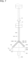
Fig. 7 is a diagram describing a method for identifying a jet from an angled jet lance according to an embodiment. -
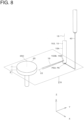
Fig. 8 is a diagram describing a method for identifying a jet from a lateral jet nozzle according to an embodiment. -
Fig. 9 is a cross-sectional view taken along plane IX inFig. 8 . -
Fig. 10 is a diagram describing a method for identifying a jet from a straight jet nozzle according to an embodiment. -
Fig. 11 is a diagram describing a method for identifying a jet from a fan jet nozzle according to an embodiment. - As shown in
Fig. 1 , aninspection apparatus 10 includes abody 11, a movingunit 14,nozzles 15, a cleaning table 17, apump 18, atouch probe 23, and acontroller 29. Thecontroller 29 includes areceiver 31. Theinspection apparatus 10 may also include aturret 13, adummy workpiece 21, atransmitter 27, and thereceiver 31. - The
inspection apparatus 10 is installed in acleaning device 20. Thecleaning device 20 includes thebody 11, theturret 13, the movingunit 14, thenozzles 15, the cleaning table 17, thepump 18, and thecontroller 29. Thecleaning device 20 uses ajet 19 produced from eachnozzle 15 hitting aworkpiece 12 to clean theworkpiece 12 or to deburr theworkpiece 12. Examples of thecleaning device 20 are described inU.S. Patent Nos. 9364869 9393627 9630217 cleaning device 20 may be one of the JCC Series (Sugino Machine Limited). - The cleaning table 17 is installed in the
body 11. The cleaning table 17 may be swingable about a rotation axis parallel to the X-axis. The cleaning table 17 receives theworkpiece 12 or thedummy workpiece 21 that is aligned and fixed at a predetermined position. - The
pump 18 is a liquid pump, such as a piston pump, a gear pump, or a volute pump. Thepump 18 applies a positive pressure to a cleaning liquid in a cleaning liquid tank (not shown), and feeds the cleaning liquid to thenozzle 15 through theturret 13. - The moving
unit 14 is installed in thebody 11. The movingunit 14 can freely move theturret 13 and thenozzles 15 relative to the cleaning table 17 in the lateral direction (X-direction), the front-rear direction (Y-direction), and the vertical direction (Z-direction). - The
turret 13 is attached to the movingunit 14. Theturret 13 has arotation axis 16 parallel to the Z-axis. Theturret 13 may includemultiple nozzles 15. Theturret 13 rotates to set onenozzle 15 in position. Theturret 13 feeds the cleaning liquid to the selectednozzle 15. - The
nozzles 15 are mounted on theturret 13. As shown inFig. 6 , for example, eachnozzle 15 includes ashaft 15A andejection orifices 15B. Eachnozzle 15 may be rotatable about therotation axis 16 or may be positioned in the rotation direction. Eachnozzle 15 may be, for example, a lance 151, an angled jet lance 152, a lateral jet nozzle 153, a straight jet nozzle 154, or a fan jet nozzle 155. Eachejection orifice 15B produces a high-pressure jet 19 along anaxis 22. - The
dummy workpiece 21 has a shape similar to theworkpiece 12 at least at the joint with the cleaning table 17. The cleaning table 17 receives, in place of theworkpiece 12, thedummy workpiece 21 fixed at a mount position for theworkpiece 12. Thedummy workpiece 21 includes atouch probe 23. Thetouch probe 23 includes astylus 25. Thestylus 25 is preferably disc-shaped. Thestylus 25 has anupper surface 25A, acylindrical surface 25B, and acenter line 25C. Theupper surface 25A is a top surface of thestylus 25. The dummy workpiece 21 includes thetransmitter 27. Thetouch probe 23 detects a contact on thestylus 25 upon receiving a force larger than or equal to a detection force. In response to this, thetransmitter 27 wirelessly transmits a contact signal to thereceiver 31. More specifically, thetransmitter 27 generates a contact signal in response to a force acting on thestylus 25. - The
touch probe 23 may be directly fixed to the cleaning table 17 without thedummy workpiece 21 between thetouch probe 23 and the cleaning table 17. Thetouch probe 23 may instead be fixed to an engagement member such as a pallet to be engageable or removable at a predetermined position on the cleaning table 17, which is different from the mount position of theworkpiece 12. - The
touch probe 23 may be prefixed at a predetermined position of thebody 11. In this case, thecleaning device 20 may also include a shutter or a cover (not shown) that covers thetouch probe 23 during cleaning of theworkpiece 12. - The
controller 29 may include a numerical controller. Thecontroller 29 numerically controls the movingunit 14 and the cleaning table 17. Thereceiver 31 receives contact signals. - The
transmitter 27 and thereceiver 31 may perform wired communication, instead of wireless communication. - Referring now to
Figs. 2 and3 , a method for inspecting thenozzles 15 for breakage will be described. An operator or a transporting device (not shown) mounts thetouch probe 23 on the cleaning table 17 (S1). Thecontroller 29 rotates thenozzles 15 about the rotation axis 16 (S2). Thecontroller 29 moves onenozzle 15 to a first position (hereafter, position P1) (S3). When thecontroller 29 receives a contact signal, the processing advances to step S10. Otherwise, the processing advances to step S6 (S4). Thecontroller 29 moves thenozzle 15 to a second position (hereafter, position P2) (S6). When thecontroller 29 receives a contact signal, the processing advances to step S8. Otherwise, the processing advances to step S10 (S7). Subsequently, thecontroller 29 moves thenozzle 15 to a third position (hereafter, position P3) (S8). When thecontroller 29 receives a contact signal, the processing advances to step S10. Otherwise, the processing advances to step S11 (S9). Thecontroller 29 moves thenozzle 15 to a fourth position (hereafter, position P4) (S11). When thecontroller 29 receives a contact signal, the processing advances to step S15. Otherwise, the processing advances to step S10 (S12). In step S10, thecontroller 29 determines that the shape of thenozzle 15 is inappropriate. The processing then advances to step S24. - Subsequently, the
controller 29 causes thenozzle 15 to produce the jet 19 (S15). Thecontroller 29 moves thenozzle 15 to a fifth position (hereafter, position P5) (S16). When thecontroller 29 receives a contact signal, the processing advances to step S22. Otherwise, the processing advances to step S19 (S17). Thecontroller 29 moves thenozzle 15 to a sixth position (hereafter, position P6) (S19). When thecontroller 29 receives a contact signal, the processing advances to step S23. Otherwise, the processing advances to step S22 (S20). In step S22, thecontroller 29 determines that the jet from thenozzle 15 is inappropriate. In step S23, thecontroller 29 determines that the jet from thenozzle 15 is appropriate. The processing then advances to step S24. - The controller stops rotating the nozzle 15 (S24). Finally, the operator or the transporting device removes the
touch probe 23 from the cleaning table 17 (S25). - Steps S1 to S12 and steps S24 to S25 may be eliminated.
- A method for identifying the shape of the nozzle 15 (steps S3 to S12) will now be described in detail using the lance 151 as an example. The same method can be used for the angled jet lance 152, the lateral jet nozzle 153, the straight jet nozzle 154, and the fan jet nozzle 155. Positions P1 to P6 and
paths 35 to 43 (described below) are defined assuming that the shape of thenozzle 15 and its jet shape and direction are as designed (normal). - Steps S3 to S7 will be described with reference to
Fig. 4 . The lance 151 includes theshaft 15A, which extends along therotation axis 16, andmultiple ejection orifices 151B located in the direction perpendicular to therotation axis 16 on the distal end of theshaft 15A. At the position P1, theshaft 15A is on acenter line 25C at a distance ΔZ3 upward from theupper surface 25A (+Z-direction) of thestylus 25. At the position P2, theshaft 15A is on thecenter line 25C at a distance ΔZ1 from theupper surface 25A toward the basal end of the stylus 25 (-Z-direction). The distance ΔZ1 is the upper limit of the allowable range from a reference length of the lance 151. The distance ΔZ3 is the lower limit of the allowable range from a reference length of the lance 151. The distances ΔZ1 and ΔZ3 are determined based on the finished dimensional accuracy, assembly accuracy, and positioning accuracy of the lance 151. More specifically, the distances ΔZ1 and ΔZ3 are normal distances (second normal distances) calculated from the normal nozzle shape. - In step S3, the
controller 29 moves the lance 151 along thepath 35, on which the lance 151 does not contact thestylus 25, and moves the lance 151 to the position P1. Preferably, thepath 35 extends along thecenter line 25C near its terminal end. Positioning hereafter refers to fast forwarding. The positioning may include linear movement. - Step S4 may be performed in parallel with step S3.
- In step S6, the
controller 29 linearly moves the lance 151 to the position P2 at a constant speed. The speed may specifically be 50 to 200 mm per minute (inclusive). - Step S7 may be performed in parallel with step S6.
- Steps S8 to S12 will be described with reference to
Fig. 5 . At the position P3, theshaft 15A is at a distance ΔX3 from thecylindrical surface 25B. The position P4 is at the same level as the position P3. At the position P4, theshaft 15A is located at a distance ΔX1 inward from thecylindrical surface 25B. The positions P3 and P4 may be determined to allow the distal end of the lance 151 to contact a middle portion of thecylindrical surface 25B at height H. The distance ΔX3 corresponds to the sum of the allowable deflection and the maximum tolerance from a reference radius of theshaft 15A. The distance ΔX1 corresponds to a minimum tolerance from the reference radius of theshaft 15A. The distances ΔX1 and ΔX3 are normal distances (second normal distances) calculated from the normal nozzle shape. - In step S8, the
controller 29 moves the lance 151 along apath 37, on which the lance 151 does not contact thestylus 25, and moves the lance 151 to the position P3. Preferably, thepath 37 is redirected in X-direction near its terminal end. - Step S9 may be performed in parallel with step S8.
- In step S11, the
controller 29 linearly moves the lance 151 to the position P4 at a constant speed. Preferably, the speed is 50 to 200 mm per minute (inclusive). - Step S12 may be performed in parallel with step S11.
- In step S10, the
controller 29 determines that the shape of the lance 151 is inappropriate. Thecontroller 29 determines that the lance 151 has breakage. - In steps S3 to S7, the distal end of the lance 151 is moved toward the
upper surface 25A of thestylus 25. When the lance 151 contacts thestylus 25 in a normal range for the first time, thecontroller 29 determines that the length of the lance 151 is normal. - In steps S8 to S12, the side surface of the lance 151 is radially moved toward the
cylindrical surface 25B of thestylus 25. When the lance 151 contacts thestylus 25 in a normal range for the first time, thecontroller 29 determines that the total runout of the lance 151 is normal. - In steps S8 to S12, the lance 151 is moved in X-direction toward the
stylus 25. The lance 151 may be moved in Y-direction, instead of X-direction. - Step S2 may not be performed after step S1, but may be performed immediately before step S8. Further, steps S3 to S7 and steps S8 to S12 may be exchanged.
- When step S2 is eliminated, steps S8 to S12 may be repeatedly performed with the lance 151 being moved toward the
stylus 25 in Y-direction. - A method for inspecting an ejection direction (steps S15 to S23) will now be described in detail. Unless otherwise specified, the inspection method is performed with the same procedure independently of the types of the
nozzles 15. However, the positions P5 and P6 may vary depending on the type of thenozzles 15. The method for inspecting the lance 151 will now be described below with reference toFig. 6 . - A position P51 (fifth position) is determined to have the
rotation axis 16 at a distance L1 from thecylindrical surface 25B (+X-direction in the figure) and theaxis 22 at a distance ΔZ5 upward from theupper surface 25A of the stylus 25 (+Z-direction in the figure). The distance L1 is determined based on the distance from the lance 151 to a wall surface of a hole extending through theworkpiece 12, during cleaning. The distance ΔZ5 is determined as a tolerance of the hitting position of the jet corresponding to the distance L1. - The distance ΔZ5 may be determined based on the diameter of each
ejection orifice 151B and the distance L2. The distance L2 herein is the sum of the outer diameter of thestylus 25 and the distance L1. The distances L1 and ΔZ5 can be appropriately determined in accordance with the impulsive force of thejet 19 on thestylus 25. - The position P61 (sixth position) is on the extension of the
rotation axis 16 extending from the position P51, and is determined to have theaxis 22 at a distance ΔZ7 from theupper surface 25A toward the basal end of the stylus 25 (-Z-direction in the figure). The distance ΔZ7 is determined based on the range in which thejet 19 hits in the height direction (-Z-direction in the figure) at the distance L1. The position P61 is the positon of thejet 19 nearest the basal end of thestylus 25 detectable by thestylus 25.
The distances ΔZ5 and ΔZ7 are normal distances (first normal distances) calculated from the normal jet shape. - In step S15, the
pump 18 feeds the cleaning liquid to thenozzle 15. Thus, thenozzle 15 produces thejet 19. Thejet 19 has a stabilized shape when the pressure inside thenozzle 15 increases sufficiently. After thejet 19 is stabilized, step S16 is performed. - In step S16, the
controller 29 moves the lance 151 to the position P51. The lance 151 herein moves along apath 39 on which thejet 19 does not contact thestylus 25. Preferably, thepath 39 extends parallel to thecenter line 25C near its terminal end. - Step S17 may be performed in parallel with step S16.
- In step S19, the
controller 29 linearly moves the lance 151 to a position P61 at a constant speed. Preferably, the speed is 50 to 200 mm per minute (inclusive). - Step S20 may be performed in parallel with step S19.
- In step S22, the
controller 29 determines that thejet 19 is inappropriate. In other words, thecontroller 29 determines that thejet 19 is abnormal due to clogging or wear of the ejection orifices 15B. - A method for inspecting the
jet 19 from the angled jet lance 152 will now be described with reference toFig. 7 . The angled jet lance 152 includesmultiple ejection orifices 152B at the distal end of theshaft 15A at an angle with respect to therotation axis 16. - A position P52 (fifth position) is determined to have the
center line 25C and therotation axis 16 coaxially aligned, eachaxis 22 not crossing thestylus 25, and theaxis 22 and anedge 25D of theupper surface 25A at a distance Δ1 between them. A position P62 (sixth position) is determined to have thecenter line 25C and therotation axis 16 coaxially aligned, theaxis 22 crossing thestylus 25, and theaxis 22 and theedge 25D at a distance Δ3 between them. The distances Δ1 and Δ3 are determined in accordance with the allowable inclination of eachjet 19 and the diameter of the ejection orifices 152B. More specifically, the distances Δ1 and Δ3 are normal distances (first normal distances) calculated from the normal jet shape. - In step S16, the angled jet lance 152 moves along a
path 41. Thepath 41 extends along thecenter line 25C at least within the range in which thejet 19 approaches thestylus 25. - A method for inspecting the jet from the lateral jet nozzle 153 will now be described with reference to
Figs. 8 and9 . The lateral jet nozzle 153 includes oneejection orifice 153B located in the direction perpendicular to therotation axis 16 on the distal end of theshaft 15A. Before step S15 for inspecting the lateral jet nozzle 153, the lateral jet nozzle 153 is positioned about therotation axis 16 to have theaxis 22 extending in a predetermined direction (-Y-direction in the figure). - The position P53 (fifth position) and the position P63 (sixth position) are determined at around a middle in the height H of the
stylus 25. A plane including the positions P53 and P63 and perpendicular to therotation axis 16 is referred to as a plane IX. - At the position P53, the
axis 22 is at a distance ΔX5 from the tangent of thecylindrical surface 25B, and at a distance L3 from thecenter line 25C in the tangential direction (+Y-direction in the figure). The distance ΔX5 is a maximum tolerance at which thejet 19 does not contact thestylus 25. At the position P63, theaxis 22 is positioned in the same rotation direction as at the position P53, and theaxis 22 is at the distance L3 in the tangential direction, and at a distance ΔX7 radially inward from the tangent of thecylindrical surface 25B. The distances ΔX5 and ΔX7 are determined based on the positioning accuracy of the lateral jet nozzle 153, the diameter of theejection orifice 153B, the divergence of thejet 19, and the distance L3. More specifically, the distances ΔX5 and ΔX7 are normal distances (first normal distances) calculated from the normal jet shape. - In step S16, the
jet 19 passes along thepath 43 on which thejet 19 does not contact thestylus 25. Preferably, thepath 43 extends in the radial direction of thestylus 25 and in the direction perpendicular to the axis 22 (X-direction in the figure) near its terminal end. - A method for inspecting the jet from the straight jet nozzle 154 will now be described with reference to
Fig. 10 . The straight jet nozzle 154 includes anejection orifice 154B, which ejects alinear jet 19 along therotation axis 16, at the distal end of theshaft 15A. While rotating, the straight jet nozzle 154 gradually moves thejet 19 toward thestylus 25 along thecylindrical surface 25B (refer toFig. 10 ) or along theupper surface 25A. This allows identification of the jet inclination. - A method for inspecting the jet from the fan jet nozzle 155 will now be described with reference to
Fig. 11 . The fan jet nozzle 155 includes anejection orifice 155B at the distal end of theshaft 15A, through which thejet 19 is ejected to spread in a fan shape on a plane 155C including therotation axis 16. Before step S15 for inspecting the jet from the fan jet nozzle 155, the fan jet nozzle 155 is positioned in the rotation direction to determine the direction in which thejet 19 spreads (X-direction inFig. 11 ). Thejet 19 moves toward thestylus 25 in the direction perpendicular to the plane 155C (Y-direction inFig. 11 ). - The positions P1, P3, and P5 correspond to search start positions. The positions P2, P4, and P6 correspond to search end positions.
- Steps S1 to S24 may be performed for each of
multiple nozzles 15 mounted on theturret 13. - The
cleaning device 20 implements the inspection method according to the present embodiment using thedummy workpiece 21 mounted on the cleaning table 17 instead of theworkpiece 12 at constant frequencies. Thecleaning device 20 may implement the inspection method according to the present embodiment every after cleaning a predetermined number of (e.g., 100)workpieces 12, every after a predetermined period (e.g., ten hours) passes, or regularly (e.g., every business day). - A transporting device may instruct the
cleaning device 20 to implement the method for inspecting thenozzle 15 for any breakage after thedummy workpiece 21 is mounted on the cleaning table 17. In response to the instruction, thecleaning device 20 implements the inspection method according to the present embodiment. - The inspection method according to the present embodiment enables inspection of the shape and the ejection state of the
nozzle 15 inside thecleaning device 20 using thetouch probe 23. Inspecting thenozzle 15 with appropriate frequencies ensures that thecleaning device 20 is in the normal state. - The
inspection apparatus 10 includes thetouch probe 23 mounted on thedummy workpiece 21 and thus accurately mounted on the cleaning table 17. In addition, thetouch probe 23 on thedummy workpiece 21 can be mounted onto thebody 11 for use only at inspection. Thecleaning device 20 ejects a high-pressure jet 19 in every direction. Thejet 19 hitting theworkpiece 12 bounces. The jet hitting theworkpiece 12 contains burrs, chips, and other foreign matter adhering to theworkpiece 12. Removing thetouch probe 23 from thebody 11 prevents the jet or such foreign matter from undesirably hitting thetouch probe 23, and thus can extend the life of thetouch probe 23. Thetouch probe 23 is mounted only at inspection. This structure provides a wider space for cleaning. With thetransmitter 27 and thereceiver 31 communicating wirelessly, thedummy workpiece 21 can be handled easily. - The embodiments disclosed herein should not be construed to be restrictive, but may be modified variously to cover all technical matters falling within the technical ideas defined by the appended claims. Although preferred exemplary embodiments have been shown and described, it will be apparent to those skilled in the art that various changes, modifications, alterations, or improvements may be made to the invention in view of the disclosure herein, and all such variations are considered within the scope of the invention, since the full scope of protection of the present invention is only defined by the appended claims.
-
- 10 inspection apparatus
- 14 moving unit
- 15 nozzle
- 17 cleaning table
- 19 jet
- 21 dummy workpiece
- 23 touch probe
- 25 stylus
- 27 transmitter
- 29 controller
- 31 receiver
Claims (8)
- A method for inspecting a nozzle (15) inside a cleaning device (20) for cleaning or deburring a workpiece (12) by using a jet (19) produced from a nozzle (15) to hit the workpiece (12),
whereby the cleaning device (20) comprises:the nozzle (15) configured to produce the jet (19);a cleaning table (17);a moving unit (14) configured to move the nozzle (15) relative to the cleaning table (17);the method comprising the steps of:producing the jet (19) from the nozzle (15);moving the nozzle (15) to cause the jet (19) to approach a stylus (25) of a touch probe (23);generating a contact signal under a force acting on the stylus (25); anddetermining that the jet (19) is appropriate in response to a contact signal received first after an axis of the jet (19) is positioned at a distance from the stylus (25) that is equal to or less than a first normal distance calculated from a normal jet shape by assuming that the shape of the nozzle (15) and its jet shape and its direction are as designed. - The nozzle inspection method according to claim 1, further comprising:moving the nozzle (15) to a search start position at which the axis of the jet (19) is positioned at the first normal distance from a surface (25A, 25B) of the stylus (25);moving the nozzle (15) from the search start position to a search end position at which the axis of the jet (19) is positioned at the first normal distance toward a center of the stylus (25) from the surface (25A, 25B) of the stylus (25); anddetermining that the jet (19) is appropriate in response to no contact signal received when moving the nozzle (15) to the search start position and a contact signal received when moving the nozzle (15) from the search start position to the search end position.
- The nozzle inspection method according to claim 1 or claim 2, further comprising:
moving the nozzle (15) perpendicularly to the axis of the jet (19). - The nozzle inspection method according to any one of claims 1 to 3, further comprising:
rotating the nozzle (15). - The nozzle inspection method according to any one of claims 1 to 4, further comprising:moving the nozzle (15) toward the stylus (25); anddetermining that a shape of the nozzle (15) is appropriate in response to a contact signal received first after the nozzle (15) is at a distance from the stylus (25) that is equal to or less than a second normal distance calculated from a normal nozzle shape.
- The nozzle inspection method according to claim 5, further comprising:moving the nozzle (15) from above the stylus (25) having a cylindrical shape to an upper surface (25A) of the stylus (25); andmoving the nozzle (15) in a radial direction of the stylus (25) to a cylindrical surface (25B) of the stylus (25).
- The nozzle inspection method according to any one of claims 1 to 6, further comprising:mounting a dummy workpiece (21) to which the touch probe (23) is fixed onto a mount table (17) of the cleaning device (20); andremoving the dummy workpiece (21) from the mount table (17) after inspection of the jet (19) or the shape of the nozzle (15).
- A cleaning device (20) for cleaning or deburring a workpiece (12) by using a jet (19) produced from a nozzle (15) to hit the workpiece (12) with a nozzle inspection apparatus (10) installed in the cleaning device (20), comprising:the nozzle (15) configured to produce the jet (19);a cleaning table (17);a moving unit (14) configured to move the nozzle (15) relative to the cleaning table (17);a dummy workpiece (21) mountable on the cleaning table (17) at an inspection position;a touch probe (23) mounted on the dummy workpiece (21), the touch probe (23) includinga stylus (25), anda wireless transmitter (27) configured to generate a contact signal under a force acting on the stylus (25); anda controller (29) including a receiver (31) configured to receive the contact signal;the controller (29) configured to determine that the jet (19) is appropriate in response to a contact signal received first after an axis of the jet (19) is positioned at a distance from the stylus (25) that is equal to or less than a first normal distance calculated from a normal jet shape by assuming that the shape of the nozzle (15) and its jet shape and its direction are as designed.
Applications Claiming Priority (1)
| Application Number | Priority Date | Filing Date | Title |
|---|---|---|---|
| US201762599212P | 2017-12-15 | 2017-12-15 |
Publications (2)
| Publication Number | Publication Date |
|---|---|
| EP3499176A1 EP3499176A1 (en) | 2019-06-19 |
| EP3499176B1 true EP3499176B1 (en) | 2023-11-01 |
Family
ID=63517686
Family Applications (1)
| Application Number | Title | Priority Date | Filing Date |
|---|---|---|---|
| EP18192568.6A Active EP3499176B1 (en) | 2017-12-15 | 2018-09-04 | Nozzle inspection method and apparatus |
Country Status (5)
| Country | Link |
|---|---|
| US (1) | US10890427B2 (en) |
| EP (1) | EP3499176B1 (en) |
| JP (2) | JP6665243B2 (en) |
| KR (1) | KR102176859B1 (en) |
| CN (1) | CN109926377B (en) |
Families Citing this family (4)
| Publication number | Priority date | Publication date | Assignee | Title |
|---|---|---|---|---|
| EP3456953B1 (en) * | 2017-09-13 | 2021-07-14 | Vitesco Technologies GmbH | Apparatus and method for testing a fuel injector nozzle |
| JP6853165B2 (en) * | 2017-11-29 | 2021-03-31 | 株式会社スギノマシン | Jet device |
| JP6487084B1 (en) * | 2018-03-07 | 2019-03-20 | 株式会社スギノマシン | Nozzle inspection apparatus and nozzle inspection method |
| CN114654220B (en) * | 2022-02-28 | 2023-09-15 | 东方电气集团东方电机有限公司 | Impact model water turbine nozzle assembling and aligning method |
Family Cites Families (23)
| Publication number | Priority date | Publication date | Assignee | Title |
|---|---|---|---|---|
| US3449948A (en) * | 1967-06-13 | 1969-06-17 | Parker Hannifin Corp | Nozzle spray test device |
| DE3586581T2 (en) * | 1984-11-27 | 1993-04-15 | Topcon Corp | CONTACTLESS TONOMETER. |
| JP2547040Y2 (en) | 1991-12-26 | 1997-09-03 | 三菱電線工業株式会社 | Contact probe device |
| US5461797A (en) * | 1994-04-19 | 1995-10-31 | M&M Precision Systems Corporation | Object measuring system |
| DE19517775C2 (en) | 1994-05-16 | 2000-09-28 | Sven M Stoerner | Measuring device and method for determining the cleaning power of cleaning devices provided for pipe and sewer cleaning and generating a fluid jet |
| JPH09303236A (en) | 1996-05-17 | 1997-11-25 | Toyota Motor Corp | Inspecting method for fuel injection system |
| US6508112B1 (en) * | 2000-01-21 | 2003-01-21 | Dean Verhoeven | Tomographic spray momentum mapping system |
| JP3687896B2 (en) * | 2000-09-27 | 2005-08-24 | 富士重工業株式会社 | Measuring device for pulley for continuously variable transmission |
| GB0126232D0 (en) * | 2001-11-01 | 2002-01-02 | Renishaw Plc | Calibration of an analogue probe |
| DE10331206A1 (en) * | 2003-07-10 | 2005-01-27 | Daimlerchrysler Ag | Spray material is applied to a workpiece by directing a spray jet of an applicator, monitoring the jet geometry, and comparing it with a predetermined geometry |
| JP4086766B2 (en) * | 2003-11-28 | 2008-05-14 | キヤノン株式会社 | Process cartridge and process cartridge assembling method |
| JP4331760B2 (en) * | 2007-01-22 | 2009-09-16 | シャープ株式会社 | Droplet discharge head inspection device and droplet discharge device |
| DE102007029787B3 (en) * | 2007-06-27 | 2008-09-11 | Trumpf Werkzeugmaschinen Gmbh + Co. Kg | Method for determining a point of contact of a laser beam at an edge of a body and laser processing machine |
| GB0713678D0 (en) | 2007-07-13 | 2007-08-22 | Delphi Tech Inc | Apparatus and methods for testing a fuel injector nozzle |
| JP4653824B2 (en) * | 2008-07-29 | 2011-03-16 | ファナック株式会社 | A machine tool system that measures the shape of a measurement object using an on-machine measuring device |
| FR2948602B1 (en) * | 2009-07-30 | 2011-08-26 | Markem Imaje | DEVICE FOR DETECTING DIRECTIVITY OF LIQUID JET DROPPER PATHWAYS, ELECTROSTATIC SENSOR, PRINT HEAD, AND ASSOCIATED CONTINUOUS INK JET PRINTER |
| JP5704997B2 (en) | 2010-09-10 | 2015-04-22 | 株式会社スギノマシン | Turret cleaning device |
| DE102011008002B4 (en) | 2011-01-04 | 2014-01-16 | Jürgen Richter | Jet measuring device |
| CN102506732A (en) * | 2011-10-28 | 2012-06-20 | 江苏豪然喷射成形合金有限公司 | Online detection system and detection method for cylindrical ingots in spray forming |
| WO2014189541A1 (en) * | 2013-05-21 | 2014-11-27 | Aquionics, Inc. | Fluid diagnostic devices and methods of using the same |
| JP6147623B2 (en) | 2013-09-17 | 2017-06-14 | 株式会社スギノマシン | Turret device |
| SE537884C2 (en) * | 2014-01-20 | 2015-11-10 | Nip Control Ab | Calibration unit for roll pin gauge |
| JP6227496B2 (en) | 2014-07-24 | 2017-11-08 | 株式会社スギノマシン | Cleaning device |
-
2018
- 2018-08-06 JP JP2018147984A patent/JP6665243B2/en active Active
- 2018-08-29 US US16/116,835 patent/US10890427B2/en active Active
- 2018-09-04 EP EP18192568.6A patent/EP3499176B1/en active Active
- 2018-09-06 KR KR1020180106269A patent/KR102176859B1/en active IP Right Grant
- 2018-09-12 CN CN201811064333.5A patent/CN109926377B/en active Active
-
2020
- 2020-02-19 JP JP2020026182A patent/JP6974521B2/en active Active
Also Published As
| Publication number | Publication date |
|---|---|
| JP6974521B2 (en) | 2021-12-01 |
| US20190187173A1 (en) | 2019-06-20 |
| JP2020097036A (en) | 2020-06-25 |
| JP2019107641A (en) | 2019-07-04 |
| CN109926377B (en) | 2021-08-31 |
| US10890427B2 (en) | 2021-01-12 |
| CN109926377A (en) | 2019-06-25 |
| KR102176859B1 (en) | 2020-11-10 |
| KR20190072401A (en) | 2019-06-25 |
| EP3499176A1 (en) | 2019-06-19 |
| JP6665243B2 (en) | 2020-03-13 |
Similar Documents
| Publication | Publication Date | Title |
|---|---|---|
| EP3499176B1 (en) | Nozzle inspection method and apparatus | |
| EP2707176B1 (en) | Drilling machine having hole measurement capability | |
| CN103962891B (en) | Machining unit for CNC machine tool | |
| CN101669009B (en) | Apparatus and method for surface measurement | |
| EP2920549B1 (en) | Method and apparatus for measuring a workpiece with a machine tool | |
| EP2839241B1 (en) | Method of finding a feature of an object using a machine tool and corresponding machine tool apparatus | |
| JP5039666B2 (en) | Surface roughness measuring method, surface roughness measuring apparatus and processing apparatus | |
| CN107883964B (en) | Device for detecting motion trail of single point on workpiece ring in ring polishing processing and method for detecting motion trail by using device | |
| CN107966388B (en) | Follow-up type single-layer grinding wheel abrasive particle distribution characteristic detection method and device | |
| CN102528299B (en) | Method for checking gas nozzle arranged in laser processing machine and attached laser processing machine | |
| JP6801290B2 (en) | Method of positioning the operator with respect to the target object and nozzle device | |
| US20150220077A1 (en) | Method and device for measuring a tool received in a workpiece processing machine | |
| US20200114442A1 (en) | Method and apparatus for monitoring a bar blade chucking and/or a blade slot of a bar blade cutter head for bevel gear production | |
| JP7068567B2 (en) | Optimal hole diameter measuring method and optimum hole diameter measuring device | |
| JPH10339623A (en) | Method and device for measuring hole size and position | |
| CN104006775B (en) | The measuring method of aperture position degree | |
| CN109175122A (en) | Transfer processing method and system | |
| CN210293159U (en) | Workpiece length detection device | |
| EP0729008A1 (en) | Application and method for detecting changes in distance | |
| CN216631805U (en) | Shower nozzle calibration instrument | |
| KR20190066347A (en) | Multiple spindle drilling system | |
| CN218628237U (en) | Pipe body inner diameter detection device | |
| JPH0714882Y2 (en) | Ultrasonic inspection device | |
| KR101392656B1 (en) | Tool clamping certifying apparatus and method for certiying tool clamping thereof | |
| CN117491478A (en) | Array vortex detection method and device for edge cracks of non-planar multi-size process hole |
Legal Events
| Date | Code | Title | Description |
|---|---|---|---|
| PUAI | Public reference made under article 153(3) epc to a published international application that has entered the european phase |
Free format text: ORIGINAL CODE: 0009012 |
|
| STAA | Information on the status of an ep patent application or granted ep patent |
Free format text: STATUS: REQUEST FOR EXAMINATION WAS MADE |
|
| 17P | Request for examination filed |
Effective date: 20180904 |
|
| AK | Designated contracting states |
Kind code of ref document: A1 Designated state(s): AL AT BE BG CH CY CZ DE DK EE ES FI FR GB GR HR HU IE IS IT LI LT LU LV MC MK MT NL NO PL PT RO RS SE SI SK SM TR |
|
| AX | Request for extension of the european patent |
Extension state: BA ME |
|
| STAA | Information on the status of an ep patent application or granted ep patent |
Free format text: STATUS: EXAMINATION IS IN PROGRESS |
|
| 17Q | First examination report despatched |
Effective date: 20210507 |
|
| STAA | Information on the status of an ep patent application or granted ep patent |
Free format text: STATUS: EXAMINATION IS IN PROGRESS |
|
| RAP3 | Party data changed (applicant data changed or rights of an application transferred) |
Owner name: SUGINO MACHINE LIMITED |
|
| GRAP | Despatch of communication of intention to grant a patent |
Free format text: ORIGINAL CODE: EPIDOSNIGR1 |
|
| STAA | Information on the status of an ep patent application or granted ep patent |
Free format text: STATUS: GRANT OF PATENT IS INTENDED |
|
| RIC1 | Information provided on ipc code assigned before grant |
Ipc: B08B 5/02 20060101ALN20230414BHEP Ipc: B08B 3/02 20060101ALN20230414BHEP Ipc: B05B 15/00 20180101ALN20230414BHEP Ipc: G01B 5/20 20060101ALN20230414BHEP Ipc: G01B 5/008 20060101AFI20230414BHEP |
|
| INTG | Intention to grant announced |
Effective date: 20230504 |
|
| GRAS | Grant fee paid |
Free format text: ORIGINAL CODE: EPIDOSNIGR3 |
|
| GRAA | (expected) grant |
Free format text: ORIGINAL CODE: 0009210 |
|
| STAA | Information on the status of an ep patent application or granted ep patent |
Free format text: STATUS: THE PATENT HAS BEEN GRANTED |
|
| AK | Designated contracting states |
Kind code of ref document: B1 Designated state(s): AL AT BE BG CH CY CZ DE DK EE ES FI FR GB GR HR HU IE IS IT LI LT LU LV MC MK MT NL NO PL PT RO RS SE SI SK SM TR |
|
| REG | Reference to a national code |
Ref country code: GB Ref legal event code: FG4D |
|
| REG | Reference to a national code |
Ref country code: CH Ref legal event code: EP |
|
| REG | Reference to a national code |
Ref country code: IE Ref legal event code: FG4D |
|
| REG | Reference to a national code |
Ref country code: DE Ref legal event code: R096 Ref document number: 602018060285 Country of ref document: DE |
|
| REG | Reference to a national code |
Ref country code: LT Ref legal event code: MG9D |
|
| REG | Reference to a national code |
Ref country code: NL Ref legal event code: MP Effective date: 20231101 |
|
| PG25 | Lapsed in a contracting state [announced via postgrant information from national office to epo] |
Ref country code: GR Free format text: LAPSE BECAUSE OF FAILURE TO SUBMIT A TRANSLATION OF THE DESCRIPTION OR TO PAY THE FEE WITHIN THE PRESCRIBED TIME-LIMIT Effective date: 20240202 |
|
| PG25 | Lapsed in a contracting state [announced via postgrant information from national office to epo] |
Ref country code: IS Free format text: LAPSE BECAUSE OF FAILURE TO SUBMIT A TRANSLATION OF THE DESCRIPTION OR TO PAY THE FEE WITHIN THE PRESCRIBED TIME-LIMIT Effective date: 20240301 |
|
| PG25 | Lapsed in a contracting state [announced via postgrant information from national office to epo] |
Ref country code: LT Free format text: LAPSE BECAUSE OF FAILURE TO SUBMIT A TRANSLATION OF THE DESCRIPTION OR TO PAY THE FEE WITHIN THE PRESCRIBED TIME-LIMIT Effective date: 20231101 |
|
| REG | Reference to a national code |
Ref country code: AT Ref legal event code: MK05 Ref document number: 1627663 Country of ref document: AT Kind code of ref document: T Effective date: 20231101 |
|
| PG25 | Lapsed in a contracting state [announced via postgrant information from national office to epo] |
Ref country code: NL Free format text: LAPSE BECAUSE OF FAILURE TO SUBMIT A TRANSLATION OF THE DESCRIPTION OR TO PAY THE FEE WITHIN THE PRESCRIBED TIME-LIMIT Effective date: 20231101 |