EP3499028B1 - Gestell zum transport eines triebstrangs einer windturbine - Google Patents
Gestell zum transport eines triebstrangs einer windturbine Download PDFInfo
- Publication number
- EP3499028B1 EP3499028B1 EP18382813.6A EP18382813A EP3499028B1 EP 3499028 B1 EP3499028 B1 EP 3499028B1 EP 18382813 A EP18382813 A EP 18382813A EP 3499028 B1 EP3499028 B1 EP 3499028B1
- Authority
- EP
- European Patent Office
- Prior art keywords
- support
- tool according
- arm
- tool
- power train
- Prior art date
- Legal status (The legal status is an assumption and is not a legal conclusion. Google has not performed a legal analysis and makes no representation as to the accuracy of the status listed.)
- Active
Links
Images



Classifications
-
- F—MECHANICAL ENGINEERING; LIGHTING; HEATING; WEAPONS; BLASTING
- F03—MACHINES OR ENGINES FOR LIQUIDS; WIND, SPRING, OR WEIGHT MOTORS; PRODUCING MECHANICAL POWER OR A REACTIVE PROPULSIVE THRUST, NOT OTHERWISE PROVIDED FOR
- F03D—WIND MOTORS
- F03D13/00—Assembly, mounting or commissioning of wind motors; Arrangements specially adapted for transporting wind motor components
- F03D13/40—Arrangements or methods specially adapted for transporting wind motor components
-
- F—MECHANICAL ENGINEERING; LIGHTING; HEATING; WEAPONS; BLASTING
- F16—ENGINEERING ELEMENTS AND UNITS; GENERAL MEASURES FOR PRODUCING AND MAINTAINING EFFECTIVE FUNCTIONING OF MACHINES OR INSTALLATIONS; THERMAL INSULATION IN GENERAL
- F16M—FRAMES, CASINGS OR BEDS OF ENGINES, MACHINES OR APPARATUS, NOT SPECIFIC TO ENGINES, MACHINES OR APPARATUS PROVIDED FOR ELSEWHERE; STANDS; SUPPORTS
- F16M11/00—Stands or trestles as supports for apparatus or articles placed thereon ; Stands for scientific apparatus such as gravitational force meters
- F16M11/20—Undercarriages with or without wheels
- F16M11/22—Undercarriages with or without wheels with approximately constant height, e.g. with constant length of column or of legs
-
- F—MECHANICAL ENGINEERING; LIGHTING; HEATING; WEAPONS; BLASTING
- F01—MACHINES OR ENGINES IN GENERAL; ENGINE PLANTS IN GENERAL; STEAM ENGINES
- F01D—NON-POSITIVE DISPLACEMENT MACHINES OR ENGINES, e.g. STEAM TURBINES
- F01D25/00—Component parts, details, or accessories, not provided for in, or of interest apart from, other groups
- F01D25/28—Supporting or mounting arrangements, e.g. for turbine casing
-
- F—MECHANICAL ENGINEERING; LIGHTING; HEATING; WEAPONS; BLASTING
- F05—INDEXING SCHEMES RELATING TO ENGINES OR PUMPS IN VARIOUS SUBCLASSES OF CLASSES F01-F04
- F05B—INDEXING SCHEME RELATING TO WIND, SPRING, WEIGHT, INERTIA OR LIKE MOTORS, TO MACHINES OR ENGINES FOR LIQUIDS COVERED BY SUBCLASSES F03B, F03D AND F03G
- F05B2240/00—Components
- F05B2240/50—Bearings
-
- F—MECHANICAL ENGINEERING; LIGHTING; HEATING; WEAPONS; BLASTING
- F05—INDEXING SCHEMES RELATING TO ENGINES OR PUMPS IN VARIOUS SUBCLASSES OF CLASSES F01-F04
- F05B—INDEXING SCHEME RELATING TO WIND, SPRING, WEIGHT, INERTIA OR LIKE MOTORS, TO MACHINES OR ENGINES FOR LIQUIDS COVERED BY SUBCLASSES F03B, F03D AND F03G
- F05B2240/00—Components
- F05B2240/60—Shafts
-
- F—MECHANICAL ENGINEERING; LIGHTING; HEATING; WEAPONS; BLASTING
- F05—INDEXING SCHEMES RELATING TO ENGINES OR PUMPS IN VARIOUS SUBCLASSES OF CLASSES F01-F04
- F05B—INDEXING SCHEME RELATING TO WIND, SPRING, WEIGHT, INERTIA OR LIKE MOTORS, TO MACHINES OR ENGINES FOR LIQUIDS COVERED BY SUBCLASSES F03B, F03D AND F03G
- F05B2260/00—Function
- F05B2260/02—Transport, e.g. specific adaptations or devices for conveyance
-
- F—MECHANICAL ENGINEERING; LIGHTING; HEATING; WEAPONS; BLASTING
- F16—ENGINEERING ELEMENTS AND UNITS; GENERAL MEASURES FOR PRODUCING AND MAINTAINING EFFECTIVE FUNCTIONING OF MACHINES OR INSTALLATIONS; THERMAL INSULATION IN GENERAL
- F16M—FRAMES, CASINGS OR BEDS OF ENGINES, MACHINES OR APPARATUS, NOT SPECIFIC TO ENGINES, MACHINES OR APPARATUS PROVIDED FOR ELSEWHERE; STANDS; SUPPORTS
- F16M7/00—Details of attaching or adjusting engine beds, frames, or supporting-legs on foundation or base; Attaching non-moving engine parts, e.g. cylinder blocks
-
- Y—GENERAL TAGGING OF NEW TECHNOLOGICAL DEVELOPMENTS; GENERAL TAGGING OF CROSS-SECTIONAL TECHNOLOGIES SPANNING OVER SEVERAL SECTIONS OF THE IPC; TECHNICAL SUBJECTS COVERED BY FORMER USPC CROSS-REFERENCE ART COLLECTIONS [XRACs] AND DIGESTS
- Y02—TECHNOLOGIES OR APPLICATIONS FOR MITIGATION OR ADAPTATION AGAINST CLIMATE CHANGE
- Y02E—REDUCTION OF GREENHOUSE GAS [GHG] EMISSIONS, RELATED TO ENERGY GENERATION, TRANSMISSION OR DISTRIBUTION
- Y02E10/00—Energy generation through renewable energy sources
- Y02E10/70—Wind energy
- Y02E10/72—Wind turbines with rotation axis in wind direction
Definitions
- the present invention can be included in the transport sector. Likewise, the present invention can be included in the field of renewable energy, in particular wind energy. More specifically, the object of the invention relates to a tool that is especially designed for transporting a windturbine power train subset, in particular for transporting what is called the low-speed shaft, along with the low-speed shaft bearings and the bearing supports.
- the power train is an assembly of the heaviest subsystem of the nacelle of a wind turbine, given that it includes the following elements: the low-speed shaft (LSS), low-speed shaft bearings (not shown), bearing supports and in certain cases a gearbox is included.
- LSS low-speed shaft
- bearings not shown
- gearbox in certain cases a gearbox is included.
- Figure 1 representing the state of the art, shows the low-speed shaft (1), which is a monolithic rotating piece in the form of a trumpet, and which has sections with decreasing cross sections and sections with uniform cross sections that are generally, but not necessarily, alternating.
- Low-speed bearings (not shown) are respectively mounted on two of said cross sections of different dimensions, which comprise a first bearing and a second bearing, the first bearing being supported on a cross section closer to a first end, with a greater cross section, of the low-speed shaft (1).
- each bearing is supported on the low-speed shaft (1) by a corresponding support (2, 3), in other words, by a first support (2) and a second support (3), respectively, wherein each support (2, 3), when mounted on the low-speed shaft (1), has a longitudinal direction that is perpendicular to the axis of revolution of the low-speed shaft (1).
- the two supports (2, 3) have the same size and therefore have the same length throughout the longitudinal direction thereof, but they could also have different sizes.
- each support (4) supports one end, according to the longitudinal direction, of the corresponding support (2, 3) thereof.
- document DE102011013844 discloses a tool for transporting a wind turbine power train subset, wherein the tool comprises a first support element, which, in turn, comprises a first resting surface to allow the tool to rest on the floor, and a first support surface and a second support surface.
- the main disadvantage remains the significant width for transportation.
- Document DE102013003191 teach on how to reducing the width of light weight hub segments when transported on vehicles. More in particular, it discloses a transport tool to help position the hub segment in an oblique way.
- the present invention describes a tool for transporting a windturbine power train subset, wherein the power train subset comprises: a shaft called "low-speed shaft", at least a first bearing, mounted on the low-speed shaft, and at least a first support for supporting the first bearing on said low-speed shaft, said first support being provided with a first arm and a second arm.
- the power train subset comprises: a shaft called "low-speed shaft", at least a first bearing, mounted on the low-speed shaft, and at least a first support for supporting the first bearing on said low-speed shaft, said first support being provided with a first arm and a second arm.
- the tool of the invention comprises a first support element, which comprises a first resting surface for allowing the first support element to rest on the floor, and at least a first and second support surface, configured to support each one of the respective first arm and second arm of the first support.
- first distance between the first support surface and the first resting surface there is a first distance between the first support surface and the first resting surface, as well as a second distance between the second support surface and said first resting surface, wherein the first distance is different from the second distance.
- first and second support surfaces are inclined with respect to a horizontal plane.
- the power train subset additionally comprises a second bearing, mounted on the low-speed shaft, and a second support, for fastening the second bearing to the low-speed shaft, wherein the second support is provided with a third arm and a fourth arm, thus the tool additionally comprises a second support element which, in turn, comprises:
- the tool further comprises an additional support element which, in turn, comprises:
- the tool of the invention is intended as a tool for transporting a windturbine power train subset.
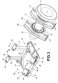
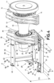
- the tool is intended to transport a power train subset formed at least by the following elements: a shaft, called low-speed shaft (10), along with at least a first bearing (11) mounted on the low-speed shaft (10), and a first support (12) intended to support the first bearing (11) and the low-speed shaft (10) on a frame (not shown) of the wind turbine, and wherein the first support (12) comprises a first arm (13) and a second arm (14).
- the tool comprises a first support element (15) which, in turn, incorporates a first resting surface (16) to allow the first support element (15) to rest on a floor.
- the first support element (15) further comprises a first support surface (17) and a second support surface (18) so that the first arm (13) and the second arm (14), respectively, can rest on the same.
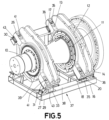
- first distance (D1) Between the first support surface (17) and the first resting surface (16) is a first distance (D1), and between the second support surface (18) and said first resting surface (16) is a second distance (D2), wherein the first distance D1 and the second distance D2 are different.
- first distance (D1) and the second distance (D2) homologous reference points are preferably taken on the first support surface (17) and on the second support surface (18), especially when said first (17) and second (18) support surfaces are not horizontal. For example, the lowest points of each one of them may be taken as a reference, as seen in the figures.
- the power train subset has an actual maximum width (AR), as well as a maximum transport width (AT), which corresponds to a projection of the actual maximum width (AR) on a horizontal plane.
- AR actual maximum width
- AT maximum transport width
- the previously described invention allows the power train subset to incline, from which the maximum transport width (AT) is smaller than the actual maximum width (AR).
- the tool of the invention, along with the power train subset to be introduced in a conventional transport container (not shown).
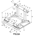
- the first support element (15) incorporates, on the first resting surface (16), a first support body (19) and a second support body (20), one on each right and left side of said first resting surface (16), the first support surface (17) situated on the first support body (19) and the second support surface (18) situated on the second support body (20).
- the tool additionally comprises an additional support element (21) which, in turn, comprises an additional resting surface (22), and on said additional resting surface (22) an additional support body (23), provided with at least an additional support surface (24) on the upper part thereof for supporting one end of the low-speed shaft (10) longitudinally opposite the first support element (15).
- the power train subset can additionally incorporate a second bearing (39) mounted on the low-speed shaft (10), as well as a second support (25) to fasten the second bearing (39) to the low-speed shaft (10), and which, in turn, is provided with a third arm (26) and a fourth arm (27).
- the tool additionally comprises a second support element (28) which, in turn, comprises a second resting surface (29) to allow the second support element (28) to rest on a floor in a stable way.
- the second support element (28) further comprises a third support surface (30) and a fourth support surface (31) so that the third arm (26) and the fourth arm (27) of the second support (25) can rest on the same.
- the third distance D3 and the fourth distance D4 are respectively equal to the first distance (D1) and the second distance (D2).
- the homologous reference points are preferably taken on the third support surface (30) and the fourth support surface (31), especially when said third (30) and fourth (31) support surfaces are not horizontal. For example, the lowest points of each one of them may be taken as a reference, as seen in the figures.
- the second support element (28) preferably comprises, on the second resting surface (29), a third support body (32) and a fourth support body (33), one on each right and left side of said second resting surface (29), wherein the third support surface (30) is situated on the third support body (32) and the fourth support surface (31) is situated on the fourth support body (33).
- the tool preferably comprises a longitudinal direction of the tool, the first support body (19) and the second support body (20) being located on the same first section along the longitudinal direction of the tool.
- the third support body (32) and the fourth support body (33) are preferably located on the same second section along the longitudinal direction of the tool.
- any one, several, or all of the first (17), second (18), third (30) and fourth (31) support surfaces are inclined with respect to a horizontal plane.
- the support bodies (19, 20, 23, 32, 33) can comprise vertical beams.
- the first (19) and/or second (20) support bodies can comprise first beams
- the third (32) and fourth (33) support bodies can comprise second beams
- the additional support body (23) can comprise a third beam.
- any one, several, or all of the first (17), second (18), third (30) and fourth (31) support surfaces have a greater area than the surface of the corresponding arm (13, 14, 26, 27) that rests on the same.
- first (17), second (18), third (30), fourth (31) and additional (24) support surfaces comprise fastening means to be fastened in a separable way to the corresponding arms (13, 14, 26, 27).
- first (17) and/or second (18) support surfaces can comprise first fastening means
- third (30) and/or fourth (31) support surfaces can comprise second fastening means
- additional support surface (24) can comprise third fastening means.
- the fastening means preferably comprise holes (34, 40, 42) made on the first (17), second (18), third (30), fourth (31) and additional (24) support surfaces; as well as bolts (35, 41) for cooperating with the holes (34, 40).
- first fastening means comprise first bolts (35) and first holes (34)
- second fastening means comprise second bolts (41) and second holes (40)
- third fastening means comprise third bolts (not shown) and third holes (42).
- the holes (34, 40, 42) are preferably perpendicular to the corresponding first (17), second (18), third (30), fourth (31) and additional (24) surfaces thereof.
- the fastening means can preferably comprise clamps. Instead of having third fastening means, the end of the low-speed shaft (10) could simply rest on the additional support surface (24).
- the fastening means in particular the holes (34, 40) can be used as reference points for measuring the heights (D1, D2, D3, D4).
- the first (17), second (18), third (30), fourth (31) and additional (24) support surfaces comprise positioning elements (36, 43, 44) for longitudinally and/or transversally positioning the corresponding arms (13, 14, 26, 27) and, if applicable, the corresponding end of the low-speed shaft (10).
- the positioning elements (36, 43, 44) comprise: first positioning elements (36) for the first (17) and second (18) support surfaces, second positioning elements (43) for the third (30) and fourth (31) support surfaces; and third positioning elements (44) for the additional support surface (24).
- the positioning elements (36, 43, 44) are preferably located on a lower area, and/or on a side area of the first (17), second (18), third (30), fourth (31) and additional (24) support surfaces.
- the positioning elements (36, 43, 44) act as stops that limit the movement of the arms (13, 14, 26, 27) and of the low-speed shaft (10), if necessary.
- the first (17) and third (30) support surfaces can form part of a single body, for example a beam.
- the second (18) and fourth (31) support surfaces are shown as separated bodies, they can likewise form part of a single body, a beam for example.
- the first support element (15) and the second support element (28), and optionally, if necessary, the first support element (15) and the additional support element (21), are connected to each other.
- the tool incorporates a base (37), which the first resting surface (16) and/or the second resting surface (29) and/or the additional resting surface (22) form part of, or are connected to, wherein the first support element (15) and/or the additional support element (21) or the first support element (15) and/or the second support element (28) are able to be coupled or are coupled to said base (37).
- first support element (15) and the second support element (28), as well as the first support element (15) and the additional support element (21) are able to be coupled or are coupled by means of connection elements (38), such as plates, bars, frames, etc.
- the power train subset can additionally comprise a gearbox (not shown), coupled to the low-speed shaft (10) and which comprises at least a lateral support element, which additionally comprises:
Landscapes
- Engineering & Computer Science (AREA)
- General Engineering & Computer Science (AREA)
- Mechanical Engineering (AREA)
- Life Sciences & Earth Sciences (AREA)
- Sustainable Development (AREA)
- Sustainable Energy (AREA)
- Chemical & Material Sciences (AREA)
- Combustion & Propulsion (AREA)
- Wind Motors (AREA)
Claims (28)
- Gestell zum Transportieren eines Triebstrangs einer Windturbine, wobei der Triebstrang Folgendes umfasst: eine langsam laufende Welle (10), mindestens ein erstes Lager (11), das auf der langsam laufenden Welle (10) montiert ist, und mindestens eine erste Stütze (12) zum Stützen des ersten Lagers (11) auf der langsam laufenden Welle (10), wobei die erste Stütze (12) mit einem ersten Arm (13) und einem zweiten Arm (14) versehen ist, und wobei das Gestell ein erstes Stützelement (15) umfasst, das seinerseits Folgendes umfasst:- eine erste Auflagefläche (16), damit das Gestell auf dem Boden aufliegen kann, und- eine erste Stützfläche (17) und eine zweite Stützfläche (18), die dazu konfiguriert sind, den ersten Arm (13) und den zweiten Arm (14) des Triebstrangs einer Windturbine zu stützen,wobei das Gestell dadurch gekennzeichnet ist, dass ein erster Abstand (D1) zwischen der ersten Stützfläche (17) und der ersten Auflagefläche (16) vorhanden ist, wobei sich der erste Abstand (D1) von einem zweiten Abstand (D2) zwischen der zweiten Stützfläche (18) und der ersten Auflagefläche (16) unterscheidet undwobei eine, mehrere oder alle der ersten (17) und zweiten (18) Stützflächen in Bezug auf eine horizontale Ebene geneigt sind.
- Gestell nach Anspruch 1, dadurch gekennzeichnet, dass die erste Auflagefläche (16) eine rechte und eine linke Seite umfasst, wobei das erste Stützelement (15) auf der ersten Auflagefläche (16) einen ersten Stützkörper (19) und einen zweiten Stützkörper (20) umfasst, jeweils einen auf der rechten und der linken Seite der ersten Auflagefläche (16), wobei die erste Stützfläche (17) auf dem ersten Stützkörper (19) und die zweite Stützfläche (18) auf dem zweiten Stützkörper (20) angeordnet ist.
- Gestell nach Anspruch 2, dadurch gekennzeichnet, dass es eine Längsrichtung des Werkzeugs umfasst, wobei der erste Stützkörper (19) und der zweite Stützkörper (20) in demselben ersten Querschnitt entlang der Längsrichtung des Gestells angeordnet sind.
- Gestell nach einem der Ansprüche 1-3, dadurch gekennzeichnet, dass eine, mehrere oder alle der ersten (17) und zweiten (18) Stützflächen einen größeren Bereich aufweisen als die Oberfläche des ersten Arms (13) und des zweiten Arms (14) des Triebstrangs einer Windturbine, die auf denselben ruhen.
- Gestell nach einem der Ansprüche 1-4, dadurch gekennzeichnet, dass eine, mehrere oder alle der ersten (17) und zweiten (18) Stützflächen erste Befestigungsmittel umfassen, die auf trennbare Weise an dem ersten Arm (13) und dem zweiten Arm (14) des Triebstrangs einer Windturbine zu befestigen sind.
- Gestell nach Anspruch 5, dadurch gekennzeichnet, dass die ersten Befestigungsmittel Folgendes umfassen:- erste Löcher (34), die in die ersten (17) und zweiten (18) Stützflächen eingebracht sind; und- erste Bolzen (35) zum Zusammenwirken mit den ersten Löchern (34).
- Gestell nach Anspruch 6, dadurch gekennzeichnet, dass die ersten Löcher (34) senkrecht zu den ersten (17) und zweiten (18) Auflageflächen verlaufen.
- Gestell nach einem der Ansprüche 1-7, dadurch gekennzeichnet, dass die ersten (17) und/oder zweiten (18) Auflageflächen erste Positionierelemente (36) zur Längs- und/oder Querpositionierung des ersten Arms (13) und des zweiten Arms (14) des Triebstrangs einer Windturbine umfassen.
- Gestell nach Anspruch 8, dadurch gekennzeichnet, dass die ersten Positionierelemente (36) in einem unteren Bereich und/oder in einem Seitenbereich der ersten (17) und/oder zweiten (18) Auflageflächen angeordnet sind.
- Gestell nach einem der Ansprüche 2 bis 9, dadurch gekennzeichnet, dass der erste (19) und der zweite (20) Stützkörper erste vertikale Träger umfassen.
- Gestell nach einem der Ansprüche 1-10, das zusätzlich eine Basis (37) umfasst, wobei das erste Stützelement (15) mit der Basis (37) gekoppelt werden kann.
- Gestell nach einem der Ansprüche 1-11, dadurch gekennzeichnet, dass es zusätzlich ein zusätzliches Stützelement (21) umfasst, das seinerseits Folgendes umfasst:- eine zusätzliche Auflagefläche (22) und- auf der zusätzlichen Auflagefläche (22) einen zusätzlichen Stützkörper (23), der im oberen Teil mit mindestens einer zusätzlichen Stützfläche (24) zum Abstützen eines Endes der langsam laufenden Welle (10) versehen ist.
- Gestell nach Anspruch 12, dadurch gekennzeichnet, dass es zusätzlich eine Basis (37) umfasst, die ihrerseits die zusätzliche Auflagefläche (22) umfasst, wobei das zusätzliche Stützelement (21) mit der Basis (37) gekoppelt werden kann.
- Gestell nach einem der Ansprüche 1 bis 11, dadurch gekennzeichnet, dass der Triebstrang zusätzlich ein zweites Lager (39), das auf der langsam laufenden Welle (10) montiert ist, und eine zweite Stütze (25) zum Befestigen des zweiten Lagers (39) an der langsam laufenden Welle (10) umfasst, die mit einem dritten Arm (26) und einem vierten Arm (27) versehen ist, wobei das Gestell zusätzlich ein zweites Stützelement (28) umfasst, das seinerseits Folgendes umfasst:- eine zweite Auflagefläche (29), damit das Gestell auf dem Boden aufliegen kann, und- eine dritte Stützfläche (30) und eine vierte Stützfläche (31), die dazu konfiguriert sind, den jeweiligen dritten Arm (26) und vierten Arm (27) des Triebstrangs einer Windturbine auf demselben zu stützen,wobei ein dritter Abstand (D3) zwischen der dritten Auflagefläche (30) und der zweiten Auflagefläche (29) vorhanden ist, wobei der dritte Abstand (D3) sich von einem vierten Abstand (D4) zwischen der vierten Auflagefläche (31) und der zweiten Auflagefläche (29) unterscheidet.
- Gestell nach Anspruch 14, dadurch gekennzeichnet, dass das zweite Stützelement (28) auf der zweiten Auflagefläche (29) einen dritten Stützkörper (32) und einen vierten Stützkörper (33) umfasst, jeweils einen auf der rechten und linken Seite der zweiten Auflagefläche (29), wobei die dritte Stützfläche (30) auf dem dritten Stützkörper (32) und die vierte Stützfläche (31) auf dem vierten Stützkörper (33) angeordnet ist.
- Gestell nach Anspruch 15, dadurch gekennzeichnet, dass es eine Längsrichtung des Werkzeugs umfasst, wobei der dritte Stützkörper (32) und der vierte Stützkörper (33) in demselben zweiten Querschnitt entlang der Längsrichtung des Gestells angeordnet sind.
- Gestell nach einem der Ansprüche 14-16, dadurch gekennzeichnet, dass eine, mehrere oder alle der dritten (30) und vierten (31) Auflageflächen gegenüber einer horizontalen Ebene geneigt sind.
- Gestell nach einem der Ansprüche 14-17, dadurch gekennzeichnet, dass eine, mehrere oder alle der dritten (30) und vierten (31) Auflageflächen einen größeren Bereich aufweisen als die Oberfläche des dritten Arms (26) und des vierten Arms (27) des Triebstrangs einer Windturbine, die auf denselben ruhen.
- Gestell nach einem der Ansprüche 14 bis 18, dadurch gekennzeichnet, dass die dritte (30) und die vierte (31) Stützfläche zweite Befestigungsmittel umfassen, die auf trennbare Weise am dritten Arm (26) und am vierten Arm (27) des Triebstrangs einer Windturbine zu befestigen sind.
- Gestell nach Anspruch 19, dadurch gekennzeichnet, dass die zweiten Befestigungsmittel Folgendes umfassen:- zweite Löcher (40), die in die dritten (30) und vierten (31) Stützflächen eingebracht sind; und- zweite Bolzen (41) zum Zusammenwirken mit den zweiten Löchern (40).
- Gestell nach Anspruch 20, dadurch gekennzeichnet, dass die zweiten Löcher (40) senkrecht zu den dritten (30) und vierten (31) Auflageflächen verlaufen.
- Gestell nach einem der Ansprüche 5 oder 19, dadurch gekennzeichnet, dass die Befestigungsmittel Klammern umfassen.
- Gestell nach einem der Ansprüche 14-22, dadurch gekennzeichnet, dass die dritte (30) und vierte (31) Auflagefläche zweite Positionierelemente (43) zur Längs- und/oder Querpositionierung des dritten Arms (26) und des vierten Arms (27) des Triebstrangs einer Windturbine umfassen.
- Gestell nach Anspruch 23, dadurch gekennzeichnet, dass die zweiten Positionierelemente (43) in einem unteren Bereich und/oder in einem Seitenbereich der dritten (30) und/oder vierten (31) Auflagefläche angeordnet sind.
- Gestell nach einem der Ansprüche 15-24, dadurch gekennzeichnet, dass der dritte (32) und der vierte (33) Stützkörper zweite vertikale Träger umfassen.
- Gestell nach einem der Ansprüche 14 bis 25, das zusätzlich eine Basis (37) umfasst, wobei das zweite Stützelement (28) mit der Basis (37) gekoppelt werden kann.
- Gestell nach einem der Ansprüche 1 und 14, dadurch gekennzeichnet, dass der dritte Abstand (D3) im Wesentlichen gleich dem ersten Abstand (D1) ist und/oder der vierte Abstand (D4) im Wesentlichen gleich dem zweiten Abstand (D2) ist.
- Gestell nach Anspruch 1, 12 und 14, dadurch gekennzeichnet, dass es zusätzlich eine Basis (37) umfasst, die ihrerseits die erste Auflagefläche (16) und die zweite Auflagefläche (29) oder die erste Auflagefläche (16) und die zusätzliche Auflagefläche (22) umfasst, wobei das erste Stützelement (15), das zweite Stützelement (28) und das zusätzliche Stützelement (21) jeweils mit der Basis (37) gekoppelt werden können.
Applications Claiming Priority (1)
| Application Number | Priority Date | Filing Date | Title |
|---|---|---|---|
| ES201731530U ES1203662Y (es) | 2017-12-18 | 2017-12-18 | Utillaje de transporte de un subconjunto de un tren de potenciade un aerogenerador |
Publications (2)
| Publication Number | Publication Date |
|---|---|
| EP3499028A1 EP3499028A1 (de) | 2019-06-19 |
| EP3499028B1 true EP3499028B1 (de) | 2024-05-01 |
Family
ID=60992870
Family Applications (1)
| Application Number | Title | Priority Date | Filing Date |
|---|---|---|---|
| EP18382813.6A Active EP3499028B1 (de) | 2017-12-18 | 2018-11-16 | Gestell zum transport eines triebstrangs einer windturbine |
Country Status (4)
| Country | Link |
|---|---|
| US (1) | US10935000B2 (de) |
| EP (1) | EP3499028B1 (de) |
| DK (1) | DK3499028T3 (de) |
| ES (2) | ES1203662Y (de) |
Families Citing this family (1)
| Publication number | Priority date | Publication date | Assignee | Title |
|---|---|---|---|---|
| US11668430B2 (en) * | 2020-09-30 | 2023-06-06 | Robert Green | Engine mount stand |
Family Cites Families (11)
| Publication number | Priority date | Publication date | Assignee | Title |
|---|---|---|---|---|
| US4804162A (en) * | 1987-06-29 | 1989-02-14 | Joseph M. Rice | Adjustable engine support |
| JP4363799B2 (ja) * | 2001-06-08 | 2009-11-11 | 株式会社東芝 | タービン組立輸送架台および同架台を用いたタービン組立方法、輸送方法 |
| US7726182B1 (en) * | 2008-12-30 | 2010-06-01 | Newlin Mark A | Engine test stand assembly |
| KR20120063777A (ko) * | 2010-12-08 | 2012-06-18 | 현대자동차주식회사 | 차체 이송 대차 |
| KR101258656B1 (ko) * | 2011-03-08 | 2013-04-26 | 주식회사 평산 | 풍력 발전용 샤프트 고정구 |
| DE102011013844A1 (de) * | 2011-03-14 | 2012-09-20 | Repower Systems Ag | Transportgestell für den Triebstrang einer Windenergieanlage |
| CN104364521B (zh) * | 2012-06-10 | 2017-06-06 | 维斯塔斯风力系统有限公司 | 风轮机的主轴承装置 |
| DE102013003191A1 (de) * | 2013-02-26 | 2014-09-11 | F.A. KRUSE jun. ENERGY SERVICES + LOGISTICS GmbH | Kombination aus einem Nabenverkleidungssegment einer Windkraftanlage und einem das Nabenverkleidungssegment tragenden Transportgestell sowie Transportgestell und Verfahren zum Transport eines Nabenverkleidungssegments einer Windkraftanlage |
| KR101482573B1 (ko) * | 2013-03-22 | 2015-01-21 | 두산중공업 주식회사 | 가스터빈용 지지장치 |
| KR101459465B1 (ko) * | 2013-06-14 | 2014-11-07 | 현대자동차 주식회사 | 트렁크 리드 및 테일 게이트 공용 로딩 지그장치 |
| US8876448B1 (en) * | 2013-08-28 | 2014-11-04 | General Electric Company | Gas turbine half-casing shipping fixture |
-
2017
- 2017-12-18 ES ES201731530U patent/ES1203662Y/es active Active
-
2018
- 2018-11-16 ES ES18382813T patent/ES2983531T3/es active Active
- 2018-11-16 EP EP18382813.6A patent/EP3499028B1/de active Active
- 2018-11-16 DK DK18382813.6T patent/DK3499028T3/da active
- 2018-12-18 US US16/223,851 patent/US10935000B2/en active Active
Also Published As
| Publication number | Publication date |
|---|---|
| US20190186466A1 (en) | 2019-06-20 |
| EP3499028A1 (de) | 2019-06-19 |
| DK3499028T3 (da) | 2024-07-08 |
| US10935000B2 (en) | 2021-03-02 |
| BR202018076433U2 (pt) | 2019-06-25 |
| ES2983531T3 (es) | 2024-10-23 |
| ES1203662U (es) | 2018-01-24 |
| ES1203662Y (es) | 2018-04-18 |
Similar Documents
| Publication | Publication Date | Title |
|---|---|---|
| US10473363B2 (en) | Node, support frame, system and method | |
| US9260875B2 (en) | Support arrangement of a wind turbine tower | |
| US9810220B2 (en) | Method of transporting rotating equipment modularization | |
| US10040579B1 (en) | Shipping frame for jet aircraft engine transportation | |
| JP6942264B2 (ja) | 風力タービンのタワーセグメントの事前組立ておよび/または輸送および/または組立て用のフランジフレームおよび組立てセット、および方法 | |
| EP3135833A1 (de) | Drehgelenk, rahmenbausatz, rahmenstruktur mit drehgelenken und verfahren zur herstellung eines drehgelenks | |
| EP3078847B1 (de) | Wartungswerkzeug für ein planetengetriebe und wartungsverfahren | |
| WO2017134902A1 (ja) | 保持治具 | |
| CN107407456B (zh) | 驱动组件 | |
| EP2843810A1 (de) | Generator für eine Windturbine | |
| EP3115601B1 (de) | Verbindung zwischen gittermast und gondel | |
| US10935000B2 (en) | Tool for transporting a wind turbine power train subset | |
| CA2781328C (en) | Node, support frame, system and method | |
| EP3251893B1 (de) | Umwandelbare tragstrukturen zum versenden grosser maschinen | |
| US20140144276A1 (en) | Parallel manipulator | |
| TW202248528A (zh) | 含有具偏移重心之機艙之風力機 | |
| KR101156098B1 (ko) | 가공삭도의 가변시공 방법 및 가변형 가공삭도 | |
| JP6205513B1 (ja) | 球面すべり支承の施工方法、固定治具付き球面すべり支承、および固定治具 | |
| US20170157616A1 (en) | Transmission holder for a roller press and method for dismantling the transmission of a roller press | |
| JP3174326U (ja) | 水平多関節型搬送装置 | |
| CN106381950B (zh) | 单元式幕墙支架系统 | |
| EP3571395B1 (de) | Verfahren zur montage von zwei windturbinenkomponenten mit einer montagehilfsvorrichtung | |
| JPH07102906A (ja) | タービン輸送用架台、タービン輸送方法、タービン補修方法、及びタービン保管方法 | |
| JP2017154882A (ja) | 吊りビーム装置 | |
| KR101559667B1 (ko) | 다중 가공 삭도 |
Legal Events
| Date | Code | Title | Description |
|---|---|---|---|
| PUAI | Public reference made under article 153(3) epc to a published international application that has entered the european phase |
Free format text: ORIGINAL CODE: 0009012 |
|
| STAA | Information on the status of an ep patent application or granted ep patent |
Free format text: STATUS: THE APPLICATION HAS BEEN PUBLISHED |
|
| AK | Designated contracting states |
Kind code of ref document: A1 Designated state(s): AL AT BE BG CH CY CZ DE DK EE ES FI FR GB GR HR HU IE IS IT LI LT LU LV MC MK MT NL NO PL PT RO RS SE SI SK SM TR |
|
| AX | Request for extension of the european patent |
Extension state: BA ME |
|
| STAA | Information on the status of an ep patent application or granted ep patent |
Free format text: STATUS: REQUEST FOR EXAMINATION WAS MADE |
|
| 17P | Request for examination filed |
Effective date: 20200331 |
|
| RBV | Designated contracting states (corrected) |
Designated state(s): AL AT BE BG CH CY CZ DE DK EE ES FI FR GB GR HR HU IE IS IT LI LT LU LV MC MK MT NL NO PL PT RO RS SE SI SK SM TR |
|
| STAA | Information on the status of an ep patent application or granted ep patent |
Free format text: STATUS: EXAMINATION IS IN PROGRESS |
|
| 17Q | First examination report despatched |
Effective date: 20220406 |
|
| P01 | Opt-out of the competence of the unified patent court (upc) registered |
Effective date: 20230530 |
|
| GRAP | Despatch of communication of intention to grant a patent |
Free format text: ORIGINAL CODE: EPIDOSNIGR1 |
|
| STAA | Information on the status of an ep patent application or granted ep patent |
Free format text: STATUS: GRANT OF PATENT IS INTENDED |
|
| INTG | Intention to grant announced |
Effective date: 20231201 |
|
| RIN1 | Information on inventor provided before grant (corrected) |
Inventor name: NUNEZ POLO, MIGUEL Inventor name: GARCIA SAYES, JOSE MIGUEL Inventor name: ARLABAN GABEIRAS, TERESA Inventor name: GASTON LUJAMBO, ANDER Inventor name: IRURITA LOYARTE, JUAN Inventor name: ARRAZTOA MAGANA, UNAI Inventor name: RUEDA ALZUGARAY, DIEGO Inventor name: VALLE MARTIN, ANDRES Inventor name: AUGUSTO LIZARRAGA, NURIA |
|
| GRAS | Grant fee paid |
Free format text: ORIGINAL CODE: EPIDOSNIGR3 |
|
| GRAA | (expected) grant |
Free format text: ORIGINAL CODE: 0009210 |
|
| STAA | Information on the status of an ep patent application or granted ep patent |
Free format text: STATUS: THE PATENT HAS BEEN GRANTED |
|
| AK | Designated contracting states |
Kind code of ref document: B1 Designated state(s): AL AT BE BG CH CY CZ DE DK EE ES FI FR GB GR HR HU IE IS IT LI LT LU LV MC MK MT NL NO PL PT RO RS SE SI SK SM TR |
|
| REG | Reference to a national code |
Ref country code: GB Ref legal event code: FG4D |
|
| REG | Reference to a national code |
Ref country code: CH Ref legal event code: EP |
|
| REG | Reference to a national code |
Ref country code: IE Ref legal event code: FG4D |
|
| REG | Reference to a national code |
Ref country code: DE Ref legal event code: R096 Ref document number: 602018068830 Country of ref document: DE |
|
| REG | Reference to a national code |
Ref country code: DK Ref legal event code: T3 Effective date: 20240704 |
|
| REG | Reference to a national code |
Ref country code: LT Ref legal event code: MG9D |
|
| REG | Reference to a national code |
Ref country code: NL Ref legal event code: MP Effective date: 20240501 |
|
| PG25 | Lapsed in a contracting state [announced via postgrant information from national office to epo] |
Ref country code: IS Free format text: LAPSE BECAUSE OF FAILURE TO SUBMIT A TRANSLATION OF THE DESCRIPTION OR TO PAY THE FEE WITHIN THE PRESCRIBED TIME-LIMIT Effective date: 20240901 |
|
| PG25 | Lapsed in a contracting state [announced via postgrant information from national office to epo] |
Ref country code: BG Free format text: LAPSE BECAUSE OF FAILURE TO SUBMIT A TRANSLATION OF THE DESCRIPTION OR TO PAY THE FEE WITHIN THE PRESCRIBED TIME-LIMIT Effective date: 20240501 |
|
| PG25 | Lapsed in a contracting state [announced via postgrant information from national office to epo] |
Ref country code: FI Free format text: LAPSE BECAUSE OF FAILURE TO SUBMIT A TRANSLATION OF THE DESCRIPTION OR TO PAY THE FEE WITHIN THE PRESCRIBED TIME-LIMIT Effective date: 20240501 Ref country code: HR Free format text: LAPSE BECAUSE OF FAILURE TO SUBMIT A TRANSLATION OF THE DESCRIPTION OR TO PAY THE FEE WITHIN THE PRESCRIBED TIME-LIMIT Effective date: 20240501 |
|
| PG25 | Lapsed in a contracting state [announced via postgrant information from national office to epo] |
Ref country code: GR Free format text: LAPSE BECAUSE OF FAILURE TO SUBMIT A TRANSLATION OF THE DESCRIPTION OR TO PAY THE FEE WITHIN THE PRESCRIBED TIME-LIMIT Effective date: 20240802 |
|
| PG25 | Lapsed in a contracting state [announced via postgrant information from national office to epo] |
Ref country code: PT Free format text: LAPSE BECAUSE OF FAILURE TO SUBMIT A TRANSLATION OF THE DESCRIPTION OR TO PAY THE FEE WITHIN THE PRESCRIBED TIME-LIMIT Effective date: 20240902 |
|
| REG | Reference to a national code |
Ref country code: AT Ref legal event code: MK05 Ref document number: 1682655 Country of ref document: AT Kind code of ref document: T Effective date: 20240501 |
|
| PG25 | Lapsed in a contracting state [announced via postgrant information from national office to epo] |
Ref country code: NL Free format text: LAPSE BECAUSE OF FAILURE TO SUBMIT A TRANSLATION OF THE DESCRIPTION OR TO PAY THE FEE WITHIN THE PRESCRIBED TIME-LIMIT Effective date: 20240501 |
|
| REG | Reference to a national code |
Ref country code: ES Ref legal event code: FG2A Ref document number: 2983531 Country of ref document: ES Kind code of ref document: T3 Effective date: 20241023 |
|
| PG25 | Lapsed in a contracting state [announced via postgrant information from national office to epo] |
Ref country code: AT Free format text: LAPSE BECAUSE OF FAILURE TO SUBMIT A TRANSLATION OF THE DESCRIPTION OR TO PAY THE FEE WITHIN THE PRESCRIBED TIME-LIMIT Effective date: 20240501 |
|
| PG25 | Lapsed in a contracting state [announced via postgrant information from national office to epo] |
Ref country code: PL Free format text: LAPSE BECAUSE OF FAILURE TO SUBMIT A TRANSLATION OF THE DESCRIPTION OR TO PAY THE FEE WITHIN THE PRESCRIBED TIME-LIMIT Effective date: 20240501 |
|
| PG25 | Lapsed in a contracting state [announced via postgrant information from national office to epo] |
Ref country code: LV Free format text: LAPSE BECAUSE OF FAILURE TO SUBMIT A TRANSLATION OF THE DESCRIPTION OR TO PAY THE FEE WITHIN THE PRESCRIBED TIME-LIMIT Effective date: 20240501 |
|
| PG25 | Lapsed in a contracting state [announced via postgrant information from national office to epo] |
Ref country code: PT Free format text: LAPSE BECAUSE OF FAILURE TO SUBMIT A TRANSLATION OF THE DESCRIPTION OR TO PAY THE FEE WITHIN THE PRESCRIBED TIME-LIMIT Effective date: 20240902 Ref country code: PL Free format text: LAPSE BECAUSE OF FAILURE TO SUBMIT A TRANSLATION OF THE DESCRIPTION OR TO PAY THE FEE WITHIN THE PRESCRIBED TIME-LIMIT Effective date: 20240501 Ref country code: NO Free format text: LAPSE BECAUSE OF FAILURE TO SUBMIT A TRANSLATION OF THE DESCRIPTION OR TO PAY THE FEE WITHIN THE PRESCRIBED TIME-LIMIT Effective date: 20240801 Ref country code: NL Free format text: LAPSE BECAUSE OF FAILURE TO SUBMIT A TRANSLATION OF THE DESCRIPTION OR TO PAY THE FEE WITHIN THE PRESCRIBED TIME-LIMIT Effective date: 20240501 Ref country code: LV Free format text: LAPSE BECAUSE OF FAILURE TO SUBMIT A TRANSLATION OF THE DESCRIPTION OR TO PAY THE FEE WITHIN THE PRESCRIBED TIME-LIMIT Effective date: 20240501 Ref country code: IS Free format text: LAPSE BECAUSE OF FAILURE TO SUBMIT A TRANSLATION OF THE DESCRIPTION OR TO PAY THE FEE WITHIN THE PRESCRIBED TIME-LIMIT Effective date: 20240901 Ref country code: HR Free format text: LAPSE BECAUSE OF FAILURE TO SUBMIT A TRANSLATION OF THE DESCRIPTION OR TO PAY THE FEE WITHIN THE PRESCRIBED TIME-LIMIT Effective date: 20240501 Ref country code: GR Free format text: LAPSE BECAUSE OF FAILURE TO SUBMIT A TRANSLATION OF THE DESCRIPTION OR TO PAY THE FEE WITHIN THE PRESCRIBED TIME-LIMIT Effective date: 20240802 Ref country code: FI Free format text: LAPSE BECAUSE OF FAILURE TO SUBMIT A TRANSLATION OF THE DESCRIPTION OR TO PAY THE FEE WITHIN THE PRESCRIBED TIME-LIMIT Effective date: 20240501 Ref country code: BG Free format text: LAPSE BECAUSE OF FAILURE TO SUBMIT A TRANSLATION OF THE DESCRIPTION OR TO PAY THE FEE WITHIN THE PRESCRIBED TIME-LIMIT Effective date: 20240501 Ref country code: AT Free format text: LAPSE BECAUSE OF FAILURE TO SUBMIT A TRANSLATION OF THE DESCRIPTION OR TO PAY THE FEE WITHIN THE PRESCRIBED TIME-LIMIT Effective date: 20240501 Ref country code: RS Free format text: LAPSE BECAUSE OF FAILURE TO SUBMIT A TRANSLATION OF THE DESCRIPTION OR TO PAY THE FEE WITHIN THE PRESCRIBED TIME-LIMIT Effective date: 20240801 |
|
| PG25 | Lapsed in a contracting state [announced via postgrant information from national office to epo] |
Ref country code: EE Free format text: LAPSE BECAUSE OF FAILURE TO SUBMIT A TRANSLATION OF THE DESCRIPTION OR TO PAY THE FEE WITHIN THE PRESCRIBED TIME-LIMIT Effective date: 20240501 |
|
| PG25 | Lapsed in a contracting state [announced via postgrant information from national office to epo] |
Ref country code: CZ Free format text: LAPSE BECAUSE OF FAILURE TO SUBMIT A TRANSLATION OF THE DESCRIPTION OR TO PAY THE FEE WITHIN THE PRESCRIBED TIME-LIMIT Effective date: 20240501 |
|
| PG25 | Lapsed in a contracting state [announced via postgrant information from national office to epo] |
Ref country code: RO Free format text: LAPSE BECAUSE OF FAILURE TO SUBMIT A TRANSLATION OF THE DESCRIPTION OR TO PAY THE FEE WITHIN THE PRESCRIBED TIME-LIMIT Effective date: 20240501 Ref country code: SK Free format text: LAPSE BECAUSE OF FAILURE TO SUBMIT A TRANSLATION OF THE DESCRIPTION OR TO PAY THE FEE WITHIN THE PRESCRIBED TIME-LIMIT Effective date: 20240501 |
|
| PG25 | Lapsed in a contracting state [announced via postgrant information from national office to epo] |
Ref country code: SM Free format text: LAPSE BECAUSE OF FAILURE TO SUBMIT A TRANSLATION OF THE DESCRIPTION OR TO PAY THE FEE WITHIN THE PRESCRIBED TIME-LIMIT Effective date: 20240501 |
|
| PG25 | Lapsed in a contracting state [announced via postgrant information from national office to epo] |
Ref country code: SM Free format text: LAPSE BECAUSE OF FAILURE TO SUBMIT A TRANSLATION OF THE DESCRIPTION OR TO PAY THE FEE WITHIN THE PRESCRIBED TIME-LIMIT Effective date: 20240501 Ref country code: SK Free format text: LAPSE BECAUSE OF FAILURE TO SUBMIT A TRANSLATION OF THE DESCRIPTION OR TO PAY THE FEE WITHIN THE PRESCRIBED TIME-LIMIT Effective date: 20240501 Ref country code: RO Free format text: LAPSE BECAUSE OF FAILURE TO SUBMIT A TRANSLATION OF THE DESCRIPTION OR TO PAY THE FEE WITHIN THE PRESCRIBED TIME-LIMIT Effective date: 20240501 Ref country code: EE Free format text: LAPSE BECAUSE OF FAILURE TO SUBMIT A TRANSLATION OF THE DESCRIPTION OR TO PAY THE FEE WITHIN THE PRESCRIBED TIME-LIMIT Effective date: 20240501 Ref country code: CZ Free format text: LAPSE BECAUSE OF FAILURE TO SUBMIT A TRANSLATION OF THE DESCRIPTION OR TO PAY THE FEE WITHIN THE PRESCRIBED TIME-LIMIT Effective date: 20240501 |
|
| REG | Reference to a national code |
Ref country code: DE Ref legal event code: R097 Ref document number: 602018068830 Country of ref document: DE |
|
| PG25 | Lapsed in a contracting state [announced via postgrant information from national office to epo] |
Ref country code: IT Free format text: LAPSE BECAUSE OF FAILURE TO SUBMIT A TRANSLATION OF THE DESCRIPTION OR TO PAY THE FEE WITHIN THE PRESCRIBED TIME-LIMIT Effective date: 20240501 |
|
| PLBE | No opposition filed within time limit |
Free format text: ORIGINAL CODE: 0009261 |
|
| STAA | Information on the status of an ep patent application or granted ep patent |
Free format text: STATUS: NO OPPOSITION FILED WITHIN TIME LIMIT |
|
| 26N | No opposition filed |
Effective date: 20250204 |
|
| PG25 | Lapsed in a contracting state [announced via postgrant information from national office to epo] |
Ref country code: SI Free format text: LAPSE BECAUSE OF FAILURE TO SUBMIT A TRANSLATION OF THE DESCRIPTION OR TO PAY THE FEE WITHIN THE PRESCRIBED TIME-LIMIT Effective date: 20240501 |
|
| REG | Reference to a national code |
Ref country code: CH Ref legal event code: PL |
|
| PG25 | Lapsed in a contracting state [announced via postgrant information from national office to epo] |
Ref country code: MC Free format text: LAPSE BECAUSE OF FAILURE TO SUBMIT A TRANSLATION OF THE DESCRIPTION OR TO PAY THE FEE WITHIN THE PRESCRIBED TIME-LIMIT Effective date: 20240501 |
|
| PG25 | Lapsed in a contracting state [announced via postgrant information from national office to epo] |
Ref country code: LU Free format text: LAPSE BECAUSE OF NON-PAYMENT OF DUE FEES Effective date: 20241116 |
|
| REG | Reference to a national code |
Ref country code: CH Ref legal event code: PL |
|
| GBPC | Gb: european patent ceased through non-payment of renewal fee |
Effective date: 20241116 |
|
| PG25 | Lapsed in a contracting state [announced via postgrant information from national office to epo] |
Ref country code: CH Free format text: LAPSE BECAUSE OF NON-PAYMENT OF DUE FEES Effective date: 20241130 |
|
| REG | Reference to a national code |
Ref country code: BE Ref legal event code: MM Effective date: 20241130 |
|
| PG25 | Lapsed in a contracting state [announced via postgrant information from national office to epo] |
Ref country code: SE Free format text: LAPSE BECAUSE OF FAILURE TO SUBMIT A TRANSLATION OF THE DESCRIPTION OR TO PAY THE FEE WITHIN THE PRESCRIBED TIME-LIMIT Effective date: 20240501 |
|
| PG25 | Lapsed in a contracting state [announced via postgrant information from national office to epo] |
Ref country code: GB Free format text: LAPSE BECAUSE OF NON-PAYMENT OF DUE FEES Effective date: 20241116 Ref country code: BE Free format text: LAPSE BECAUSE OF NON-PAYMENT OF DUE FEES Effective date: 20241130 |
|
| PG25 | Lapsed in a contracting state [announced via postgrant information from national office to epo] |
Ref country code: FR Free format text: LAPSE BECAUSE OF NON-PAYMENT OF DUE FEES Effective date: 20241130 |
|
| PG25 | Lapsed in a contracting state [announced via postgrant information from national office to epo] |
Ref country code: IE Free format text: LAPSE BECAUSE OF NON-PAYMENT OF DUE FEES Effective date: 20241116 |
|
| PGFP | Annual fee paid to national office [announced via postgrant information from national office to epo] |
Ref country code: DE Payment date: 20251118 Year of fee payment: 8 |
|
| PGFP | Annual fee paid to national office [announced via postgrant information from national office to epo] |
Ref country code: DK Payment date: 20251119 Year of fee payment: 8 |
|
| PGFP | Annual fee paid to national office [announced via postgrant information from national office to epo] |
Ref country code: ES Payment date: 20251216 Year of fee payment: 8 |
|
| PG25 | Lapsed in a contracting state [announced via postgrant information from national office to epo] |
Ref country code: HU Free format text: LAPSE BECAUSE OF FAILURE TO SUBMIT A TRANSLATION OF THE DESCRIPTION OR TO PAY THE FEE WITHIN THE PRESCRIBED TIME-LIMIT; INVALID AB INITIO Effective date: 20181116 |
|
| PG25 | Lapsed in a contracting state [announced via postgrant information from national office to epo] |
Ref country code: CY Free format text: LAPSE BECAUSE OF FAILURE TO SUBMIT A TRANSLATION OF THE DESCRIPTION OR TO PAY THE FEE WITHIN THE PRESCRIBED TIME-LIMIT; INVALID AB INITIO Effective date: 20181116 |