EP3498657A1 - Dispositif pour remplir des récipients avec un produit liquide sous pression - Google Patents
Dispositif pour remplir des récipients avec un produit liquide sous pression Download PDFInfo
- Publication number
- EP3498657A1 EP3498657A1 EP18207298.3A EP18207298A EP3498657A1 EP 3498657 A1 EP3498657 A1 EP 3498657A1 EP 18207298 A EP18207298 A EP 18207298A EP 3498657 A1 EP3498657 A1 EP 3498657A1
- Authority
- EP
- European Patent Office
- Prior art keywords
- sealing
- filling
- receptacle
- opening
- mobile
- Prior art date
- Legal status (The legal status is an assumption and is not a legal conclusion. Google has not performed a legal analysis and makes no representation as to the accuracy of the status listed.)
- Withdrawn
Links
Images


Classifications
-
- B—PERFORMING OPERATIONS; TRANSPORTING
- B67—OPENING, CLOSING OR CLEANING BOTTLES, JARS OR SIMILAR CONTAINERS; LIQUID HANDLING
- B67C—CLEANING, FILLING WITH LIQUIDS OR SEMILIQUIDS, OR EMPTYING, OF BOTTLES, JARS, CANS, CASKS, BARRELS, OR SIMILAR CONTAINERS, NOT OTHERWISE PROVIDED FOR; FUNNELS
- B67C3/00—Bottling liquids or semiliquids; Filling jars or cans with liquids or semiliquids using bottling or like apparatus; Filling casks or barrels with liquids or semiliquids
- B67C3/02—Bottling liquids or semiliquids; Filling jars or cans with liquids or semiliquids using bottling or like apparatus
- B67C3/22—Details
- B67C3/26—Filling-heads; Means for engaging filling-heads with bottle necks
- B67C3/2614—Filling-heads; Means for engaging filling-heads with bottle necks specially adapted for counter-pressure filling
-
- B—PERFORMING OPERATIONS; TRANSPORTING
- B67—OPENING, CLOSING OR CLEANING BOTTLES, JARS OR SIMILAR CONTAINERS; LIQUID HANDLING
- B67C—CLEANING, FILLING WITH LIQUIDS OR SEMILIQUIDS, OR EMPTYING, OF BOTTLES, JARS, CANS, CASKS, BARRELS, OR SIMILAR CONTAINERS, NOT OTHERWISE PROVIDED FOR; FUNNELS
- B67C3/00—Bottling liquids or semiliquids; Filling jars or cans with liquids or semiliquids using bottling or like apparatus; Filling casks or barrels with liquids or semiliquids
- B67C3/02—Bottling liquids or semiliquids; Filling jars or cans with liquids or semiliquids using bottling or like apparatus
- B67C3/06—Bottling liquids or semiliquids; Filling jars or cans with liquids or semiliquids using bottling or like apparatus using counterpressure, i.e. filling while the container is under pressure
-
- B—PERFORMING OPERATIONS; TRANSPORTING
- B67—OPENING, CLOSING OR CLEANING BOTTLES, JARS OR SIMILAR CONTAINERS; LIQUID HANDLING
- B67C—CLEANING, FILLING WITH LIQUIDS OR SEMILIQUIDS, OR EMPTYING, OF BOTTLES, JARS, CANS, CASKS, BARRELS, OR SIMILAR CONTAINERS, NOT OTHERWISE PROVIDED FOR; FUNNELS
- B67C3/00—Bottling liquids or semiliquids; Filling jars or cans with liquids or semiliquids using bottling or like apparatus; Filling casks or barrels with liquids or semiliquids
- B67C3/02—Bottling liquids or semiliquids; Filling jars or cans with liquids or semiliquids using bottling or like apparatus
- B67C3/22—Details
- B67C3/26—Filling-heads; Means for engaging filling-heads with bottle necks
- B67C2003/2657—Filling-heads; Means for engaging filling-heads with bottle necks specially adapted for filling cans
-
- B—PERFORMING OPERATIONS; TRANSPORTING
- B67—OPENING, CLOSING OR CLEANING BOTTLES, JARS OR SIMILAR CONTAINERS; LIQUID HANDLING
- B67C—CLEANING, FILLING WITH LIQUIDS OR SEMILIQUIDS, OR EMPTYING, OF BOTTLES, JARS, CANS, CASKS, BARRELS, OR SIMILAR CONTAINERS, NOT OTHERWISE PROVIDED FOR; FUNNELS
- B67C3/00—Bottling liquids or semiliquids; Filling jars or cans with liquids or semiliquids using bottling or like apparatus; Filling casks or barrels with liquids or semiliquids
- B67C3/02—Bottling liquids or semiliquids; Filling jars or cans with liquids or semiliquids using bottling or like apparatus
- B67C3/22—Details
- B67C3/26—Filling-heads; Means for engaging filling-heads with bottle necks
- B67C2003/266—Means for centering the container with the filling head
-
- B—PERFORMING OPERATIONS; TRANSPORTING
- B67—OPENING, CLOSING OR CLEANING BOTTLES, JARS OR SIMILAR CONTAINERS; LIQUID HANDLING
- B67C—CLEANING, FILLING WITH LIQUIDS OR SEMILIQUIDS, OR EMPTYING, OF BOTTLES, JARS, CANS, CASKS, BARRELS, OR SIMILAR CONTAINERS, NOT OTHERWISE PROVIDED FOR; FUNNELS
- B67C3/00—Bottling liquids or semiliquids; Filling jars or cans with liquids or semiliquids using bottling or like apparatus; Filling casks or barrels with liquids or semiliquids
- B67C3/02—Bottling liquids or semiliquids; Filling jars or cans with liquids or semiliquids using bottling or like apparatus
- B67C3/22—Details
- B67C3/26—Filling-heads; Means for engaging filling-heads with bottle necks
- B67C2003/2668—Means for adapting the filling head to various sizes of containers
Definitions
- the present invention relates to a filling device for a filling machine configured for filling receptacles, in particular receptacles made of metal material, such as cans, with a pourable product at a pressure higher than atmospheric pressure, for example, a carbonated beverage.
- Filling machines typically used in this sector basically comprise a carousel rotating about a vertical axis, a tank containing the pourable product, and a plurality of filling devices carried peripherally by the carousel, connected to the tank by means of respective circuits or ducts and conveyed by the carousel along a circular transfer path.
- the carousel receives a succession of empty receptacles from an input starwheel and conveys the full receptacles towards an output starwheel.
- Each filling device basically comprises a supporting element designed to receive and keep in a vertical position, underneath the device itself, a respective receptacle, and a filling valve configured for supplying a pre-set amount of pourable product into said receptacle, while the filling device moves along the transfer path due to the rotary movement imparted by the carousel.
- filling valves of the known type basically comprise:
- the tubular body has a longitudinal axis parallel to the axis of the carousel and terminates at a bottom end with an axial discharge opening, which communicates fluidically, in use, with an end opening defined by a top edge of the respective receptacle to be filled.
- the channel defined by the tubular body comprises a stretch with constant section, usually cylindrical, and a stretch with variable section, positioned above the discharge opening, which narrows in the direction of the latter down to a section of minimum diameter.
- the shutter is mobile within the channel of the tubular body between:
- known filling valves further comprise two circuits formed at least in part within the tubular body:
- the filling devices of the type described above typically comprise:
- the sealing sleeve is axially mobile between an upper release position, where it is detached from the respective receptacle, and a lower sealing position, where it co-operates in a fluid-tight manner with the top edge of the receptacle to be filled.
- the sealing sleeve is provided with an annular gasket mounted at a bottom axial end of the sleeve itself facing the receptacle, which defines, in use, an axial abutment for the top edge of the respective receptacle and is configured for sealing the latter to the filling valve during the filling process.
- annular gasket mounted at a bottom axial end of the sleeve itself facing the receptacle, which defines, in use, an axial abutment for the top edge of the respective receptacle and is configured for sealing the latter to the filling valve during the filling process.
- the top edge of the aforesaid receptacle delimits, on the gasket of the sealing sleeve, towards the axis of the receptacle itself, an annular working surface having a radial extension proportional to the diameter of the end opening of the aforesaid receptacle.
- the actuator that controls the axial displacement of the sealing sleeve comprises a mobile member set in a position axially corresponding to the top axial portion of the filling device and mechanically connected to the sealing sleeve so that an axial movement of the mobile member there corresponds to an axial movement of the sealing sleeve.
- the actuator comprises a helical spring configured for exerting a downward force on the mobile member. This force consequently acts on the sealing sleeve so as to determine an axial movement of the latter towards its own sealing position. In this way, the gasket of the sleeve can bear, in a fluid-tight manner, upon the top edge of the receptacle to be filled.
- the helical spring pre-loads the mobile member with the aforesaid force and hence pushes the sealing sleeve, integral with the mobile member, on the top edge of the receptacle to be filled.
- the filling device further comprises a cam-follower roller integral with the mobile member and configured to co-operate with a fixed cam, mounted on the peripheral portion of the carousel and extending through a certain angle about the axis of the latter.
- the roller rolls on the cam cyclically through the aforesaid angle, at each turn of the carousel about its own axis.
- the cam has:
- the roller is configured for moving the mobile member axially when it co-operates with the release or attack portions.
- the mobile member When the roller co-operates with the attack portion of the cam, the mobile member is gradually displaced downwards, following the force of the helical spring, and the sealing sleeve is consequently displaced towards its own sealing position.
- the sealing sleeve When the roller co-operates with the central portion of the cam, the sealing sleeve is held in the release position, and a change of the receptacle is performed: the filled receptacle is conveyed towards the output starwheel and a new receptacle to be filled is positioned underneath the filling device.
- the operation is repeated cyclically by each filling device of the filling machine present in the carousel.
- the sealing sleeve is subject to a certain pressure exerted by the pressurising gas on the aforesaid working surface, within the receptacle, and on the opposite surface of the sleeve itself.
- This pressure generates two opposed forces on the aforesaid surfaces: a first force directed downwards, which pushes the sealing sleeve towards the receptacle, and a second upward force, opposed to the first force.
- the intensity of the second force is proportional to the extension of the working surface, which increases as the inner diameter of the receptacle to be filled increases.
- number 1 indicates as a whole a filling machine configured for filling a plurality of receptacles 2 with a pourable product at a pressure value higher than atmospheric pressure.
- the receptacles 2 are made of metallic material, and the pourable product is a liquid with the addition of gas under pressure, for example a carbonated beverage.
- the machine 1 comprises a rotary conveyor, preferably a carousel 3, configured for turning about a vertical axis A, and a tank 5 containing the pourable product under pressure and positioned peripherally with respect to the carousel 3 itself.
- the carousel 3 receives a succession of empty receptacles 2 from an input starwheel (not illustrated), and directs the full receptacles 2 towards an output starwheel (not illustrated either).
- the carousel 3 carries in cantilever manner, at a peripheral portion 3a thereof, a plurality of filling devices 4 configured for filling respective receptacles 2 up to a pre-set level during the rotation of the carousel 3 about the axis A.
- the filling devices 4 are hence conveyed by the carousel 3 along a circular transfer path in respective positions at equal radially equidistant about the axis A.
- each filling device 4 is fluidically connected to the tank 5 by means of a circuit 6 configured for conveying the pourable product from the tank 5 to the filling device 4.
- each receptacle 2 is defined by a substantially cylindrical can, which has a longitudinal axis B and is fed, in a vertical position, by the carousel 3.
- each receptacle 2 is fed by the carousel 3 with its own axis B parallel to the axis A of the carousel 3 itself and in a lower position with respect to the corresponding filling device 4.
- each receptacle 2 has a body 7 coaxial with axis B and delimited at the top by an annular edge 9, which delimits a circular end opening 9a of the receptacle 2 itself.
- each filling device 4 further comprises a filling valve 8, which can be selectively activated for controlling outflow of the pourable product into a respective receptacle 2 to be filled.
- a filling valve 8 which can be selectively activated for controlling outflow of the pourable product into a respective receptacle 2 to be filled.
- the edge 9 of the receptacle 2 is set in contact with the filling valve 8 itself so as to receive from the latter the pourable product in a fluid-tight condition.
- each filling device 4 is configured for carrying out a so-called contact filling operation, where the respective receptacle 2 is supported in fluid-tight contact against the corresponding filling valve 8.
- the above filling valve 8 basically comprises:
- the tubular body 11 has a top end portion 14, an intermediate portion 17 provided with a transverse inlet opening 15 configured for receiving the pourable product from the tank 5 through the circuit 6, and a bottom end portion 16 terminating with an axial outlet opening 18 configured for supplying the pourable product into the respective receptacle 2.
- the channel 12 comprises, at the bottom end portion 16 of the tubular body 11, a portion 22 with variable section, which defines the terminal part of the channel 12 itself.
- the portion 22 comprises two frustoconical stretches 23, 24.
- the stretch 23 is positioned upstream of the stretch 24 with respect to the direction of feed of the pourable product into the channel 12; i.e. it is set in a higher position with respect to the stretch 24, and has a cross section that tapers towards the latter; the stretch 24 has, instead, a diameter increasing from the stretch 23 to the outlet opening 18.
- the two stretches 23, 24 define a narrow section 25 between them.
- the shutter 13 is mounted coaxially within the channel 12 of the tubular body 11.
- the shutter 13 comprises an externally cylindrical top portion 26, a bottom portion 27, having a diameter larger than the diameter of the top portion 26 and extending axially from the latter in the direction of the outlet opening 18, and a shaped terminal portion 27a, configured for co-operating with the portion of the tubular body 11 that defines the portion 22 with variable section of the channel 12.
- the terminal portion 27a is provided with a sealing ring 28, preferably an O-ring made of elastomeric material, configured for co-operating selectively in a fluid-tight manner with the narrow section 25 of the channel 12 so as to prevent the outflow of the pourable product into the outlet opening 18 and, hence, into the receptacle 2 to be filled.
- a sealing ring 28 preferably an O-ring made of elastomeric material, configured for co-operating selectively in a fluid-tight manner with the narrow section 25 of the channel 12 so as to prevent the outflow of the pourable product into the outlet opening 18 and, hence, into the receptacle 2 to be filled.
- the shutter 13 is mobile within the channel 12 of the tubular body 11 between:
- the movement of the shutter 13 from the closed position to the open position is obtained via the actuator 30, the latter preferably being a fluid actuator, for example a pneumatic piston coupled to the shutter 13 in a known way not described in detail.
- the actuator 30 preferably being a fluid actuator, for example a pneumatic piston coupled to the shutter 13 in a known way not described in detail.
- the movement of the shutter 13 could be obtained by means of a mechanical or electromagnetic actuator.
- each filling device 4 further comprises a supporting element 55 (only one of which is illustrated in Figure 5 ) designed to receive and keep a respective receptacle 2 in a vertical position.
- the latter is kept in a lower position with respect to the filling device 4 and coaxial with the axis C at least during activation of the filling valve 8.
- the machine 1 further comprises:
- the pressurising/discharging circuit 31 comprises, for each filling device 4, a duct 33 that fluidically connects the internal environment of the respective receptacle 2 to an annular chamber 34 of the pressurising/discharging circuit 31 itself, which is provided in the carousel 3 and contains a gas under pressure, for example carbon dioxide.
- the duct 33 further comprises a flow-control valve 35, preferably of a pneumatic type, configured for enabling or preventing flow of the gas under pressure from or towards the chamber 32.
- the decompression circuit 32 comprises, for each filling device 4, a duct 36 that fluidically connects the internal environment of the respective receptacle 2 to an annular chamber 37 provided in the carousel 3.
- the chamber 37 is kept at a pressure lower than the pressure inside the receptacle 2 at the end of filling and can in turn be connected to the external environment at atmospheric pressure in a known way not described in detail.
- the duct 36 further comprises a flow-control valve 38, preferably of a pneumatic type, configured for selectively opening or closing the fluidic communication between the chamber 37 and the duct 36.
- each filling device 4 comprises a sealing sleeve 19 axially slidable, in use, through a purposely provided annular seat 20 provided in the end portion 16 of the tubular body 11.
- the sleeve 19 is axially slidable through the seat 20 between a upper release position, where it is at a certain distance from the edge 9 of the respective receptacle 2 and is located at least partially within the seat 20, and a lower sealing position, where it is almost totally extracted from the seat 20 itself and co-operates, in use, in a fluid-tight manner with the edge 9 of the respective receptacle 2.
- the sleeve 19 comprises, at an axial end thereof facing, in use, the receptacle 2, an annular gasket 21, which has a sealing surface 21a that defines, in use, an axial abutment for the edge 9 of the respective receptacle 2.
- the sealing surface 21a co-operates, in use, in a fluid-tight manner with the edge 9 during the filling process. In this way, the internal volume of the body 7 of the aforesaid receptacle 2 is maintained in fluid-tight conditions throughout this process.
- each filling device 4 further comprises elastic means, in particular a gas spring 56, which have an elastic stiffness that can be selectively modified according to the diameter of the opening 9a delimited by the edge 9 of the respective receptacle 2.
- the gas spring 56 comprises a mobile member, preferably a plunger 40 that is axially slidable, in use, within an axial compartment 39 provided at the top end portion 14 of the tubular body 11.
- the plunger 40 delimits, on one side of the compartment 39, a sealed top chamber 41, configured to be filled with a gas, for example air, at a pre-set pressure value P0 that can be modified according to the diameter of the opening 9a of the respective receptacle 2.
- a gas for example air
- said pressure value P0 defines the elastic stiffness of the gas spring 56.
- the top chamber 41 is configured for being selectively filled at different pressure values proportional to the diameter of the opening 9a of receptacles 2 of different format and/or size.
- the plunger 40 moreover delimits, on the side of the compartment 39 axially opposite to that of the top chamber 41, a sealed bottom chamber 42 configured for being selectively filled/emptied with/from the aforesaid gas at the same pressure value P0.
- the plunger 40 divides, in a fluid-tight manner, the compartment 39 into the top chamber 41 and the bottom chamber 42.
- the gas under pressure accesses the chambers 41 and 42 by means of valve elements, in a known manner not described in detail.
- the plunger 40 comprises a top surface 43, facing the top chamber 41, and a bottom surface 44, facing the bottom chamber 42.
- the gas under pressure present, in use, in these chambers 41 and 42 interacts with the aforesaid surfaces 43 and 44 so as to push the plunger 40 and cause axial sliding thereof within the compartment 39.
- the gas under pressure generates a first force on the top surface 43, which in use, pushes the plunger 40 along the axis C in the direction of the respective receptacle 2 to be filled, and a second force, opposed to the first, on the bottom surface 44, which in use, pushes the plunger 40 along the axis C in the opposite direction with respect to the respective receptacle 2.
- the plunger 40 is likewise configured for controlling the axial sliding of the sleeve 19 that carries the annular gasket 21 between the aforesaid sealing and release positions.
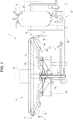
- the sleeve 19 is connected to the plunger 40 by means of two rigid axial bars 45, which are located on the outside of the tubular body 11 on diametrally opposite sides, as partially illustrated in Figure 2 .
- each bar 45 is connected, at an axial end thereof, to a stem 46 axially projecting from the plunger 40 and, at the opposite axial end, to an annular plate 47 fixed to the sleeve 19.
- the force acting on the bottom surface 44 decreases progressively, and the plunger 40 can slide within the compartment 39 downwards, as a result of the force acting on the top surface 43, generated by the gas under pressure constantly present in the top chamber 41. Consequently, the sleeve 19, connected to the plunger 40 via the bars 45, slides within the seat 20 towards the sealing position.
- the sealing surface 21a of the annular gasket 21 can in this way co-operate with the edge 9 of the respective receptacle 2.
- the gas hence exerts on the working surface 48 of the annular gasket 21 a force in the direction of the compartment 39, which is thus transmitted to the sleeve 19; this force is all the higher, the greater the extension of the working surface 48 itself and, hence, the greater the diameter of the opening 9a of the receptacle 2.
- the sleeve 19 will have to oppose a different force (stronger as the diameter of the openings 9a increases) to reach the sealing position and co-operate in a fluid-tight manner with the respective edge 9 of the aforesaid receptacles 2.
- the foregoing can be obtained by filling the top chamber 41, prior to the filling operation, with a gas at a pressure value P1 higher than the pressure value P0, proportional to the diameter of the opening 9a of the respective receptacle 2. There will thus be a force of greater intensity generated by the new gas under pressure on the top surface 43 of the plunger 40 and transmitted, by means of the bars 45, to the sleeve 19, that will be able to oppose the aforesaid force generated by the pressurising gas and applied to the working surface 48 delimited on the annular gasket 21.
- each filling device 4 further comprises a cam-follower roller 50, which is mounted on the stem 46 of the plunger 40, preferably by means of a bar 49 radially projecting from the latter, and co-operates, in use, with a fixed cam 51, mounted on the carousel 3 and extending circumferentially on the peripheral portion 3a through a certain angle about the axis A.
- a cam-follower roller 50 which is mounted on the stem 46 of the plunger 40, preferably by means of a bar 49 radially projecting from the latter, and co-operates, in use, with a fixed cam 51, mounted on the carousel 3 and extending circumferentially on the peripheral portion 3a through a certain angle about the axis A.
- the roller 50 is configured for co-operating with the cam 51 in order to ensure a gradual downward displacement of the plunger 40 within the compartment 39 and, consequently, of the sleeve 19 from the release position towards the sealing position.
- the cam 51 has ( Figures 5 and 6):
- each roller 50 co-operates only with the attack portion 54 in order to ensure a gradual descent of the respective plunger 40 when this slides axially downwards within the respective compartment 39 following upon exit of the gas under pressure from the bottom chamber 42.
- the sleeve 19 can slide gradually from the release position towards the sealing position, and the annular gasket 21 can come into contact with the edge 9 of the respective receptacle 2 delicately, preventing sharp displacements that could cause crushing of the body 7 of the receptacle 2 itself.
- each roller 50 does not co-operate in contact with the release portion 52 and the central portion 53 and, hence, the upward end-of-travel position of the roller 50 and the release position of the sleeve 19 are designed so that there will be a certain non-zero distance between the roller 50 itself and the release portion 52 and the central portion 53 of the cam 51.
- the aforesaid release portion 52 and central portion 53 of the cam 51 basically perform a safety function: they are configured to move the roller 50, and hence the plunger 40 and the sleeve 19, upwards in the case in which these remain blocked downwards in the event of anomalous operating conditions. In the latter case, the roller 50, and hence the plunger 40 and the sleeve 19, do not reach the respective upward end-of-travel position (for example, the release position for the sleeve 19).
- the release portion 52 presents a slight slope and a length greater than the slope and the length of the attack portion 54, in order to guide the roller 50 to perform the displacement upwards, preventing any sharp movements that might cause impact.
- the more accentuated slope and smaller length of the attack portion 54 as compared to those of the release portion 52 derive from the need for rapidly providing a support for the receptacle 2 to be filled, once it has entered the carousel 3 via the input starwheel.
- Figures 4a to 4c illustrate the operation of the filling machine 1 during three successive operating conditions.
- the receptacle 2 to be filled is fed by the carousel 3 in a lower position with respect to the filling device 4 and is positioned so as to be set with the edge 9 of the body 7 bearing upon the annular gasket 21 of the tubular body 11.
- the plunger 40 controls, by causing exit of the gas under pressure from the bottom chamber 42, displacement of the sleeve 19 from the release position to the sealing position. This displacement occurs gradually thanks to the interaction of the roller 50 with the attack portion 54 of the cam 51.
- the valve 35 is opened to start the pressurising step: the gas under pressure contained in the chamber 34 flows along the pressurising/discharging circuit 31, into the receptacle 2, until the pressure inside the latter reaches the value of the pressure of the tank 5 that contains the pourable product to be poured into the receptacle 2 itself.
- the shutter 13 is displaced, via the actuator 30, from the closed position to the open position.
- the pourable product can hence flow into the channel 12, through the outlet opening 18 and, then, into the receptacle 2.
- the gas contained in the receptacle 2 is expelled via the pressurising/discharging circuit 31.
- valve 38 is opened to start the decompression step: the receptacle 2 is depressurized by causing the gas contained in the top part of the body 7 to flow out along the decompression circuit 32, towards the chamber 37.
- the plunger 40 controls, by filling the bottom chamber 42 with the gas under pressure, displacement of the sleeve 19 from the sealing position to the release position ( Figure 3 ).
- filling of the bottom chamber 42 occurs before the roller 50 reaches the release portion 52 of the cam 51, so as to prevent, in normal operating conditions, any undesirable contact of the roller 50 with the aforesaid portion 52.
- the full receptacle 2 is conveyed towards the output starwheel, and a new empty receptacle 2 is positioned underneath the filling valve 8.
- the roller 50 In the case where anomalous operating conditions were to arise, on account of which the plunger 40 and, hence, the sleeve 19 were to remain blocked downwards, the roller 50 would come into contact with the release portion 52, which would determine an upward movement of the roller 50 itself. Consequently, the sleeve 19 would be displaced upwards as far as an intermediate position between the release position and the sealing position. At this point, the roller would co-operate with the central portion 53, and the receptacle 2, forcibly separated from the annular gasket 21, would be conveyed towards the output starwheel, and the filling machine 1 would be stopped in order to check for possible problems.
- the filling device 4 makes it possible to handle receptacles 2 of different formats and/or dimensions without any need to replace the elastic means acting on the sleeve 19.
- the opening 9a of the receptacle 2 could have a non-circular shape, for example elliptical, and, hence, the elastic stiffness of the gas spring 56 could be selectively modified according to the dimensions of the opening 9a itself.
Landscapes
- Filling Of Jars Or Cans And Processes For Cleaning And Sealing Jars (AREA)
Applications Claiming Priority (1)
| Application Number | Priority Date | Filing Date | Title |
|---|---|---|---|
| IT201700138400 | 2017-11-30 |
Publications (1)
| Publication Number | Publication Date |
|---|---|
| EP3498657A1 true EP3498657A1 (fr) | 2019-06-19 |
Family
ID=61527468
Family Applications (1)
| Application Number | Title | Priority Date | Filing Date |
|---|---|---|---|
| EP18207298.3A Withdrawn EP3498657A1 (fr) | 2017-11-30 | 2018-11-20 | Dispositif pour remplir des récipients avec un produit liquide sous pression |
Country Status (1)
| Country | Link |
|---|---|
| EP (1) | EP3498657A1 (fr) |
Citations (4)
| Publication number | Priority date | Publication date | Assignee | Title |
|---|---|---|---|---|
| US4674547A (en) * | 1984-10-02 | 1987-06-23 | Andriano Simonazzi | Container filling apparatus with adjustable pressure sealing means |
| WO1994010079A1 (fr) * | 1992-10-30 | 1994-05-11 | Simonazzi S.P.A. | Procede pour remplir des recipients avec des liquides, en particulier des canettes, et systeme de valve de remplissage pour mettre en oeuvre le procede |
| JP2002370797A (ja) * | 2001-06-12 | 2002-12-24 | Shibuya Kogyo Co Ltd | 充填バルブ |
| DE102008011109A1 (de) * | 2008-02-26 | 2009-09-03 | Khs Ag | Füllelement zum Füllen von Behältern mit einem flüssigen Füllgut, sowie Füllmaschine |
-
2018
- 2018-11-20 EP EP18207298.3A patent/EP3498657A1/fr not_active Withdrawn
Patent Citations (4)
| Publication number | Priority date | Publication date | Assignee | Title |
|---|---|---|---|---|
| US4674547A (en) * | 1984-10-02 | 1987-06-23 | Andriano Simonazzi | Container filling apparatus with adjustable pressure sealing means |
| WO1994010079A1 (fr) * | 1992-10-30 | 1994-05-11 | Simonazzi S.P.A. | Procede pour remplir des recipients avec des liquides, en particulier des canettes, et systeme de valve de remplissage pour mettre en oeuvre le procede |
| JP2002370797A (ja) * | 2001-06-12 | 2002-12-24 | Shibuya Kogyo Co Ltd | 充填バルブ |
| DE102008011109A1 (de) * | 2008-02-26 | 2009-09-03 | Khs Ag | Füllelement zum Füllen von Behältern mit einem flüssigen Füllgut, sowie Füllmaschine |
Similar Documents
| Publication | Publication Date | Title |
|---|---|---|
| EP1995208B2 (fr) | Machine rotative de remplissage pour le remplissage de récipients avec du liquide | |
| EP2871150B1 (fr) | Unité et procédé de remplissage d'un article avec un produit liquide | |
| US10040582B2 (en) | Filling devices for isobaric filling machines for filling bottles with alimentary liquids | |
| US9010381B2 (en) | Filling system | |
| US8955560B2 (en) | Method for the pressursed filling of bottles or like containers, and filling system and filling machine for carrying out said method | |
| SE466194B (sv) | Fyllningsventiler foer burkar och liknande behaallare | |
| US20160023877A1 (en) | Filling devices for filling machines for level filling of bottles and filling machines containing such devices | |
| EP3177539B1 (fr) | Unité et procédé de remplissage de contenants formant des capsules à usage unique pour l'extraction ou l'infusion de boissons | |
| EP3105169B1 (fr) | Procédé et système de remplissage de récipients | |
| EP3498658B1 (fr) | Machine de remplissage de récipients avec un produit coulant sous pression | |
| EP3498657A1 (fr) | Dispositif pour remplir des récipients avec un produit liquide sous pression | |
| US9004904B2 (en) | Apparatus for moulding plastic preforms | |
| EP3572372B1 (fr) | Buse de remplissage pour machines de remplissage, en particulier pour machines de remplissage pondérales, de récipients tels que des fûts, des bouteilles, des boîtes de conserve et/ou similaires | |
| US6520221B2 (en) | Filling nozzle with interception of supply liquids for filling machines | |
| EP3206960B1 (fr) | Dispositif et procédé pour alimenter et doser des sachets filtres avec des produits pour infusion ou extraction | |
| EP3421411B1 (fr) | Unité de remplissage d'un article avec un produit versable | |
| EP1457457A2 (fr) | Tête de remplissage | |
| EP3473589A1 (fr) | Machine de remplissage et procédé de remplissage pour remplir des contenants avec un produit liquide sous pression | |
| EP2949617B1 (fr) | Unité et procédé de remplissage à contact ou sans contact d'un article avec un produit liquide | |
| US8863789B2 (en) | Method and filling system for filling containers in a pressurized manner | |
| CN112105561A (zh) | 改进的灌装装置 | |
| EP2548838B1 (fr) | Dispositif pour remplir des récipients et procédé de lavage associé | |
| JP2023530599A (ja) | 自己排出型セパレータ | |
| CN113795456A (zh) | 用于用可倾倒产品填充容器的填充阀 | |
| ITMI20101499A1 (it) | Metodo e macchina per la produzione di caffè espresso |
Legal Events
| Date | Code | Title | Description |
|---|---|---|---|
| PUAI | Public reference made under article 153(3) epc to a published international application that has entered the european phase |
Free format text: ORIGINAL CODE: 0009012 |
|
| STAA | Information on the status of an ep patent application or granted ep patent |
Free format text: STATUS: THE APPLICATION HAS BEEN PUBLISHED |
|
| AK | Designated contracting states |
Kind code of ref document: A1 Designated state(s): AL AT BE BG CH CY CZ DE DK EE ES FI FR GB GR HR HU IE IS IT LI LT LU LV MC MK MT NL NO PL PT RO RS SE SI SK SM TR |
|
| AX | Request for extension of the european patent |
Extension state: BA ME |
|
| STAA | Information on the status of an ep patent application or granted ep patent |
Free format text: STATUS: REQUEST FOR EXAMINATION WAS MADE |
|
| 17P | Request for examination filed |
Effective date: 20191206 |
|
| RBV | Designated contracting states (corrected) |
Designated state(s): AL AT BE BG CH CY CZ DE DK EE ES FI FR GB GR HR HU IE IS IT LI LT LU LV MC MK MT NL NO PL PT RO RS SE SI SK SM TR |
|
| STAA | Information on the status of an ep patent application or granted ep patent |
Free format text: STATUS: THE APPLICATION IS DEEMED TO BE WITHDRAWN |
|
| 18D | Application deemed to be withdrawn |
Effective date: 20210601 |