EP3498632B1 - Automobile transport frame for use in container, and container having same - Google Patents
Automobile transport frame for use in container, and container having same Download PDFInfo
- Publication number
- EP3498632B1 EP3498632B1 EP16912566.3A EP16912566A EP3498632B1 EP 3498632 B1 EP3498632 B1 EP 3498632B1 EP 16912566 A EP16912566 A EP 16912566A EP 3498632 B1 EP3498632 B1 EP 3498632B1
- Authority
- EP
- European Patent Office
- Prior art keywords
- fixing frame
- container
- upright post
- transportation rack
- automobile transportation
- Prior art date
- Legal status (The legal status is an assumption and is not a legal conclusion. Google has not performed a legal analysis and makes no representation as to the accuracy of the status listed.)
- Active
Links
Images


Classifications
-
- B—PERFORMING OPERATIONS; TRANSPORTING
- B65—CONVEYING; PACKING; STORING; HANDLING THIN OR FILAMENTARY MATERIAL
- B65D—CONTAINERS FOR STORAGE OR TRANSPORT OF ARTICLES OR MATERIALS, e.g. BAGS, BARRELS, BOTTLES, BOXES, CANS, CARTONS, CRATES, DRUMS, JARS, TANKS, HOPPERS, FORWARDING CONTAINERS; ACCESSORIES, CLOSURES, OR FITTINGS THEREFOR; PACKAGING ELEMENTS; PACKAGES
- B65D90/00—Component parts, details or accessories for large containers
- B65D90/004—Contents retaining means
- B65D90/006—Contents retaining means fixed on the floor of the container
-
- B—PERFORMING OPERATIONS; TRANSPORTING
- B65—CONVEYING; PACKING; STORING; HANDLING THIN OR FILAMENTARY MATERIAL
- B65D—CONTAINERS FOR STORAGE OR TRANSPORT OF ARTICLES OR MATERIALS, e.g. BAGS, BARRELS, BOTTLES, BOXES, CANS, CARTONS, CRATES, DRUMS, JARS, TANKS, HOPPERS, FORWARDING CONTAINERS; ACCESSORIES, CLOSURES, OR FITTINGS THEREFOR; PACKAGING ELEMENTS; PACKAGES
- B65D85/00—Containers, packaging elements or packages, specially adapted for particular articles or materials
- B65D85/68—Containers, packaging elements or packages, specially adapted for particular articles or materials for machines, engines or vehicles in assembled or dismantled form
-
- B—PERFORMING OPERATIONS; TRANSPORTING
- B65—CONVEYING; PACKING; STORING; HANDLING THIN OR FILAMENTARY MATERIAL
- B65D—CONTAINERS FOR STORAGE OR TRANSPORT OF ARTICLES OR MATERIALS, e.g. BAGS, BARRELS, BOTTLES, BOXES, CANS, CARTONS, CRATES, DRUMS, JARS, TANKS, HOPPERS, FORWARDING CONTAINERS; ACCESSORIES, CLOSURES, OR FITTINGS THEREFOR; PACKAGING ELEMENTS; PACKAGES
- B65D88/00—Large containers
- B65D88/02—Large containers rigid
- B65D88/12—Large containers rigid specially adapted for transport
- B65D88/121—ISO containers
-
- B—PERFORMING OPERATIONS; TRANSPORTING
- B65—CONVEYING; PACKING; STORING; HANDLING THIN OR FILAMENTARY MATERIAL
- B65D—CONTAINERS FOR STORAGE OR TRANSPORT OF ARTICLES OR MATERIALS, e.g. BAGS, BARRELS, BOTTLES, BOXES, CANS, CARTONS, CRATES, DRUMS, JARS, TANKS, HOPPERS, FORWARDING CONTAINERS; ACCESSORIES, CLOSURES, OR FITTINGS THEREFOR; PACKAGING ELEMENTS; PACKAGES
- B65D2585/00—Containers, packaging elements or packages specially adapted for particular articles or materials
- B65D2585/68—Containers, packaging elements or packages specially adapted for particular articles or materials for machines, engines, or vehicles in assembled or dismantled form
- B65D2585/6802—Containers, packaging elements or packages specially adapted for particular articles or materials for machines, engines, or vehicles in assembled or dismantled form specific machines, engines or vehicles
- B65D2585/686—Containers, packaging elements or packages specially adapted for particular articles or materials for machines, engines, or vehicles in assembled or dismantled form specific machines, engines or vehicles vehicles
- B65D2585/6867—Containers, packaging elements or packages specially adapted for particular articles or materials for machines, engines, or vehicles in assembled or dismantled form specific machines, engines or vehicles vehicles automobiles
Definitions
- the present invention generally relates to the field of transportation, and more particularly, to an automobile transportation rack for the container and a container comprising the same.
- Another way is to employ an automobile transportation rack in which a frame construction is adopted so as to retain the automobiles through an upper deck and a lower deck, the top space of the container can be utilized, thus a 40HC container can load three or four automobiles, but such an automobile transportation rack is disadvantageous in that: 1, the transportation rack is complicated in its structure and has a heavier weight and higher fabrication cost; 2, the transportation rack stack after its folding has a large size, thereby a 40HC container can only load a dozen sets of the transportation racks, resulting in a higher recovery cost; 3, the deck structure of the transportation rack would occupy and influence the lower space for the automotives, thus a number of large-size automobiles can not be effectively loaded and transported.
- the prior art DE 20 2015 106050 U1 discloses a frame system for supporting an associated vehicle for transport within an existing transportable structure having longitudinal side structures, the frame system comprising a transverse support frame supported by two vertical uprights, of which one disposed at each end of the support frame, each post being provided with attachment means for securing the top and bottom of the post at a plurality of locations along the length of the associated side structure, the support frame having a vehicle loaded thereon or, without such a vehicle, being liftable and, once powered up, attachable to the post at a selected location for transport within the transportable structure, each end of the support frame having an end plate, which has an inwardly facing surface on the adjacent one up and down the vertical post when raised and lowered, characterized in that at least one of the end plates has a telescopic connection with the rest of the support frame such that the effective length of the support frame between the posts (140) can be changed so that the frame system can be used in existing transportable structures with different lateral spacing between the side structures.
- a vehicle support for a container , comprises a frame, suspended from one or more elements, of adjustable span, to vary frame disposition, [such as elevation and/or tilt], from an (un)loading to a transport mode; the frame is configured for converting or adapting a standard container, and a self-contained retractable version incorporated in a demountable container extension module is envisaged.
- US 4 963 067 A discloses a system for loading and transporting wheeled vehicles on a transporting vehicle, such as a ship or rail car, comprises supporting a plurality of wheeled vehicles on each of a plurality of frames in vertically-spaced relation to each other and then inserting the respective frames and their supported vehicles matingly into respective enclosures.
- the enclosures, with their frames and vehicles inside, are loaded onto the transporting vehicle by compactly stacking the enclosures one atop the other in weather-exposed positions, the enclosures nevertheless serving to protect the vehicles from external hazards.
- the apparatus further comprises at least one rail means providing a track for said wheel support means and a positioning means for enabling said rail means to be positioned in substantially aligned adjoining relationship with like rail means of the container.
- the motor vehicles can be moved into or out of the container supported on two-wheel support means which run on aligned two-rail tracks without an operative having to enter the vehicle particularly whilst the vehicle is inside the container.
- a winch or other control means can be provided for pulling the vehicle into and out of the container.
- the apparatus includes a lift and a loading/unloading ramp and is mounted on the back of a trailer carrying an inter modal container loaded with the vehicles.
- the pallets have wheels for moving within the rails and are selectively lockable within the container.
- one aspect according to the present invention provides an automobile transportation rack according to claim 1.
- the upright posts comprise a first upright post and a second upright post, the first upright post is telescopically nested in the second upright post, the length of either one of the first and second upright posts being less than the internal width of the container.
- the top coupling portion is located at the top end of the first upright post, the bottom coupling portion is located at the bottom end of the second upright post.
- the top coupling portion and the bottom coupling portion each has a profile plate of a shape identical to that of the corrugation of the side walls.
- the top coupling portion is provided with a wire loop for connecting with a vehicle moving apparatus.
- the connecting portion is a shaft sleeve provided on the second upright post and movable vertically with respect to the second upright post
- the shaft sleeve comprises a shaft sleeve body nested on the second upright post and a protrusion protruding in the radial direction of the shaft sleeve body.
- location holes are disposed on the second upright post, and the shaft sleeve is secured to the second upright post with pin shafts passing through the location holes.
- the front wheel fixing frame and the rear wheel fixing frame each comprise a first transversal beam and a second transversal beam which form a recess, and connecting beams connecting the first transversal beam and the second transversal beam, the connecting beam is provided with a mating part for cooperating with the connecting portion thereon.
- the mating part is a slider with a hole
- the slider is provided on the connecting beam and movable with respect to the connecting beam in a direction perpendicular to the first transversal beam and the second transversal beam.
- a retainer for retaining the slider is disposed on the connecting beam.
- the top coupling portion has an upward opening
- the transversal support bar has a connector for extending into the opening.
- the transversal support bar comprises a length adjustment mechanism for adjusting the length of the transversal support bar.
- the transversal support bar comprises a first bar and a second bar
- the length adjustment mechanism is a right-left-handed screw connected between the first bar and the second bar.
- it further comprises a bottom tire fixing frame connected to the pair of upright posts by stop pins for preventing movement of the lower vehicle, the bottom tire fixing frame being configured as an integral fixing frame or a separable fixing frame.
- the integral fixing frame comprises a first bracket and a second bracket provided along the longitudinal direction of the vehicle, and a tire retainer bracket located between the first bracket and the second bracket.
- Another aspect of the present invention provides a container according to claim 14.
- the automobile transportation rack for the container according to the present invention is simple in its structure and has a light weight, and each of the two pairs of the upright posts, the transversal support bar, the front wheel fixing frame and the rear wheel fixing frame are detachably assembled to each other. Hence, individual components after being disassembled are easy to be transported and stored, thus it is possible to take full advantage of the internal width of the container to increase the number of the cargos to be shipped.
- front wheel transportation rack 2 rear wheel transportation rack 10: upright post 11: first upright post 12: second upright post 121: location hole 13: shaft sleeve 131: shaft sleeve body 132: protrusion 14: top coupling portion 141: top profile plate 142: circular hole 143: wire loop 144: top channel steel 15: bottom coupling portion 151: bottom profile plate 152: bottom channel steel 20: rear wheel fixing frame 21a: first transversal beam of the rear wheel fixing frame 21b: second transversal beam of the rear wheel fixing frame 22: connecting beam of the rear wheel fixing frame 23: through hole 30: front wheel fixing frame 31a: first transversal beam of the front wheel fixing frame 31b: second transversal beam of the front wheel fixing frame 32: connecting beam of the front wheel fixing frame 33: slider 331: slider hole 34: retainer hole 35: retainer pin shaft 40: transversal support bar 41: first bar 411: first bar connector 42: second bar 421: second bar connector 43: right-left-handed screw 50: bottom tire fixing frame 51a
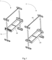
- an automobile transportation rack for the container the container 100 comprises side walls, a bottom plate and a top plate.
- the automobile transportation rack for the container comprises two pairs of upright posts 10, transversal support bars 40, a front wheel fixing frame 30 and a rear wheel fixing frame 20.
- a pair of upright posts 10, a transversal support bar 40 and a front wheel fixing frame 30 can be assembled as a front wheel transportation rack 1 for carrying the front wheel of a vehicle; and the other pair of the upright posts 10, another transversal support bar 40 and a rear wheel transportation rack 2 can be assembled as a rear wheel transportation rack 2 for carrying the rear wheel of the vehicle.
- each upright post 10 has a connecting portion for connecting with the front wheel fixing frame 30 or the rear wheel fixing frame 20.
- the transversal support bar 40 is adjustably connected between the tops of a pair of upright posts 10 to enable the upright posts 10 to abut against the side walls.
- the front wheel fixing frame is connected between a pair of upright posts 10 and movable vertically with respect to the upright posts 10 through the connecting portions on the pair of upright posts 10.
- the rear wheel fixing frame 20 is connected between the other pair of upright posts 10, and is movable vertically with respect to the upright posts 10 through the connecting portions located on the other pair of upright posts 10.
- each of the two pairs of the upright posts 10, the transversal support bar 40, the front wheel fixing frame 30 and the rear wheel fixing frame 20 are detachably assembled to each other.
- the automobile transportation rack for the container according to the present invention is simple in its structure and has a light weight, and each of the two pairs of the upright posts, the transversal support bar, the front wheel fixing frame and the rear wheel fixing frame are detachably assembled to each other. Hence, individual components after being disassembled are easy to be transported and stored, and it is possible to take full advantage of the internal width of the container to increase the number of the cargos to be shipped.
- each 40'HC container 100 can carry 60-80 sets of automobile transportation racks for the container.
- the upright post 10 comprises a top coupling portion 14 at the top thereof and a bottom coupling portion 15 at the bottom thereof.
- the transversal support bar 40 connects the top coupling portions 14 of a pair of the upright posts 10, and the bottom coupling portion 15 is used for connecting with the bottom plate.
- the upright posts 10 comprises a first upright post 11 and a second upright post 12, and the first upright post 11 is telescopically nested in the second upright post 12.
- the length of either one of the first upright post 11 and the second upright post 12 is less than the internal width of the container 100, which facilitates the control of the packing size and improves the packing rate of the container 100 at the time of the recovery of the transportation rack.
- the connecting portion is a shaft sleeve 13 provided on the second upright post 12 and movable vertically with respect to the second upright post 12, and the shaft sleeve 13 comprises a shaft sleeve body 131 nested on the second upright post 12 and a protrusion 132 protruding in the radial direction of the shaft sleeve body 131.
- a row of location holes 121 are disposed on the second upright post 12 for varying the location of the shaft sleeve 13 (the connecting portion) and thus varying the height of the front (rear) wheel fixing frame connected onto the upright posts 10. That is to say, the location holes 121 could be disposed on the second upright post 12, and the shaft sleeve 13 is secured with the second upright post 12 by a pin shaft passing through the location hole 121.
- top coupling portion 14 is located at the top end of the first upright post 11, and the bottom coupling portion 15 is located at the bottom end of the second upright post 12. Furthermore, the top coupling portion 14 and the bottom coupling portion 15 each have a profile plate of a shape identical to that of the corrugation of the side walls.
- the top coupling portion 14 may comprise a top channel steel 144 and a top profile plate 141 connected with the top channel steel 144.
- the top profile plate 141 is connectable with and the top channel steel 144 using a fastening bolt, and the top channel steel 144 is soldered to the first upright post 11.
- the top profile plate 141 With adjusting the location of the top profile plate 141 in the container, it is possible to roughly adjust the location of the first upright post 11 (the upright post 10), while with adjusting the position between the top profile plate 141 and the top channel steel 144 (using a bolt), it is possible to finely adjust the location of the upright post 10.
- the top profile plate 141 provided at the top of the first upright post 11 can be used to effectively limit the position of the upright post 10.
- top profile plate 141 can also be provided with notches thereon to prevent interference with the wire loop (not shown) of the standard container.
- top coupling portion 14 is also provided with wire loops 143 at the top channel steel 144 to connect with a manual chain hoist (as an example of the vehicle moving apparatus).
- the bottom coupling portion 15 can comprise a bottom channel steel 152 and a bottom profile plate 151 coupled with the bottom channel steel 152.
- the bottom channel steel 152 is reserved with self-tapping holes for connecting with the container floor.
- the automobile transportation rack for the container of the present invention realizes the joining of the profile plate, which has a shape approximately identical to that of the corrugated plate of the container 100, with the upright posts 10.
- the profile plate connected with the upright post 10, it is possible to adjust the location of the upright post 10 in the container 100 so as to carry vehicles of different dimensions.
- the shape of the profile plate is approximately identical to that of the side plates of the container 100 such that the location of the upright posts 10 can be restricted in a simple and effective way.
- the profile plate is connected with the upright post 10 using a bolt so that the relative position therebetween can be finely adjusted.
- the upright post 10 is secured onto the bottom plate of the container 100 by means of screws (self-tapping screws).
- the four upright posts 10 of a set of the automobile transportation rack for the container are identical in their structures, thus the upright posts are universal and interchangeable.
- the front wheel fixing frame 30 and the rear wheel fixing frame 20 will be descried referring to Figures 3 and 4 .
- the rear wheel fixing frame 20 comprises a first transversal beam 21a of the rear wheel fixing frame and a second transversal beam 21b of the rear wheel fixing frame which form a recess, and a connecting beam 22 of the rear wheel fixing frame for connecting the first transversal beam 21a of the rear wheel fixing frame and the second transversal beam 21b of the rear wheel fixing frame.
- the connecting beam 22 of the rear wheel fixing frame is provided with a mating part for cooperating with the shaft sleeve.
- the mating part of the rear wheel fixing frame 20 is a through hole 23.
- the front wheel fixing frame 30 comprises a first transversal beam 31a of the front wheel fixing frame and a second transversal beam 31b of the front wheel fixing frame which form a recess, and a connecting beam 32 of the front wheel fixing frame for connecting the first and second transversal beams 31a, 31b of the front wheel fixing frame
- the connecting beam 32 of the front wheel fixing frame is provided with a mating part for cooperating with the shaft sleeve.
- the front wheel fixing frame 30 its mating part is a slider 33 having a slider hole 331 therein, and the slider 33 is provided onto the connecting beam 32 of the front wheel fixing frame and movable with respect to the connecting beam 32 of the front wheel fixing frame in a direction perpendicular to the first and second transversal beams 31a, 31b of the front wheel fixing frame. Further, the connecting beam 32 of the front wheel fixing frame is provided with a retainer for retaining the slider 33 thereon.
- the connecting beam 32 of the front wheel fixing frame is made of C-form steel
- the slider 33 is slidable in the C-form steel
- the top flange plate of the C-form steel is provided with a retainer hole 34 through which the retainer pin shaft 35 can extend to stop the sliding of the slider 33.
- the top coupling portion 14 has an upward opening (a circular hole 142), and the transversal support bar 40 has a connector for extending into the opening, for example, the connector can be tapered.
- the transversal support bar 40 comprises a length adjustment mechanism for adjusting the length of the transversal support bar 40.
- the transversal support bar 40 comprises first and second bars 41, 42, and the length adjustment mechanism is a right-left-handed screw 43 connected between the first and second bars 41, 42.
- the connector which is used for extending into the top coupling portion 14 so as to connect with the top coupling portion 14, is a first bar connector 411 provided on the first bar 41 and a second bar connector 421 provided on the second bar 42.
- the tapered connector (i.e., the first and second bar connectors 411, 421) of the transversal support bar 40 extends into the upright post 10, and the length of the transversal support bar 40 in the width direction of the container is lengthened with the right-left-handed screw 43, so that the profile plate of the upright post 10 abuts closed against the side plate of the container 100, thus the upright post 10 in the transverse and longitudinal directions is supported effectively.
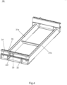
- the automobile transportation rack for the container further comprises a bottom tire fixing frame 50 connected to the pair of upright posts 10 by stop pins for preventing movement of the lower vehicles.
- the bottom tire fixing frame 50 is configured as an integral fixing frame or a separable fixing frame.
- the bottom tire fixing frame 50 can be connected with the upright post 10 using stop pins in such a way that the relative position therebetween can be adjusted to accommodate the cars with different wheel tracks.
- the integral fixing frame comprises a first bracket 51a and a second bracket 51b provided along the longitudinal direction of the vehicle, and a tire retainer bracket located between the first and second brackets 51a, 51b.
- the tire retainer bracket may comprise a tire retainer bracket connector 52 for connected with the first bracket 51a or the second bracket 51b, two tire stoppers 53 for preventing the movement of the tire, and a connecting beam 54 connected between the two tire stoppers 53.
- first and second brackets 51a, 51b are arranged in parallel, and the tire retainer bracket is movable with respect to the first and second brackets 51a, 51b, and the first and second brackets 51a, 51b may be connected with the aforesaid bottom channel steel 152 of the bottom coupling portion 15, thereby the bottoms of a pair of upright posts 10 arranged in the left-right-direction can be connected as a whole, thus creating a bottom support.
- the separable tire fixing frame 60 as shown in Figure 7 can be used in combination with the integral fixing frame as shown in Figure 6 .
- the separable tire fixing frame 60 can also be used solely to fix the lower vehicles positioned on the bottom surface of the container 100.
- the first upright post 11 is firstly nested into the second upright post 12, and the relative position between the channel steel of the second upright post 12 at the lower end and the profile plate is adjusted in accordance with a preset position, and then the two are connected using a fastening bolt.
- the two pairs of upright posts 10 in a bilateral symmetry are placed into the container 100 in accordance with preset positions, so that the profile plate of each of the upright posts 10 abuts against the side plate of the container 100.
- the front wheel fixing frame 30 and the rear wheel fixing frame 20 are respectively connected with the shaft sleeve 13 of the upright post 10.
- the tapered connector i.e., the first and second bar connectors 411, 421
- the first and second bar connectors 411, 421 of the transversal support bar 40 is inserted into the top of the first upright posts 11 of the left and right upright posts 10 arranged opposite to each other and then the first upright post 11 is lifted up to a preset position, then the first upright post 11 and the second upright post 12 are locked using a retainer pin, and a right-left-handed screw 43 is adjusted so as to cause the transversal support bar 40 to abut closely against the upright posts 10.
- the assemble of the automobile transportation rack for the container according to the present invention has been completed.
- the first automobile 201 is driven into the fore wheel transportation frame 1 and the rear wheel transportation frame 2 and parked there, reverses from the end door 101 of the container 100 into the container 100, and the front wheels and rear wheels of the first automobile 201 are respectively carried on the front wheel fixing frame 30 and the rear wheel fixing frame 40.
- the front wheel fixing frame 30 and the rear wheel fixing frame 40 which carry the first automobile 201, are lifted to a preset height with the manual chain, and the front wheels and the front wheel fixing frame 30 as well as the rear wheels and the rear wheel fixing frame 40 could be secured with fasteners, such as a binding tape.
- the height of the front wheel fixing frame 30 is raised higher than the height at which the rear wheel fixing frame 40 is lifted, this is because the heavier components, such as the engine and the transmission, of a conventional vehicle are located at the front of the vehicle, so that the center of gravity of the vehicle is at the front, if the front wheel is lower than the rear wheel, then the acceleration or deceleration in the driving could cause the vehicle, as the inertia effect, to incline and dash downward out of the automobile transportation rack for the container in forward direction, that is, toward the direction of the front wheel,.
- the rear wheel fixing frame 40 rotates around the shaft sleeve connected thereto with respect to the upright post 10 in the lifting process, and the front wheel fixing frame 30 also rotates around the shaft sleeve connected thereto with respect to the upright post 10.
- the front wheel fixing frame 30 moves close to the rear wheel fixing frame 40, that is, in the illustrated embodiments, the slider hole 331 of the front wheel fixing frame 30 is connected to the protrusion of the shaft sleeve and is fixed with respect to the upright post 10, and the front wheel fixing frame 30 moves close to the rear wheel fixing frame 40 with respect to the slider 33.
- the retainer pin can be attached so as to prevent the slider 33 from continuing sliding.
- the bottom tire fixing frame is connected to the upright post 10, and the second automobile 202 is driven into a preset position, then the second automobile 202 is fastened using a fastener, such as a conventional retaining band, thus completing the loading of the two automobiles.
- a fastener such as a conventional retaining band
- the foregoing operations may be repeated for the following two vehicles, then loading of the 40HC container 100 could be completed with a total of four automobiles including the third and fourth automobiles 203, 204.
- the entire operation process does not require forklifts, and two to four personals are sufficient to perform the process.
- a container 100 comprising the above mentioned automobile transportation rack for the container.
- one 40HC container 100 may comprise two sets of automobile transportation rack for the container for loading four automobiles, or comprise one set of automobile transportation rack for the container for loading three large-sized automobiles.
- the respective locations of the profile plate, the upright post 10, the fore wheel transportation frame 1 and the rear wheel transportation frame 2 may be calculated in advance according to the type of the vehicles before loading the same.
Landscapes
- Engineering & Computer Science (AREA)
- Mechanical Engineering (AREA)
- Pallets (AREA)
- Handcart (AREA)
Description
- The present invention generally relates to the field of transportation, and more particularly, to an automobile transportation rack for the container and a container comprising the same.
- With the development of the automobile industry, automobile transportation is usually performed using special vehicles for automobile transportation or containers. One way for the container to transport the automobiles is to fix the automobiles onto the container floor directly by means of wooden wedges, screws or retaining bands, however, by this way, the automobiles can only be laid flat on the container floor, the container space can not be effectively used, making that a 40HC container can only load two automobiles. Another way is to employ an automobile transportation rack in which a frame construction is adopted so as to retain the automobiles through an upper deck and a lower deck, the top space of the container can be utilized, thus a 40HC container can load three or four automobiles, but such an automobile transportation rack is disadvantageous in that: 1, the transportation rack is complicated in its structure and has a heavier weight and higher fabrication cost; 2, the transportation rack stack after its folding has a large size, thereby a 40HC container can only load a dozen sets of the transportation racks, resulting in a higher recovery cost; 3, the deck structure of the transportation rack would occupy and influence the lower space for the automotives, thus a number of large-size automobiles can not be effectively loaded and transported.
- The
prior art DE 20 2015 106050 U1 discloses a frame system for supporting an associated vehicle for transport within an existing transportable structure having longitudinal side structures, the frame system comprising a transverse support frame supported by two vertical uprights, of which one disposed at each end of the support frame, each post being provided with attachment means for securing the top and bottom of the post at a plurality of locations along the length of the associated side structure, the support frame having a vehicle loaded thereon or, without such a vehicle, being liftable and, once powered up, attachable to the post at a selected location for transport within the transportable structure, each end of the support frame having an end plate, which has an inwardly facing surface on the adjacent one up and down the vertical post when raised and lowered, characterized in that at least one of the end plates has a telescopic connection with the rest of the support frame such that the effective length of the support frame between the posts (140) can be changed so that the frame system can be used in existing transportable structures with different lateral spacing between the side structures. - The prior art
WO 02/28748 A1 - The prior art
US 4 963 067 A discloses a system for loading and transporting wheeled vehicles on a transporting vehicle, such as a ship or rail car, comprises supporting a plurality of wheeled vehicles on each of a plurality of frames in vertically-spaced relation to each other and then inserting the respective frames and their supported vehicles matingly into respective enclosures. The enclosures, with their frames and vehicles inside, are loaded onto the transporting vehicle by compactly stacking the enclosures one atop the other in weather-exposed positions, the enclosures nevertheless serving to protect the vehicles from external hazards. - The
prior art GB 2 298 842 A - The invention is set out in the appended set of claims.
- To solve the above technical matters, one aspect according to the present invention provides an automobile transportation rack according to
claim 1. - Preferably, the upright posts comprise a first upright post and a second upright post, the first upright post is telescopically nested in the second upright post, the length of either one of the first and second upright posts being less than the internal width of the container.
- Preferably, the top coupling portion is located at the top end of the first upright post, the bottom coupling portion is located at the bottom end of the second upright post.
- According to the invention, the top coupling portion and the bottom coupling portion each has a profile plate of a shape identical to that of the corrugation of the side walls.
- Preferably, the top coupling portion is provided with a wire loop for connecting with a vehicle moving apparatus.
- Preferably, the connecting portion is a shaft sleeve provided on the second upright post and movable vertically with respect to the second upright post, the shaft sleeve comprises a shaft sleeve body nested on the second upright post and a protrusion protruding in the radial direction of the shaft sleeve body.
- Preferably, location holes are disposed on the second upright post, and the shaft sleeve is secured to the second upright post with pin shafts passing through the location holes.
- Preferably, the front wheel fixing frame and the rear wheel fixing frame each comprise a first transversal beam and a second transversal beam which form a recess, and connecting beams connecting the first transversal beam and the second transversal beam, the connecting beam is provided with a mating part for cooperating with the connecting portion thereon.
- Preferably, the mating part is a slider with a hole, and the slider is provided on the connecting beam and movable with respect to the connecting beam in a direction perpendicular to the first transversal beam and the second transversal beam.
- Preferably, a retainer for retaining the slider is disposed on the connecting beam.
- Preferably, the top coupling portion has an upward opening, the transversal support bar has a connector for extending into the opening.
- Preferably, the transversal support bar comprises a length adjustment mechanism for adjusting the length of the transversal support bar.
- Preferably, the transversal support bar comprises a first bar and a second bar, the length adjustment mechanism is a right-left-handed screw connected between the first bar and the second bar.
- Preferably, it further comprises a bottom tire fixing frame connected to the pair of upright posts by stop pins for preventing movement of the lower vehicle, the bottom tire fixing frame being configured as an integral fixing frame or a separable fixing frame.
- Preferably, the integral fixing frame comprises a first bracket and a second bracket provided along the longitudinal direction of the vehicle, and a tire retainer bracket located between the first bracket and the second bracket.
- Another aspect of the present invention provides a container according to
claim 14. - The automobile transportation rack for the container according to the present invention is simple in its structure and has a light weight, and each of the two pairs of the upright posts, the transversal support bar, the front wheel fixing frame and the rear wheel fixing frame are detachably assembled to each other. Hence, individual components after being disassembled are easy to be transported and stored, thus it is possible to take full advantage of the internal width of the container to increase the number of the cargos to be shipped.
- In order that the advantages of the present invention may be more readily understood, the present invention as described above briefly will be described in more detail while referring the specific embodiments illustrated in the drawings. It is to be understood that these drawings depict only typical embodiments of the invention, thus should not be considered as limiting the protective scope of the invention, the invention is described and illustrated with additional characteristics and details by means of the drawings. In the drawings:
-
Figure 1 is a perspective view of an automobile transportation rack for the container according to the present invention; -
Figure 2 is a perspective view of the upright posts of the automobile transportation rack for the container illustrated inFigure 1 ; -
Figure 3 is a perspective view of the rear wheel fixing frame of the automobile transportation rack for the container illustrated inFigure 1 ; -
Figure 4 is a perspective view of the front wheel fixing frame of the automobile transportation rack for the container illustrated inFigure 1 ; -
Figure 5 is a perspective view of the transversal support bar of the automobile transportation rack for the container illustrated inFigure 1 ; -
Figure 6 is a perspective view of the tire retainer bracket for the lower vehicles in one type of the automobile transportation rack for the container according to the present invention; -
Figure 7 is a perspective view of the tire retainer bracket for the lower vehicles in another type of the automobile transportation rack for the container according to the present invention; -
Figure 8 is a perspective view showing a container equipped with the automobile transportation rack for the container illustrated inFigure 1 ; -
Figure 9 is a perspective view showing the vehicle carried by the container illustrated inFigure 8 , in which a first vehicle is loaded onto the automobile transportation rack for the container; -
Figure 10 is a perspective view of the vehicle carried by the container illustrated inFigure 9 , in which the first vehicle is loaded onto the automobile transportation rack for the container while the front wheel fixing frame and the rear wheel fixing frame being lifted; -
Figure 11 is a perspective view of the vehicle carried by the container illustrated inFigure 10 , in which the first vehicle and a second vehicle are loaded onto the automobile transportation rack for the container while the second vehicle being located below the first vehicle; -
Figure 12 is a perspective view of the vehicle carried by the container illustrated inFigure 11 , in which the first vehicle, the second vehicle, the third vehicle and the fourth vehicle are loaded onto the automobile transportation rack for the container while the second vehicle being located below the first vehicle and the fourth vehicle being located below the first vehicle; and -
Figure 13 is a perspective view showing the storage status of the automobile transportation rack for the container after being disassembled. -
1: front wheel transportation rack 2: rear wheel transportation rack 10: upright post 11: first upright post 12: second upright post 121: location hole 13: shaft sleeve 131: shaft sleeve body 132: protrusion 14: top coupling portion 141: top profile plate 142: circular hole 143: wire loop 144: top channel steel 15: bottom coupling portion 151: bottom profile plate 152: bottom channel steel 20: rear wheel fixing frame 21a: first transversal beam of the rear wheel fixing frame 21b: second transversal beam of the rear wheel fixing frame 22: connecting beam of the rear wheel fixing frame 23: through hole 30: front wheel fixing frame 31a: first transversal beam of the front wheel fixing frame 31b: second transversal beam of the front wheel fixing frame 32: connecting beam of the front wheel fixing frame 33: slider 331: slider hole 34: retainer hole 35: retainer pin shaft 40: transversal support bar 41: first bar 411: first bar connector 42: second bar 421: second bar connector 43: right-left-handed screw 50: bottom tire fixing frame 51a: first bracket 51b: second bracket 52: tire retainer bracket connector 53: tire stopper 54: connecting beam 60: separable tire fixing frame 61: tire stopper 100: container 101: end door 201: first vehicle 202: second vehicle 203: third vehicle 204: fourth vehicle - In the following discussion, details are given to provide a more thorough understanding of the present invention. However, those skilled in the art will appreciate that the present invention may be practiced without one or more of these details. In a particular example, some of the technical features known in the art are not described in detail in order to avoid confusion with the present invention. It should be noted that the terms "upper", "lower", "front", "rear", "left", "right" and the like as used herein are for illustrative purposes only and are not intended to be limiting.
- In order to solve the above-described technical problem, according to one aspect of the present invention, there is provided an automobile transportation rack for the container, the
container 100 comprises side walls, a bottom plate and a top plate. The automobile transportation rack for the container comprises two pairs ofupright posts 10,transversal support bars 40, a frontwheel fixing frame 30 and a rearwheel fixing frame 20. As shown inFigure 1 , a pair ofupright posts 10, atransversal support bar 40 and a frontwheel fixing frame 30 can be assembled as a frontwheel transportation rack 1 for carrying the front wheel of a vehicle; and the other pair of theupright posts 10, anothertransversal support bar 40 and a rearwheel transportation rack 2 can be assembled as a rearwheel transportation rack 2 for carrying the rear wheel of the vehicle. - Referring to
Figure 1 , two pairs ofupright posts 10 are used to be provided inside thecontainer 100 and abutting against the side walls and the bottom plate. Eachupright post 10 has a connecting portion for connecting with the frontwheel fixing frame 30 or the rearwheel fixing frame 20. Thetransversal support bar 40 is adjustably connected between the tops of a pair ofupright posts 10 to enable theupright posts 10 to abut against the side walls. The front wheel fixing frame is connected between a pair ofupright posts 10 and movable vertically with respect to theupright posts 10 through the connecting portions on the pair of upright posts 10. The rearwheel fixing frame 20 is connected between the other pair ofupright posts 10, and is movable vertically with respect to theupright posts 10 through the connecting portions located on the other pair of upright posts 10. - Wherein each of the two pairs of the
upright posts 10, thetransversal support bar 40, the frontwheel fixing frame 30 and the rearwheel fixing frame 20 are detachably assembled to each other. - The automobile transportation rack for the container according to the present invention is simple in its structure and has a light weight, and each of the two pairs of the upright posts, the transversal support bar, the front wheel fixing frame and the rear wheel fixing frame are detachably assembled to each other. Hence, individual components after being disassembled are easy to be transported and stored, and it is possible to take full advantage of the internal width of the container to increase the number of the cargos to be shipped.
- As a result, the automobile transportation rack for the container can be disassembled into several separated components, and such disassembled components can enormously save space, and according to different situations, each
40'HC container 100 can carry 60-80 sets of automobile transportation racks for the container. - Turning to
Figure 2 , optionally, theupright post 10 comprises atop coupling portion 14 at the top thereof and abottom coupling portion 15 at the bottom thereof. Thetransversal support bar 40 connects thetop coupling portions 14 of a pair of theupright posts 10, and thebottom coupling portion 15 is used for connecting with the bottom plate. - Furthermore, in the illustrated embodiments, the upright posts 10 comprises a first
upright post 11 and a secondupright post 12, and the firstupright post 11 is telescopically nested in the secondupright post 12. The length of either one of the firstupright post 11 and the secondupright post 12 is less than the internal width of thecontainer 100, which facilitates the control of the packing size and improves the packing rate of thecontainer 100 at the time of the recovery of the transportation rack. - In the illustrated embodiments, the connecting portion is a
shaft sleeve 13 provided on the secondupright post 12 and movable vertically with respect to the secondupright post 12, and theshaft sleeve 13 comprises ashaft sleeve body 131 nested on the secondupright post 12 and aprotrusion 132 protruding in the radial direction of theshaft sleeve body 131. - In the illustrated embodiments, a row of
location holes 121 are disposed on the secondupright post 12 for varying the location of the shaft sleeve 13 (the connecting portion) and thus varying the height of the front (rear) wheel fixing frame connected onto the upright posts 10. That is to say, the location holes 121 could be disposed on the secondupright post 12, and theshaft sleeve 13 is secured with the secondupright post 12 by a pin shaft passing through thelocation hole 121. - Further, the
top coupling portion 14 is located at the top end of the firstupright post 11, and thebottom coupling portion 15 is located at the bottom end of the secondupright post 12. Furthermore, thetop coupling portion 14 and thebottom coupling portion 15 each have a profile plate of a shape identical to that of the corrugation of the side walls. - Specifically, the
top coupling portion 14 may comprise atop channel steel 144 and atop profile plate 141 connected with thetop channel steel 144. As shown inFigure 2 , thetop profile plate 141 is connectable with and thetop channel steel 144 using a fastening bolt, and thetop channel steel 144 is soldered to the firstupright post 11. With adjusting the location of thetop profile plate 141 in the container, it is possible to roughly adjust the location of the first upright post 11 (the upright post 10), while with adjusting the position between thetop profile plate 141 and the top channel steel 144 (using a bolt), it is possible to finely adjust the location of theupright post 10. Hence, thetop profile plate 141 provided at the top of the firstupright post 11 can be used to effectively limit the position of theupright post 10. - Furthermore, the
top profile plate 141 can also be provided with notches thereon to prevent interference with the wire loop (not shown) of the standard container. Moreover, thetop coupling portion 14 is also provided withwire loops 143 at thetop channel steel 144 to connect with a manual chain hoist (as an example of the vehicle moving apparatus). - The
bottom coupling portion 15 can comprise abottom channel steel 152 and abottom profile plate 151 coupled with thebottom channel steel 152. Thebottom channel steel 152 is reserved with self-tapping holes for connecting with the container floor. - The automobile transportation rack for the container of the present invention realizes the joining of the profile plate, which has a shape approximately identical to that of the corrugated plate of the
container 100, with the upright posts 10. With the profile plate connected with theupright post 10, it is possible to adjust the location of theupright post 10 in thecontainer 100 so as to carry vehicles of different dimensions. The shape of the profile plate is approximately identical to that of the side plates of thecontainer 100 such that the location of theupright posts 10 can be restricted in a simple and effective way. The profile plate is connected with theupright post 10 using a bolt so that the relative position therebetween can be finely adjusted. Theupright post 10 is secured onto the bottom plate of thecontainer 100 by means of screws (self-tapping screws). - In summary, the four
upright posts 10 of a set of the automobile transportation rack for the container are identical in their structures, thus the upright posts are universal and interchangeable. - The front
wheel fixing frame 30 and the rearwheel fixing frame 20 will be descried referring toFigures 3 and4 . - Taking the rear
wheel fixing frame 20 as an example, as shown inFigure 3 , the rearwheel fixing frame 20 comprises a firsttransversal beam 21a of the rear wheel fixing frame and a secondtransversal beam 21b of the rear wheel fixing frame which form a recess, and a connectingbeam 22 of the rear wheel fixing frame for connecting the firsttransversal beam 21a of the rear wheel fixing frame and the secondtransversal beam 21b of the rear wheel fixing frame. The connectingbeam 22 of the rear wheel fixing frame is provided with a mating part for cooperating with the shaft sleeve. In the illustrated embodiments, the mating part of the rearwheel fixing frame 20 is a throughhole 23. - Likewise, as shown in
Figure 4 , the frontwheel fixing frame 30 comprises a firsttransversal beam 31a of the front wheel fixing frame and a secondtransversal beam 31b of the front wheel fixing frame which form a recess, and a connectingbeam 32 of the front wheel fixing frame for connecting the first and secondtransversal beams beam 32 of the front wheel fixing frame is provided with a mating part for cooperating with the shaft sleeve. - Alternatively, as for the front
wheel fixing frame 30, its mating part is aslider 33 having aslider hole 331 therein, and theslider 33 is provided onto the connectingbeam 32 of the front wheel fixing frame and movable with respect to the connectingbeam 32 of the front wheel fixing frame in a direction perpendicular to the first and secondtransversal beams beam 32 of the front wheel fixing frame is provided with a retainer for retaining theslider 33 thereon. In the illustrated embodiments, the connectingbeam 32 of the front wheel fixing frame is made of C-form steel, theslider 33 is slidable in the C-form steel, and the top flange plate of the C-form steel is provided with aretainer hole 34 through which theretainer pin shaft 35 can extend to stop the sliding of theslider 33. - Furthermore, the
top coupling portion 14 has an upward opening (a circular hole 142), and thetransversal support bar 40 has a connector for extending into the opening, for example, the connector can be tapered. Optionally, thetransversal support bar 40 comprises a length adjustment mechanism for adjusting the length of thetransversal support bar 40. Further, thetransversal support bar 40 comprises first andsecond bars handed screw 43 connected between the first andsecond bars top coupling portion 14 so as to connect with thetop coupling portion 14, is afirst bar connector 411 provided on thefirst bar 41 and asecond bar connector 421 provided on thesecond bar 42. - Hence, the tapered connector (i.e., the first and
second bar connectors 411, 421) of thetransversal support bar 40 extends into theupright post 10, and the length of thetransversal support bar 40 in the width direction of the container is lengthened with the right-left-handed screw 43, so that the profile plate of theupright post 10 abuts closed against the side plate of thecontainer 100, thus theupright post 10 in the transverse and longitudinal directions is supported effectively. - Optionally, the automobile transportation rack for the container further comprises a bottom
tire fixing frame 50 connected to the pair ofupright posts 10 by stop pins for preventing movement of the lower vehicles. The bottomtire fixing frame 50 is configured as an integral fixing frame or a separable fixing frame. The bottomtire fixing frame 50 can be connected with theupright post 10 using stop pins in such a way that the relative position therebetween can be adjusted to accommodate the cars with different wheel tracks. - Optionally, the integral fixing frame comprises a
first bracket 51a and asecond bracket 51b provided along the longitudinal direction of the vehicle, and a tire retainer bracket located between the first andsecond brackets retainer bracket connector 52 for connected with thefirst bracket 51a or thesecond bracket 51b, twotire stoppers 53 for preventing the movement of the tire, and a connectingbeam 54 connected between the twotire stoppers 53. - As shown in
Figure 6 , the first andsecond brackets second brackets second brackets bottom channel steel 152 of thebottom coupling portion 15, thereby the bottoms of a pair ofupright posts 10 arranged in the left-right-direction can be connected as a whole, thus creating a bottom support. - The separable
tire fixing frame 60 as shown inFigure 7 can be used in combination with the integral fixing frame as shown inFigure 6 . Of course, the separabletire fixing frame 60 can also be used solely to fix the lower vehicles positioned on the bottom surface of thecontainer 100. - As shown in
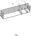
Figure 8 , it is convenient for the components of the automobile transportation rack for the container to be transported and stored as the components are detachably connected, and the storage lengths of the components after being disassembled are less than 2300 mm, thus it is possible to take full advantage of the internal width of thecontainer 100 and increase the loading capacity when the automobile transportation racks for the container are shipped. Even an automobile transportation rack for the container comprising fourupright posts 10, one frontwheel fixing frame 30, one rearwheel fixing frame 20, two top transversal support bars 40 and a bottom tire retainer bracket is concerned, the total weight of a single set will not exceed 400 KG - Now, reference will be made to
Figures 9 to 11 to describe the process of assembling the automobile transportation rack for the container according to the present invention and using the same to ship vehicles. The firstupright post 11 is firstly nested into the secondupright post 12, and the relative position between the channel steel of the secondupright post 12 at the lower end and the profile plate is adjusted in accordance with a preset position, and then the two are connected using a fastening bolt. When each of theupright posts 10 is assembled as stated above, the two pairs ofupright posts 10 in a bilateral symmetry are placed into thecontainer 100 in accordance with preset positions, so that the profile plate of each of theupright posts 10 abuts against the side plate of thecontainer 100. Then, the frontwheel fixing frame 30 and the rearwheel fixing frame 20 are respectively connected with theshaft sleeve 13 of theupright post 10. Finally, the tapered connector (i.e., the first andsecond bar connectors 411, 421) of thetransversal support bar 40 is inserted into the top of the firstupright posts 11 of the left and right upright posts 10 arranged opposite to each other and then the firstupright post 11 is lifted up to a preset position, then the firstupright post 11 and the secondupright post 12 are locked using a retainer pin, and a right-left-handed screw 43 is adjusted so as to cause thetransversal support bar 40 to abut closely against the upright posts 10. In this manner, the assemble of the automobile transportation rack for the container according to the present invention has been completed. - As shown in
Fig.9 , thefirst automobile 201 is driven into the forewheel transportation frame 1 and the rearwheel transportation frame 2 and parked there, reverses from theend door 101 of thecontainer 100 into thecontainer 100, and the front wheels and rear wheels of thefirst automobile 201 are respectively carried on the frontwheel fixing frame 30 and the rearwheel fixing frame 40. - As shown in
Figures 3 ,4 and10 , the frontwheel fixing frame 30 and the rearwheel fixing frame 40, which carry thefirst automobile 201, are lifted to a preset height with the manual chain, and the front wheels and the frontwheel fixing frame 30 as well as the rear wheels and the rearwheel fixing frame 40 could be secured with fasteners, such as a binding tape. - It should be noted that, in the illustrated embodiments, it is desirable that the height of the front
wheel fixing frame 30 is raised higher than the height at which the rearwheel fixing frame 40 is lifted, this is because the heavier components, such as the engine and the transmission, of a conventional vehicle are located at the front of the vehicle, so that the center of gravity of the vehicle is at the front, if the front wheel is lower than the rear wheel, then the acceleration or deceleration in the driving could cause the vehicle, as the inertia effect, to incline and dash downward out of the automobile transportation rack for the container in forward direction, that is, toward the direction of the front wheel,. - Therefore, to match the inclination occurred in the above process of lifting the vehicles, the rear
wheel fixing frame 40 rotates around the shaft sleeve connected thereto with respect to theupright post 10 in the lifting process, and the frontwheel fixing frame 30 also rotates around the shaft sleeve connected thereto with respect to theupright post 10. Further, due to the fact that the wheel base of the first automobile 201 (or, the distance between the front wheel and the rear wheel) is constant, when the front wheel and the rear wheel are not in the same horizontal plane, the frontwheel fixing frame 30 moves close to the rearwheel fixing frame 40, that is, in the illustrated embodiments, theslider hole 331 of the frontwheel fixing frame 30 is connected to the protrusion of the shaft sleeve and is fixed with respect to theupright post 10, and the frontwheel fixing frame 30 moves close to the rearwheel fixing frame 40 with respect to theslider 33. When the frontwheel fixing frame 30 and the rearwheel fixing frame 40 are raised to a preset height, the retainer pin can be attached so as to prevent theslider 33 from continuing sliding. - As shown in
Figures 6 and11 , the bottom tire fixing frame is connected to theupright post 10, and thesecond automobile 202 is driven into a preset position, then thesecond automobile 202 is fastened using a fastener, such as a conventional retaining band, thus completing the loading of the two automobiles. - As shown in
Figure 12 , the foregoing operations may be repeated for the following two vehicles, then loading of the40HC container 100 could be completed with a total of four automobiles including the third andfourth automobiles - According to another aspect of the present invention, there is further provided a
container 100 comprising the above mentioned automobile transportation rack for the container. As shown inFigure 13 , for example, one40HC container 100 may comprise two sets of automobile transportation rack for the container for loading four automobiles, or comprise one set of automobile transportation rack for the container for loading three large-sized automobiles. As described above, the respective locations of the profile plate, theupright post 10, the forewheel transportation frame 1 and the rearwheel transportation frame 2 may be calculated in advance according to the type of the vehicles before loading the same. - Unless defined otherwise, the technical and scientific terms used herein have the same meaning as commonly understood by one of ordinary skilled person in the art to which this invention pertains. The terminology used herein is for the purpose of describing particular implementations only and is not intended to be limiting of the present invention. As used herein, terms such as "parts" are used to denote a single part or a combination of several parts. The terms such as "assemble", "provide" and the like appeared herein may mean that one component is directly attached to another component, or that one component is attached to another component through a middleware.
Claims (14)
- An automobile transportation rack for a container (100), the container (100) comprising side walls, a bottom plate and a top plate, comprising:two pairs of upright posts (10) for arrangement in the container (100) to abut against the side walls and the bottom plate, the upright posts (10) having connecting portions;a transversal support bar (40);a front wheel fixing frame (30) connected between one of the two pairs of the upright posts (10) and movable vertically with respect to the upright posts (10) through the connecting portion; anda rear wheel fixing frame (20) connected between the other pair of the upright posts (10) and movable vertically with respect to the upright posts (10) through the connecting portion;wherein each of the two pairs of the upright posts (10), the transversal support bar (40), the front wheel fixing frame (30) and the rear wheel fixing frame (20) are detachably assembled to each other,characterized in that each upright post (10) comprises a top coupling portion (14) at the top thereof and a bottom coupling portion (15) at the bottom thereof, the bottom coupling portion (15) is configured to be used for connecting with the bottom plate, the top coupling portion (14) and the bottom coupling portion (15) each has a profile plate of a shape identical to that of the corrugation of the side walls of the container (100) and the transversal support bar (40) is adjustably connectable between the tops of each pair of the upright posts (10) so that the upright posts (10) are configured to abut against the side walls, the transversal support bar (40) connects the top coupling portions (14) of a pair of the upright posts (10), the transversal support bar (40) comprises a length adjustment mechanism for adjusting the length of the transversal support bar (40) and the length adjustment mechanism is used for lengthening the length of the transversal support bar (40) in a width direction of the container (100) so that the profile plates are configured to abut against the side walls of the container (100).
- The automobile transportation rack according to claim 1, characterized in that, the upright posts (10) comprise a first upright post (11) and a second upright post (12), the first upright post (11) is telescopically nested in the second upright post (12) for achieving a length of either one of the first and second upright posts (11, 12) to be less than an internal width of the container (100).
- The automobile transportation rack according to claim 2, characterized in that, the top coupling portion (14) is located at the top end of the first upright post (11), the bottom coupling portion (15) is located at the bottom end of the second upright post (12).
- The automobile transportation rack according to claim 1, characterized in that, the top coupling portion (14) is provided with a wire loop (143) for connecting with a vehicle moving apparatus.
- The automobile transportation rack according to claim 2, characterized in that, the connecting portion is a shaft sleeve (13) provided on the second upright post (12) and movable vertically with respect to the second upright post (12), the shaft sleeve (13) comprises a shaft sleeve body (131) nested on the second upright post (12) and a protrusion (132) protruding in the radial direction of the shaft sleeve body (131).
- The automobile transportation rack according to claim 5, characterized in that, location holes (121) are disposed on the second upright post (12), and the shaft sleeve (13) is secured to the second upright post (12) with pin shafts passing through the location holes (121).
- The automobile transportation rack according to claim 1, characterized in that, the front wheel fixing frame (30) and the rear wheel fixing frame (20) each comprises a first transversal beam (31a, 21a) and a second transversal beam (31b, 21b) which form a recess, and connecting beams (32, 22) connecting the first transversal beam (31a, 21a) and the second transversal beam (31b, 21b), the connecting beam (32, 22) is provided with a mating part for cooperating with the connecting portion thereon.
- The automobile transportation rack according to claim 7, characterized in that, the mating part is a slider (33) with a hole (331), and the slider (33) is provided on the connecting beam (32, 22) and movable with respect to the connecting beam (32, 22) in a direction perpendicular to the first transversal beam (31a, 21a) and the second transversal beam (31b, 21b) .
- The automobile transportation rack according to claim 8, characterized in that, a retainer for retaining the slider (33) is disposed on the connecting beam (32, 22).
- The automobile transportation rack according to claim 1, characterized in that, the top coupling portion (14) has an upward opening (142), the transversal support bar (40) has a connector (411, 421) for extending into the opening (142).
- The automobile transportation rack according to claim 1, characterized in that, the transversal support bar (40) comprises a first bar (41) and a second bar (42), the length adjustment mechanism is a right-left-handed screw (43) connected between the first bar (41) and the second bar (42).
- The automobile transportation rack according to claim 1, characterized in that, further comprising a bottom tire fixing frame (50) connected with the pair of upright posts (10) by stop pins for preventing movement of a lower vehicle, the bottom tire fixing frame (50) being configured as an integral fixing frame or a separable fixing frame.
- The automobile transportation rack according to claim 12, characterized in that, the integral fixing frame comprises a first bracket (51a) and a second bracket (51b) configured to be provided along the longitudinal direction of the vehicle, and a tire retainer bracket (52) located between the first bracket (51a) and the second bracket (51b).
- A container (100) comprising the automobile transportation rack according to any one of claims 1-13.
Applications Claiming Priority (2)
| Application Number | Priority Date | Filing Date | Title |
|---|---|---|---|
| CN201610656064.6A CN107720012B (en) | 2016-08-11 | 2016-08-11 | Vehicle transport rack for container and container having the same |
| PCT/CN2016/111476 WO2018028112A1 (en) | 2016-08-11 | 2016-12-22 | Automobile transport frame for use in container, and container having same |
Publications (3)
| Publication Number | Publication Date |
|---|---|
| EP3498632A1 EP3498632A1 (en) | 2019-06-19 |
| EP3498632A4 EP3498632A4 (en) | 2020-03-11 |
| EP3498632B1 true EP3498632B1 (en) | 2025-04-30 |
Family
ID=61161636
Family Applications (1)
| Application Number | Title | Priority Date | Filing Date |
|---|---|---|---|
| EP16912566.3A Active EP3498632B1 (en) | 2016-08-11 | 2016-12-22 | Automobile transport frame for use in container, and container having same |
Country Status (4)
| Country | Link |
|---|---|
| EP (1) | EP3498632B1 (en) |
| CN (1) | CN107720012B (en) |
| ES (1) | ES3033527T3 (en) |
| WO (1) | WO2018028112A1 (en) |
Families Citing this family (3)
| Publication number | Priority date | Publication date | Assignee | Title |
|---|---|---|---|---|
| CN108327609A (en) * | 2018-03-20 | 2018-07-27 | 广西海本科技有限公司 | A kind of automobile support, moving trolley and hoistable platform |
| CN110589269B (en) * | 2018-06-12 | 2025-06-06 | 大连中集特种物流装备有限公司 | Transport storage device |
| CN115178042B (en) * | 2022-07-11 | 2023-11-10 | 江西宝郡建筑工程有限公司 | Fixed climbing frame spray set for building construction |
Family Cites Families (11)
| Publication number | Priority date | Publication date | Assignee | Title |
|---|---|---|---|---|
| US4963067A (en) * | 1986-12-18 | 1990-10-16 | G & G Intellectual Properties, Inc. | System for loading and transporting wheeled vehicles |
| GB2298842A (en) * | 1995-02-28 | 1996-09-18 | Treton Developments Inc | Motor vehicle transportation |
| EP1326791B1 (en) * | 2000-10-03 | 2006-06-07 | Martin Clive-Smith | Vehicle support frame |
| CN101314427B (en) * | 2007-06-01 | 2011-12-21 | 南通中集特种运输设备制造有限公司 | Carrier frame capable of being arranged in container and container including the carrier frame |
| CN201068303Y (en) * | 2007-06-01 | 2008-06-04 | 南通中集特种运输设备制造有限公司 | Vehicle transporting frame capable of being placed in container and container comprising the same |
| CN101332930B (en) * | 2007-06-26 | 2011-09-07 | 南通中集特种运输设备制造有限公司 | Container with transport structure and transport structure thereof |
| JP5390966B2 (en) * | 2009-07-07 | 2014-01-15 | 株式会社ロッコーエンジニアリング | Cargo rack |
| CN202464495U (en) * | 2012-03-01 | 2012-10-03 | 江西远成汽车技术股份有限公司 | Combined automobile transportation bracket for container |
| JP2013256326A (en) * | 2012-06-13 | 2013-12-26 | Rokko Engineering Co Ltd | Cargo rack |
| DE202015106050U1 (en) * | 2015-11-10 | 2016-02-11 | Martin Clive-Smith | Removable frame systems for vehicle transport |
| CN205931947U (en) * | 2016-08-11 | 2017-02-08 | 大连中集物流装备有限公司 | Automobile transportation puts up and has its container for container |
-
2016
- 2016-08-11 CN CN201610656064.6A patent/CN107720012B/en active Active
- 2016-12-22 EP EP16912566.3A patent/EP3498632B1/en active Active
- 2016-12-22 ES ES16912566T patent/ES3033527T3/en active Active
- 2016-12-22 WO PCT/CN2016/111476 patent/WO2018028112A1/en not_active Ceased
Also Published As
| Publication number | Publication date |
|---|---|
| EP3498632A1 (en) | 2019-06-19 |
| ES3033527T3 (en) | 2025-08-05 |
| EP3498632A4 (en) | 2020-03-11 |
| CN107720012B (en) | 2020-09-04 |
| WO2018028112A1 (en) | 2018-02-15 |
| CN107720012A (en) | 2018-02-23 |
Similar Documents
| Publication | Publication Date | Title |
|---|---|---|
| CN103201195B (en) | Removable frame system for vehicle transport | |
| US4124119A (en) | Automobile carrier for use on air cargo pallets | |
| EP3601101B1 (en) | Vehicle transport structures | |
| US3794375A (en) | Detachable vehicle enclosure | |
| US20120163940A1 (en) | Transport system | |
| US8567848B2 (en) | Modular headboard and application in tarpaulin industry | |
| US9981590B2 (en) | Individual, universal, removable, load-bearing pallet for car-carrying vehicle | |
| KR101984124B1 (en) | Transport device and transport means therewith | |
| EP3498632B1 (en) | Automobile transport frame for use in container, and container having same | |
| WO2019056824A1 (en) | Vehicle transporting frame | |
| CN205931947U (en) | Automobile transportation puts up and has its container for container | |
| CN107840016B (en) | Corner post and foldable container | |
| US5924248A (en) | Collapsible frame device | |
| KR20040103337A (en) | Transport apparatus | |
| CN221317710U (en) | Carrying device | |
| US20250346424A1 (en) | A racking system for cars in a container | |
| CN117734556A (en) | Carrier assembly and carrier apparatus | |
| JP4310630B2 (en) | Stackable carts | |
| CN221213673U (en) | Carrier assembly and carrier apparatus | |
| EP1481843B1 (en) | Transport apparatus for cars | |
| CN118083386A (en) | Transport equipment | |
| JPH05294381A (en) | Loading device of car for container | |
| KR950014413B1 (en) | Car loading apparatus | |
| GB2108934A (en) | Knock-down transport containers | |
| GB2594645A (en) | Vehicle transportation systems |
Legal Events
| Date | Code | Title | Description |
|---|---|---|---|
| STAA | Information on the status of an ep patent application or granted ep patent |
Free format text: STATUS: THE INTERNATIONAL PUBLICATION HAS BEEN MADE |
|
| PUAI | Public reference made under article 153(3) epc to a published international application that has entered the european phase |
Free format text: ORIGINAL CODE: 0009012 |
|
| STAA | Information on the status of an ep patent application or granted ep patent |
Free format text: STATUS: REQUEST FOR EXAMINATION WAS MADE |
|
| 17P | Request for examination filed |
Effective date: 20181012 |
|
| AK | Designated contracting states |
Kind code of ref document: A1 Designated state(s): AL AT BE BG CH CY CZ DE DK EE ES FI FR GB GR HR HU IE IS IT LI LT LU LV MC MK MT NL NO PL PT RO RS SE SI SK SM TR |
|
| AX | Request for extension of the european patent |
Extension state: BA ME |
|
| DAV | Request for validation of the european patent (deleted) | ||
| DAX | Request for extension of the european patent (deleted) | ||
| A4 | Supplementary search report drawn up and despatched |
Effective date: 20200207 |
|
| RIC1 | Information provided on ipc code assigned before grant |
Ipc: B65D 90/00 20060101ALI20200203BHEP Ipc: B65D 85/68 20060101AFI20200203BHEP |
|
| STAA | Information on the status of an ep patent application or granted ep patent |
Free format text: STATUS: EXAMINATION IS IN PROGRESS |
|
| 17Q | First examination report despatched |
Effective date: 20210330 |
|
| GRAP | Despatch of communication of intention to grant a patent |
Free format text: ORIGINAL CODE: EPIDOSNIGR1 |
|
| STAA | Information on the status of an ep patent application or granted ep patent |
Free format text: STATUS: GRANT OF PATENT IS INTENDED |
|
| INTG | Intention to grant announced |
Effective date: 20241210 |
|
| GRAS | Grant fee paid |
Free format text: ORIGINAL CODE: EPIDOSNIGR3 |
|
| GRAA | (expected) grant |
Free format text: ORIGINAL CODE: 0009210 |
|
| STAA | Information on the status of an ep patent application or granted ep patent |
Free format text: STATUS: THE PATENT HAS BEEN GRANTED |
|
| AK | Designated contracting states |
Kind code of ref document: B1 Designated state(s): AL AT BE BG CH CY CZ DE DK EE ES FI FR GB GR HR HU IE IS IT LI LT LU LV MC MK MT NL NO PL PT RO RS SE SI SK SM TR |
|
| REG | Reference to a national code |
Ref country code: CH Ref legal event code: EP Ref country code: GB Ref legal event code: FG4D |
|
| REG | Reference to a national code |
Ref country code: IE Ref legal event code: FG4D |
|
| REG | Reference to a national code |
Ref country code: DE Ref legal event code: R096 Ref document number: 602016092107 Country of ref document: DE |
|
| REG | Reference to a national code |
Ref country code: ES Ref legal event code: FG2A Ref document number: 3033527 Country of ref document: ES Kind code of ref document: T3 Effective date: 20250805 |
|
| REG | Reference to a national code |
Ref country code: NL Ref legal event code: MP Effective date: 20250430 |
|
| REG | Reference to a national code |
Ref country code: AT Ref legal event code: MK05 Ref document number: 1789878 Country of ref document: AT Kind code of ref document: T Effective date: 20250430 |
|
| PG25 | Lapsed in a contracting state [announced via postgrant information from national office to epo] |
Ref country code: PT Free format text: LAPSE BECAUSE OF FAILURE TO SUBMIT A TRANSLATION OF THE DESCRIPTION OR TO PAY THE FEE WITHIN THE PRESCRIBED TIME-LIMIT Effective date: 20250901 Ref country code: FI Free format text: LAPSE BECAUSE OF FAILURE TO SUBMIT A TRANSLATION OF THE DESCRIPTION OR TO PAY THE FEE WITHIN THE PRESCRIBED TIME-LIMIT Effective date: 20250430 |
|
| REG | Reference to a national code |
Ref country code: LT Ref legal event code: MG9D |
|
| PG25 | Lapsed in a contracting state [announced via postgrant information from national office to epo] |
Ref country code: GR Free format text: LAPSE BECAUSE OF FAILURE TO SUBMIT A TRANSLATION OF THE DESCRIPTION OR TO PAY THE FEE WITHIN THE PRESCRIBED TIME-LIMIT Effective date: 20250731 Ref country code: NO Free format text: LAPSE BECAUSE OF FAILURE TO SUBMIT A TRANSLATION OF THE DESCRIPTION OR TO PAY THE FEE WITHIN THE PRESCRIBED TIME-LIMIT Effective date: 20250730 |
|
| PG25 | Lapsed in a contracting state [announced via postgrant information from national office to epo] |
Ref country code: PL Free format text: LAPSE BECAUSE OF FAILURE TO SUBMIT A TRANSLATION OF THE DESCRIPTION OR TO PAY THE FEE WITHIN THE PRESCRIBED TIME-LIMIT Effective date: 20250430 Ref country code: NL Free format text: LAPSE BECAUSE OF FAILURE TO SUBMIT A TRANSLATION OF THE DESCRIPTION OR TO PAY THE FEE WITHIN THE PRESCRIBED TIME-LIMIT Effective date: 20250430 |
|
| PG25 | Lapsed in a contracting state [announced via postgrant information from national office to epo] |
Ref country code: BG Free format text: LAPSE BECAUSE OF FAILURE TO SUBMIT A TRANSLATION OF THE DESCRIPTION OR TO PAY THE FEE WITHIN THE PRESCRIBED TIME-LIMIT Effective date: 20250430 |
|
| PG25 | Lapsed in a contracting state [announced via postgrant information from national office to epo] |
Ref country code: HR Free format text: LAPSE BECAUSE OF FAILURE TO SUBMIT A TRANSLATION OF THE DESCRIPTION OR TO PAY THE FEE WITHIN THE PRESCRIBED TIME-LIMIT Effective date: 20250430 |
|
| PG25 | Lapsed in a contracting state [announced via postgrant information from national office to epo] |
Ref country code: AT Free format text: LAPSE BECAUSE OF FAILURE TO SUBMIT A TRANSLATION OF THE DESCRIPTION OR TO PAY THE FEE WITHIN THE PRESCRIBED TIME-LIMIT Effective date: 20250430 |
|
| PG25 | Lapsed in a contracting state [announced via postgrant information from national office to epo] |
Ref country code: RS Free format text: LAPSE BECAUSE OF FAILURE TO SUBMIT A TRANSLATION OF THE DESCRIPTION OR TO PAY THE FEE WITHIN THE PRESCRIBED TIME-LIMIT Effective date: 20250731 |
|
| PG25 | Lapsed in a contracting state [announced via postgrant information from national office to epo] |
Ref country code: IS Free format text: LAPSE BECAUSE OF FAILURE TO SUBMIT A TRANSLATION OF THE DESCRIPTION OR TO PAY THE FEE WITHIN THE PRESCRIBED TIME-LIMIT Effective date: 20250830 |
|
| PG25 | Lapsed in a contracting state [announced via postgrant information from national office to epo] |
Ref country code: LV Free format text: LAPSE BECAUSE OF FAILURE TO SUBMIT A TRANSLATION OF THE DESCRIPTION OR TO PAY THE FEE WITHIN THE PRESCRIBED TIME-LIMIT Effective date: 20250430 |
|
| PG25 | Lapsed in a contracting state [announced via postgrant information from national office to epo] |
Ref country code: SM Free format text: LAPSE BECAUSE OF FAILURE TO SUBMIT A TRANSLATION OF THE DESCRIPTION OR TO PAY THE FEE WITHIN THE PRESCRIBED TIME-LIMIT Effective date: 20250430 Ref country code: DK Free format text: LAPSE BECAUSE OF FAILURE TO SUBMIT A TRANSLATION OF THE DESCRIPTION OR TO PAY THE FEE WITHIN THE PRESCRIBED TIME-LIMIT Effective date: 20250430 |
|
| PGFP | Annual fee paid to national office [announced via postgrant information from national office to epo] |
Ref country code: BE Payment date: 20251223 Year of fee payment: 10 |
|
| PG25 | Lapsed in a contracting state [announced via postgrant information from national office to epo] |
Ref country code: CZ Free format text: LAPSE BECAUSE OF FAILURE TO SUBMIT A TRANSLATION OF THE DESCRIPTION OR TO PAY THE FEE WITHIN THE PRESCRIBED TIME-LIMIT Effective date: 20250430 |
|
| PG25 | Lapsed in a contracting state [announced via postgrant information from national office to epo] |
Ref country code: EE Free format text: LAPSE BECAUSE OF FAILURE TO SUBMIT A TRANSLATION OF THE DESCRIPTION OR TO PAY THE FEE WITHIN THE PRESCRIBED TIME-LIMIT Effective date: 20250430 |
|
| PG25 | Lapsed in a contracting state [announced via postgrant information from national office to epo] |
Ref country code: SK Free format text: LAPSE BECAUSE OF FAILURE TO SUBMIT A TRANSLATION OF THE DESCRIPTION OR TO PAY THE FEE WITHIN THE PRESCRIBED TIME-LIMIT Effective date: 20250430 Ref country code: RO Free format text: LAPSE BECAUSE OF FAILURE TO SUBMIT A TRANSLATION OF THE DESCRIPTION OR TO PAY THE FEE WITHIN THE PRESCRIBED TIME-LIMIT Effective date: 20250430 |
|
| PG25 | Lapsed in a contracting state [announced via postgrant information from national office to epo] |
Ref country code: IT Free format text: LAPSE BECAUSE OF FAILURE TO SUBMIT A TRANSLATION OF THE DESCRIPTION OR TO PAY THE FEE WITHIN THE PRESCRIBED TIME-LIMIT Effective date: 20250430 |