EP3498201B1 - Chirurgische ultraschallinstrumente zum versiegeln und/oder schneiden von gewebe - Google Patents
Chirurgische ultraschallinstrumente zum versiegeln und/oder schneiden von gewebe Download PDFInfo
- Publication number
- EP3498201B1 EP3498201B1 EP18211840.6A EP18211840A EP3498201B1 EP 3498201 B1 EP3498201 B1 EP 3498201B1 EP 18211840 A EP18211840 A EP 18211840A EP 3498201 B1 EP3498201 B1 EP 3498201B1
- Authority
- EP
- European Patent Office
- Prior art keywords
- tissue
- blade
- ultrasonic
- displacement
- drive signal
- Prior art date
- Legal status (The legal status is an assumption and is not a legal conclusion. Google has not performed a legal analysis and makes no representation as to the accuracy of the status listed.)
- Active
Links
Images



Classifications
-
- A—HUMAN NECESSITIES
- A61—MEDICAL OR VETERINARY SCIENCE; HYGIENE
- A61B—DIAGNOSIS; SURGERY; IDENTIFICATION
- A61B17/00—Surgical instruments, devices or methods
- A61B17/32—Surgical cutting instruments
- A61B17/320068—Surgical cutting instruments using mechanical vibrations, e.g. ultrasonic
- A61B17/320092—Surgical cutting instruments using mechanical vibrations, e.g. ultrasonic with additional movable means for clamping or cutting tissue, e.g. with a pivoting jaw
-
- A—HUMAN NECESSITIES
- A61—MEDICAL OR VETERINARY SCIENCE; HYGIENE
- A61B—DIAGNOSIS; SURGERY; IDENTIFICATION
- A61B17/00—Surgical instruments, devices or methods
- A61B17/28—Surgical forceps
- A61B17/29—Forceps for use in minimally invasive surgery
- A61B17/295—Forceps for use in minimally invasive surgery combined with cutting implements
-
- A—HUMAN NECESSITIES
- A61—MEDICAL OR VETERINARY SCIENCE; HYGIENE
- A61B—DIAGNOSIS; SURGERY; IDENTIFICATION
- A61B17/00—Surgical instruments, devices or methods
- A61B2017/00017—Electrical control of surgical instruments
- A61B2017/00022—Sensing or detecting at the treatment site
- A61B2017/00026—Conductivity or impedance, e.g. of tissue
-
- A—HUMAN NECESSITIES
- A61—MEDICAL OR VETERINARY SCIENCE; HYGIENE
- A61B—DIAGNOSIS; SURGERY; IDENTIFICATION
- A61B17/00—Surgical instruments, devices or methods
- A61B2017/00017—Electrical control of surgical instruments
- A61B2017/00022—Sensing or detecting at the treatment site
- A61B2017/00026—Conductivity or impedance, e.g. of tissue
- A61B2017/0003—Conductivity or impedance, e.g. of tissue of parts of the instruments
-
- A—HUMAN NECESSITIES
- A61—MEDICAL OR VETERINARY SCIENCE; HYGIENE
- A61B—DIAGNOSIS; SURGERY; IDENTIFICATION
- A61B17/00—Surgical instruments, devices or methods
- A61B17/32—Surgical cutting instruments
- A61B17/320068—Surgical cutting instruments using mechanical vibrations, e.g. ultrasonic
- A61B2017/320072—Working tips with special features, e.g. extending parts
- A61B2017/320074—Working tips with special features, e.g. extending parts blade
- A61B2017/320075—Working tips with special features, e.g. extending parts blade single edge blade, e.g. for cutting
-
- A—HUMAN NECESSITIES
- A61—MEDICAL OR VETERINARY SCIENCE; HYGIENE
- A61B—DIAGNOSIS; SURGERY; IDENTIFICATION
- A61B17/00—Surgical instruments, devices or methods
- A61B17/32—Surgical cutting instruments
- A61B17/320068—Surgical cutting instruments using mechanical vibrations, e.g. ultrasonic
- A61B17/320092—Surgical cutting instruments using mechanical vibrations, e.g. ultrasonic with additional movable means for clamping or cutting tissue, e.g. with a pivoting jaw
- A61B2017/320094—Surgical cutting instruments using mechanical vibrations, e.g. ultrasonic with additional movable means for clamping or cutting tissue, e.g. with a pivoting jaw additional movable means performing clamping operation
-
- A—HUMAN NECESSITIES
- A61—MEDICAL OR VETERINARY SCIENCE; HYGIENE
- A61B—DIAGNOSIS; SURGERY; IDENTIFICATION
- A61B17/00—Surgical instruments, devices or methods
- A61B17/32—Surgical cutting instruments
- A61B17/320068—Surgical cutting instruments using mechanical vibrations, e.g. ultrasonic
- A61B17/320092—Surgical cutting instruments using mechanical vibrations, e.g. ultrasonic with additional movable means for clamping or cutting tissue, e.g. with a pivoting jaw
- A61B2017/320095—Surgical cutting instruments using mechanical vibrations, e.g. ultrasonic with additional movable means for clamping or cutting tissue, e.g. with a pivoting jaw with sealing or cauterizing means
-
- A—HUMAN NECESSITIES
- A61—MEDICAL OR VETERINARY SCIENCE; HYGIENE
- A61B—DIAGNOSIS; SURGERY; IDENTIFICATION
- A61B90/00—Instruments, implements or accessories specially adapted for surgery or diagnosis and not covered by any of the groups A61B1/00 - A61B50/00, e.g. for luxation treatment or for protecting wound edges
- A61B90/06—Measuring instruments not otherwise provided for
- A61B2090/064—Measuring instruments not otherwise provided for for measuring force, pressure or mechanical tension
Definitions
- the present disclosure relates to ultrasonic surgical instruments and, more particularly, to ultrasonic surgical instruments and methods for sealing and/or cutting tissue.
- Ultrasonic surgical instruments utilize ultrasonic energy, i.e., ultrasonic vibrations, to treat tissue. More specifically, ultrasonic surgical instruments utilize mechanical vibration energy transmitted at ultrasonic frequencies to seal and/or cut tissue.
- an ultrasonic surgical instrument is configured to transmit ultrasonic energy produced by a generator and transducer assembly along a waveguide to an end effector that is spaced-apart from the generator and transducer assembly.
- the end effector is configured to transmit the ultrasonic energy to tissue to treat the tissue, e.g., to seal and/or cut tissue.
- a portable power source e.g., a battery
- the generator and transducer assembly are mounted on the handheld instrument itself, while the waveguide interconnects the generator and transducer assembly and the end effector.
- Corded ultrasonic instruments operate in similar fashion except that, rather than having the generator and power source mounted on the handheld instrument itself, the handheld instrument is configured to connect to a standalone power supply and/or generator via a corded connection.
- WO 2017/123844 A1 discloses an ultrasonic surgical instrument.
- distal refers to the portion that is being described which is further from a user
- proximal refers to the portion that is being described which is closer to a user
- an ultrasonic surgical system including an ultrasonic generator configured to output a drive signal, an ultrasonic transducer coupled to the ultrasonic generator and configured to receive the drive signal and output mechanical motion in response thereto, a waveguide coupled to the ultrasonic transducer and configured to transmit the mechanical motion therealong, a blade disposed at a distal end portion of the waveguide, a sensor, and a controller.
- the blade is configured to oscillate in response to receipt of the mechanical motion from the waveguide.
- the blade defines a displacement when oscillating.
- the sensor is configured to sense a property indicative of tension on tissue.
- the controller is configured to adjust the drive signal to thereby adjust the displacement based upon the sensed property.
- the senor is configured to sense a force on the waveguide.
- the sensor is configured to sense an impedance of the ultrasonic transducer.
- the controller is configured to adjust the drive signal to increase the displacement of the blade.
- the controller is configured to adjust the drive signal to decrease the displacement of the blade.
- an activation switch is operably coupled to the ultrasonic generator and selectively activatable in a "CUT” mode and a "SEAL" mode.
- the controller when the activation switch is activated in the "SEAL" mode, if the sensed property indicates tension on tissue is increased, the controller is configured to adjust the drive signal to decrease the displacement of the blade.
- the controller when the activation switch is activated in the "CUT" mode, if the sensed property indicates tension on tissue is increased, the controller is configured to adjust the drive signal to increase the displacement of the blade.
- a handle assembly supports the ultrasonic transducer thereon and the waveguide extends distally from the handle assembly.
- the handle assembly may further support the ultrasonic generator and a battery assembly, configured to power the ultrasonic generator to produce the drive signal, thereon.
- the controller is configured to control an amount of power delivered from the battery assembly to the ultrasonic generator to thereby adjust the drive signal.
- a method of treating tissue includes applying a drive signal to an ultrasonic transducer to oscillate an ultrasonic blade adjacent tissue, sensing a property indicative of a tension on the tissue, and adjusting the drive signal applied to the ultrasonic transducer based upon the sensed property to thereby adjust a displacement of the blade.
- sensing the property includes sensing a force on a waveguide coupled to the ultrasonic blade.
- sensing the property includes sensing an impedance of the ultrasonic transducer.
- the drive signal is adjusted to increase the displacement of the blade.
- the drive signal is adjusted to decrease the displacement of the blade.
- the method further includes determining whether a "CUT" mode of operation or a "SEAL" mode of operation is selected and adjusting the drive signal applied to the ultrasonic transducer based upon the sensed property and the selected mode of operation to thereby adjust the displacement.
- the drive signal in the "SEAL" mode of operation, if the sensed property indicates tension on tissue is increased, the drive signal is adjusted to decrease the displacement of the blade. Additionally or alternatively, in the "CUT" mode, if the sensed property indicates tension on tissue is increased, the drive signal is adjusted to increase the displacement of the blade.
- adjusting the drive signal includes adjusting an amount of power delivered from a power source to an ultrasonic generator configured to output the drive signal.
- the present disclosure provides ultrasonic surgical instruments and methods for sealing and/or cutting tissue. More specifically, the ultrasonic surgical instruments and methods of the present disclosure are configured to adjust the ultrasonic energy output, e.g., the displacement of the ultrasonic blade, based upon the tension on tissue, to facilitate sealing of tissue or cutting of tissue.
- An ultrasonic surgical instrument exemplifying the aspects and features of the present disclosure is shown generally identified by reference numeral 10. For the purposes herein, ultrasonic surgical instrument 10 is generally described. Aspects and features of ultrasonic surgical instrument 10 not germane to the understanding of the present disclosure are omitted to avoid obscuring such aspects and features of the present disclosure in unnecessary detail. Further, the aspects and features of the present disclosure are equally applicable for use with any other suitable ultrasonic surgical instrument.
- Ultrasonic surgical instrument 10 generally includes a handle assembly 12, an elongated body 14 extending distally from handle assembly 12, and a tool assembly 16 disposed at a distal end portion of elongated body 14 and including a blade 32 and a clamp member 58.
- Handle assembly 12 supports a battery assembly 18 and an ultrasonic transducer and generator assembly ("TAG") 20, and includes a rotatable nozzle 22, an activation button 24, and a clamp trigger 26.
- Battery assembly 18 and TAG 20 are each releasably secured to handle assembly 12, and are removable therefrom to facilitate disposal of the entire device, with the exception of battery assembly 18 and TAG 20.
- any or all of the components of ultrasonic surgical instrument 10 be configured as disposable single-use components or sterilizable multi-use components.
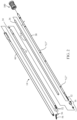
- elongated body 14 of ultrasonic surgical instrument 10 includes a waveguide 30 which extends distally from handle assembly 12 to tool assembly 16.
- a distal end portion of waveguide 30 defines blade 32 of tool assembly 16.
- a proximal end portion of waveguide 30 is configured to engage TAG 20 ( FIGS. 1 and 3 ), as detailed below.
- An isolation tube 36 is positioned about waveguide 30 to prevent the transfer of ultrasonic energy from waveguide 30 to an inner support tube 42.
- One or more seal rings 34 is disposed about waveguide 30 to maintain spacing between waveguide 30 and isolation tube 36 while inhibiting fluid passage therebetween. Seal ring(s) 34 may be disposed at a node point(s) along waveguide 30 or in another suitable position(s).
- Waveguide 30 and inner support tube 42 are rotatably coupled to rotatable nozzle 22 ( FIG. 1 ) such that rotation of nozzle 22 ( FIG. 1 ) effects corresponding rotation of inner support tube 42 and waveguide 30.
- An actuator tube 66 which, as detailed below, is coupled to inner support tube 42, is similarly rotated upon rotation of nozzle 22 ( FIG. 1 ).
- Inner support tube 42 is positioned about isolation tube 36 and includes a distal end portion having a pair of spaced clamp support arms 52.
- Spaced clamp support arms 52 are configured to pivotally engage pivot members 56 (only one of which is visible in FIG. 2 ) formed on clamp jaw 58 of tool assembly 16 to enable pivoting of clamp jaw 58 between an open position, wherein clamp jaw 58 is spaced from blade 32, and a closed position, wherein clamp jaw 58 is approximated relative to blade 32.
- Clamp jaw 58 is moved between the open and closed positions in response to actuation of clamp trigger 26 ( FIG. 1 ).
- Outer actuator tube 66 is slidably supported about inner support tube 42 and is operably coupled to clamp jaw 58 such that, as actuator tube 66 is slid about inner support tube 42 between an advanced position and a retracted position, clamp jaw 58 is pivoted from the open position to the closed position.
- a proximal end of outer actuator tube 66 is operably coupled with rotatable nozzle 22 ( FIG. 1 ) such that outer actuator tube 66 is rotatably secured to but slidable relative to rotatable nozzle 22 ( FIG. 1 ).
- the proximal end of outer actuator tube 66 is also operably coupled with a drive mechanism 100.
- drive mechanism 100 is supported within and configured for linear movement relative to handle assembly 12.
- Handle assembly 12 also includes the aforementioned clamp trigger 26, which is operably coupled with drive mechanism 100 such that, in use, when clamping trigger 26 is compressed towards battery assembly 18, drive mechanism 100 is moved to thereby move outer actuator tube 66 from the advanced position to the retracted position to pivot clamp jaw 58 from the open position to the closed position in relation to blade 32.
- Drive mechanism 100 is further configured to limit the application of clamping force to tissue grasped between clamp jaw 58 and blade 32.
- a spring (not explicitly shown) may be provided to bias clamping trigger 26 towards the initial position and, thus, clamp jaw 58 towards the open position.
- Activation button 24 is supported on handle assembly 12. When activation button 24 is activated in an appropriate manner, an underlying switch assembly 170 is activated to effect communication between battery assembly 18 and TAG 20.
- switch assembly 170 may be configured as a two operational mode switch assembly 170 enabling activation from an "OFF" condition to either a "CUT” mode of operation or a “SEAL” mode of operation, depending upon the manner in which activation button 24 is activated (see FIGS. 4A-4B ).
- a switch assembly 1070 may be provided that enables activation from an "OFF” condition to an "ON” condition in response to appropriate activation of activation button 24 (see FIGS. 5A-5B ) or from an “OFF” condition to either a "LOW” power mode of operation or a "HIGH” power mode of operation.
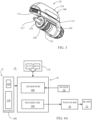
- battery assembly 18 is connected to a lower end of handle assembly 12 to define a fixed handgrip portion of handle assembly 12 and includes an outer housing 200 that houses one or more battery cells 210 and a microcontroller 220 including a processor and a memory (see FIG 4A ).
- a series of contacts (not explicitly shown) disposed on outer housing 200 enable communication of power and/or control signals between the internal components of battery assembly 18, switch assembly 170 ( FIG. 4A ), and TAG 20, although contactless communication therebetween is also contemplated.
- TAG 20 includes a generator 300 and an ultrasonic transducer 350.
- Generator 300 includes an outer housing 310 that houses the internal operating components thereof, e.g., drive signal generating circuitry, a microcontroller, and a memory (not explicitly shown).
- TAG 20 further includes one or more support members 340 extending from outer housing 310 of generator 300 that define one or more cradles for rotatably supporting ultrasonic transducer 350.
- Ultrasonic transducer 350 includes a piezoelectric stack 352 and a forwardly extending horn 354.
- Horn 354 is configured to threadably engage the proximal end of waveguide 30 ( FIG. 2 ), although other suitable engagement mechanisms are also contemplated.
- a series of contacts 312 associated with TAG 20 enable communication of power and/or control signals between TAG 20, battery assembly 18, and switch assembly 170 ( FIG. 4A ), although contactless communication therebetween is also contemplated.
- switch assembly 170 signals battery cells 210 ( FIG. 4A ) to provide power to generator 300 of TAG 20 which, in turn, uses this power to provide a drive signal to ultrasonic transducer 350 of TAG 20.
- Ultrasonic transducer 350 converts the drive signal into high frequency mechanical motion. This high frequency mechanical motion produced by ultrasonic transducer 350 is transmitted to blade 32 via waveguide 30 such that blade 32 oscillates within the ultrasonic frequency range. In this manner, blade 32 may be utilized to treat, e.g., seal and/or cut, tissue adjacent to blade 32 or clamped between blade 32 and clamp jaw 58.
- the power provided from battery cells 210 to generator 300 effects the drive signal provided from generator 300 to ultrasonic transducer 350 which, in turn, effects the mechanical motion produced by ultrasonic transducer 350 and, thus, the displacement of blade 32 as blade 32 oscillates within the ultrasonic frequency range.
- the power provided from battery cells 210 to generator 300 may be varied to vary the drive signal provided from generator 300 to ultrasonic transducer 350, thereby varying the displacement of blade 32, although other suitable controls for varying the drive signal and, thus, the displacement of blade 32 are also contemplated.
- Different displacements of blade 32 affect tissue in different manners. For example, a greater displacement of blade 32 results in relatively faster tissue cutting and relatively less tissue sealing, while a smaller displacement of blade 32 results in relatively less tissue cutting and relatively better tissue sealing. Accordingly, where tissue cutting is desired, a greater displacement of blade 32 is utilized. Where tissue sealing is desired, a lesser displacement of blade 32 is utilized.
- ultrasonic surgical instrument 10 is provided with one or more sensors 70 ( FIG. 4A ) configured to sense a force that correlates to a relative amount of tension on tissue.
- Sensor 70 is coupled to the microcontroller (not shown) of generator 300 and/or microcontroller 220 of battery assembly 18 to enable the drive signal provided from generator 300 to ultrasonic transducer 350 to be adjusted based upon whether or not, or the extent to which, there is tension on tissue, as detailed below.
- Sensor 70 more specifically, operates to sense, directly or indirectly, a relative amount of force acting on blade 32, which is indicative of the tension on tissue, e.g., whether blade 32 is applying greater force to tissue such that tissue is relatively more tensioned or whether blade 32 is applying less force to tissue such that tissue is relatively less tensioned.
- Sensor 70 may take various forms and/or may be disposed at various positions on ultrasonic surgical instrument 10 ( FIG. 1 ). Exemplary sensors 70 and positions of sensor 70 on ultrasonic surgical instrument 10 ( FIG. 1 ) are detailed below; however, any suitable sensor 70 in any suitable position may be utilized in accordance with the present disclosure.
- Sensor 70 may be configured as a strain gauge or other suitable progressive sensor configured to sense a relative degree of force across a range.
- sensor 70 may be configured as a contact (ON/OFF) sensor or other suitable sensor configured to sense whether a force exceeds a threshold force.
- sensor 70 is disposed at location "L1" at the junction between the fixed handle portion of handle assembly 12 and the body portion of handle assembly 12, since force applied by a user to handle assembly 12 at "L1" to urge blade 32 into tissue to tension tissue is indicative of the tension on tissue.
- sensor 70 in examples, may be disposed at location "L2" or “L3" on waveguide 30, since force applied by blade 32 to tissue will result in a torque applied to waveguide 30 that is indicative of the tension on tissue.
- Locations “L2” and “L3” may be at nodes of waveguide 30, e.g., adjacent to the one or more seal rings 34 disposed about waveguide 30, or at other suitable positions along waveguide 30.
- sensor 70 may be configured as a strain gauge printed directly onto waveguide 30 or may be any other suitable sensor coupled to waveguide 30 in any other suitable manner.
- sensor 70 may be disposed at location "L4" on the interior of isolation tube 36, since force applied by blade 32 to tissue will result in a torque applied to waveguide 30 which, in turn, will result in a force on isolation tube 36 (from direct contact with waveguide 30 or indirectly via contact of component(s) therebetween) that is indicative of the tension on tissue.
- waveguide 30 may include an outwardly-extending protrusion (not explicitly shown) and/or sensor 70 may protrude inwardly from isolation tube 36 to facilitate contact between waveguide 30 and sensor 70.
- sensor 70 may be positioned adjacent one or more of the seal rings 34 disposed about waveguide 30 between waveguide 30 and isolation tube 36. Instead of being disposed at location "L4,” sensor 70 may alternatively be disposed at any suitable position on isolation tube 36.
- sensor 70 may be disposed at location "L5,” on horn 354 of transducer 350 of TAG 20. Similarly as with waveguide 30 ( FIG. 2 ), the force applied by blade 32 to tissue will result in a torque applied to horn 354 that is indicative of the tension on tissue.
- sensor 70 is disposed at location "L6" and is configured as an impedance sensor configured to sense the impedance of transducer 350. With a plurality of readings of the impedance of transducer 350 from sensor 70 over time, the resultant impedance curve can be analyzed to determine whether blade 32 is putting tension (or relatively more tension) on tissue or if blade 32 is not putting tension (or relatively less tension) on tissue, thus indicating the tension on tissue. More specifically, if the change in impedance over time is above a threshold, sensor 70 may indicate that there is tension (or relatively more tension) on tissue. On the other hand, if the change in impedance is below the threshold, sensor 70 may indicate that there is no tension (or relatively less tension) on tissue. Other suitable impedance to tissue tension correlations are also contemplated. Other suitable sensors configured to determine tension on tissue based upon electrical characteristics of transducer 350, battery assembly 18, and/or generator 300 are also contemplated.
- sensor 70 is coupled to the microcontroller (not shown) of generator 300 and/or microcontroller 220 of battery assembly 18 to enable the drive signal provided from generator 300 to ultrasonic transducer 350 to be adjusted, to thereby adjust the displacement of blade 32. More specifically, displacement of blade 32 is adjusted, e.g., increased, decreased, or maintained, based upon whether tension on tissue (or tension on tissue above a threshold) is detected, as indicated by sensor 70, and based upon the operating mode of ultrasonic surgical instrument 10, as indicated by switch assembly 170, to facilitate treatment of tissue in the manner desired.
- Activation button 24 of handle assembly 12 is selectively activatable by a user in a first activated position or a second activated position to activate underlying switch assembly 170 in a "CUT" mode of operation or a "SEAL” mode of operation, respectively.
- Switch assembly 170 communicates with the microcontroller (not shown) of generator 300 and/or microcontroller 220 of battery assembly 18 to indicate whether the user has activated activation button 24 ( FIG. 1 ) in the first activated position, corresponding to the "CUT" mode of operation, or in the second activated position, corresponding to the "SEAL" mode of operation.
- the microcontroller (not shown) of generator 300 and/or microcontroller 220 of battery assembly 18 determines, based upon the information received from switch assembly 170, whether switch assembly 170 has been activated in the "CUT" mode of operation or the "SEAL" mode of operation.
- the microcontroller (not shown) of generator 300 and/or microcontroller 220 of battery assembly 18 adjusts the drive signal provided from generator 300 to ultrasonic transducer 350 to thereby increase the displacement of blade 32 from the default relatively high displacement to a higher displacement, as indicated at S430.
- Such a feature enables even faster tissue cutting and even less tissue sealing (as a result of the higher displacement of blade 32), in response to more tension on tissue, which is indicative of the user urging blade 32 into tissue, a motion typically indicative of an intent to cut through the tissue.
- sensor 70 may be continuously or periodically monitored, repeating S420, to continuously or periodically determine whether tension on tissue has increased.
- the microcontroller (not shown) of generator 300 and/or microcontroller 220 of battery assembly 18 may determine whether tension on tissue has increased or has increased above a threshold based upon feedback received from sensor 70, as detailed above. If it is determined that tension on tissue has increased or increased above a threshold ("YES" at S440), the microcontroller (not shown) of generator 300 and/or microcontroller 220 of battery assembly 18 adjusts the drive signal provided from generator 300 to ultrasonic transducer 350 to thereby decrease the displacement of blade 32 from the default relatively low displacement to a lower displacement, as indicated at S450.
- a lower displacement enables better tissue sealing and less tissue cutting and, thus, serves to counteract the effect of increased tension on tissue, which tends to result in faster tissue cutting. Accordingly, the displacement of blade 32 is lowered in such instances to achieve the user-intended result, tissue sealing, since ultrasonic surgical instrument 10 is operating in the "SEAL" mode.
- sensor 70 may be continuously or periodically monitored, repeating S440, to continuously or periodically determine whether tension on tissue has increased.
- Ultrasonic surgical instrument 1010 is similar to and may include any of the features of ultrasonic surgical instrument 10 ( FIG. 1 ), except as specifically contradicted below. Accordingly, similar features will be summarily described below or omitted entirely.
- Ultrasonic surgical instrument 1010 includes a handle assembly (not explicitly shown), an elongated assembly including a waveguide 1030 having a blade 1032 extending distally therefrom, and a battery assembly 1200 and TAG 1300, each of which is configured for releasable mounting on the handle assembly.
- Ultrasonic surgical instrument 1010 further includes a sensor 1070 and a switch assembly 1170 associated with an activation button (not shown).
- the activation button is selectively actuatable to activate switch assembly 1170 from an "OFF" condition to an "ON” condition.
- switch assembly 1170 communicates with the microcontroller (not shown) of generator 1310 and/or microcontroller 1220 of battery assembly 1200 to indicate that the activation button has been actuated.
- ultrasonic surgical instrument 1010 is activated to operate in a default condition, wherein the microcontroller (not shown) of generator 1310 and/or microcontroller 1220 of battery assembly 1200 direct the application of an appropriate power from battery cells 1210 to generator 1310 to achieve an appropriate drive signal from generator 1310 to ultrasonic transducer 1350 to thereby transmit ultrasonic energy along waveguide 1030 to blade 1032 to oscillate blade 1032 at a default displacement.
- the tension on tissue is sensed using sensor 1070.
- the tension on tissue may be sensed continuously or periodically.
- the microcontroller (not shown) of generator 1310 and/or microcontroller 1220 of battery assembly 1200 determines whether the tension on tissue is above an upper threshold or below a lower threshold.
- the method proceeds to S530, wherein the microcontroller (not shown) of generator 1310 and/or microcontroller 1220 of battery assembly 1200 adjusts the drive signal provided from generator 1310 to ultrasonic transducer 1350 to thereby increase the displacement of blade 1032 from the default displacement to a higher displacement, as indicated at S530.
- the microcontroller not shown
- the microcontroller 1220 of battery assembly 1200 adjusts the drive signal provided from generator 1310 to ultrasonic transducer 1350 to thereby increase the displacement of blade 1032 from the default displacement to a higher displacement, as indicated at S530.
- the method proceeds to S540, wherein the microcontroller (not shown) of generator 1310 and/or microcontroller 1220 of battery assembly 1200 adjusts the drive signal provided from generator 1310 to ultrasonic transducer 1350 to thereby decrease the displacement of blade 1032 from the default displacement to a lower displacement, as indicated at S530.
- the microcontroller not shown
- the microcontroller 1220 of battery assembly 1200 adjusts the drive signal provided from generator 1310 to ultrasonic transducer 1350 to thereby decrease the displacement of blade 1032 from the default displacement to a lower displacement, as indicated at S530.
- Method 500 may be repeated continuously or periodically to adjust the displacement of blade 1032 according to the tension on tissue continuously or periodically, as detailed above.
- the activation button of ultrasonic surgical instrument 1010 selectively actuatable to activate switch assembly 1170 from an "OFF" condition to an “ON” condition
- the activation button may alternatively be configured to selectively activate switch assembly 1170 from an “OFF” condition to a "LOW” power mode of operation or a “HIGH” power mode of operation, depending upon the manner in which the activation button is actuated.
- method 500 would proceed similarly as above except that a "LOW” default displacement is provided in the "LOW” power mode of operation and a higher, "HIGH” default displacement is provided in the "HIGH” power mode of operation (the upper and lower thresholds for each of the modes may also be different).
Landscapes
- Health & Medical Sciences (AREA)
- Life Sciences & Earth Sciences (AREA)
- Surgery (AREA)
- Engineering & Computer Science (AREA)
- Medical Informatics (AREA)
- Nuclear Medicine, Radiotherapy & Molecular Imaging (AREA)
- Biomedical Technology (AREA)
- Heart & Thoracic Surgery (AREA)
- Molecular Biology (AREA)
- Animal Behavior & Ethology (AREA)
- General Health & Medical Sciences (AREA)
- Public Health (AREA)
- Veterinary Medicine (AREA)
- Dentistry (AREA)
- Mechanical Engineering (AREA)
- Ophthalmology & Optometry (AREA)
- Surgical Instruments (AREA)
Claims (9)
- Chirurgisches Ultraschallsystem (10), umfassend:
ein chirurgisches Ultraschallinstrument, umfassend:einen Ultraschallgenerator (300), der dafür ausgelegt ist, ein Antriebssignal auszugeben;einen Ultraschallwandler (350), der an den Ultraschallgenerator gekoppelt ist und dafür ausgelegt ist, das Antriebssignal zu empfangen und in Reaktion darauf eine mechanische Bewegung auszugeben;einen Wellenleiter (30), der an den Ultraschallwandler gekoppelt ist und dafür ausgelegt ist, die mechanische Bewegung daran entlang zu übertragen;eine Klinge (32), die an einem distalen Endabschnitt des Wellenleiters angeordnet ist, wobei die Klinge dafür ausgelegt ist, in Reaktion auf den Empfang der mechanischen Bewegung von dem Wellenleiter zu schwingen, wobei die Klinge beim Schwingen eine Verschiebung definiert; undeinen Griffwobei ein Sensor (70) auf dem chirurgischen Instrument an einer Stelle (L1) an einem Übergang zwischen einem festen Griffabschnitt der Griffanordnung und einem Körperabschnitt der Griffanordnung angeordnet ist und dafür ausgelegt ist, eine Krafteinwirkung zu erkennen, die von dem Benutzer über den Griff angewendet wird, um die Klinge in das Gewebe zu treiben, was eine Eigenschaft ist, welche die auf das Gewebe ausgeübte Spannung angibt; undeine Steuerung (220), die dafür ausgelegt ist, das Antriebssignal anzupassen, um dadurch die Verschiebung basierend auf der erkannten Kraft anzupassen. - Chirurgisches Ultraschallsystem (10) gemäß Anspruch 1, wobei, falls die erkannte Eigenschaft angibt, dass die auf das Gewebe ausgeübte Spannung einen Schwellwert überschreitet, die Steuerung (220) dafür ausgelegt ist, das Antriebssignal anzupassen, um die Verschiebung der Klinge (32) zu erhöhen.
- Chirurgisches Ultraschallsystem (10) gemäß einem der Ansprüche 1 oder 2, wobei, falls die erkannte Eigenschaft angibt, dass die auf das Gewebe ausgeübte Spannung einen Schwellwert unterschreitet, die Steuerung (220) dafür ausgelegt ist, das Antriebssignal anzupassen, um die Verschiebung der Klinge (32) zu verringern.
- Chirurgisches Ultraschallsystem (10) gemäß einem der vorstehenden Ansprüche, ferner umfassend einen Aktivierungsschalter (24), der betreibbar an den Ultraschallgenerator (300) gekoppelt ist, wobei der Aktivierungsschalter selektiv in einem Schneidemodus ("CUT") und einem Versiegelungsmodus ("SEAL") aktivierbar ist.
- Chirurgisches Ultraschallsystem (10) gemäß Anspruch 4, wobei, wenn der Aktivierungsschalter (24) im Versiegelungsmodus ("SEAL") aktiviert ist, falls die erkannte Eigenschaft angibt, dass die auf das Gewebe ausgeübte Spannung erhöht wird, die Steuerung (220) dafür ausgelegt ist, das Antriebssignal anzupassen, um die Verschiebung der Klinge (32) zu verringern.
- Chirurgisches Ultraschallsystem (10) gemäß Anspruch 4, wobei, wenn der Aktivierungsschalter (24) im Schneidemodus ("CUT") aktiviert ist, falls die erkannte Eigenschaft angibt, dass die auf das Gewebe ausgeübte Spannung erhöht wird, die Steuerung (220) dafür ausgelegt ist, das Antriebssignal anzupassen, um die Verschiebung der Klinge (32) zu erhöhen.
- Chirurgisches Ultraschallsystem (10) gemäß einem der vorstehenden Ansprüche, ferner umfassend eine Griffanordnung (12), die den Ultraschallwandler (350) darauf trägt und den Griff umfasst, wobei sich der Wellenleiter (30) distal von der Griffanordnung erstreckt.
- Chirurgisches Ultraschallsystem (10) gemäß Anspruch 7, wobei die Griffanordnung (12) ferner den Ultraschallgenerator (300) und eine Batterieanordnung (18) darauf trägt, wobei die Batterieanordnung dafür ausgelegt ist, den Ultraschallgenerator mit Strom zu versorgen, um das Antriebssignal zu erzeugen.
- Chirurgisches Ultraschallsystem (10) gemäß Anspruch 8, wobei die Steuerung (220) eine Menge an Leistung steuert, die von der Batterieanordnung (18) an den Ultraschallgenerator (300) abgegeben wird, um dadurch das Antriebssignal anzupassen.
Applications Claiming Priority (2)
| Application Number | Priority Date | Filing Date | Title |
|---|---|---|---|
| US201762598035P | 2017-12-13 | 2017-12-13 | |
| US16/200,808 US11123094B2 (en) | 2017-12-13 | 2018-11-27 | Ultrasonic surgical instruments and methods for sealing and/or cutting tissue |
Publications (2)
| Publication Number | Publication Date |
|---|---|
| EP3498201A1 EP3498201A1 (de) | 2019-06-19 |
| EP3498201B1 true EP3498201B1 (de) | 2024-09-04 |
Family
ID=64664968
Family Applications (1)
| Application Number | Title | Priority Date | Filing Date |
|---|---|---|---|
| EP18211840.6A Active EP3498201B1 (de) | 2017-12-13 | 2018-12-12 | Chirurgische ultraschallinstrumente zum versiegeln und/oder schneiden von gewebe |
Country Status (2)
| Country | Link |
|---|---|
| US (1) | US11123094B2 (de) |
| EP (1) | EP3498201B1 (de) |
Families Citing this family (4)
| Publication number | Priority date | Publication date | Assignee | Title |
|---|---|---|---|---|
| KR102658766B1 (ko) | 2013-08-07 | 2024-04-18 | 스트리커 코포레이션 | 초음파 핸드피스를 이 핸드피스의 기계 임피던스의 함수로서 구동시키기 위한 시스템 및 방법 |
| CN108420538B (zh) * | 2018-04-27 | 2020-08-25 | 微创(上海)医疗机器人有限公司 | 手术机器人系统 |
| US11331115B2 (en) * | 2018-10-03 | 2022-05-17 | Covidien Lp | Reusable ultrasonic transducer and generator assemblies, surgical instruments including the same, and methods of manufacturing the same |
| EP4606319A3 (de) | 2020-10-01 | 2025-11-05 | Stryker Corporation | Impulssteuerung für ultraschallwerkzeugsysteme |
Citations (1)
| Publication number | Priority date | Publication date | Assignee | Title |
|---|---|---|---|---|
| WO2017123844A1 (en) * | 2001-06-12 | 2017-07-20 | Ethicon Llc | Modular battery powered handheld surgical instrument with multiple magnetic position sensors |
Family Cites Families (148)
| Publication number | Priority date | Publication date | Assignee | Title |
|---|---|---|---|---|
| DE179607C (de) | 1906-11-12 | |||
| DE390937C (de) | 1922-10-13 | 1924-03-03 | Adolf Erb | Vorrichtung zur Innenbeheizung von Wannenoefen zum Haerten, Anlassen, Gluehen, Vergueten und Schmelzen |
| DE1099658B (de) | 1959-04-29 | 1961-02-16 | Siemens Reiniger Werke Ag | Selbsttaetige Einschaltvorrichtung fuer Hochfrequenzchirurgiegeraete |
| FR1275415A (fr) | 1960-09-26 | 1961-11-10 | Dispositif détecteur de perturbations pour installations électriques, notamment d'électrochirurgie | |
| DE1139927B (de) | 1961-01-03 | 1962-11-22 | Friedrich Laber | Hochfrequenz-Chirurgiegeraet |
| DE1149832C2 (de) | 1961-02-25 | 1977-10-13 | Siemens AG, 1000 Berlin und 8000 München | Hochfrequenz-chirurgieapparat |
| FR1347865A (fr) | 1962-11-22 | 1964-01-04 | Perfectionnements aux appareils de diathermo-coagulation | |
| DE1439302B2 (de) | 1963-10-26 | 1971-05-19 | Siemens AG, 1000 Berlin u 8000 München | Hochfrequenz Chirurgiegerat |
| SU401367A1 (ru) | 1971-10-05 | 1973-10-12 | Тернопольский государственный медицинский институт | Биактивный электрохирургическнп инструмент |
| US3794236A (en) | 1973-05-07 | 1974-02-26 | Raytheon Co | Monitoring and control means for evaluating the performance of vibratory-type devices |
| FR2235669A1 (en) | 1973-07-07 | 1975-01-31 | Lunacek Boris | Gynaecological sterilisation instrument - has hollow electrode protruding from the end of a curved ended tube |
| GB1480736A (en) | 1973-08-23 | 1977-07-20 | Matburn Ltd | Electrodiathermy apparatus |
| DE2455174A1 (de) | 1973-11-21 | 1975-05-22 | Termiflex Corp | Ein/ausgabegeraet zum datenaustausch mit datenverarbeitungseinrichtungen |
| DE2407559C3 (de) | 1974-02-16 | 1982-01-21 | Dornier System Gmbh, 7990 Friedrichshafen | Wärmesonde |
| DE2415263A1 (de) | 1974-03-29 | 1975-10-02 | Aesculap Werke Ag | Chirurgische hf-koagulationssonde |
| DE2429021C2 (de) | 1974-06-18 | 1983-12-08 | Erbe Elektromedizin GmbH, 7400 Tübingen | Fernschalteinrichtung für ein HF-Chirurgiegerät |
| FR2276027A1 (fr) | 1974-06-25 | 1976-01-23 | Medical Plastics Inc | Raccordement electrique pour electrode plane |
| DE2460481A1 (de) | 1974-12-20 | 1976-06-24 | Delma Elektro Med App | Elektrodenhandgriff zur handfernschaltung eines hochfrequenz-chirurgiegeraets |
| US4237887A (en) | 1975-01-23 | 1980-12-09 | Valleylab, Inc. | Electrosurgical device |
| DE2504280C3 (de) | 1975-02-01 | 1980-08-28 | Hans Heinrich Prof. Dr. 8035 Gauting Meinke | Vorrichtung zum Schneiden und/oder Koagulieren menschlichen Gewebes mit Hochfrequenzstrom |
| JPS55106B1 (de) | 1975-04-03 | 1980-01-05 | ||
| CA1064581A (en) | 1975-06-02 | 1979-10-16 | Stephen W. Andrews | Pulse control circuit and method for electrosurgical units |
| FR2315286A2 (fr) | 1975-06-26 | 1977-01-21 | Lamidey Marcel | Pince a dissequer, hemostatique, haute frequence |
| DE2540968C2 (de) | 1975-09-13 | 1982-12-30 | Erbe Elektromedizin GmbH, 7400 Tübingen | Einrichtung zum Einschalten des Koagulationsstroms einer bipolaren Koagulationspinzette |
| FR2390968A1 (fr) | 1977-05-16 | 1978-12-15 | Skovajsa Joseph | Dispositif de traitement local d'un patient, notamment pour acupuncture ou auriculotherapie |
| SU727201A2 (ru) | 1977-11-02 | 1980-04-15 | Киевский Научно-Исследовательский Институт Нейрохирургии | Электрохирургический аппарат |
| DE2803275C3 (de) | 1978-01-26 | 1980-09-25 | Aesculap-Werke Ag Vormals Jetter & Scheerer, 7200 Tuttlingen | Fernschalteinrichtung zum Schalten eines monopolaren HF-Chirurgiegerätes |
| DE2823291A1 (de) | 1978-05-27 | 1979-11-29 | Rainer Ing Grad Koch | Schaltung zur automatischen einschaltung des hochfrequenzstromes von hochfrequenz-koagulationsgeraeten |
| DE2946728A1 (de) | 1979-11-20 | 1981-05-27 | Erbe Elektromedizin GmbH & Co KG, 7400 Tübingen | Hochfrequenz-chirurgiegeraet |
| USD263020S (en) | 1980-01-22 | 1982-02-16 | Rau Iii David M | Retractable knife |
| USD266842S (en) | 1980-06-27 | 1982-11-09 | Villers Mark W | Phonograph record spacer |
| USD278306S (en) | 1980-06-30 | 1985-04-09 | Mcintosh Lois A | Microwave oven rack |
| JPS5778844A (en) | 1980-11-04 | 1982-05-17 | Kogyo Gijutsuin | Lasre knife |
| DE3045996A1 (de) | 1980-12-05 | 1982-07-08 | Medic Eschmann Handelsgesellschaft für medizinische Instrumente mbH, 2000 Hamburg | Elektro-chirurgiegeraet |
| FR2502935B1 (fr) | 1981-03-31 | 1985-10-04 | Dolley Roger | Procede et dispositif de controle de la coagulation de tissus a l'aide d'un courant a haute frequence |
| DE3120102A1 (de) | 1981-05-20 | 1982-12-09 | F.L. Fischer GmbH & Co, 7800 Freiburg | Anordnung zur hochfrequenzkoagulation von eiweiss fuer chirurgische zwecke |
| FR2517953A1 (fr) | 1981-12-10 | 1983-06-17 | Alvar Electronic | Appareil diaphanometre et son procede d'utilisation |
| FR2573301B3 (fr) | 1984-11-16 | 1987-04-30 | Lamidey Gilles | Pince chirurgicale et son appareillage de commande et de controle |
| DE3510586A1 (de) | 1985-03-23 | 1986-10-02 | Erbe Elektromedizin GmbH, 7400 Tübingen | Kontrolleinrichtung fuer ein hochfrequenz-chirurgiegeraet |
| USD295893S (en) | 1985-09-25 | 1988-05-24 | Acme United Corporation | Disposable surgical clamp |
| USD295894S (en) | 1985-09-26 | 1988-05-24 | Acme United Corporation | Disposable surgical scissors |
| DE3604823C2 (de) | 1986-02-15 | 1995-06-01 | Lindenmeier Heinz | Hochfrequenzgenerator mit automatischer Leistungsregelung für die Hochfrequenzchirurgie |
| EP0246350A1 (de) | 1986-05-23 | 1987-11-25 | Erbe Elektromedizin GmbH. | Koagulationselektrode |
| DE3711511C1 (de) | 1987-04-04 | 1988-06-30 | Hartmann & Braun Ag | Verfahren zur Bestimmung der Gaskonzentrationen in einem Gasgemisch und Sensor zur Messung der Waermeleitfaehigkeit |
| DE3712328A1 (de) | 1987-04-11 | 1988-10-27 | Messerschmitt Boelkow Blohm | Einrichtung zur infrarotstrahlungsabschirmung |
| DE3904558C2 (de) | 1989-02-15 | 1997-09-18 | Lindenmeier Heinz | Automatisch leistungsgeregelter Hochfrequenzgenerator für die Hochfrequenz-Chirurgie |
| DE3942998C2 (de) | 1989-12-27 | 1998-11-26 | Delma Elektro Med App | Elektrochirurgisches Hochfrequenzgerät |
| JP2951418B2 (ja) | 1991-02-08 | 1999-09-20 | トキコ株式会社 | 試料液成分分析装置 |
| US5190517A (en) | 1991-06-06 | 1993-03-02 | Valleylab Inc. | Electrosurgical and ultrasonic surgical system |
| DE4122050C2 (de) | 1991-07-03 | 1996-05-30 | Gore W L & Ass Gmbh | Antennenanordnung mit Zuleitung zur medizinischen Wärmeapplikation in Körperhohlräumen |
| DE4238263A1 (en) | 1991-11-15 | 1993-05-19 | Minnesota Mining & Mfg | Adhesive comprising hydrogel and crosslinked polyvinyl:lactam - is used in electrodes for biomedical application providing low impedance and good mechanical properties when water and/or moisture is absorbed from skin |
| DE4205213A1 (de) | 1992-02-20 | 1993-08-26 | Delma Elektro Med App | Hochfrequenzchirurgiegeraet |
| FR2687786B1 (fr) | 1992-02-26 | 1994-05-06 | Pechiney Recherche | Mesure de la resistivite electrique et de la conductivite thermique a haute temperature de produits refractaires. |
| USD354218S (en) | 1992-10-01 | 1995-01-10 | Fiberslab Pty Limited | Spacer for use in concrete construction |
| DE4303882C2 (de) | 1993-02-10 | 1995-02-09 | Kernforschungsz Karlsruhe | Kombinationsinstrument zum Trennen und Koagulieren für die minimal invasive Chirurgie |
| GB9309142D0 (en) | 1993-05-04 | 1993-06-16 | Gyrus Medical Ltd | Laparoscopic instrument |
| US5449370A (en) | 1993-05-12 | 1995-09-12 | Ethicon, Inc. | Blunt tipped ultrasonic trocar |
| FR2711066B1 (fr) | 1993-10-15 | 1995-12-01 | Sadis Bruker Spectrospin | Antenne pour le chauffage de tissus par micro-ondes et sonde comportant une ou plusieurs de ces antennes. |
| GB9322464D0 (en) | 1993-11-01 | 1993-12-22 | Gyrus Medical Ltd | Electrosurgical apparatus |
| DE4339049C2 (de) | 1993-11-16 | 2001-06-28 | Erbe Elektromedizin | Einrichtung zur Konfiguration chirurgischer Systeme |
| GB9413070D0 (en) | 1994-06-29 | 1994-08-17 | Gyrus Medical Ltd | Electrosurgical apparatus |
| AU694225B2 (en) | 1994-08-02 | 1998-07-16 | Ethicon Endo-Surgery, Inc. | Ultrasonic hemostatic and cutting instrument |
| GB9425781D0 (en) | 1994-12-21 | 1995-02-22 | Gyrus Medical Ltd | Electrosurgical instrument |
| JP3500228B2 (ja) | 1995-06-21 | 2004-02-23 | オリンパス株式会社 | 内視鏡用処置具挿抜装置 |
| US6293942B1 (en) | 1995-06-23 | 2001-09-25 | Gyrus Medical Limited | Electrosurgical generator method |
| DE19608716C1 (de) | 1996-03-06 | 1997-04-17 | Aesculap Ag | Bipolares chirurgisches Faßinstrument |
| US5733281A (en) | 1996-03-19 | 1998-03-31 | American Ablation Co., Inc. | Ultrasound and impedance feedback system for use with electrosurgical instruments |
| DE29616210U1 (de) | 1996-09-18 | 1996-11-14 | Olympus Winter & Ibe Gmbh, 22045 Hamburg | Handhabe für chirurgische Instrumente |
| DE19643127A1 (de) | 1996-10-18 | 1998-04-23 | Berchtold Gmbh & Co Geb | Hochfrequenzchirurgiegerät und Verfahren zu dessen Betrieb |
| US5923475A (en) | 1996-11-27 | 1999-07-13 | Eastman Kodak Company | Laser printer using a fly's eye integrator |
| US6063098A (en) | 1996-12-23 | 2000-05-16 | Houser; Kevin | Articulable ultrasonic surgical apparatus |
| DE19717411A1 (de) | 1997-04-25 | 1998-11-05 | Aesculap Ag & Co Kg | Verfahren und Vorrichtung zur Überwachung der thermischen Belastung des Gewebes eines Patienten |
| EP0882955B1 (de) | 1997-06-06 | 2005-04-06 | Endress + Hauser GmbH + Co. KG | Mit Mikrowellen arbeitendes Füllstandsmessgerät |
| US6068647A (en) | 1997-10-10 | 2000-05-30 | Ethicon Endo-Surgery, Inc. | Ultrasonic clamp coagulator apparatus having improved clamp arm tissue pad |
| US5980510A (en) | 1997-10-10 | 1999-11-09 | Ethicon Endo-Surgery, Inc. | Ultrasonic clamp coagulator apparatus having improved clamp arm pivot mount |
| US5947984A (en) | 1997-10-10 | 1999-09-07 | Ethicon Endo-Surger, Inc. | Ultrasonic clamp coagulator apparatus having force limiting clamping mechanism |
| US5873873A (en) | 1997-10-10 | 1999-02-23 | Ethicon Endo-Surgery, Inc. | Ultrasonic clamp coagulator apparatus having improved clamp mechanism |
| DE19751108A1 (de) | 1997-11-18 | 1999-05-20 | Beger Frank Michael Dipl Desig | Elektrochirurgisches Operationswerkzeug |
| US5885943A (en) | 1997-12-18 | 1999-03-23 | Exxon Chemical Patents Inc. | Sulfur boron antiwear agents for lubricating compositions |
| EP0923907A1 (de) | 1997-12-19 | 1999-06-23 | Gyrus Medical Limited | Elektrochirurgisches Instrument |
| DE19801173C1 (de) | 1998-01-15 | 1999-07-15 | Kendall Med Erzeugnisse Gmbh | Klemmverbinder für Filmelektroden |
| DE19848540A1 (de) | 1998-10-21 | 2000-05-25 | Reinhard Kalfhaus | Schaltungsanordnung und Verfahren zum Betreiben eines Wechselrichters |
| USD425201S (en) | 1998-10-23 | 2000-05-16 | Sherwood Services Ag | Disposable electrode assembly |
| USD449886S1 (en) | 1998-10-23 | 2001-10-30 | Sherwood Services Ag | Forceps with disposable electrode |
| USD424694S (en) | 1998-10-23 | 2000-05-09 | Sherwood Services Ag | Forceps |
| USD424693S (en) | 1999-04-08 | 2000-05-09 | Pruter Rick L | Needle guide for attachment to an ultrasound transducer probe |
| GB9911956D0 (en) | 1999-05-21 | 1999-07-21 | Gyrus Medical Ltd | Electrosurgery system and method |
| GB9911954D0 (en) | 1999-05-21 | 1999-07-21 | Gyrus Medical Ltd | Electrosurgery system and instrument |
| US6454781B1 (en) | 1999-05-26 | 2002-09-24 | Ethicon Endo-Surgery, Inc. | Feedback control in an ultrasonic surgical instrument for improved tissue effects |
| GB9912627D0 (en) | 1999-05-28 | 1999-07-28 | Gyrus Medical Ltd | An electrosurgical instrument |
| GB9912625D0 (en) | 1999-05-28 | 1999-07-28 | Gyrus Medical Ltd | An electrosurgical generator and system |
| GB9913652D0 (en) | 1999-06-11 | 1999-08-11 | Gyrus Medical Ltd | An electrosurgical generator |
| US6458142B1 (en) | 1999-10-05 | 2002-10-01 | Ethicon Endo-Surgery, Inc. | Force limiting mechanism for an ultrasonic surgical instrument |
| US6352532B1 (en) | 1999-12-14 | 2002-03-05 | Ethicon Endo-Surgery, Inc. | Active load control of ultrasonic surgical instruments |
| JP2001231870A (ja) | 2000-02-23 | 2001-08-28 | Olympus Optical Co Ltd | 加温治療装置 |
| DE10027727C1 (de) | 2000-06-03 | 2001-12-06 | Aesculap Ag & Co Kg | Scheren- oder zangenförmiges chirurgisches Instrument |
| USD457959S1 (en) | 2001-04-06 | 2002-05-28 | Sherwood Services Ag | Vessel sealer |
| USD457958S1 (en) | 2001-04-06 | 2002-05-28 | Sherwood Services Ag | Vessel sealer and divider |
| DE10224154A1 (de) | 2002-05-27 | 2003-12-18 | Celon Ag Medical Instruments | Vorrichtung zum elektrochirurgischen Veröden von Körpergewebe |
| USD487039S1 (en) | 2002-11-27 | 2004-02-24 | Robert Bosch Corporation | Spacer |
| DE10310765A1 (de) | 2003-03-12 | 2004-09-30 | Dornier Medtech Systems Gmbh | Sonde und Vorrichtung für eine Thermotherapie |
| USD496997S1 (en) | 2003-05-15 | 2004-10-05 | Sherwood Services Ag | Vessel sealer and divider |
| USD499181S1 (en) | 2003-05-15 | 2004-11-30 | Sherwood Services Ag | Handle for a vessel sealer and divider |
| DE10328514B3 (de) | 2003-06-20 | 2005-03-03 | Aesculap Ag & Co. Kg | Chirurgisches Instrument |
| FR2862813B1 (fr) | 2003-11-20 | 2006-06-02 | Pellenc Sa | Procede de chargement equilibre d'une batterie lithium-ion ou lithium polymere |
| FR2864439B1 (fr) | 2003-12-30 | 2010-12-03 | Image Guided Therapy | Dispositif de traitement d'un volume de tissu biologique par hyperthermie localisee |
| USD541938S1 (en) | 2004-04-09 | 2007-05-01 | Sherwood Services Ag | Open vessel sealer with mechanical cutter |
| DE102004022206B4 (de) | 2004-05-04 | 2006-05-11 | Bundesrepublik Deutschland, vertr. d. d. Bundesministerium für Wirtschaft und Arbeit, dieses vertr. d. d. Präsidenten der Physikalisch-Technischen Bundesanstalt | Sensor und Sensoranordnung zur Messung der Wärmeleitfähigkeit einer Probe |
| USD533942S1 (en) | 2004-06-30 | 2006-12-19 | Sherwood Services Ag | Open vessel sealer with mechanical cutter |
| USD525361S1 (en) | 2004-10-06 | 2006-07-18 | Sherwood Services Ag | Hemostat style elongated dissecting and dividing instrument |
| USD541418S1 (en) | 2004-10-06 | 2007-04-24 | Sherwood Services Ag | Lung sealing device |
| USD535027S1 (en) | 2004-10-06 | 2007-01-09 | Sherwood Services Ag | Low profile vessel sealing and cutting mechanism |
| USD531311S1 (en) | 2004-10-06 | 2006-10-31 | Sherwood Services Ag | Pistol grip style elongated dissecting and dividing instrument |
| EP3162309B1 (de) | 2004-10-08 | 2022-10-26 | Ethicon LLC | Chirurgisches ultraschallinstrument |
| USD564662S1 (en) | 2004-10-13 | 2008-03-18 | Sherwood Services Ag | Hourglass-shaped knife for electrosurgical forceps |
| USD576932S1 (en) | 2005-03-01 | 2008-09-16 | Robert Bosch Gmbh | Spacer |
| DE202005015147U1 (de) | 2005-09-26 | 2006-02-09 | Health & Life Co., Ltd., Chung-Ho | Biosensor-Teststreifen mit Identifizierfunktion |
| US7854735B2 (en) | 2006-02-16 | 2010-12-21 | Ethicon Endo-Surgery, Inc. | Energy-based medical treatment system and method |
| US8114104B2 (en) | 2006-06-01 | 2012-02-14 | Ethicon Endo-Surgery, Inc. | Mechanism for assembly of ultrasonic instrument |
| US20080097501A1 (en) | 2006-06-22 | 2008-04-24 | Tyco Healthcare Group Lp | Ultrasonic probe deflection sensor |
| JP4618241B2 (ja) | 2006-12-13 | 2011-01-26 | 株式会社村田製作所 | 同軸プローブ装置 |
| US8721594B2 (en) | 2007-06-19 | 2014-05-13 | Alcon Research, Ltd. | Post-occlusion chamber collapse canceling system for a surgical apparatus and method of use |
| US9044261B2 (en) | 2007-07-31 | 2015-06-02 | Ethicon Endo-Surgery, Inc. | Temperature controlled ultrasonic surgical instruments |
| US8512365B2 (en) | 2007-07-31 | 2013-08-20 | Ethicon Endo-Surgery, Inc. | Surgical instruments |
| US9314261B2 (en) * | 2007-12-03 | 2016-04-19 | Covidien Ag | Battery-powered hand-held ultrasonic surgical cautery cutting device |
| USD606203S1 (en) | 2008-07-04 | 2009-12-15 | Cambridge Temperature Concepts, Ltd. | Hand-held device |
| US9089360B2 (en) | 2008-08-06 | 2015-07-28 | Ethicon Endo-Surgery, Inc. | Devices and techniques for cutting and coagulating tissue |
| US8058771B2 (en) | 2008-08-06 | 2011-11-15 | Ethicon Endo-Surgery, Inc. | Ultrasonic device for cutting and coagulating with stepped output |
| USD594736S1 (en) | 2008-08-13 | 2009-06-23 | Saint-Gobain Ceramics & Plastics, Inc. | Spacer support |
| WO2010035831A1 (ja) | 2008-09-29 | 2010-04-01 | 京セラ株式会社 | 切削インサート、切削工具、およびそれらを用いる切削方法 |
| USD594737S1 (en) | 2008-10-28 | 2009-06-23 | Mmi Management Services Lp | Rebar chair |
| US9017326B2 (en) | 2009-07-15 | 2015-04-28 | Ethicon Endo-Surgery, Inc. | Impedance monitoring apparatus, system, and method for ultrasonic surgical instruments |
| USD634010S1 (en) | 2009-08-05 | 2011-03-08 | Vivant Medical, Inc. | Medical device indicator guide |
| USD613412S1 (en) | 2009-08-06 | 2010-04-06 | Vivant Medical, Inc. | Vented microwave spacer |
| US8038693B2 (en) | 2009-10-21 | 2011-10-18 | Tyco Healthcare Group Ip | Methods for ultrasonic tissue sensing and feedback |
| US9782214B2 (en) * | 2010-11-05 | 2017-10-10 | Ethicon Llc | Surgical instrument with sensor and powered control |
| US20130253480A1 (en) * | 2012-03-22 | 2013-09-26 | Cory G. Kimball | Surgical instrument usage data management |
| US9439668B2 (en) * | 2012-04-09 | 2016-09-13 | Ethicon Endo-Surgery, Llc | Switch arrangements for ultrasonic surgical instruments |
| US9375196B2 (en) * | 2012-07-12 | 2016-06-28 | Covidien Lp | System and method for detecting critical structures using ultrasound |
| US10194972B2 (en) | 2014-08-26 | 2019-02-05 | Ethicon Llc | Managing tissue treatment |
| US10327797B2 (en) * | 2015-10-16 | 2019-06-25 | Ethicon Llc | Ultrasonic surgical instrument with removable shaft assembly portion |
| US10660692B2 (en) * | 2015-12-10 | 2020-05-26 | Ethicon Llc | End effector for instrument with ultrasonic blade and bipolar clamp arm |
| US10470790B2 (en) * | 2015-12-16 | 2019-11-12 | Ethicon Llc | Surgical instrument with selector |
| US11229471B2 (en) * | 2016-01-15 | 2022-01-25 | Cilag Gmbh International | Modular battery powered handheld surgical instrument with selective application of energy based on tissue characterization |
| US11058448B2 (en) * | 2016-01-15 | 2021-07-13 | Cilag Gmbh International | Modular battery powered handheld surgical instrument with multistage generator circuits |
| US10716615B2 (en) * | 2016-01-15 | 2020-07-21 | Ethicon Llc | Modular battery powered handheld surgical instrument with curved end effectors having asymmetric engagement between jaw and blade |
| US10813703B2 (en) * | 2016-08-16 | 2020-10-27 | Ethicon Llc | Robotic surgical system with energy application controls |
| US20200390488A1 (en) * | 2019-06-17 | 2020-12-17 | Covidien Lp | Surgical instruments for performing tonsillectomy, adenoidectomy, and other surgical procedures |
-
2018
- 2018-11-27 US US16/200,808 patent/US11123094B2/en active Active
- 2018-12-12 EP EP18211840.6A patent/EP3498201B1/de active Active
Patent Citations (1)
| Publication number | Priority date | Publication date | Assignee | Title |
|---|---|---|---|---|
| WO2017123844A1 (en) * | 2001-06-12 | 2017-07-20 | Ethicon Llc | Modular battery powered handheld surgical instrument with multiple magnetic position sensors |
Also Published As
| Publication number | Publication date |
|---|---|
| US20190175208A1 (en) | 2019-06-13 |
| EP3498201A1 (de) | 2019-06-19 |
| US11123094B2 (en) | 2021-09-21 |
Similar Documents
| Publication | Publication Date | Title |
|---|---|---|
| EP3498201B1 (de) | Chirurgische ultraschallinstrumente zum versiegeln und/oder schneiden von gewebe | |
| US10729458B2 (en) | Ultrasonic surgical instruments | |
| US8535341B2 (en) | Methods for ultrasonic tissue sensing and feedback | |
| CN108366814B (zh) | 具有可变夹持力的外科器械 | |
| US7776027B2 (en) | Medical handpiece with automatic power switching means | |
| EP3492028B1 (de) | Betätigungsmechanismus und lastanpassungsanordnungen für chirurgische instrumente | |
| EP2298193B1 (de) | Niedrigenergie- oder minimales Störungsverfahren zum Messen der Frequenzreaktionsfunktionen von chirurgischen Ultraschallvorrichtungen zur Bestimmung des optimalen Operationszeitpunkts | |
| CN104244850B (zh) | 具有组织密度感测的外科器械 | |
| KR20240060714A (ko) | 초음파 메스, 수술용 에너지 기구 및 이의 전력 조절 방법 | |
| JP2000271142A (ja) | 電気駆動型処置具 | |
| AU2019202722B2 (en) | Hemostat-style ultrasonic surgical instrument with clamp force-limiting feature | |
| EP3626185B1 (de) | Chirurgisches instrument mit funktionsauswahlschalter | |
| EP3048807B1 (de) | Chirurgische ultraschallinstrumente zur kompensation von wandleralterung | |
| JP5897223B2 (ja) | 処置具 | |
| JP2000271144A (ja) | 手術具 | |
| US12446914B2 (en) | Ultrasonic surgical instruments for detecting wear in jaw liner |
Legal Events
| Date | Code | Title | Description |
|---|---|---|---|
| PUAI | Public reference made under article 153(3) epc to a published international application that has entered the european phase |
Free format text: ORIGINAL CODE: 0009012 |
|
| STAA | Information on the status of an ep patent application or granted ep patent |
Free format text: STATUS: REQUEST FOR EXAMINATION WAS MADE |
|
| 17P | Request for examination filed |
Effective date: 20181212 |
|
| AK | Designated contracting states |
Kind code of ref document: A1 Designated state(s): AL AT BE BG CH CY CZ DE DK EE ES FI FR GB GR HR HU IE IS IT LI LT LU LV MC MK MT NL NO PL PT RO RS SE SI SK SM TR |
|
| AX | Request for extension of the european patent |
Extension state: BA ME |
|
| RBV | Designated contracting states (corrected) |
Designated state(s): AL AT BE BG CH CY CZ DE DK EE ES FI FR GB GR HR HU IE IS IT LI LT LU LV MC MK MT NL NO PL PT RO RS SE SI SK SM TR |
|
| STAA | Information on the status of an ep patent application or granted ep patent |
Free format text: STATUS: EXAMINATION IS IN PROGRESS |
|
| 17Q | First examination report despatched |
Effective date: 20201002 |
|
| GRAP | Despatch of communication of intention to grant a patent |
Free format text: ORIGINAL CODE: EPIDOSNIGR1 |
|
| STAA | Information on the status of an ep patent application or granted ep patent |
Free format text: STATUS: GRANT OF PATENT IS INTENDED |
|
| INTG | Intention to grant announced |
Effective date: 20240325 |
|
| GRAS | Grant fee paid |
Free format text: ORIGINAL CODE: EPIDOSNIGR3 |
|
| GRAA | (expected) grant |
Free format text: ORIGINAL CODE: 0009210 |
|
| STAA | Information on the status of an ep patent application or granted ep patent |
Free format text: STATUS: THE PATENT HAS BEEN GRANTED |
|
| AK | Designated contracting states |
Kind code of ref document: B1 Designated state(s): AL AT BE BG CH CY CZ DE DK EE ES FI FR GB GR HR HU IE IS IT LI LT LU LV MC MK MT NL NO PL PT RO RS SE SI SK SM TR |
|
| REG | Reference to a national code |
Ref country code: GB Ref legal event code: FG4D |
|
| REG | Reference to a national code |
Ref country code: CH Ref legal event code: EP |
|
| REG | Reference to a national code |
Ref country code: IE Ref legal event code: FG4D |
|
| REG | Reference to a national code |
Ref country code: DE Ref legal event code: R096 Ref document number: 602018073882 Country of ref document: DE |
|
| REG | Reference to a national code |
Ref country code: LT Ref legal event code: MG9D |
|
| REG | Reference to a national code |
Ref country code: NL Ref legal event code: MP Effective date: 20240904 |
|
| PG25 | Lapsed in a contracting state [announced via postgrant information from national office to epo] |
Ref country code: NO Free format text: LAPSE BECAUSE OF FAILURE TO SUBMIT A TRANSLATION OF THE DESCRIPTION OR TO PAY THE FEE WITHIN THE PRESCRIBED TIME-LIMIT Effective date: 20241204 |
|
| PG25 | Lapsed in a contracting state [announced via postgrant information from national office to epo] |
Ref country code: FI Free format text: LAPSE BECAUSE OF FAILURE TO SUBMIT A TRANSLATION OF THE DESCRIPTION OR TO PAY THE FEE WITHIN THE PRESCRIBED TIME-LIMIT Effective date: 20240904 Ref country code: GR Free format text: LAPSE BECAUSE OF FAILURE TO SUBMIT A TRANSLATION OF THE DESCRIPTION OR TO PAY THE FEE WITHIN THE PRESCRIBED TIME-LIMIT Effective date: 20241205 Ref country code: PL Free format text: LAPSE BECAUSE OF FAILURE TO SUBMIT A TRANSLATION OF THE DESCRIPTION OR TO PAY THE FEE WITHIN THE PRESCRIBED TIME-LIMIT Effective date: 20240904 |
|
| PG25 | Lapsed in a contracting state [announced via postgrant information from national office to epo] |
Ref country code: BG Free format text: LAPSE BECAUSE OF FAILURE TO SUBMIT A TRANSLATION OF THE DESCRIPTION OR TO PAY THE FEE WITHIN THE PRESCRIBED TIME-LIMIT Effective date: 20240904 |
|
| PG25 | Lapsed in a contracting state [announced via postgrant information from national office to epo] |
Ref country code: LV Free format text: LAPSE BECAUSE OF FAILURE TO SUBMIT A TRANSLATION OF THE DESCRIPTION OR TO PAY THE FEE WITHIN THE PRESCRIBED TIME-LIMIT Effective date: 20240904 |
|
| PG25 | Lapsed in a contracting state [announced via postgrant information from national office to epo] |
Ref country code: HR Free format text: LAPSE BECAUSE OF FAILURE TO SUBMIT A TRANSLATION OF THE DESCRIPTION OR TO PAY THE FEE WITHIN THE PRESCRIBED TIME-LIMIT Effective date: 20240904 |
|
| PG25 | Lapsed in a contracting state [announced via postgrant information from national office to epo] |
Ref country code: ES Free format text: LAPSE BECAUSE OF FAILURE TO SUBMIT A TRANSLATION OF THE DESCRIPTION OR TO PAY THE FEE WITHIN THE PRESCRIBED TIME-LIMIT Effective date: 20240904 Ref country code: RS Free format text: LAPSE BECAUSE OF FAILURE TO SUBMIT A TRANSLATION OF THE DESCRIPTION OR TO PAY THE FEE WITHIN THE PRESCRIBED TIME-LIMIT Effective date: 20241204 |
|
| PG25 | Lapsed in a contracting state [announced via postgrant information from national office to epo] |
Ref country code: RS Free format text: LAPSE BECAUSE OF FAILURE TO SUBMIT A TRANSLATION OF THE DESCRIPTION OR TO PAY THE FEE WITHIN THE PRESCRIBED TIME-LIMIT Effective date: 20241204 Ref country code: PL Free format text: LAPSE BECAUSE OF FAILURE TO SUBMIT A TRANSLATION OF THE DESCRIPTION OR TO PAY THE FEE WITHIN THE PRESCRIBED TIME-LIMIT Effective date: 20240904 Ref country code: NO Free format text: LAPSE BECAUSE OF FAILURE TO SUBMIT A TRANSLATION OF THE DESCRIPTION OR TO PAY THE FEE WITHIN THE PRESCRIBED TIME-LIMIT Effective date: 20241204 Ref country code: LV Free format text: LAPSE BECAUSE OF FAILURE TO SUBMIT A TRANSLATION OF THE DESCRIPTION OR TO PAY THE FEE WITHIN THE PRESCRIBED TIME-LIMIT Effective date: 20240904 Ref country code: HR Free format text: LAPSE BECAUSE OF FAILURE TO SUBMIT A TRANSLATION OF THE DESCRIPTION OR TO PAY THE FEE WITHIN THE PRESCRIBED TIME-LIMIT Effective date: 20240904 Ref country code: GR Free format text: LAPSE BECAUSE OF FAILURE TO SUBMIT A TRANSLATION OF THE DESCRIPTION OR TO PAY THE FEE WITHIN THE PRESCRIBED TIME-LIMIT Effective date: 20241205 Ref country code: FI Free format text: LAPSE BECAUSE OF FAILURE TO SUBMIT A TRANSLATION OF THE DESCRIPTION OR TO PAY THE FEE WITHIN THE PRESCRIBED TIME-LIMIT Effective date: 20240904 Ref country code: ES Free format text: LAPSE BECAUSE OF FAILURE TO SUBMIT A TRANSLATION OF THE DESCRIPTION OR TO PAY THE FEE WITHIN THE PRESCRIBED TIME-LIMIT Effective date: 20240904 Ref country code: BG Free format text: LAPSE BECAUSE OF FAILURE TO SUBMIT A TRANSLATION OF THE DESCRIPTION OR TO PAY THE FEE WITHIN THE PRESCRIBED TIME-LIMIT Effective date: 20240904 |
|
| REG | Reference to a national code |
Ref country code: AT Ref legal event code: MK05 Ref document number: 1719548 Country of ref document: AT Kind code of ref document: T Effective date: 20240904 |
|
| PG25 | Lapsed in a contracting state [announced via postgrant information from national office to epo] |
Ref country code: NL Free format text: LAPSE BECAUSE OF FAILURE TO SUBMIT A TRANSLATION OF THE DESCRIPTION OR TO PAY THE FEE WITHIN THE PRESCRIBED TIME-LIMIT Effective date: 20240904 |
|
| PG25 | Lapsed in a contracting state [announced via postgrant information from national office to epo] |
Ref country code: IS Free format text: LAPSE BECAUSE OF FAILURE TO SUBMIT A TRANSLATION OF THE DESCRIPTION OR TO PAY THE FEE WITHIN THE PRESCRIBED TIME-LIMIT Effective date: 20250104 Ref country code: PT Free format text: LAPSE BECAUSE OF FAILURE TO SUBMIT A TRANSLATION OF THE DESCRIPTION OR TO PAY THE FEE WITHIN THE PRESCRIBED TIME-LIMIT Effective date: 20250106 |
|
| PG25 | Lapsed in a contracting state [announced via postgrant information from national office to epo] |
Ref country code: RO Free format text: LAPSE BECAUSE OF FAILURE TO SUBMIT A TRANSLATION OF THE DESCRIPTION OR TO PAY THE FEE WITHIN THE PRESCRIBED TIME-LIMIT Effective date: 20240904 Ref country code: SM Free format text: LAPSE BECAUSE OF FAILURE TO SUBMIT A TRANSLATION OF THE DESCRIPTION OR TO PAY THE FEE WITHIN THE PRESCRIBED TIME-LIMIT Effective date: 20240904 |
|
| PG25 | Lapsed in a contracting state [announced via postgrant information from national office to epo] |
Ref country code: EE Free format text: LAPSE BECAUSE OF FAILURE TO SUBMIT A TRANSLATION OF THE DESCRIPTION OR TO PAY THE FEE WITHIN THE PRESCRIBED TIME-LIMIT Effective date: 20240904 Ref country code: AT Free format text: LAPSE BECAUSE OF FAILURE TO SUBMIT A TRANSLATION OF THE DESCRIPTION OR TO PAY THE FEE WITHIN THE PRESCRIBED TIME-LIMIT Effective date: 20240904 |
|
| PG25 | Lapsed in a contracting state [announced via postgrant information from national office to epo] |
Ref country code: CZ Free format text: LAPSE BECAUSE OF FAILURE TO SUBMIT A TRANSLATION OF THE DESCRIPTION OR TO PAY THE FEE WITHIN THE PRESCRIBED TIME-LIMIT Effective date: 20240904 |
|
| PG25 | Lapsed in a contracting state [announced via postgrant information from national office to epo] |
Ref country code: IT Free format text: LAPSE BECAUSE OF FAILURE TO SUBMIT A TRANSLATION OF THE DESCRIPTION OR TO PAY THE FEE WITHIN THE PRESCRIBED TIME-LIMIT Effective date: 20240904 Ref country code: SK Free format text: LAPSE BECAUSE OF FAILURE TO SUBMIT A TRANSLATION OF THE DESCRIPTION OR TO PAY THE FEE WITHIN THE PRESCRIBED TIME-LIMIT Effective date: 20240904 |
|
| REG | Reference to a national code |
Ref country code: DE Ref legal event code: R097 Ref document number: 602018073882 Country of ref document: DE |
|
| PG25 | Lapsed in a contracting state [announced via postgrant information from national office to epo] |
Ref country code: MC Free format text: LAPSE BECAUSE OF FAILURE TO SUBMIT A TRANSLATION OF THE DESCRIPTION OR TO PAY THE FEE WITHIN THE PRESCRIBED TIME-LIMIT Effective date: 20240904 |
|
| PG25 | Lapsed in a contracting state [announced via postgrant information from national office to epo] |
Ref country code: DK Free format text: LAPSE BECAUSE OF FAILURE TO SUBMIT A TRANSLATION OF THE DESCRIPTION OR TO PAY THE FEE WITHIN THE PRESCRIBED TIME-LIMIT Effective date: 20240904 |
|
| PLBE | No opposition filed within time limit |
Free format text: ORIGINAL CODE: 0009261 |
|
| STAA | Information on the status of an ep patent application or granted ep patent |
Free format text: STATUS: NO OPPOSITION FILED WITHIN TIME LIMIT |
|
| REG | Reference to a national code |
Ref country code: CH Ref legal event code: PL |
|
| 26N | No opposition filed |
Effective date: 20250605 |
|
| PG25 | Lapsed in a contracting state [announced via postgrant information from national office to epo] |
Ref country code: LU Free format text: LAPSE BECAUSE OF NON-PAYMENT OF DUE FEES Effective date: 20241212 |
|
| PG25 | Lapsed in a contracting state [announced via postgrant information from national office to epo] |
Ref country code: SE Free format text: LAPSE BECAUSE OF FAILURE TO SUBMIT A TRANSLATION OF THE DESCRIPTION OR TO PAY THE FEE WITHIN THE PRESCRIBED TIME-LIMIT Effective date: 20240904 |
|
| REG | Reference to a national code |
Ref country code: BE Ref legal event code: MM Effective date: 20241231 |
|
| PG25 | Lapsed in a contracting state [announced via postgrant information from national office to epo] |
Ref country code: BE Free format text: LAPSE BECAUSE OF NON-PAYMENT OF DUE FEES Effective date: 20241231 |
|
| PG25 | Lapsed in a contracting state [announced via postgrant information from national office to epo] |
Ref country code: FR Free format text: LAPSE BECAUSE OF NON-PAYMENT OF DUE FEES Effective date: 20241231 |
|
| PG25 | Lapsed in a contracting state [announced via postgrant information from national office to epo] |
Ref country code: CH Free format text: LAPSE BECAUSE OF NON-PAYMENT OF DUE FEES Effective date: 20241231 |
|
| PG25 | Lapsed in a contracting state [announced via postgrant information from national office to epo] |
Ref country code: IE Free format text: LAPSE BECAUSE OF NON-PAYMENT OF DUE FEES Effective date: 20241212 |
|
| PGFP | Annual fee paid to national office [announced via postgrant information from national office to epo] |
Ref country code: DE Payment date: 20251126 Year of fee payment: 8 |
|
| PGFP | Annual fee paid to national office [announced via postgrant information from national office to epo] |
Ref country code: GB Payment date: 20251120 Year of fee payment: 8 |