EP3498063B1 - Wärmeabfuhranordnung zur verwendung mit einem stromwandler - Google Patents
Wärmeabfuhranordnung zur verwendung mit einem stromwandler Download PDFInfo
- Publication number
- EP3498063B1 EP3498063B1 EP17748964.8A EP17748964A EP3498063B1 EP 3498063 B1 EP3498063 B1 EP 3498063B1 EP 17748964 A EP17748964 A EP 17748964A EP 3498063 B1 EP3498063 B1 EP 3498063B1
- Authority
- EP
- European Patent Office
- Prior art keywords
- housing
- flow
- expansion
- working fluid
- evaporator
- Prior art date
- Legal status (The legal status is an assumption and is not a legal conclusion. Google has not performed a legal analysis and makes no representation as to the accuracy of the status listed.)
- Active
Links
Images



Classifications
-
- H—ELECTRICITY
- H05—ELECTRIC TECHNIQUES NOT OTHERWISE PROVIDED FOR
- H05K—PRINTED CIRCUITS; CASINGS OR CONSTRUCTIONAL DETAILS OF ELECTRIC APPARATUS; MANUFACTURE OF ASSEMBLAGES OF ELECTRICAL COMPONENTS
- H05K7/00—Constructional details common to different types of electric apparatus
- H05K7/20—Modifications to facilitate cooling, ventilating, or heating
- H05K7/2089—Modifications to facilitate cooling, ventilating, or heating for power electronics, e.g. for inverters for controlling motor
- H05K7/20936—Liquid coolant with phase change
-
- H—ELECTRICITY
- H05—ELECTRIC TECHNIQUES NOT OTHERWISE PROVIDED FOR
- H05K—PRINTED CIRCUITS; CASINGS OR CONSTRUCTIONAL DETAILS OF ELECTRIC APPARATUS; MANUFACTURE OF ASSEMBLAGES OF ELECTRICAL COMPONENTS
- H05K7/00—Constructional details common to different types of electric apparatus
- H05K7/20—Modifications to facilitate cooling, ventilating, or heating
- H05K7/2029—Modifications to facilitate cooling, ventilating, or heating using a liquid coolant with phase change in electronic enclosures
- H05K7/20309—Evaporators
-
- H—ELECTRICITY
- H05—ELECTRIC TECHNIQUES NOT OTHERWISE PROVIDED FOR
- H05K—PRINTED CIRCUITS; CASINGS OR CONSTRUCTIONAL DETAILS OF ELECTRIC APPARATUS; MANUFACTURE OF ASSEMBLAGES OF ELECTRICAL COMPONENTS
- H05K7/00—Constructional details common to different types of electric apparatus
- H05K7/20—Modifications to facilitate cooling, ventilating, or heating
- H05K7/2029—Modifications to facilitate cooling, ventilating, or heating using a liquid coolant with phase change in electronic enclosures
- H05K7/20318—Condensers
-
- H—ELECTRICITY
- H10—SEMICONDUCTOR DEVICES; ELECTRIC SOLID-STATE DEVICES NOT OTHERWISE PROVIDED FOR
- H10W—GENERIC PACKAGES, INTERCONNECTIONS, CONNECTORS OR OTHER CONSTRUCTIONAL DETAILS OF DEVICES COVERED BY CLASS H10
- H10W40/00—Arrangements for thermal protection or thermal control
- H10W40/40—Arrangements for thermal protection or thermal control involving heat exchange by flowing fluids
- H10W40/47—Arrangements for thermal protection or thermal control involving heat exchange by flowing fluids by flowing liquids, e.g. forced water cooling
-
- H—ELECTRICITY
- H10—SEMICONDUCTOR DEVICES; ELECTRIC SOLID-STATE DEVICES NOT OTHERWISE PROVIDED FOR
- H10W—GENERIC PACKAGES, INTERCONNECTIONS, CONNECTORS OR OTHER CONSTRUCTIONAL DETAILS OF DEVICES COVERED BY CLASS H10
- H10W40/00—Arrangements for thermal protection or thermal control
- H10W40/70—Fillings or auxiliary members in containers or in encapsulations for thermal protection or control
- H10W40/73—Fillings or auxiliary members in containers or in encapsulations for thermal protection or control for cooling by change of state
Definitions
- the present disclosure relates generally to electric power converters and, more specifically, to a two-phase heat removal assembly configured to limit evaporator dry out.
- rectifiers and inverters are used for electric power conversion (e.g., rectifiers and inverters). Most known rectifiers are used for converting alternating current (AC) to direct current (DC) and most know inverters are used for converting DC current to AC current. Some of these rectifiers and inverters are integrated into full power conversion assemblies (i.e., power converters) used in renewable electric power generation facilities, such as solar power generation farms and wind turbine farms.
- the semiconductor devices typically generate large amounts of heat during operation of the power converters.
- At least some known power converters implement a two-phase liquid cooling system that include an evaporator for extracting heat from the semiconductor devices, and a condenser for dissipating the heat to an ambient environment.
- Two-phase liquid cooling systems are sometimes susceptible to dry out, in which all the working fluid in the evaporator has been converted to vapor and the evaporator contains no more working fluid to boil. As such, evaporator dry out may result in shutdown of the cooling system.
- Two-phase liquid cooling systems are particularly susceptible to dry out when rapid changes in thermal loading are induced to the evaporator.
- WO 2011/149216 discloses a heat removal assembly according to the preamble of claim 1.
- Other heat removal assemblies are disclosed in EP 2801780 , US 2015/257303 and WO 00/70289 .
- the present invention provides a heat removal assembly for use with a power converter according to claim 1.
- the present invention also provides a power converter according to claim 5.
- Approximating language may be applied to modify any quantitative representation that could permissibly vary without resulting in a change in the basic function to which it is related. Accordingly, a value modified by a term or terms, such as “about”, “approximately”, and “substantially”, are not to be limited to the precise value specified. In at least some instances, the approximating language may correspond to the precision of an instrument for measuring the value.
- range limitations may be combined and/or interchanged. Such ranges are identified and include all the sub-ranges contained therein unless context or language indicates otherwise.
- Embodiments of the present disclosure relate to a two-phase heat removal assembly designed to limit evaporator dry out. More specifically, the assembly includes a condenser and an evaporator coupled in flow communication with the condenser.
- the evaporator includes an expansion housing for receiving heat transferred from a heat load.
- the expansion housing includes a flow inlet and a flow outlet for channeling working fluid into and out of the expansion housing.
- the flow inlet is sized smaller than the flow outlet to restrict backflow of working fluid through the flow inlet during rapid step changes in thermal loading induced to the evaporator. For example, rapidly increasing the thermal loading induced to the evaporator can cause all the working fluid in the evaporator to vaporize.
- the vaporized working fluid can sometimes backflow, which restricts the intake of additional working fluid in the evaporator, thereby resulting in cooling system shutdown.
- Sizing the flow inlet smaller than the flow outlet and forming expansion housing with an asymmetrical design facilitates forcing the vaporized working fluid towards the flow outlet such that additional working fluid can enter the expansion housing.
- FIG. 1 is a schematic diagram of an exemplary power generation system 100 that includes one or more power generation units, such as a solar array 102 formed from a plurality of solar panels (not shown).
- power generation system 100 includes any suitable number and type of power generation units, such as a plurality of wind turbines, fuel cells, geothermal generators, hydropower generators, and/or other devices that generate power from renewable and/or non-renewable energy sources.
- solar array 102 includes any number of solar panels that facilitate operating power generation system 100 at a desired power output.
- power generation system 100 includes a plurality of solar panels and/or solar arrays 102 coupled together in a series-parallel configuration to facilitate generating a desired current and/or voltage output from power generation system 100.
- the solar panels include one or more of a photovoltaic panel, a solar thermal collector, or any other device that converts solar energy to electrical energy.
- the solar panels of solar array 102 are photovoltaic panels that generate direct current (DC) power resulting from receiving solar energy at the solar panels.
- solar array 102 is coupled to a power conversion assembly, such as a power converter 104, that converts the DC power to alternating current (AC) power.
- power converter 104 includes one or more electronic components 108 for converting the DC power to AC power.
- Electronic components 108 include one or more semiconductor devices, such as a DC-AC inverter (not shown) that converts DC power received from solar array 102 into AC power for transmission to an electrical distribution network 106.
- Power converter 104 adjusts an amplitude of the voltage and/or current of the converted AC power to an amplitude suitable for use by electrical distribution network 106, and provides AC power at a frequency and a phase that are substantially equal to the frequency and phase of electrical distribution network 106.
- power converter 104 provides three-phase AC power to electrical distribution network 106.
- power converter 104 provides single phase AC power or any other number of phases of AC power to electrical distribution network 106.
- Heat is typically generated by electronic components 108 during operation of power converter 104.
- power converter 104 includes a heat removal assembly 110 for dissipating heat from electronic components 108.
- heat removal assembly 110 is a two-phase liquid cooling system that includes an evaporator 112 and a condenser 114.
- Evaporator 112 is thermally coupled to electronic components 108 and condenser 114 is coupled in flow communication with evaporator 112 for dissipating heat generated by electronic components 108 to an ambient environment 116, for example.
- working fluid 118 is channeled between evaporator 112 and condenser 114 for removing heat from electronic components 108, as will be described in more detail below.
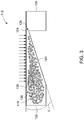
- FIG. 2 is a perspective view of an exemplary evaporator 112 that may be used in power converter 104 of power generation system 100 (each shown in FIG. 1 ), and FIG. 3 is a cutaway side view of evaporator 112.
- evaporator 112 includes a supply housing 120, a receiving housing 122, and an expansion housing 124 extending between supply housing 120 and receiving housing 122.
- Expansion housing 124 includes a flow inlet 126 defined at supply housing 120 and a flow outlet 128 defined at receiving housing 122.
- supply housing 120 includes a first flow opening 130 defined therein and receiving housing 122 includes a second flow opening 132 defined therein.
- supply housing 120 and receiving housing 122 are oriented such that first flow opening 130 and second flow opening 132 are oppositely faced relative to each other.
- multiple evaporators 112 are coupled together end-to-end at first flow opening 130 and second flow opening 132 to increase the cooling capacity of heat removal assembly 110.
- the multiple evaporators 112 are formed integrally as a unitary structure.
- at least a portion of each of supply housing 120 and receiving housing 122 are oriented oppositely perpendicular relative to expansion housing 124 such that multiple evaporators 112 are vertically stackable on top of each other.
- working fluid 118 is channeled through heat removal assembly 110 (each shown in FIG. 1 ). More specifically, working fluid 118 is channeled into supply housing 120 through first flow opening 130 from condenser 114 (shown in FIG. 1 ), and supply housing 120 supplies expansion housing 124 with working fluid 118 through flow inlet 126. In addition, working fluid 118 discharged from expansion housing 124 through flow outlet 128 is received within receiving housing 122, and receiving housing 122 discharges working fluid 118 towards condenser 114 through second flow opening 132.
- expansion housing 124 is thermally coupled to a heat load 134, such as electronic components 108 of power converter 104 (each shown in FIG. 1 ). As such, heat transferred from heat load 134 facilitates vaporizing working fluid 118 channeled through expansion housing 124 such that heat is dissipated from heat load 134.
- expansion housing 124 has an asymmetric design such that flow inlet 126 is sized smaller than flow outlet 128. More specifically, expansion housing 124 is designed such that flow inlet 126 has a smaller cross-sectional area than flow outlet 128.
- expansion housing 124 includes an interior 136 that progressively increases in size (i.e., increases in volumetric capacity) from flow inlet 126 towards flow outlet 128.
- heat transferred from heat load 134 facilitates vaporizing working fluid 118 channeled through expansion housing 124. When vaporized from a liquid state, the volume of working fluid 118 increases in accordance with the Ideal Gas Law.
- expansion housing 124 facilitates accommodating the increased volume of working fluid 118 channeled through expansion housing 124 such that the vaporized working fluid 118 is forced towards flow outlet 128 and backflow is restricted through flow inlet 126.
- a ratio of a cross-sectional area of flow inlet 126 relative to a cross-sectional area of flow outlet 128 is less than or equal to about 0.5.
- interior 136 of expansion housing 124 is defined between a first flat surface 138 and a second flat surface 140 that each extend between flow inlet 126 and flow outlet 128.
- First flat surface 138 and second flat surface 140 are angled relative to each other by an angle ⁇ .
- Angle ⁇ is defined within a range between about 0 degrees and about 90 degrees. Angling first flat surface 138 and second flat surface 140 relative to each other facilitates progressively increasing the size of interior 136 from flow inlet 126 towards flow outlet 128.
- second flat surface 140 has a stepped design for increasing the size of interior 136 at predetermined intervals from flow inlet 126 towards flow outlet 128.
- FIG. 4 is a perspective illustration of an alternative evaporator 142 that may be used in power converter 104 of the power generation system 100 (each shown in FIG. 1 ).
- evaporator 142 includes a plurality of expansion housings 124 arranged in parallel between supply housing 120 and receiving housing 122. As such, the cooling capacity of evaporator 142 is greater than evaporator 112 (shown in FIG. 2 ).
- supply housing 120 and receiving housing 122 extend between each of the plurality of expansion housings 124. As such, supply housing 120 and receiving housing 122 act as manifolds for simultaneously supplying and receiving working fluid from the plurality of expansion housings 124 during operation of power converter 104.
- An exemplary technical effect of the system and methods described herein includes at least one of: (a) restricting backflow in an evaporator of a two-phase liquid cooling system; (b) reducing the likelihood of dry out in the two-phase liquid cooling system; (c) increasing the operability of a heat removal assembly incorporating the evaporator described herein; and (d) reducing flow oscillations of expanding fluid discharged from the evaporator.
- Exemplary embodiments of a heat removal assembly and related components are described above in detail.
- the system is not limited to the specific embodiments described herein, but rather, components of systems and/or steps of the methods may be utilized independently and separately from other components and/or steps described herein.
- the configuration of components described herein may also be used in combination with other processes, and is not limited to practice with only power generation plants and related methods as described herein. Rather, the exemplary embodiment can be implemented and utilized in connection with many applications where dissipating heat from a heat load is desired.
Landscapes
- Engineering & Computer Science (AREA)
- Microelectronics & Electronic Packaging (AREA)
- Physics & Mathematics (AREA)
- Thermal Sciences (AREA)
- Cooling Or The Like Of Semiconductors Or Solid State Devices (AREA)
- Cooling Or The Like Of Electrical Apparatus (AREA)
Claims (5)
- Wärmeabfuhranordnung (110) zur Verwendung mit einem Leistungswandler (104), wobei die Wärmeabfuhranordnung (110) umfasst:einen Kondensator (114); undeinen Verdampfer (112), der in Strömungsverbindung mit dem Kondensator (114) gekoppelt ist, wobei der Verdampfer (112) konfiguriert ist, um Arbeitsfluid (118) dazwischen zu leiten, wobei der Verdampfer (112) umfasst:ein Zufuhrgehäuse (120), das eine erste Strömungsöffnung (130) einschließt;ein Aufnahmegehäuse (122), das eine zweite Strömungsöffnung (132) einschließt, wobei das Zufuhrgehäuse (120) und das Aufnahmegehäuse (122) so ausgerichtet sind, dass die erste Strömungsöffnung (130) und die zweite Strömungsöffnung (132) relativ zueinander gegenüberliegend angeordnet sind; undmindestens ein Expansionsgehäuse (124), das sich zwischen dem Zufuhrgehäuse (120) und dem Aufnahmegehäuse (122) erstreckt, wobei das mindestens eine Expansionsgehäuse (124) einen Strömungseinlass (126), der an dem Zufuhrgehäuse (120) definiert ist und durch den das Arbeitsfluid (118) vom Zufuhrgehäuse (120) dem Expansionsgehäuse (124) zugeführt wird, und einen Strömungsauslass (128) umfasst, der an dem Aufnahmegehäuse (122) definiert ist und durch den das Arbeitsfluid (118) aus dem Expansionsgehäuse (124) zu dem Aufnahmegehäuse (122) abgegeben wird, wobei der Strömungseinlass (126) im Querschnitt kleiner als der Strömungsauslass (128) ist;wobei der Verdampfer (112) konfiguriert ist, um das Arbeitsfluid (118) von dem Kondensator (114) durch die erste Strömungsöffnung (130) in das Zufuhrgehäuse (120) zu leiten und das Arbeitsfluid (118) in Richtung des Kondensators (114) durch die zweite Strömungsöffnung (132) abzugeben;wobei das mindestens eine Expansionsgehäuse (124) einen Innenraum (136) umfasst, dessen Größe vom Strömungseinlass (126) zum Strömungsauslass (128) progressiv zunimmt;dadurch gekennzeichnet, dassdas mindestens eine Expansionsgehäuse (124) konfiguriert ist, um thermisch mit einer Wärmelast (134) gekoppelt zu werden, so dass die von der Wärmelast (134) übertragene Wärme das durch das mindestens eine Expansionsgehäuse (124) geleitete Arbeitsfluid (118) mindestens teilweise verdampft.
- Wärmeabfuhranordnung (110) nach Anspruch 1, wobei ein Verhältnis einer Querschnittsfläche des Strömungseinlasses (126) zu einer Querschnittsfläche des Strömungsauslasses (128) kleiner oder gleich ungefähr 0,5 ist.
- Wärmeabfuhranordnung (110) nach Anspruch 1, wobei das Expansionsgehäuse (124) einen Innenraum (136) umfasst, der durch eine erste flache Oberfläche (138) und eine zweite flache Oberfläche (140) definiert ist, die sich jeweils zwischen dem Strömungseinlass (126) und dem Strömungsauslass (128) erstrecken, wobei die erste flache Oberfläche (138) und die zweite flache Oberfläche (140) relativ zueinander abgewinkelt sind.
- Wärmeabfuhranordnung (110) nach Anspruch 1, wobei der Verdampfer (112) eine Vielzahl von Expansionsgehäusen (124) umfasst, die parallel zwischen dem Zufuhrgehäuse (120) und dem Aufnahmegehäuse (122) angeordnet sind.
- Leistungswandler (104), umfassend:eine Vielzahl von elektronischen Komponenten (108); undeine Wärmeabfuhranordnung (110) nach einem vorstehenden Anspruch;wobei die Vielzahl von elektronischen Komponenten (108) thermisch mit dem mindestens einen Expansionsgehäuse (124) als thermische Last gekoppelt ist, so dass die von den elektronischen Komponenten (108) übertragene Wärme das durch das mindestens eine Expansionsgehäuse (124) geleitete Arbeitsfluid (118) mindestens teilweise verdampft.
Applications Claiming Priority (2)
| Application Number | Priority Date | Filing Date | Title |
|---|---|---|---|
| US15/231,136 US9894815B1 (en) | 2016-08-08 | 2016-08-08 | Heat removal assembly for use with a power converter |
| PCT/US2017/040728 WO2018031147A1 (en) | 2016-08-08 | 2017-07-05 | Heat removal assembly for use with a power converter |
Publications (2)
| Publication Number | Publication Date |
|---|---|
| EP3498063A1 EP3498063A1 (de) | 2019-06-19 |
| EP3498063B1 true EP3498063B1 (de) | 2021-03-31 |
Family
ID=59523221
Family Applications (1)
| Application Number | Title | Priority Date | Filing Date |
|---|---|---|---|
| EP17748964.8A Active EP3498063B1 (de) | 2016-08-08 | 2017-07-05 | Wärmeabfuhranordnung zur verwendung mit einem stromwandler |
Country Status (5)
| Country | Link |
|---|---|
| US (1) | US9894815B1 (de) |
| EP (1) | EP3498063B1 (de) |
| CN (1) | CN109565946B (de) |
| ES (1) | ES2877812T3 (de) |
| WO (1) | WO2018031147A1 (de) |
Families Citing this family (1)
| Publication number | Priority date | Publication date | Assignee | Title |
|---|---|---|---|---|
| US10104814B2 (en) | 2014-11-03 | 2018-10-16 | General Electric Company | System and method for cooling electrical components of a power converter |
Citations (1)
| Publication number | Priority date | Publication date | Assignee | Title |
|---|---|---|---|---|
| WO2000070289A1 (en) * | 1999-05-18 | 2000-11-23 | 3M Innovative Properties Company | Two-phase heat transfer without de-gassing |
Family Cites Families (68)
| Publication number | Priority date | Publication date | Assignee | Title |
|---|---|---|---|---|
| US6152215A (en) | 1998-12-23 | 2000-11-28 | Sundstrand Corporation | High intensity cooler |
| US6993926B2 (en) | 2001-04-26 | 2006-02-07 | Rini Technologies, Inc. | Method and apparatus for high heat flux heat transfer |
| US6498725B2 (en) | 2001-05-01 | 2002-12-24 | Mainstream Engineering Corporation | Method and two-phase spray cooling apparatus |
| US6536510B2 (en) | 2001-07-10 | 2003-03-25 | Thermal Corp. | Thermal bus for cabinets housing high power electronics equipment |
| US7073567B2 (en) * | 2001-08-14 | 2006-07-11 | Global Cooling Bv | Condenser evaporator and cooling device |
| NO320664B1 (no) | 2001-12-19 | 2006-01-16 | Sinvent As | System for oppvarming og kjoling av kjoretoy |
| WO2003063241A2 (en) | 2002-01-22 | 2003-07-31 | Rini Technologies, Inc. | Method and apparatus for high heat flux heat transfer |
| US6772603B2 (en) | 2002-12-20 | 2004-08-10 | Ut-Battelle, Llc | Methods and apparatus for thermal management of vehicle systems and components |
| US7013955B2 (en) | 2003-07-28 | 2006-03-21 | Thermal Corp. | Flexible loop thermosyphon |
| US6993924B2 (en) | 2004-02-12 | 2006-02-07 | Ut-Battelle, Llc | Floating loop system for cooling integrated motors and inverters using hot liquid refrigerant |
| US7958935B2 (en) | 2004-03-31 | 2011-06-14 | Belits Computer Systems, Inc. | Low-profile thermosyphon-based cooling system for computers and other electronic devices |
| DE102004028037B4 (de) * | 2004-06-09 | 2009-04-02 | Airbus Deutschland Gmbh | Verdampferanordnung für ein Klimasystem eines Flugzeugs |
| FR2877078B1 (fr) | 2004-10-25 | 2007-02-02 | Snecma Moteurs Sa | Systeme energetique mettant en oeuvre du gaz naturel stocke sous forme liquide et des machines thermoelectriques |
| US7848624B1 (en) | 2004-10-25 | 2010-12-07 | Alliant Techsystems Inc. | Evaporator for use in a heat transfer system |
| US7266969B2 (en) | 2005-01-06 | 2007-09-11 | Ut-Batelle, Llc | Refrigerant directly cooled capacitors |
| US7273357B2 (en) | 2005-08-10 | 2007-09-25 | Mitsubishi Heavy Industries, Ltd. | Control device for electric compressor |
| US20070095087A1 (en) | 2005-11-01 | 2007-05-03 | Wilson Michael J | Vapor compression cooling system for cooling electronics |
| EP1863085A3 (de) | 2006-06-01 | 2008-03-05 | Abb Research Ltd. | Zweiphasiges Kühlsystem zum Kühlen von Leistungselektronikbauteilen |
| US20080060371A1 (en) | 2006-09-08 | 2008-03-13 | John David Jude | Compact refrigeration apparatus |
| ATE519360T1 (de) | 2006-12-23 | 2011-08-15 | Abb Research Ltd | Flexible heizkabelvorrichtung |
| US8056615B2 (en) | 2007-01-17 | 2011-11-15 | Hamilton Sundstrand Corporation | Evaporative compact high intensity cooler |
| DE602008002507D1 (de) | 2007-08-27 | 2010-10-28 | Abb Research Ltd | Wärmetauscher für Komponenten der Leistungselektronik |
| EP2119993A1 (de) | 2008-05-14 | 2009-11-18 | ABB Research Ltd. | Zweiphasiger Kühlkreislauf |
| US20120087088A1 (en) | 2008-08-05 | 2012-04-12 | Pipeline Micro, Inc. | Microscale heat transfer systems |
| US8353174B1 (en) | 2008-10-03 | 2013-01-15 | Johnson Controls Technology Company | Control method for vapor compression system |
| JP5757086B2 (ja) * | 2008-10-29 | 2015-07-29 | 日本電気株式会社 | 冷却構造及び電子機器並びに冷却方法 |
| DE202009019071U1 (de) | 2009-02-17 | 2016-03-17 | Gudrun Stemke | Verdampfer und Kühleinrichtung unter Verwendung derartiger Verdampfer |
| FR2945337B1 (fr) | 2009-05-06 | 2012-05-25 | Commissariat Energie Atomique | Dispositif d'echange thermique a coefficient d'echange thermique augmente et procede de realisation d'un tel dispositif |
| US20120186290A1 (en) | 2009-05-29 | 2012-07-26 | Jeremy Charles Howes | Pumped loop driven vapor compression cooling system |
| US8976526B2 (en) | 2009-06-30 | 2015-03-10 | Teco-Westinghouse Motor Company | Providing a cooling system for a medium voltage drive system |
| ATE554643T1 (de) | 2009-08-05 | 2012-05-15 | Abb Research Ltd | Verdampfer und kühlkreis |
| EP2284846A1 (de) | 2009-08-13 | 2011-02-16 | ABB Research Ltd. | Trockentransformator, der mittels eines kompakten Thermosiphon-Luft-zu-Luft-Wärmetauschers gekühlt wird |
| WO2011035943A2 (en) | 2009-09-28 | 2011-03-31 | Abb Research Ltd | Cooling module for cooling electronic components |
| WO2011044445A1 (en) | 2009-10-09 | 2011-04-14 | Parker Hannifin Corporation | Two phase cooling pump module |
| DK2543242T3 (da) | 2010-03-03 | 2014-06-10 | Parker Hannificn Corp | Kondensator-bypass til tofaset elektronisk kølesystem |
| KR101205715B1 (ko) | 2010-05-24 | 2012-11-28 | 한국과학기술원 | 플랫형 열 분산기 및 그 제조 방법 |
| US20120024500A1 (en) | 2010-06-18 | 2012-02-02 | Gatekeeper Laboratories Pte Ltd | Thermosyphon for cooling electronic components |
| JP5401419B2 (ja) * | 2010-08-31 | 2014-01-29 | 株式会社日立製作所 | 鉄道車両用電力変換装置 |
| DE102010042127B4 (de) | 2010-10-07 | 2020-09-17 | Audi Ag | Kältemittelkreislauf einer Klimaanlage eines Kraftfahrzeuges |
| US9879891B2 (en) | 2011-02-17 | 2018-01-30 | Mahle International Gmbh | Unitary heat pump air conditioner having a compressed vapor diversion loop |
| US20120227429A1 (en) | 2011-03-10 | 2012-09-13 | Timothy Louvar | Cooling system |
| WO2012131709A1 (en) | 2011-03-28 | 2012-10-04 | Praveen Shankar JAMBHOLKAR | Adaptive speed control of compressor motor |
| CN103460828B (zh) | 2011-04-04 | 2016-03-23 | 丹佛斯硅动力股份有限公司 | 用于功率模块的冷却系统 |
| US20120312037A1 (en) | 2011-06-08 | 2012-12-13 | Hamilton Sundstrand Corporation | Vapor cycle system with de-superheater |
| US20150257303A1 (en) | 2011-06-27 | 2015-09-10 | Ebullient, Llc | Method of cooling multiple processors using series-connected heat sinks |
| US9807908B2 (en) | 2011-06-30 | 2017-10-31 | Parker-Hannifin Corporation | Pumped liquid cooling system using a phase change fluid with additional subambient cooling |
| WO2013023279A1 (en) | 2011-08-12 | 2013-02-21 | Captherm Systems Inc. | Two-phase heat transfer apparatus |
| EP2568789B1 (de) | 2011-09-06 | 2014-04-16 | ABB Research Ltd. | Wärmetauscher |
| AU2012232967B2 (en) | 2011-10-31 | 2015-01-15 | Abb Technology Ag | Cabinet with modules having a thermosiphon cooler arrangement |
| AU2012232968B2 (en) * | 2011-10-31 | 2014-11-13 | Abb Technology Ag | Thermosiphon cooler arrangement in modules with electric and/or electronic components |
| US8711565B2 (en) | 2011-11-02 | 2014-04-29 | General Electric Company | System and method for operating an electric power converter |
| DE102011118873A1 (de) | 2011-11-18 | 2013-05-23 | Airbus Operations Gmbh | Fahrzeug mit einem Kühlsystem zum Kühlen und Verfahren zum Kühlen in einem Fahrzeug |
| CN104040278A (zh) | 2012-01-04 | 2014-09-10 | 日本电气株式会社 | 冷却装置和使用该冷却装置的电子装置 |
| US9179575B1 (en) | 2012-03-13 | 2015-11-03 | Rockwell Collins, Inc. | MEMS based device for phase-change autonomous transport of heat (PATH) |
| EP2645040B1 (de) | 2012-03-28 | 2017-06-21 | ABB Research Ltd. | Wärmetauscher für Traktionsstromrichter |
| EP2677261B1 (de) * | 2012-06-20 | 2018-10-10 | ABB Schweiz AG | Zweiphasiges Kühlsystem für elektronische Bauteile |
| DE102013105747B4 (de) | 2012-07-18 | 2022-06-09 | Hanon Systems | Vorrichtungen zur Wärmeverteilung in einem Kraftfahrzeug |
| EP2703763A1 (de) | 2012-09-03 | 2014-03-05 | ABB Technology AG | Verdampfer mit integriertem Vorwärmer zur Leistungselektronikkühlung |
| WO2014048680A1 (en) | 2012-09-26 | 2014-04-03 | Abb Technology Ag | Isolating conduit for a dielectric fluid |
| JPWO2014049805A1 (ja) * | 2012-09-28 | 2016-08-22 | 株式会社日立製作所 | 冷却システム、及びそれを用いた電気機器 |
| EP2734020B1 (de) | 2012-11-19 | 2017-07-12 | ABB Schweiz AG | Kühlanordnung mit einem zweiphasigen Wärmesyphon zum Kühlen einer Mehrzahl elektrischer Vorrichtungen |
| US9835363B2 (en) | 2013-01-14 | 2017-12-05 | Massachusetts Institute Of Technology | Evaporative heat transfer system |
| US20140251585A1 (en) | 2013-03-05 | 2014-09-11 | The Boeing Company | Micro-lattice Cross-flow Heat Exchangers for Aircraft |
| US9363930B2 (en) | 2013-03-11 | 2016-06-07 | Teco-Westinghouse Motor Company | Passive two phase cooling solution for low, medium and high voltage drive systems |
| US9153374B2 (en) | 2013-06-28 | 2015-10-06 | Teco-Westinghouse Motor Company | Cooling arrangements for drive systems |
| ES2629264T3 (es) | 2013-09-16 | 2017-08-08 | Phononic Devices, Inc. | Sistemas caloportadores mejorados para enfriar cámaras y superficies |
| US10104814B2 (en) | 2014-11-03 | 2018-10-16 | General Electric Company | System and method for cooling electrical components of a power converter |
| DK3115729T3 (en) * | 2015-07-09 | 2019-04-01 | Abb Schweiz Ag | HEAT EXCHANGE |
-
2016
- 2016-08-08 US US15/231,136 patent/US9894815B1/en active Active
-
2017
- 2017-07-05 CN CN201780047963.9A patent/CN109565946B/zh not_active Expired - Fee Related
- 2017-07-05 EP EP17748964.8A patent/EP3498063B1/de active Active
- 2017-07-05 WO PCT/US2017/040728 patent/WO2018031147A1/en not_active Ceased
- 2017-07-05 ES ES17748964T patent/ES2877812T3/es active Active
Patent Citations (1)
| Publication number | Priority date | Publication date | Assignee | Title |
|---|---|---|---|---|
| WO2000070289A1 (en) * | 1999-05-18 | 2000-11-23 | 3M Innovative Properties Company | Two-phase heat transfer without de-gassing |
Also Published As
| Publication number | Publication date |
|---|---|
| CN109565946B (zh) | 2020-11-27 |
| WO2018031147A1 (en) | 2018-02-15 |
| ES2877812T3 (es) | 2021-11-17 |
| US20180042145A1 (en) | 2018-02-08 |
| CN109565946A (zh) | 2019-04-02 |
| EP3498063A1 (de) | 2019-06-19 |
| US9894815B1 (en) | 2018-02-13 |
Similar Documents
| Publication | Publication Date | Title |
|---|---|---|
| US11997839B2 (en) | Heat dissipation system and an associated method thereof | |
| Kazem et al. | Enhancement of photovoltaic module performance using passive cooling (Fins): A comprehensive review | |
| Sangwongwanich et al. | On the impacts of PV array sizing on the inverter reliability and lifetime | |
| CN103094226B (zh) | 用于操作电功率转换器的系统和方法 | |
| US12206080B2 (en) | Modular energy storage system with battery cooling | |
| KR102478570B1 (ko) | 파워 스택 | |
| Stallon et al. | High efficient module of boost converter in PV module | |
| US20110308576A1 (en) | Hybrid photovoltaic system and method thereof | |
| Blaabjerg et al. | Flexible power control of photovoltaic systems | |
| US9894815B1 (en) | Heat removal assembly for use with a power converter | |
| US10590916B2 (en) | Multisiphon passive cooling system | |
| US20120273026A1 (en) | Hybrid solar concentration device | |
| US11051428B2 (en) | Oscillating heat pipe integrated thermal management system for power electronics | |
| Mosobi et al. | Performance analysis of hybrid solar-wind-microhydro system in islanded mode | |
| Herrera et al. | Implementing multilevel inverters and multiport DC-DC converters for microgrids | |
| US20200227936A1 (en) | Power Continuity Apparatus | |
| Mondol | Sizing of grid-connected photovoltaic systems | |
| US20240215201A1 (en) | Power conversion system | |
| Liu et al. | Research on cooling technology of solar cell | |
| Ishibashi et al. | Control Method of Energy Storage System to Improve Output Power of PCS | |
| EP3517777A1 (de) | Passivkühlungssystem mit multisiphon | |
| Babu et al. | Performance analysis of flat plate hybrid PV/thermal configurations | |
| Sekar et al. | Hybrid Energy Sources using Current Fed Inverter for High Gain in Single Phase to AC Loads | |
| Singh et al. | Minimize THD of Variable Load Conversion based Wind Energy System using Three-phase Converter | |
| CHANDRASEKHAR | OPTIMIZED DESIGN AND ANALYSIS OF MULTILEVEL BOOST INVERTER FOR HIGH-FREQUENCY OPERATION WITH MINIMAL COMPONENT COUNT |
Legal Events
| Date | Code | Title | Description |
|---|---|---|---|
| STAA | Information on the status of an ep patent application or granted ep patent |
Free format text: STATUS: UNKNOWN |
|
| STAA | Information on the status of an ep patent application or granted ep patent |
Free format text: STATUS: THE INTERNATIONAL PUBLICATION HAS BEEN MADE |
|
| PUAI | Public reference made under article 153(3) epc to a published international application that has entered the european phase |
Free format text: ORIGINAL CODE: 0009012 |
|
| STAA | Information on the status of an ep patent application or granted ep patent |
Free format text: STATUS: REQUEST FOR EXAMINATION WAS MADE |
|
| 17P | Request for examination filed |
Effective date: 20190125 |
|
| AK | Designated contracting states |
Kind code of ref document: A1 Designated state(s): AL AT BE BG CH CY CZ DE DK EE ES FI FR GB GR HR HU IE IS IT LI LT LU LV MC MK MT NL NO PL PT RO RS SE SI SK SM TR |
|
| AX | Request for extension of the european patent |
Extension state: BA ME |
|
| DAV | Request for validation of the european patent (deleted) | ||
| DAX | Request for extension of the european patent (deleted) | ||
| STAA | Information on the status of an ep patent application or granted ep patent |
Free format text: STATUS: EXAMINATION IS IN PROGRESS |
|
| 17Q | First examination report despatched |
Effective date: 20200422 |
|
| GRAP | Despatch of communication of intention to grant a patent |
Free format text: ORIGINAL CODE: EPIDOSNIGR1 |
|
| STAA | Information on the status of an ep patent application or granted ep patent |
Free format text: STATUS: GRANT OF PATENT IS INTENDED |
|
| INTG | Intention to grant announced |
Effective date: 20201030 |
|
| GRAS | Grant fee paid |
Free format text: ORIGINAL CODE: EPIDOSNIGR3 |
|
| GRAA | (expected) grant |
Free format text: ORIGINAL CODE: 0009210 |
|
| STAA | Information on the status of an ep patent application or granted ep patent |
Free format text: STATUS: THE PATENT HAS BEEN GRANTED |
|
| AK | Designated contracting states |
Kind code of ref document: B1 Designated state(s): AL AT BE BG CH CY CZ DE DK EE ES FI FR GB GR HR HU IE IS IT LI LT LU LV MC MK MT NL NO PL PT RO RS SE SI SK SM TR |
|
| REG | Reference to a national code |
Ref country code: GB Ref legal event code: FG4D Ref country code: CH Ref legal event code: EP |
|
| REG | Reference to a national code |
Ref country code: AT Ref legal event code: REF Ref document number: 1378462 Country of ref document: AT Kind code of ref document: T Effective date: 20210415 |
|
| REG | Reference to a national code |
Ref country code: DE Ref legal event code: R096 Ref document number: 602017035710 Country of ref document: DE |
|
| REG | Reference to a national code |
Ref country code: IE Ref legal event code: FG4D |
|
| REG | Reference to a national code |
Ref country code: LT Ref legal event code: MG9D |
|
| PG25 | Lapsed in a contracting state [announced via postgrant information from national office to epo] |
Ref country code: BG Free format text: LAPSE BECAUSE OF FAILURE TO SUBMIT A TRANSLATION OF THE DESCRIPTION OR TO PAY THE FEE WITHIN THE PRESCRIBED TIME-LIMIT Effective date: 20210630 Ref country code: NO Free format text: LAPSE BECAUSE OF FAILURE TO SUBMIT A TRANSLATION OF THE DESCRIPTION OR TO PAY THE FEE WITHIN THE PRESCRIBED TIME-LIMIT Effective date: 20210630 Ref country code: HR Free format text: LAPSE BECAUSE OF FAILURE TO SUBMIT A TRANSLATION OF THE DESCRIPTION OR TO PAY THE FEE WITHIN THE PRESCRIBED TIME-LIMIT Effective date: 20210331 Ref country code: FI Free format text: LAPSE BECAUSE OF FAILURE TO SUBMIT A TRANSLATION OF THE DESCRIPTION OR TO PAY THE FEE WITHIN THE PRESCRIBED TIME-LIMIT Effective date: 20210331 |
|
| PG25 | Lapsed in a contracting state [announced via postgrant information from national office to epo] |
Ref country code: RS Free format text: LAPSE BECAUSE OF FAILURE TO SUBMIT A TRANSLATION OF THE DESCRIPTION OR TO PAY THE FEE WITHIN THE PRESCRIBED TIME-LIMIT Effective date: 20210331 Ref country code: LV Free format text: LAPSE BECAUSE OF FAILURE TO SUBMIT A TRANSLATION OF THE DESCRIPTION OR TO PAY THE FEE WITHIN THE PRESCRIBED TIME-LIMIT Effective date: 20210331 Ref country code: SE Free format text: LAPSE BECAUSE OF FAILURE TO SUBMIT A TRANSLATION OF THE DESCRIPTION OR TO PAY THE FEE WITHIN THE PRESCRIBED TIME-LIMIT Effective date: 20210331 |
|
| REG | Reference to a national code |
Ref country code: NL Ref legal event code: MP Effective date: 20210331 |
|
| REG | Reference to a national code |
Ref country code: AT Ref legal event code: MK05 Ref document number: 1378462 Country of ref document: AT Kind code of ref document: T Effective date: 20210331 |
|
| PG25 | Lapsed in a contracting state [announced via postgrant information from national office to epo] |
Ref country code: EE Free format text: LAPSE BECAUSE OF FAILURE TO SUBMIT A TRANSLATION OF THE DESCRIPTION OR TO PAY THE FEE WITHIN THE PRESCRIBED TIME-LIMIT Effective date: 20210331 Ref country code: CZ Free format text: LAPSE BECAUSE OF FAILURE TO SUBMIT A TRANSLATION OF THE DESCRIPTION OR TO PAY THE FEE WITHIN THE PRESCRIBED TIME-LIMIT Effective date: 20210331 Ref country code: LT Free format text: LAPSE BECAUSE OF FAILURE TO SUBMIT A TRANSLATION OF THE DESCRIPTION OR TO PAY THE FEE WITHIN THE PRESCRIBED TIME-LIMIT Effective date: 20210331 Ref country code: AT Free format text: LAPSE BECAUSE OF FAILURE TO SUBMIT A TRANSLATION OF THE DESCRIPTION OR TO PAY THE FEE WITHIN THE PRESCRIBED TIME-LIMIT Effective date: 20210331 Ref country code: SM Free format text: LAPSE BECAUSE OF FAILURE TO SUBMIT A TRANSLATION OF THE DESCRIPTION OR TO PAY THE FEE WITHIN THE PRESCRIBED TIME-LIMIT Effective date: 20210331 Ref country code: NL Free format text: LAPSE BECAUSE OF FAILURE TO SUBMIT A TRANSLATION OF THE DESCRIPTION OR TO PAY THE FEE WITHIN THE PRESCRIBED TIME-LIMIT Effective date: 20210331 |
|
| REG | Reference to a national code |
Ref country code: ES Ref legal event code: FG2A Ref document number: 2877812 Country of ref document: ES Kind code of ref document: T3 Effective date: 20211117 |
|
| PG25 | Lapsed in a contracting state [announced via postgrant information from national office to epo] |
Ref country code: IS Free format text: LAPSE BECAUSE OF FAILURE TO SUBMIT A TRANSLATION OF THE DESCRIPTION OR TO PAY THE FEE WITHIN THE PRESCRIBED TIME-LIMIT Effective date: 20210731 Ref country code: RO Free format text: LAPSE BECAUSE OF FAILURE TO SUBMIT A TRANSLATION OF THE DESCRIPTION OR TO PAY THE FEE WITHIN THE PRESCRIBED TIME-LIMIT Effective date: 20210331 Ref country code: SK Free format text: LAPSE BECAUSE OF FAILURE TO SUBMIT A TRANSLATION OF THE DESCRIPTION OR TO PAY THE FEE WITHIN THE PRESCRIBED TIME-LIMIT Effective date: 20210331 Ref country code: PT Free format text: LAPSE BECAUSE OF FAILURE TO SUBMIT A TRANSLATION OF THE DESCRIPTION OR TO PAY THE FEE WITHIN THE PRESCRIBED TIME-LIMIT Effective date: 20210802 Ref country code: PL Free format text: LAPSE BECAUSE OF FAILURE TO SUBMIT A TRANSLATION OF THE DESCRIPTION OR TO PAY THE FEE WITHIN THE PRESCRIBED TIME-LIMIT Effective date: 20210331 |
|
| REG | Reference to a national code |
Ref country code: DE Ref legal event code: R097 Ref document number: 602017035710 Country of ref document: DE |
|
| PG25 | Lapsed in a contracting state [announced via postgrant information from national office to epo] |
Ref country code: AL Free format text: LAPSE BECAUSE OF FAILURE TO SUBMIT A TRANSLATION OF THE DESCRIPTION OR TO PAY THE FEE WITHIN THE PRESCRIBED TIME-LIMIT Effective date: 20210331 Ref country code: DK Free format text: LAPSE BECAUSE OF FAILURE TO SUBMIT A TRANSLATION OF THE DESCRIPTION OR TO PAY THE FEE WITHIN THE PRESCRIBED TIME-LIMIT Effective date: 20210331 |
|
| PLBE | No opposition filed within time limit |
Free format text: ORIGINAL CODE: 0009261 |
|
| STAA | Information on the status of an ep patent application or granted ep patent |
Free format text: STATUS: NO OPPOSITION FILED WITHIN TIME LIMIT |
|
| REG | Reference to a national code |
Ref country code: CH Ref legal event code: PL |
|
| 26N | No opposition filed |
Effective date: 20220104 |
|
| PG25 | Lapsed in a contracting state [announced via postgrant information from national office to epo] |
Ref country code: MC Free format text: LAPSE BECAUSE OF FAILURE TO SUBMIT A TRANSLATION OF THE DESCRIPTION OR TO PAY THE FEE WITHIN THE PRESCRIBED TIME-LIMIT Effective date: 20210331 |
|
| REG | Reference to a national code |
Ref country code: BE Ref legal event code: MM Effective date: 20210731 |
|
| PG25 | Lapsed in a contracting state [announced via postgrant information from national office to epo] |
Ref country code: LI Free format text: LAPSE BECAUSE OF NON-PAYMENT OF DUE FEES Effective date: 20210731 Ref country code: CH Free format text: LAPSE BECAUSE OF NON-PAYMENT OF DUE FEES Effective date: 20210731 |
|
| PG25 | Lapsed in a contracting state [announced via postgrant information from national office to epo] |
Ref country code: IS Free format text: LAPSE BECAUSE OF FAILURE TO SUBMIT A TRANSLATION OF THE DESCRIPTION OR TO PAY THE FEE WITHIN THE PRESCRIBED TIME-LIMIT Effective date: 20210731 Ref country code: LU Free format text: LAPSE BECAUSE OF NON-PAYMENT OF DUE FEES Effective date: 20210705 |
|
| PG25 | Lapsed in a contracting state [announced via postgrant information from national office to epo] |
Ref country code: IT Free format text: LAPSE BECAUSE OF FAILURE TO SUBMIT A TRANSLATION OF THE DESCRIPTION OR TO PAY THE FEE WITHIN THE PRESCRIBED TIME-LIMIT Effective date: 20210331 Ref country code: BE Free format text: LAPSE BECAUSE OF NON-PAYMENT OF DUE FEES Effective date: 20210731 |
|
| P01 | Opt-out of the competence of the unified patent court (upc) registered |
Effective date: 20230522 |
|
| PG25 | Lapsed in a contracting state [announced via postgrant information from national office to epo] |
Ref country code: CY Free format text: LAPSE BECAUSE OF FAILURE TO SUBMIT A TRANSLATION OF THE DESCRIPTION OR TO PAY THE FEE WITHIN THE PRESCRIBED TIME-LIMIT Effective date: 20210331 |
|
| PG25 | Lapsed in a contracting state [announced via postgrant information from national office to epo] |
Ref country code: HU Free format text: LAPSE BECAUSE OF FAILURE TO SUBMIT A TRANSLATION OF THE DESCRIPTION OR TO PAY THE FEE WITHIN THE PRESCRIBED TIME-LIMIT; INVALID AB INITIO Effective date: 20170705 Ref country code: GR Free format text: LAPSE BECAUSE OF FAILURE TO SUBMIT A TRANSLATION OF THE DESCRIPTION OR TO PAY THE FEE WITHIN THE PRESCRIBED TIME-LIMIT Effective date: 20210331 |
|
| REG | Reference to a national code |
Ref country code: DE Ref legal event code: R081 Ref document number: 602017035710 Country of ref document: DE Owner name: GE GRID SOLUTIONS LLC, ATLANTA, US Free format text: FORMER OWNER: GENERAL ELECTRIC COMPANY, SCHENECTADY, NY, US |
|
| REG | Reference to a national code |
Ref country code: GB Ref legal event code: 732E Free format text: REGISTERED BETWEEN 20231207 AND 20231213 |
|
| PG25 | Lapsed in a contracting state [announced via postgrant information from national office to epo] |
Ref country code: MK Free format text: LAPSE BECAUSE OF FAILURE TO SUBMIT A TRANSLATION OF THE DESCRIPTION OR TO PAY THE FEE WITHIN THE PRESCRIBED TIME-LIMIT Effective date: 20210331 |
|
| PG25 | Lapsed in a contracting state [announced via postgrant information from national office to epo] |
Ref country code: TR Free format text: LAPSE BECAUSE OF FAILURE TO SUBMIT A TRANSLATION OF THE DESCRIPTION OR TO PAY THE FEE WITHIN THE PRESCRIBED TIME-LIMIT Effective date: 20210331 |
|
| REG | Reference to a national code |
Ref country code: ES Ref legal event code: PC2A Owner name: GE GRID SOLUTIONS LLC Effective date: 20240809 |
|
| PG25 | Lapsed in a contracting state [announced via postgrant information from national office to epo] |
Ref country code: MT Free format text: LAPSE BECAUSE OF FAILURE TO SUBMIT A TRANSLATION OF THE DESCRIPTION OR TO PAY THE FEE WITHIN THE PRESCRIBED TIME-LIMIT Effective date: 20210331 |
|
| PGFP | Annual fee paid to national office [announced via postgrant information from national office to epo] |
Ref country code: GB Payment date: 20250619 Year of fee payment: 9 |
|
| PGFP | Annual fee paid to national office [announced via postgrant information from national office to epo] |
Ref country code: FR Payment date: 20250620 Year of fee payment: 9 |
|
| PGFP | Annual fee paid to national office [announced via postgrant information from national office to epo] |
Ref country code: IE Payment date: 20250623 Year of fee payment: 9 |
|
| PGFP | Annual fee paid to national office [announced via postgrant information from national office to epo] |
Ref country code: ES Payment date: 20250801 Year of fee payment: 9 |
|
| PGFP | Annual fee paid to national office [announced via postgrant information from national office to epo] |
Ref country code: DE Payment date: 20250620 Year of fee payment: 9 |