EP3497421B1 - Rotationskörper - Google Patents
Rotationskörper Download PDFInfo
- Publication number
- EP3497421B1 EP3497421B1 EP17735460.2A EP17735460A EP3497421B1 EP 3497421 B1 EP3497421 B1 EP 3497421B1 EP 17735460 A EP17735460 A EP 17735460A EP 3497421 B1 EP3497421 B1 EP 3497421B1
- Authority
- EP
- European Patent Office
- Prior art keywords
- groove
- insert
- rotational body
- fastened
- fastening
- Prior art date
- Legal status (The legal status is an assumption and is not a legal conclusion. Google has not performed a legal analysis and makes no representation as to the accuracy of the status listed.)
- Active
Links
Images

Classifications
-
- G—PHYSICS
- G01—MEASURING; TESTING
- G01M—TESTING STATIC OR DYNAMIC BALANCE OF MACHINES OR STRUCTURES; TESTING OF STRUCTURES OR APPARATUS, NOT OTHERWISE PROVIDED FOR
- G01M1/00—Testing static or dynamic balance of machines or structures
- G01M1/30—Compensating imbalance
- G01M1/36—Compensating imbalance by adjusting position of masses built-in the body to be tested
Definitions
- the present invention relates to a rotating body, an electric motor and a method for balancing a rotating body.
- balancing can be positive or negative.
- positive balancing balancing masses are applied, for example by welding, gluing, clamping or screwing weights.
- negative balancing masses are removed, for example by drilling, grinding or milling.
- the US7,656,609 B1 discloses a motor for a hard disk, wherein a rotor has at least three flexible compensating elements.
- the EN 10 2009 003 056 A1 relates to an adjusting device for a rotating body, in particular a fan of a cooling fan of an internal combustion engine or a shaft or a rotor of an electric motor.
- a mass that can rotate about the axis of rotation can be displaced with respect to the axis of rotation.
- the WO 00/65323 relates to a method for balancing and a balancing element.
- a disk-shaped arrangement is provided which has a plurality of projections which can be bent.
- the EN 10 2013 208 456 A1 relates to a balancing element and a method for balancing a clutch, with the aid of which a clutch can be balanced, wherein a balancing element has a shaft for insertion into a housing opening.
- the GB619 587 relates to a rotating body for electrical machines, in which balancing weights can be arranged in grooves formed on the front side.
- the EN 11 52 749 relates to a method for applying balancing weights to the front-side short-circuit rings of rotors of electrical machines, wherein self-fastening parts are pressed into the short-circuit rings made of deformable metal by spreading, which serve either as balancing weights themselves or as carriers for additional balancing weights.
- the EN 10 2012 218 716 A1 relates to a rotor arrangement for an electrical machine and a method for producing a rotor arrangement.
- the invention further comprises an electrical machine with such a rotor arrangement.
- a balancing element is arranged in a recess of the rotor by means of a press fit.
- the US5903967 relates to a method for producing a double cylinder body.
- the WO 15113434 A1 relates to a method for measuring and determining the unbalance of a rotor.
- the EP2924853 A1 relates to a rotor which has a tapered groove on one end face into which one or more groove inserts can be inserted to enable balancing of the rotor.
- a rotary body in particular a rotor for an electric motor, has a groove that runs around at least part of the circumference, wherein at least one insert is or can be fastened in the groove, and wherein the fastening is carried out by deforming or reshaping the at least one insert and/or the groove, wherein the groove is formed in part by an additional component that is fastened to the rotary body on the front side.
- the rotary body is in particular a body that is rotatably mounted or should/can be rotatably mounted.
- the rotary body is also designed to be essentially rotationally symmetrical, for example.
- a rotary body can also mean a body that is not rotationally symmetrical, such as a crankshaft.
- the circumferential groove is preferably a closed groove, in other words a completely circumferential groove, wherein the groove can be arranged on the rotary body both circumferentially and on the front side. If necessary, there are also several grooves that are arranged on the front side and/or on a circumferential side of the rotary body.
- the insert which represents the balancing weight/compensating weight, is now attached without the need for any additional elements such as screws, glue, etc. The insert is therefore advantageously made in one piece.
- the rotary body comprises a front section which extends essentially perpendicular to a rotation axis of the rotary body, wherein the at least one groove is arranged in and/or on the front section.
- this is a circumferentially closed groove in the form of a circular ring.
- the deformation by which the fastening is carried out is expediently an elastic and/or plastic deformation of the insert and/or the groove.
- the fastening is carried out by plastic deformation, in particular by caulking. This achieves a force-fitting and form-fitting connection between the insert and the groove.
- the edge areas of the groove and/or the insert are deformed in such a way that they wedge into each other inseparably. All materials that can be plastically deformed, such as plastics and metals, are suitable for caulking.
- this design also allows different materials to be connected to one another, with the preferred materials for the insert/balancing weight being, for example, zinc, steel, tin, tungsten or plastics that have a sufficiently high density, or a combination of the aforementioned materials.
- the fastening by deformation enables the use of inserts made of a wide variety of materials.
- the balancing mass can be easily determined over the length of the insert or the balancing weight.
- a suitable tool is used for caulking, which has an effective surface that is wider than the groove, so that after the tool surface is in contact with the insert arranged in the groove, the insert and the groove can be caulked/deformed with a blow/impact.
- elastic deformation is also preferred, whereby this particularly means elastic deformation of the groove. It is advisable, for example, to use a tool to slightly lever the groove open, namely to such an extent that the insert can be inserted in a desired location. After the tool is removed, the groove or a side wall of the groove springs back, and the insert is fastened in a force-fitting or form-fitting and/or force-fitting manner.
- the groove is preferably a "built" groove.
- the groove is formed entirely or at least in sections by an additional component which is fastened to the rotating body, in particular on the front side and/or around the circumference.
- This additional component can be, for example, a ring element which is fastened to the rotating body, for example on the front side, in a form-fitting and/or force-fitting manner, in particular screwed on.
- the ring element expediently forms one of the two side flanks of the groove.
- the insert can now preferably be fastened by fastening the ring element to the rotating body. This means that the insert is fastened to a desired position in the groove, whereby the aforementioned ring element is not yet fully fastened, in particular screwed on.
- the insert Only then is it possible for the insert to be arranged within the groove.
- the ring element is expediently fastened at least to such an extent that the insert is held in a desired position.
- the actual fastening is then carried out by screwing the ring element, so that in this embodiment too the insert is advantageously fastened in a form-fitting or form-and-force-fitting manner.
- the elastic or plastic deformations that occur here can be infinitesimally small, but are nevertheless so high that a permanent fastening of the insert in the specified position is possible.
- the at least one insert is a profile wire. It is therefore expediently a very cost-effective component that can simply be cut to the desired length.
- a preferred cross-section of the insert or the profile wire is, for example, square or rectangular. The same applies to the groove.
- the side lengths are in a range of approximately 2-8 mm.
- other cross-sectional shapes can also be provided for the insert/profile wire or the groove, whereby the greatest advantages are always achieved when the simplest possible geometry is used.
- the cross section of the at least one groove is constant. This allows the insert(s) to be attached at any position in the groove, in other words at any angle.
- no groove windows or the like are required, which are necessary for inserting or arranging the insert in the groove.
- the insert can be both inserted and fastened at any point in the groove, with no adjustments being necessary in terms of the shape and geometry of the insert or the groove.
- the groove is therefore advantageously designed or dimensioned completely the same along its circumference or along its length.
- the rotating body is a component of a motor, for example an electric motor or an internal combustion engine.
- the rotating body is a camshaft, a crankshaft of an internal combustion engine or a rotor of an electric motor.
- the invention is also directed to an electric motor, in particular to a high-speed electric motor, such as a current-excited synchronous motor, comprising a (high-speed) rotor which has at least one groove which runs around at least in sections, wherein at least one insert is fastened or can be fastened in the groove, and wherein the fastening takes place by deforming the at least one insert and/or the groove, wherein the groove is formed in sections by an additional component which is fastened to the front of the rotating body.
- the diameters of the (high-speed) rotors are in a range of approximately 110 to 160 mm. Maximum speeds are approximately 30,000 rpm, peak powers approximately 90 to 400 kW.
- the groove which is in particular a closed groove, is expediently formed by an additional element, in particular a support ring, which is attached to the front of the rotor.
- the support ring is a component which is designed to absorb or distribute radial loads from windings arranged on the rotor.
- several such support rings can be provided, which are attached, for example, to both axial ends of the rotor.
- two such additional elements or support rings form one or the groove in between.
- a support ring is designed in such a way that it forms or helps to form at least one side flank of the groove.
- the additional element in particular annular, is a component which is, for example, fastened to the front side on or in the area of the rotor, wherein the fastening is preferably carried out in a form-fitting and/or force-fitting manner, for example via a screw connection.
- the insert is designed and dimensioned such that, before deformation, it projects beyond the groove by approximately 0.5 to 1 mm. After deformation, the insert is expediently essentially flush with the surrounding surface. Alternatively, the insert (before deformation) is also smaller and does not project beyond the groove or is flush with it.
- the rotary body or the insert can have one or more fastening areas, where a fastening area is the area to which a tool for plastic deformation, e.g. a caulking tool, has been or is attached.
- the fastening area is a deformation area, in particular a plastic deformation area.
- two, three or more fastening areas which are essentially round according to one embodiment, are provided.
- a few fastening areas are advantageously sufficient. Above all, it is not necessary to fasten the insert along its entire length, in particular to deform it.
- fastening areas/deformation areas are therefore extremely advantageous, since even longer inserts can be fastened quickly and securely in this way.
- the groove is formed at least in sections by an additional component which is attached to the rotating body.
- the deformation is carried out by attaching the additional component to the rotating body.
- the insert is attached by clamping the additional component, whereby the additional component can be, for example, a support ring of a rotor of an electric motor.
- the additional component can be, for example, a support ring of a rotor of an electric motor.
- the idea here is not limited to a specific type of rotor. or limited to a specific type of electric motor. Rather, the idea can be used for all rotating bodies.
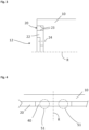
- Fig.1 shows a perspective view of a rotating body 10 which has a rotation axis R.
- the rotating body 10 has a peripheral section 14 and a front section 12.
- An annular groove 20 is arranged in the front section 12.
- the rotating body 10 is, for example, a rotor of an electric motor which is mounted via shaft sections 11. In particular, it can be a high-speed electric motor.
- Fig. 2 now shows a sectional view of a groove 20 of a rotary body 10 in which an insert, in other words a balancing weight, is arranged.
- the section runs transversely to the groove 20.
- the groove 20 is arranged or formed on a front section 12 of the rotary body 10, which has a rotation axis R.
- an insert 40 is not yet fastened in the groove 20. This is only done by deforming the insert and/or the groove 20.
- the insert is expediently fixed by a caulking process, which is implemented, for example, by the tool schematically shown with the reference number 50. By hitting or striking to the right, the tool 50 can deform the insert 40 or the groove 20 in such a way that a permanent positive and non-positive connection is provided.
- Fig.3 is a sectional view of a rotary body 10 which extends along a rotation axis R.
- This also has a groove 20 on a front section 12.
- the groove 20 is formed here by an additional component 22.
- one of the side flanks 23 of the groove 20 is formed by an additional component 22 which is positively and/or non-positively connected to the rotary body, for example by a screw connection 24.
- This makes it possible to attach a balancing weight or insert (not shown here) arranged in the groove 20 by attaching the additional component 22 to the rotary body 10.
- the additional component 22 can be, for example, a support ring, cf. e.g. B. the (outer) projection/support ring arranged radially to the additional component 22, which together with the additional component 22 forms the groove.
- Fig.4 shows a plan view of a groove 20 in which an elongated insert 40 is arranged or fastened.
- the fastening is or was carried out by plastic deformation of the insert 20 or the groove 20 in the area of the fastening areas/deformation areas 51.
- the tool for caulking the insert 40 or the groove 20 was applied at these points.
Landscapes
- Physics & Mathematics (AREA)
- General Physics & Mathematics (AREA)
- Connection Of Motors, Electrical Generators, Mechanical Devices, And The Like (AREA)
Description
- Die vorliegende Erfindung betrifft einen Rotationskörper, einen Elektromotor sowie ein Verfahren zum Wuchten eines Rotationskörpers.
- Jeder um eine feststehende Achse rotierender Körper besitzt eine Unwucht, die zu Vibrationen bzw. Schwingungen, Geräuschen und erhöhtem Verschleiß, bei hohen Drehzahlen sogar zur Zerstörung, führen kann. Wenn die Unwucht zu groß ist, muss ein Ausgleich der Massenverteilung individuell an dem entsprechenden Körper durchgeführt werden. Dieser Ausgleich kann positiv oder negativ erfolgen. Beim positiven Ausgleich werden Ausgleichsmassen aufgetragen, wie z. B. durch Anschweißen, Ankleben, Anklemmen oder Anschrauben von Gewichten. Beim negativen Ausgleich werden Massen abgetragen, z. B. durch Bohren, Schleifen oder Fräsen. Aus dem Stand der Technik ist es bekannt, Nuten vorzusehen, in welchen Wuchtgewichte befestigt werden. Die bekannten Lösungen sind allerdings vergleichsweise aufwendig und nicht dauerhaft. So weisen die Nuten oft komplizierte bzw. aufwendig herzustellende Geometrien auf. Die Wuchtgewichte selbst sind meist aufwendig gestaltet, um verschraubt oder verklemmt werden zu können. Oft ist auch keine komplett stufenlose Anordnung der Wuchtgewichte in den Nuten möglich.
- Die
US 7,656,609 B1 offenbart einen Motor für eine Festplatte, wobei ein Rotor zumindest drei biegsame Ausgleichselemente aufweist. - Die
DE 10 2009 003 056 A1 betrifft eine Verstelleinrichtung für einen Rotationskörper, insbesondere einen Lüfter eines Kühlgebläses eines Verbrennungsmotors oder eine Welle oder einen Rotor eines Elektromotors. Mittels der Verstelleinrichtung ist eine um die Rotationsachse rotierbare Masse bezüglich der Rotationsachse verlagerbar. - Die
WO 00/65323 - Die
DE 10 2013 208 456 A1 betrifft ein Wuchtelement sowie ein Verfahren zum Auswuchten einer Kupplung, mit deren Hilfe eine Kupplung ausgewuchtet werden kann, wobei ein Wuchtelement einen Schaft zum Einsetzen in eine Gehäuseöffnung aufweist. - Die
GB 619 587 - Die
DE 11 52 749 betrifft ein Verfahren zum Aufbringen von Auswuchtgewichten an den stirnseitigen Kurzschlussringen von Läufern elektrischer Maschinen, wobei in die Kurzschlussringe aus verformbarem Metall durch Aufspreizen sich selbst befestigende Teile eingedrückt werden, die entweder selbst als Auswuchtgewichte oder als Träger für zusätzliche Auswuchtgewichte dienen. - Die
DE 10 2012 218 716 A1 betrifft eine Rotoranordnung für eine elektrische Maschine sowie ein Verfahren zur Herstellung einer Rotoranordnung. Ferner umfasst die Erfindung eine elektrische Maschine mit einer genannten Rotoranordnung. Ein Wuchtelement ist mittels Presssitz in einer Ausnehmung des Rotors angeordnet. - Die
US 5903967 betrifft ein Verfahren zum Herstellen eines Doppelzylinder-Körpers. - Die
WO 15113434 A1 EP2924853 A1 betrifft einen Rotor der an einer Stirnseite eine verjüngende Nut aufweist, in die eine oder mehrere Nuteinsätze einsetzbar sind, um eine Wuchtung des Rotors zu ermöglichen. - Es ist daher eine Aufgabe der vorliegenden Erfindung, einen Rotationskörper, einen Elektromotor sowie ein Verfahren zum Wuchten eines Rotationskörpers anzugeben, welche die vorgenannten Nachteile beseitigen und dabei einfach und kostengünstig sind.
- Diese Aufgabe wird durch einen Rotationskörper gemäß Anspruch 1, einen Elektromotor gemäß Anspruch 7 sowie durch ein Verfahren gemäß Anspruch 9 gelöst. Weitere Vorteile und Merkmale ergeben sich aus den Unteransprüchen sowie der Beschreibung und den beigefügte Figuren.
- Erfindungsgemäß weist ein Rotationskörper, insbesondere ein Rotor für einen Elektromotor, eine wenigstens abschnittsweise umlaufende Nut auf, wobei in der Nut zumindest ein Einsatz befestigt oder befestigbar ist, und wobei die Befestigung durch ein Verformen bzw. Umformen des zumindest einen Einsatzes und/oder der Nut erfolgt, wobei die Nut abschnittsweise durch ein Zusatzbauteil gebildet ist, welches, stirnseitig, an dem Rotationskörper befestigt ist. Bei dem Rotationskörper handelt es sich insbesondere um einen Körper, welcher drehbar gelagert ist oder drehbar gelagert werden soll/kann. Gemäß einer Ausführungsform ist der Rotationskörper beispielsweise auch im Wesentlichen rotationssymmetrisch ausgebildet. Mit einem Rotationskörper kann aber auch ein Körper gemeint sein, welcher nicht rotationssymmetrisch ist, wie beispielsweise eine Kurbelwelle. Bevorzugt handelt es sich bei der umlaufenden Nut um eine geschlossene Nut, mit anderen Worten also um eine vollständig umlaufende Nut, wobei die Nut am Rotationskörper sowohl umfänglich, als auch stirnseitig angeordnet sein kann. Gegebenenfalls sind auch mehrere Nuten vorhanden, welche stirnseitig und/oder an einer Umfangsseite des Rotationskörpers angeordnet sind. Vorteilhafterweise erfolgt nun die Befestigung des Einsatzes, welcher das Wuchtgewicht/Ausgleichsgewicht darstellt, ohne dass hierzu irgendwelche Zusatzelemente wie Schrauben, Kleber etc. notwendig sind. Der Einsatz ist also mit Vorteil einteilig ausgebildet.
- Gemäß einer bevorzugten Ausführungsform umfasst der Rotationskörper einen Stirnabschnitt, welcher sich im Wesentlichen senkrecht zu einer Rotationsachse des Rotationskörpers erstreckt, wobei die zumindest eine Nut im und/oder am Stirnabschnitt angeordnet ist. Bevorzugt handelt es sich um eine umfänglich geschlossene Nut in der Form eines Kreisrings. Eine derartige Ausgestaltung hat den Vorteil, dass die Fliehkräfte des in der Nut angeordneten bzw. befestigten Einsatzes bzw. der Einsätze über die Nut abgefangen werden können.
- Zweckmäßigerweise ist das Verformen, durch welches die Befestigung erfolgt, ein elastisches und/oder plastisches Verformen des Einsatzes und/oder der Nut. Gemäß einer bevorzugten Ausführungsform erfolgt das Befestigen durch ein plastisches Verformen, insbesondere durch ein Verstemmen. Damit wird eine kraft- und formschlüssige Verbindung zwischen dem Einsatz und der Nut erreicht. Die Randbereiche der Nut und/oder des Einsatzes werden dabei derart verformt, dass sie sich unlösbar ineinander Verkeilen. Zum Verstemmen eignen sich alle Materialien, die sich plastisch verformen lassen, wie z. B. Kunststoffe und Metalle. Vorteilhafterweise sind durch diese Ausgestaltung auch unterschiedliche Materialien miteinander verbindbar, wobei als bevorzugte Materialien für den Einsatz/das Auswuchtgewicht z. B. Zink, Stahl, Zinn, Wolfram oder Kunststoffe, welche eine ausreichend hohe Dichte besitzen, bzw. eine Kombination der vorgenannten Materialien verwendet werden. Zweckmäßigerweise ermöglicht die Befestigung durch das Verformen die Verwendung von Einsätzen unterschiedlichster Materialien. Alternativ und/oder zusätzlich kann die Ausgleichsmasse sehr leicht über eine Länge des Einsatzes bzw. des Auswuchtgewichtes bestimmt werden. Zum Verstemmen wird beispielsweise ein geeignetes Werkzeug verwendet, welches eine Wirkfläche aufweist, die breiter ist als die Nut, sodass nach Anlage der Werkzeugfläche an dem in der Nut angeordneten Einsatz mit einem Hieb/Schlag ein Verstemmen/Verformen des Einsatzes und der Nut erfolgen kann.
- Alternativ ist aber auch ein elastisches Verformen bevorzugt, wobei hier insbesondere ein elastisches Verformen der Nut gemeint ist. Zweckmäßigerweise wird beispielsweise die Nut mit einem Werkzeug etwas aufgehebelt, nämlich so weit, dass der Einsatz an einer gewünschten Stelle eingesetzt werden kann. Nach Entfernen des Werkzeugs federt die Nut quasi zurück bzw. eine Seitenwand der Nut, und der Einsatz ist kraftschlüssig bzw. form- und/oder kraftschlüssig befestigt.
- Bevorzugt handelt es sich bei der Nut um eine "gebaute" Nut. So ist die Nut ganz oder zumindest abschnittsweise durch ein Zusatzbauteil gebildet, welches, insbesondere stirnseitig und/oder umfänglich, an dem Rotationskörper befestigt ist. Bei diesem Zusatzbauteil kann es sich beispielsweise um ein Ringelement handeln, welches am Rotationskörper, beispielsweise stirnseitig, form- und/oder kraftschlüssig befestigt, insbesondere angeschraubt, ist. Das Ringelement formt zweckmäßigerweise eine der beiden Seitenflanken der Nut. Bevorzugt kann nun die Befestigung des Einsatzes über die Befestigung des Ringelements an dem Rotationskörper erfolgen. Dies bedeutet, dass der Einsatz an einer gewünschten Position in der Nut befestigt wird, wobei das vorgenannte Ringelement hierbei noch nicht vollständig befestigt, insbesondere angeschraubt, ist. Erst dadurch wird überhaupt ermöglicht, dass der Einsatz innerhalb der Nut angeordnet werden kann. Das Ringelement ist zweckmäßigerweise aber zumindest so weit befestigt, dass der Einsatz an einer gewünschten Position gehalten wird. Die eigentliche Befestigung erfolgt dann über das Verschrauben des Ringelements, sodass auch bei dieser Ausführungsform der Einsatz mit Vorteil formschlüssig bzw. form- und kraftschlüssig befestigt ist. Die hierbei auftretenden elastischen oder plastischen Verformungen können infinitesimal klein ausfallen, sind aber dennoch so hoch, dass eine dauerhafte Befestigung des Einsatzes an der vorgegebenen Position ermöglicht ist.
- Gemäß einer Ausführungsform ist der zumindest eine Einsatz ein Profildraht. Zweckmäßigerweise handelt es sich also um ein sehr kostengünstiges Bauteil, welches einfach auf die gewünschte Länge abgeschnitten werden kann. Ein bevorzugter Querschnitt des Einsatzes bzw. des Profildrahtes ist beispielsweise quadratisch oder rechteckig. Gleiches gilt für die Nut. In verschiedenen Ausführungsformen liegen die Seitenlängen in einem Bereich von etwa 2-8 mm. Alternativ können auch andere Querschnittsformen bei dem Einsatz/Profildraht bzw. der Nut vorgesehen sein, wobei die größten Vorteile immer dann erzielt werden, wenn eine möglichst einfache Geometrie verwendet wird.
- Gemäß einer bevorzugten Ausführungsform ist der Querschnitt der zumindest einen Nut konstant ausgebildet. Dies ermöglicht, dass der oder die Einsätze an einer beliebigen Position in der Nut angebracht werden können, mit anderen Worten in jedem Winkel. Mit Vorteil sind keine Nutfenster oder dergleichen nötig, welche zum Einführen bzw. Anordnen des Einsatzes in der Nut nötig sind. Der Einsatz kann an jeder beliebigen Stelle der Nut sowohl eingesetzt als auch befestigt werden, wobei hierzu hinsichtlich Form und Geometrie des Einsatzes bzw. der Nut keinerlei Anpassungen nötig sind. Die Nut ist vorteilhafterweise also entlang seines Umfangs bzw. entlang seiner Länge vollständig gleich ausgebildet bzw. dimensioniert.
- Gemäß einer Ausführungsform ist der Rotationskörper ein Bauteil eines Motors, beispielsweise eines Elektromotors oder eines Verbrennungsmotors. Beispielsweise ist der Rotationskörper eine Nockenwelle, eine Kurbelwelle eines Verbrennungsmotors oder ein Rotor eines Elektromotors.
- Die Erfindung richtet sich auch auf einen Elektromotor, insbesondere auf einen Hochdrehzahlelektromotor, wie einen stromerregten Synchronmotor, umfassend einen (Hochdrehzahl-)Rotor, welcher zumindest eine wenigstens abschnittsweise umlaufende Nut aufweist, wobei in der Nut zumindest ein Einsatz befestigt oder befestigbar ist, und wobei die Befestigung durch ein Verformen des zumindest einen Einsatzes und/oder der Nut erfolgt, wobei die Nut abschnittsweise durch ein Zusatzbauteil gebildet ist, welches, stirnseitig, an dem Rotationskörper befestigt ist. Gemäß verschiedener Ausführungsformen liegen die Durchmesser der (Hochdrehzahl-)Rotoren in einem Bereich von etwa 110 bis 160 mm. Maximaldrehzahlen liegen bei etwa 30000 1/min, Spitzenleistungen bei etwa 90 bis 400 kW. Für den erfindungsgemäßen Elektromotor gelten die im Zusammenhang mit dem erfindungsgemäßen Rotationskörper erwähnten Vorteile und Merkmale analog und entsprechend sowie umgekehrt.
- Zweckmäßigerweise ist die Nut, welche insbesondere eine geschlossene Nut ist, durch ein Zusatzelement, insbesondere einen Stützring, gebildet, welcher stirnseitig am Rotor befestigt ist. Bei dem Stützring handelt es sich um ein Bauteil, welches ausgelegt ist, radiale Lasten von auf dem Rotor angeordneten Wicklungen zu absorbieren bzw. zu verteilen. Zweckmäßigerweise können mehrere derartige Stützringe vorgesehen sein, welche z. B. an beiden axialen Enden des Rotors befestigt sind. Bevorzugt formen jeweils zwei derartige Zusatzelemente bzw. Stützringe dazwischenliegend eine bzw. die Nut. Zweckmäßigerweise ist ein Stützring derart ausgebildet, dass er zumindest eine Seitenflanke der Nut formt bzw. mit formt.
- Allgemein handelt es sich bei dem, insbesondere ringförmigen, Zusatzelement, um ein Bauteil, welches z. B. stirnseitig am oder im Bereich des Rotors befestigt ist, wobei die Befestigung bevorzugt form- und/kraftschlüssig, beispielsweise über eine Schraubverbindung, erfolgt.
- Die Erfindung richtet sich auch auf ein Verfahren zum Wuchten eines Rotationskörpers, insbesondere eines Rotors eines Elektromotors, umfassend die Schritte:
- Bereitstellen eines zu wuchtenden Rotationskörpers;
- Anordnen zumindest eines Einsatzes in einer Nut des Rotationskörpers;
- Befestigen des zumindest einen Einsatzes durch Verformen des zumindest einen Einsatzes und/oder der Nut, wobei die Nut abschnittsweise durch ein Zusatzbauteil geformt ist, welches stirnseitig am Rotationskörper befestigt.
- Die im Zusammenhang mit dem erfindungsgemäßen Rotationskörper bzw. Elektromotor erwähnten Vorteile und Merkmale gelten analog und entsprechend auch für das erfindungsgemäße Verfahren bzw. umgekehrt.
- Gemäß einer Ausführungsform ist der Einsatz derart ausgelegt und dimensioniert, dass er vor dem Verformen, angeordnet in der Nut, diese etwa bis zu 0,5 bis 1 mm überragt. Zweckmäßigerweise schließt der Einsatz nach dem Verformen im Wesentlichen bündig mit der umliegenden Oberfläche ab. Alternativ ist der Einsatz (vor dem Verformen) aber auch kleiner und überragt die Nut nicht bzw. schließt bündig mit ihr ab.
- Grundsätzlich kann der Rotationskörper bzw. der Einsatz ein oder mehrere Befestigungsbereiche aufweisen, wobei ein Befestigungsbereich derjenige Bereich ist, an welchem ein Werkzeug zum plastischen Verformen, z. B. ein Verstemmwerkzeug, angesetzt wurde oder wird. Insbesondere handelt es sich bei dem Befestigungsbereich um einen Verformungsbereich, insbesondere um einen plastischen Verformungsbereich. Insbesondere, wenn es sich um einen längeren Einsatz (entlang der Längsrichtung der Nut) handelt, sind z. B. zwei, drei oder mehr Befestigungsbereiche, welche gemäß einer Ausführungsform im Wesentlichen rund sind, vorgesehen. Mit Vorteil reichen aber wenige Befestigungsbereiche aus. Vor allem ist es nicht nötig, den Einsatz entlang seiner gesamten Länge zu befestigen, insbesondere also zu verformen. Das Vorsehen der Befestigungsbereiche/Verformungsbereiche ist daher äußerst vorteilhaft, da auch längere Einsätze auf diese Weise schnell und sicher befestigt werden können. Alternativ ist es auch möglich, insbesondere wenn der Einsatz sehr kurz ist, nur einen Befestigungsbereich vorzusehen, welcher dann ggf. den Einsatz über seine gesamte Länge überdeckt.
- Bevorzugt ist die Nut zumindest abschnittsweise durch ein Zusatzbauteil geformt, welches am Rotationskörper befestigt ist. Gemäß einer Ausführungsform erfolgt das Verformen durch das Befestigen des Zusatzbauteils am Rotationskörper. Insbesondere erfolgt also das Befestigen des Einsatzes durch ein Verspannen des Zusatzbauteils, wobei es sich bei dem Zusatzbauteil beispielsweise um einen Stützring eines Rotors eines Elektromotors handeln kann. Dabei ist die Idee vorliegend nicht auf einen bestimmten Typ von Rotor bzw. auf einen bestimmten Typ von Elektromotor begrenzt. Vielmehr kann die Idee für sämtliche Rotationskörper verwendet werden.
- Weitere Vorteile und Merkmale ergeben sich aus der nachfolgenden Beschreibung von bevorzugten Ausführungsformen von Rotationskörpern mit Bezug auf die beigefügten Figuren. Verschiedene Merkmale verschiedener Ausführungsformen können dabei im Rahmen der Erfindung miteinander kombiniert werden.
- Es zeigen:
- Fig. 1:
- eine perspektivische Darstellung eines Rotationskörpers mit einer stirnseitig angeordneten Nut;
- Fig. 2:
- eine Detailansicht einer Nut im Querschnitt sowie eines Werkzeugs zum Verstemmen eines in der Nut angeordneten Einsatzes;
- Fig. 3:
- eine teilweise Schnittdarstellung eines Rotationskörpers, bei welchem eine Nut teilweise durch ein Zusatzbauteil geformt bzw. gebildet ist;
- Fig. 4:
- eine Draufsicht auf eine Nut.
-
Fig. 1 zeigt in einer perspektivischen Darstellung einen Rotationskörper 10, welcher eine Rotationsachse R aufweist. Der Rotationskörper 10 weist einen Umfangsabschnitt 14 und einen Stirnabschnitt 12 auf. In dem Stirnabschnitt 12 ist eine kreisringförmige Nut 20 angeordnet. Bei dem Rotationskörper 10 handelt es sich beispielsweise um einen Rotor eines Elektromotors, welcher über Wellenabschnitte 11 gelagert ist. Insbesondere kann es sich um einen Hochdrehzahlelektromotor handeln. -
Fig. 2 zeigt nun in einer Schnittdarstellung eine Nut 20 eines Rotationskörpers 10, in welcher ein Einsatz, mit anderen Worten ein Auswuchtgewicht, angeordnet ist. Der Schnitt verläuft quer zur Nut 20. Die Nut 20 ist an einem Stirnabschnitt 12 des Rotationskörpers 10, welcher eine Rotationsachse R aufweist, angeordnet bzw. ausgebildet. In der hier gezeigten Anordnung ist ein Einsatz 40 in der Nut 20 noch nicht befestigt. Dies erfolgt erst durch ein Verformen des Einsatzes und/oder der Nut 20. Zweckmäßigerweise erfolgt das Fixieren des Einsatzes durch einen Verstemmprozess, welcher beispielweise durch das mit dem Bezugszeichen 50 skizzierte schematisch dargestellte Werkzeug realisiert wird. Durch einen Hieb bzw. Schlag nach rechts können durch das Werkzeug 50, der Einsatz 40 bzw. die Nut 20 derart verformt werden, dass eine dauerhafte form- und kraftschlüssige Verbindung gegeben ist. - In der
Fig. 3 ist eine Schnittansicht eines Rotationskörpers 10, welcher sich entlang einer Rotationsachse R erstreckt, skizziert. Auch dieser weist an einem Stirnabschnitt 12 eine Nut 20 auf. Die Nut 20 ist hier durch ein Zusatzbauteil 22 geformt. Mit anderen Worten wird eine der Seitenflanken 23 der Nut 20 durch ein Zusatzbauteil 22 geformt, welches form- und/oder kraftschlüssig, beispielsweise durch eine Schraubverbindung 24, mit dem Rotationskörper verbunden ist. Hierdurch ist es möglich, über die Befestigung des Zusatzbauteils 22 an dem Rotationskörper 10 ein in der Nut 20 angeordnetes (hier nicht gezeigtes) Auswuchtgewicht bzw. einen Einsatz zu befestigen. Handelt es sich bei dem Rotationskörper 10 beispielsweise um einen Rotor eines Elektromotors, kann es sich bei dem Zusatzbauteil 22 beispielsweise um einen Stützring handeln, vgl. z. B. den radial zum Zusatzbauteil 22 angeordneten (äußeren) Vorsprung/Stützring, welcher zusammen mit dem Zusatzbauteil 22 die Nut formt. -
Fig. 4 zeigt eine Draufsicht auf eine Nut 20, in welcher ein länglicher Einsatz 40 angeordnet bzw. befestigt ist. Insbesondere erfolgt bzw. erfolgte die Befestigung über ein plastisches Verformen des Einsatzes 20 bzw. der Nut 20 im Bereich der Befestigungsbereiche/Verformungsbereiche 51. An diesen Stellen wurde vorliegend das Werkzeug zum Verstemmen des Einsatzes 40 bzw. der Nut 20 angesetzt. -
- 10
- Rotationskörper, Rotor
- 11
- Wellenabschnitt
- 12
- Stirnabschnitt
- 14
- Umfangsabschnitt
- 20
- Nut
- 22
- Zusatzbauteil, Zusatzelement, Stützring
- 23
- Seitenflanke
- 24
- Schraubverbindung
- 40
- Einsatz
- 50
- Werkzeug
- 51
- Befestigungsbereich, Verformungsbereich
- R
- Rotationsachse
Claims (10)
- Rotationskörper (10),welcher zumindest eine wenigstens abschnittsweise umlaufende Nut (20) aufweist,wobei in der Nut (20) zumindest ein Einsatz (40) befestigt oder befestigbar ist,wobei die Befestigung durch ein Verformen des zumindest einen Einsatzes (40) und/oder der Nut (20) erfolgt, undwobei die Nut (20) abschnittsweise durch ein Zusatzbauteil (22) gebildet ist, welches stirnseitig an dem Rotationskörper (10) befestigt ist.
- Rotationskörper (10) nach Anspruch 1,umfassend einen Stirnabschnitt (12), welcher sich im Wesentlichen senkrecht zu einer Rotationsachse (R) des Rotationskörpers (10) erstreckt,
undwobei die zumindest eine Nut (20) im und/oder am Stirnabschnitt (12) angeordnet ist. - Rotationskörper (10) nach Anspruch 1 oder 2,
wobei das Verformen ein plastisches Verformen ist. - Rotationskörper (10) nach einem der vorhergehenden Ansprüche,
wobei die Nut (20) zumindest abschnittsweise durch ein Zusatzbauteil (22) gebildet ist, welches umfänglich an dem Rotationskörper (10) befestigt ist. - Rotationskörper (10) nach einem der vorhergehenden Ansprüche,
wobei der zumindest eine Einsatz (40) ein Profildraht ist. - Rotationskörper (10) nach einem der vorhergehenden Ansprüche,
wobei ein Querschnitt der zumindest einen Nut (20) konstant ausgebildet ist. - Elektromotor,umfassend einen Rotor, welcher zumindest eine wenigstens abschnittsweise umlaufende Nut (20) aufweist,wobei in der Nut (20) zumindest ein Einsatz (40) befestigt oder befestigbar ist, undwobei die Befestigung durch ein Verformen des zumindest einen Einsatzes (40) und/oder der Nut (20) erfolgt,wobei die Nut (20) abschnittsweise durch ein Zusatzbauteil (22) gebildet ist, welches stirnseitig an dem Rotationskörper (10) befestigt ist.
- Elektromotor nach Anspruch 7,
wobei die Nut (20) durch ein Zusatzelement, insbesondere einen Stützring (22), gebildet ist, welcher stirnseitig am Rotor befestigt ist. - Verfahren zum Wuchten eines Rotationskörpers,
umfassend die Schritte:- Bereitstellen eines zu wuchtenden Rotationskörpers (10);- Anordnen zumindest eines Einsatzes (40) in einer Nut (20) des Rotationskörpers (10);- Befestigen des zumindest einen Einsatzes (40) durch Verformen des zumindest einen Einsatzes (40) und/oder der Nut (20), wobei die Nut (20) abschnittsweise durch ein Zusatzbauteil (22) geformt ist, welches stirnseitig am Rotationskörper (10) befestigt ist. - Verfahren nach Anspruch 9,
wobei das Verformen durch das Befestigen des Zusatzbauteils (22) am Rotationskörper (10) erfolgt.
Applications Claiming Priority (2)
| Application Number | Priority Date | Filing Date | Title |
|---|---|---|---|
| DE102016214722.6A DE102016214722A1 (de) | 2016-08-09 | 2016-08-09 | Rotationskörper |
| PCT/EP2017/066078 WO2018028878A1 (de) | 2016-08-09 | 2017-06-29 | Rotationskörper |
Publications (2)
| Publication Number | Publication Date |
|---|---|
| EP3497421A1 EP3497421A1 (de) | 2019-06-19 |
| EP3497421B1 true EP3497421B1 (de) | 2024-07-31 |
Family
ID=59285177
Family Applications (1)
| Application Number | Title | Priority Date | Filing Date |
|---|---|---|---|
| EP17735460.2A Active EP3497421B1 (de) | 2016-08-09 | 2017-06-29 | Rotationskörper |
Country Status (3)
| Country | Link |
|---|---|
| EP (1) | EP3497421B1 (de) |
| DE (1) | DE102016214722A1 (de) |
| WO (1) | WO2018028878A1 (de) |
Families Citing this family (1)
| Publication number | Priority date | Publication date | Assignee | Title |
|---|---|---|---|---|
| DE102016214722A1 (de) * | 2016-08-09 | 2018-02-15 | Bayerische Motoren Werke Aktiengesellschaft | Rotationskörper |
Citations (6)
| Publication number | Priority date | Publication date | Assignee | Title |
|---|---|---|---|---|
| GB619587A (en) * | 1945-12-14 | 1949-03-11 | British Thomson Houston Co Ltd | Improvements in and relating to dynamo electric machines |
| US5903967A (en) * | 1993-10-12 | 1999-05-18 | Mitsuba Corporation | Double cylinder body and a manufacturing method thereof |
| DE102012218716A1 (de) * | 2012-10-15 | 2014-04-17 | Continental Automotive Gmbh | Rotoranordnung für eine elektrische Maschine sowie Verfahren zur Herstellung einer Rotoranordnung |
| WO2015113434A1 (zh) * | 2014-01-28 | 2015-08-06 | 郭卫建 | 确定转子的不平衡量的方法 |
| EP2924853A1 (de) * | 2014-03-27 | 2015-09-30 | Siemens Aktiengesellschaft | Rotor mit Auswuchtnut |
| DE102016214722A1 (de) * | 2016-08-09 | 2018-02-15 | Bayerische Motoren Werke Aktiengesellschaft | Rotationskörper |
Family Cites Families (5)
| Publication number | Priority date | Publication date | Assignee | Title |
|---|---|---|---|---|
| JP2000310290A (ja) * | 1999-04-27 | 2000-11-07 | Matsushita Electric Ind Co Ltd | 回転体の回転バランス補正方法および補正装置 |
| US7656609B1 (en) * | 2006-05-16 | 2010-02-02 | Western Digital Technologies, Inc. | Disk drive motor having a rotor with at least three bendable balancing tabs |
| DE102009003056A1 (de) * | 2009-05-13 | 2010-11-18 | Robert Bosch Gmbh | Verstelleinrichtung für einen Rotationskörper, sowie Rotationskörper |
| DE102009047619A1 (de) * | 2009-12-08 | 2011-06-09 | Robert Bosch Gmbh | Rotor |
| EP2855969B1 (de) * | 2012-05-25 | 2019-04-17 | Schaeffler Technologies AG & Co. KG | Wuchtelement und verfahren zum auswuchten einer kupplung |
-
2016
- 2016-08-09 DE DE102016214722.6A patent/DE102016214722A1/de not_active Withdrawn
-
2017
- 2017-06-29 EP EP17735460.2A patent/EP3497421B1/de active Active
- 2017-06-29 WO PCT/EP2017/066078 patent/WO2018028878A1/de not_active Ceased
Patent Citations (6)
| Publication number | Priority date | Publication date | Assignee | Title |
|---|---|---|---|---|
| GB619587A (en) * | 1945-12-14 | 1949-03-11 | British Thomson Houston Co Ltd | Improvements in and relating to dynamo electric machines |
| US5903967A (en) * | 1993-10-12 | 1999-05-18 | Mitsuba Corporation | Double cylinder body and a manufacturing method thereof |
| DE102012218716A1 (de) * | 2012-10-15 | 2014-04-17 | Continental Automotive Gmbh | Rotoranordnung für eine elektrische Maschine sowie Verfahren zur Herstellung einer Rotoranordnung |
| WO2015113434A1 (zh) * | 2014-01-28 | 2015-08-06 | 郭卫建 | 确定转子的不平衡量的方法 |
| EP2924853A1 (de) * | 2014-03-27 | 2015-09-30 | Siemens Aktiengesellschaft | Rotor mit Auswuchtnut |
| DE102016214722A1 (de) * | 2016-08-09 | 2018-02-15 | Bayerische Motoren Werke Aktiengesellschaft | Rotationskörper |
Also Published As
| Publication number | Publication date |
|---|---|
| DE102016214722A1 (de) | 2018-02-15 |
| EP3497421A1 (de) | 2019-06-19 |
| WO2018028878A1 (de) | 2018-02-15 |
Similar Documents
| Publication | Publication Date | Title |
|---|---|---|
| EP1502008B1 (de) | Befestigungsvorrichtung für ein laufrad auf einer welle | |
| EP2214862B1 (de) | Welle-nabe-bauteil sowie verfahren zur herstellung eines derartigen bauteils | |
| DE102018205313B3 (de) | Rotor für eine elektrische Maschine | |
| EP3885582A1 (de) | Motorkühlungsgebläse mit dynamischem unwuchtausgleich | |
| DE102016219919A1 (de) | Elastisches Zahnrad eines Wellgetriebes | |
| DE102011082590B4 (de) | Nockenwellenversteller | |
| EP2924853B1 (de) | Rotor mit Auswuchtnut | |
| EP3497421B1 (de) | Rotationskörper | |
| EP3261221B1 (de) | Rotor für eine elektrische maschine, elektrische maschine mit dem rotor und herstellungsverfahren für den rotor | |
| EP2863521A2 (de) | Elektronisch kommutierter Elektromotor mit vibrations- und geräuscharmer Lagerung | |
| EP3682145A1 (de) | Planetengetriebe, antriebsstrang und windkraftanlage | |
| DE102017011989A1 (de) | Rotor für eine Elektromaschine | |
| DE102013211476A1 (de) | Loslagersystem für eine elektrische Maschine | |
| DE102020103231A1 (de) | Einstelleinrichtung und Verfahren zum Einstellen eines radialen Luftspalt-Abstandes bei einer elektrischen Maschine | |
| EP0947670B1 (de) | Nockenwellentrieb einer Brennkraftmaschine | |
| DE102015112732A1 (de) | Verfahren zur Auswuchtung einer Lüftervorrichtung und Lüftervorrichtung, welche mittels eines Verfahrens ausgewuchtet ist | |
| EP2831433B1 (de) | Formschlussverbindung sowie verbrennungsmotor | |
| WO2021037300A1 (de) | Drehmomentübertragungsbestandteil mit ringförmiger aufnahmerille zur positionierung einer ausgleichsmasse; elektromotor sowie auswuchtverfahren | |
| DE102015112731A1 (de) | Lüftervorrichtung und Verfahren zur Auswuchtung einer Lüftervorrichtung | |
| DE10137267A1 (de) | Welle mit Ausgleichsmasse | |
| EP3879076A1 (de) | Verfahren und satz von wuchtgewichten zum auswuchten eines rotors | |
| DE102005045550B4 (de) | Vorrichtung zur Positionierung eines Schaftes | |
| DE102013019779A1 (de) | Stator für eine elektrische Maschine | |
| DE102018220972A1 (de) | Elektrischer Antrieb | |
| DE102017106788A1 (de) | Elektromotor |
Legal Events
| Date | Code | Title | Description |
|---|---|---|---|
| STAA | Information on the status of an ep patent application or granted ep patent |
Free format text: STATUS: UNKNOWN |
|
| STAA | Information on the status of an ep patent application or granted ep patent |
Free format text: STATUS: THE INTERNATIONAL PUBLICATION HAS BEEN MADE |
|
| PUAI | Public reference made under article 153(3) epc to a published international application that has entered the european phase |
Free format text: ORIGINAL CODE: 0009012 |
|
| STAA | Information on the status of an ep patent application or granted ep patent |
Free format text: STATUS: REQUEST FOR EXAMINATION WAS MADE |
|
| 17P | Request for examination filed |
Effective date: 20190211 |
|
| AK | Designated contracting states |
Kind code of ref document: A1 Designated state(s): AL AT BE BG CH CY CZ DE DK EE ES FI FR GB GR HR HU IE IS IT LI LT LU LV MC MK MT NL NO PL PT RO RS SE SI SK SM TR |
|
| AX | Request for extension of the european patent |
Extension state: BA ME |
|
| DAV | Request for validation of the european patent (deleted) | ||
| DAX | Request for extension of the european patent (deleted) | ||
| STAA | Information on the status of an ep patent application or granted ep patent |
Free format text: STATUS: EXAMINATION IS IN PROGRESS |
|
| 17Q | First examination report despatched |
Effective date: 20191120 |
|
| P01 | Opt-out of the competence of the unified patent court (upc) registered |
Effective date: 20230503 |
|
| GRAP | Despatch of communication of intention to grant a patent |
Free format text: ORIGINAL CODE: EPIDOSNIGR1 |
|
| STAA | Information on the status of an ep patent application or granted ep patent |
Free format text: STATUS: GRANT OF PATENT IS INTENDED |
|
| INTG | Intention to grant announced |
Effective date: 20240423 |
|
| GRAS | Grant fee paid |
Free format text: ORIGINAL CODE: EPIDOSNIGR3 |
|
| GRAA | (expected) grant |
Free format text: ORIGINAL CODE: 0009210 |
|
| STAA | Information on the status of an ep patent application or granted ep patent |
Free format text: STATUS: THE PATENT HAS BEEN GRANTED |
|
| AK | Designated contracting states |
Kind code of ref document: B1 Designated state(s): AL AT BE BG CH CY CZ DE DK EE ES FI FR GB GR HR HU IE IS IT LI LT LU LV MC MK MT NL NO PL PT RO RS SE SI SK SM TR |
|
| REG | Reference to a national code |
Ref country code: CH Ref legal event code: EP Ref country code: GB Ref legal event code: FG4D Free format text: NOT ENGLISH |
|
| REG | Reference to a national code |
Ref country code: DE Ref legal event code: R096 Ref document number: 502017016309 Country of ref document: DE |
|
| REG | Reference to a national code |
Ref country code: IE Ref legal event code: FG4D Free format text: LANGUAGE OF EP DOCUMENT: GERMAN |
|
| REG | Reference to a national code |
Ref country code: LT Ref legal event code: MG9D |
|
| REG | Reference to a national code |
Ref country code: NL Ref legal event code: MP Effective date: 20240731 |
|
| PG25 | Lapsed in a contracting state [announced via postgrant information from national office to epo] |
Ref country code: PT Free format text: LAPSE BECAUSE OF FAILURE TO SUBMIT A TRANSLATION OF THE DESCRIPTION OR TO PAY THE FEE WITHIN THE PRESCRIBED TIME-LIMIT Effective date: 20241202 |
|
| PG25 | Lapsed in a contracting state [announced via postgrant information from national office to epo] |
Ref country code: PT Free format text: LAPSE BECAUSE OF FAILURE TO SUBMIT A TRANSLATION OF THE DESCRIPTION OR TO PAY THE FEE WITHIN THE PRESCRIBED TIME-LIMIT Effective date: 20241202 |
|
| PG25 | Lapsed in a contracting state [announced via postgrant information from national office to epo] |
Ref country code: NO Free format text: LAPSE BECAUSE OF FAILURE TO SUBMIT A TRANSLATION OF THE DESCRIPTION OR TO PAY THE FEE WITHIN THE PRESCRIBED TIME-LIMIT Effective date: 20241031 |
|
| PG25 | Lapsed in a contracting state [announced via postgrant information from national office to epo] |
Ref country code: NL Free format text: LAPSE BECAUSE OF FAILURE TO SUBMIT A TRANSLATION OF THE DESCRIPTION OR TO PAY THE FEE WITHIN THE PRESCRIBED TIME-LIMIT Effective date: 20240731 Ref country code: GR Free format text: LAPSE BECAUSE OF FAILURE TO SUBMIT A TRANSLATION OF THE DESCRIPTION OR TO PAY THE FEE WITHIN THE PRESCRIBED TIME-LIMIT Effective date: 20241101 Ref country code: PL Free format text: LAPSE BECAUSE OF FAILURE TO SUBMIT A TRANSLATION OF THE DESCRIPTION OR TO PAY THE FEE WITHIN THE PRESCRIBED TIME-LIMIT Effective date: 20240731 Ref country code: FI Free format text: LAPSE BECAUSE OF FAILURE TO SUBMIT A TRANSLATION OF THE DESCRIPTION OR TO PAY THE FEE WITHIN THE PRESCRIBED TIME-LIMIT Effective date: 20240731 |
|
| PG25 | Lapsed in a contracting state [announced via postgrant information from national office to epo] |
Ref country code: BG Free format text: LAPSE BECAUSE OF FAILURE TO SUBMIT A TRANSLATION OF THE DESCRIPTION OR TO PAY THE FEE WITHIN THE PRESCRIBED TIME-LIMIT Effective date: 20240731 |
|
| PG25 | Lapsed in a contracting state [announced via postgrant information from national office to epo] |
Ref country code: LV Free format text: LAPSE BECAUSE OF FAILURE TO SUBMIT A TRANSLATION OF THE DESCRIPTION OR TO PAY THE FEE WITHIN THE PRESCRIBED TIME-LIMIT Effective date: 20240731 |
|
| PG25 | Lapsed in a contracting state [announced via postgrant information from national office to epo] |
Ref country code: IS Free format text: LAPSE BECAUSE OF FAILURE TO SUBMIT A TRANSLATION OF THE DESCRIPTION OR TO PAY THE FEE WITHIN THE PRESCRIBED TIME-LIMIT Effective date: 20241130 |
|
| PG25 | Lapsed in a contracting state [announced via postgrant information from national office to epo] |
Ref country code: HR Free format text: LAPSE BECAUSE OF FAILURE TO SUBMIT A TRANSLATION OF THE DESCRIPTION OR TO PAY THE FEE WITHIN THE PRESCRIBED TIME-LIMIT Effective date: 20240731 |
|
| PG25 | Lapsed in a contracting state [announced via postgrant information from national office to epo] |
Ref country code: ES Free format text: LAPSE BECAUSE OF FAILURE TO SUBMIT A TRANSLATION OF THE DESCRIPTION OR TO PAY THE FEE WITHIN THE PRESCRIBED TIME-LIMIT Effective date: 20240731 Ref country code: RS Free format text: LAPSE BECAUSE OF FAILURE TO SUBMIT A TRANSLATION OF THE DESCRIPTION OR TO PAY THE FEE WITHIN THE PRESCRIBED TIME-LIMIT Effective date: 20241031 |
|
| PG25 | Lapsed in a contracting state [announced via postgrant information from national office to epo] |
Ref country code: RS Free format text: LAPSE BECAUSE OF FAILURE TO SUBMIT A TRANSLATION OF THE DESCRIPTION OR TO PAY THE FEE WITHIN THE PRESCRIBED TIME-LIMIT Effective date: 20241031 Ref country code: PL Free format text: LAPSE BECAUSE OF FAILURE TO SUBMIT A TRANSLATION OF THE DESCRIPTION OR TO PAY THE FEE WITHIN THE PRESCRIBED TIME-LIMIT Effective date: 20240731 Ref country code: NO Free format text: LAPSE BECAUSE OF FAILURE TO SUBMIT A TRANSLATION OF THE DESCRIPTION OR TO PAY THE FEE WITHIN THE PRESCRIBED TIME-LIMIT Effective date: 20241031 Ref country code: NL Free format text: LAPSE BECAUSE OF FAILURE TO SUBMIT A TRANSLATION OF THE DESCRIPTION OR TO PAY THE FEE WITHIN THE PRESCRIBED TIME-LIMIT Effective date: 20240731 Ref country code: LV Free format text: LAPSE BECAUSE OF FAILURE TO SUBMIT A TRANSLATION OF THE DESCRIPTION OR TO PAY THE FEE WITHIN THE PRESCRIBED TIME-LIMIT Effective date: 20240731 Ref country code: IS Free format text: LAPSE BECAUSE OF FAILURE TO SUBMIT A TRANSLATION OF THE DESCRIPTION OR TO PAY THE FEE WITHIN THE PRESCRIBED TIME-LIMIT Effective date: 20241130 Ref country code: HR Free format text: LAPSE BECAUSE OF FAILURE TO SUBMIT A TRANSLATION OF THE DESCRIPTION OR TO PAY THE FEE WITHIN THE PRESCRIBED TIME-LIMIT Effective date: 20240731 Ref country code: GR Free format text: LAPSE BECAUSE OF FAILURE TO SUBMIT A TRANSLATION OF THE DESCRIPTION OR TO PAY THE FEE WITHIN THE PRESCRIBED TIME-LIMIT Effective date: 20241101 Ref country code: FI Free format text: LAPSE BECAUSE OF FAILURE TO SUBMIT A TRANSLATION OF THE DESCRIPTION OR TO PAY THE FEE WITHIN THE PRESCRIBED TIME-LIMIT Effective date: 20240731 Ref country code: ES Free format text: LAPSE BECAUSE OF FAILURE TO SUBMIT A TRANSLATION OF THE DESCRIPTION OR TO PAY THE FEE WITHIN THE PRESCRIBED TIME-LIMIT Effective date: 20240731 Ref country code: BG Free format text: LAPSE BECAUSE OF FAILURE TO SUBMIT A TRANSLATION OF THE DESCRIPTION OR TO PAY THE FEE WITHIN THE PRESCRIBED TIME-LIMIT Effective date: 20240731 |
|
| PG25 | Lapsed in a contracting state [announced via postgrant information from national office to epo] |
Ref country code: RO Free format text: LAPSE BECAUSE OF FAILURE TO SUBMIT A TRANSLATION OF THE DESCRIPTION OR TO PAY THE FEE WITHIN THE PRESCRIBED TIME-LIMIT Effective date: 20240731 Ref country code: DK Free format text: LAPSE BECAUSE OF FAILURE TO SUBMIT A TRANSLATION OF THE DESCRIPTION OR TO PAY THE FEE WITHIN THE PRESCRIBED TIME-LIMIT Effective date: 20240731 Ref country code: SM Free format text: LAPSE BECAUSE OF FAILURE TO SUBMIT A TRANSLATION OF THE DESCRIPTION OR TO PAY THE FEE WITHIN THE PRESCRIBED TIME-LIMIT Effective date: 20240731 |
|
| PG25 | Lapsed in a contracting state [announced via postgrant information from national office to epo] |
Ref country code: EE Free format text: LAPSE BECAUSE OF FAILURE TO SUBMIT A TRANSLATION OF THE DESCRIPTION OR TO PAY THE FEE WITHIN THE PRESCRIBED TIME-LIMIT Effective date: 20240731 |
|
| PG25 | Lapsed in a contracting state [announced via postgrant information from national office to epo] |
Ref country code: CZ Free format text: LAPSE BECAUSE OF FAILURE TO SUBMIT A TRANSLATION OF THE DESCRIPTION OR TO PAY THE FEE WITHIN THE PRESCRIBED TIME-LIMIT Effective date: 20240731 |
|
| PG25 | Lapsed in a contracting state [announced via postgrant information from national office to epo] |
Ref country code: SK Free format text: LAPSE BECAUSE OF FAILURE TO SUBMIT A TRANSLATION OF THE DESCRIPTION OR TO PAY THE FEE WITHIN THE PRESCRIBED TIME-LIMIT Effective date: 20240731 |
|
| P02 | Opt-out of the competence of the unified patent court (upc) changed |
Free format text: CASE NUMBER: APP_14520/2025 Effective date: 20250325 |
|
| REG | Reference to a national code |
Ref country code: DE Ref legal event code: R097 Ref document number: 502017016309 Country of ref document: DE |
|
| PLBE | No opposition filed within time limit |
Free format text: ORIGINAL CODE: 0009261 |
|
| STAA | Information on the status of an ep patent application or granted ep patent |
Free format text: STATUS: NO OPPOSITION FILED WITHIN TIME LIMIT |
|
| 26N | No opposition filed |
Effective date: 20250501 |
|
| PGFP | Annual fee paid to national office [announced via postgrant information from national office to epo] |
Ref country code: DE Payment date: 20250605 Year of fee payment: 9 |
|
| PGFP | Annual fee paid to national office [announced via postgrant information from national office to epo] |
Ref country code: GB Payment date: 20250620 Year of fee payment: 9 |
|
| PGFP | Annual fee paid to national office [announced via postgrant information from national office to epo] |
Ref country code: FR Payment date: 20250627 Year of fee payment: 9 |
|
| PG25 | Lapsed in a contracting state [announced via postgrant information from national office to epo] |
Ref country code: SE Free format text: LAPSE BECAUSE OF FAILURE TO SUBMIT A TRANSLATION OF THE DESCRIPTION OR TO PAY THE FEE WITHIN THE PRESCRIBED TIME-LIMIT Effective date: 20240731 |
|
| PGFP | Annual fee paid to national office [announced via postgrant information from national office to epo] |
Ref country code: IT Payment date: 20250630 Year of fee payment: 9 |