EP3497288B1 - Übergangsbarriere zum verbinden einer permanenten barriere mit einer temporären barriere - Google Patents
Übergangsbarriere zum verbinden einer permanenten barriere mit einer temporären barriere Download PDFInfo
- Publication number
- EP3497288B1 EP3497288B1 EP17830144.6A EP17830144A EP3497288B1 EP 3497288 B1 EP3497288 B1 EP 3497288B1 EP 17830144 A EP17830144 A EP 17830144A EP 3497288 B1 EP3497288 B1 EP 3497288B1
- Authority
- EP
- European Patent Office
- Prior art keywords
- barrier
- transition
- median
- permanent
- temporary
- Prior art date
- Legal status (The legal status is an assumption and is not a legal conclusion. Google has not performed a legal analysis and makes no representation as to the accuracy of the status listed.)
- Active
Links
Images


Classifications
-
- E—FIXED CONSTRUCTIONS
- E01—CONSTRUCTION OF ROADS, RAILWAYS, OR BRIDGES
- E01F—ADDITIONAL WORK, SUCH AS EQUIPPING ROADS OR THE CONSTRUCTION OF PLATFORMS, HELICOPTER LANDING STAGES, SIGNS, SNOW FENCES, OR THE LIKE
- E01F15/00—Safety arrangements for slowing, redirecting or stopping errant vehicles, e.g. guard posts or bollards; Arrangements for reducing damage to roadside structures due to vehicular impact
- E01F15/02—Continuous barriers extending along roads or between traffic lanes
- E01F15/025—Combinations of at least two of the barrier member types covered by E01F15/04 - E01F15/08, e.g. rolled steel section or plastic strip backed up by cable, safety kerb topped by rail barrier
-
- E—FIXED CONSTRUCTIONS
- E01—CONSTRUCTION OF ROADS, RAILWAYS, OR BRIDGES
- E01F—ADDITIONAL WORK, SUCH AS EQUIPPING ROADS OR THE CONSTRUCTION OF PLATFORMS, HELICOPTER LANDING STAGES, SIGNS, SNOW FENCES, OR THE LIKE
- E01F15/00—Safety arrangements for slowing, redirecting or stopping errant vehicles, e.g. guard posts or bollards; Arrangements for reducing damage to roadside structures due to vehicular impact
- E01F15/02—Continuous barriers extending along roads or between traffic lanes
- E01F15/04—Continuous barriers extending along roads or between traffic lanes essentially made of longitudinal beams or rigid strips supported above ground at spaced points
- E01F15/0407—Metal rails
- E01F15/0423—Details of rails
-
- E—FIXED CONSTRUCTIONS
- E01—CONSTRUCTION OF ROADS, RAILWAYS, OR BRIDGES
- E01F—ADDITIONAL WORK, SUCH AS EQUIPPING ROADS OR THE CONSTRUCTION OF PLATFORMS, HELICOPTER LANDING STAGES, SIGNS, SNOW FENCES, OR THE LIKE
- E01F15/00—Safety arrangements for slowing, redirecting or stopping errant vehicles, e.g. guard posts or bollards; Arrangements for reducing damage to roadside structures due to vehicular impact
- E01F15/02—Continuous barriers extending along roads or between traffic lanes
- E01F15/04—Continuous barriers extending along roads or between traffic lanes essentially made of longitudinal beams or rigid strips supported above ground at spaced points
- E01F15/0407—Metal rails
- E01F15/0438—Spacers between rails and posts, e.g. energy-absorbing means
-
- E—FIXED CONSTRUCTIONS
- E01—CONSTRUCTION OF ROADS, RAILWAYS, OR BRIDGES
- E01F—ADDITIONAL WORK, SUCH AS EQUIPPING ROADS OR THE CONSTRUCTION OF PLATFORMS, HELICOPTER LANDING STAGES, SIGNS, SNOW FENCES, OR THE LIKE
- E01F15/00—Safety arrangements for slowing, redirecting or stopping errant vehicles, e.g. guard posts or bollards; Arrangements for reducing damage to roadside structures due to vehicular impact
- E01F15/02—Continuous barriers extending along roads or between traffic lanes
- E01F15/08—Continuous barriers extending along roads or between traffic lanes essentially made of walls or wall-like elements ; Cable-linked blocks
- E01F15/081—Continuous barriers extending along roads or between traffic lanes essentially made of walls or wall-like elements ; Cable-linked blocks characterised by the use of a specific material
- E01F15/083—Continuous barriers extending along roads or between traffic lanes essentially made of walls or wall-like elements ; Cable-linked blocks characterised by the use of a specific material using concrete
Definitions
- This disclosure relates to a transition barrier for connecting a permanent barrier to a temporary barrier. More particularly this disclosure relates to a transitional barrier for use when connecting a permanent road barrier to a temporary road barrier. This is particularly useful in situations where roadwork is conducted and/or road signs are erected (for example the road sign support system described in PCT/CA2016/050585 ) and also useful in temporary transition barriers.
- One existing transition barrier consists of a 4950 mm long steel channel running the length of the transition between a permanent concrete barrier and a temporary concrete barrier with two 6610 mm long steel beam guide rails (SBGR) (one steel beam guide rail fitted matingly atop the other) running the length of the transition and secured onto the steel channel (acting as a stiffener) via 16 mm diameter bolts at 950 mm intervals along the length of the steel channel.
- SBGR steel beam guide rails
- the existing system also includes a second 6610 mm long steel channel running the length of the transition just below the two SBGR.
- transition barriers include DE 202006015433 U , US 2006/0072967 , EP 2020460 B1 , EP 2213800 and US 2016/0060832 .
- MASH Manual for Assessing Safety Hardware
- AASHTO American Association of State Highway and Transportation Officials
- MASH provides evaluation techniques for the crash testing of safety hardware devices for use on the National highway System (NHS).
- NLS National highway System
- MASH presents uniform guidelines for crash testing permanent and temporary highway safety features and recommends evaluation criteria to assess test results.
- the MASH report is available at https://bookstore.transportation.org .
- a temporary transition barrier useful with a road sign support system.
- a transition barrier as defined in claim 1 preferably a temporary transition barrier, for transition from a permanent median barrier to a temporary median barrier, said transition barrier comprising:
- said at least one spacer is adjustable in position along said at least one barrier brace.
- said at least one spacer is adjustable along the horizontal length of said at least one barrier brace.
- said at least one space is a tube.
- a resilient tube In embodiment, an inflexible tube.
- said tube Preferably said tube having a height similar to the transition wall.
- said tube having a height similar to the median barrier (preferably said permanent median barrier).
- Said tube is adjustable along said barrier brace to provide a snug fit between said transition section (preferably transition wall) and said median barrier (preferably said permanent median barrier).
- a transition barrier preferably a temporary transition barrier, as described herein, with a permanent median barrier and a temporary median barrier.
- the permanent median barrier is a New Jersey Concrete Safety Shape Barrier (also known as NJ-shape, Jersey and NJ barrier) known to persons of skill in the art.
- the transition wall of the temporary transition barrier has a profile of a NJ-shape barrier.
- the NJ barrier has a profile with a lower wall portion having a sloped face of 55 degrees from the road surface followed by an upper wall portion having a sloped face of 84 degrees from the road surface.
- the vehicle tires ride up on the lower sloped face. The intention being to minimize damage to the sheet metal of a vehicle during a collision with the barrier.
- the front bumper of a vehicle impacts the upper sloped face and slides upwards on the barrier lifting the vehicle.
- the bumper is relatively weak, the front end starts to crush before any uplift occurs. Then, as the vehicle becomes more nearly parallel with the barrier, the wheel contacts the lower sloped face of the barrier lifting the vehicle enough to reduce the friction between the tires and the paved surface and assisting in banking and redirecting the vehicle.
- the permanent median barrier is an F-shape barrier.
- the one difference between the F-shape barrier and the NJ barrier is the distance from the ground to the slope break is 330 mm in NJ barriers, versus 255 mm for F-shape barriers.
- An F-shaped barrier is not shaped like the letter "F".
- F-shape resulted from a study in which various configurations of NJ barriers were labeled A through F, with F being the preferred design.
- the F-shape barrier has a 75 mm vertical face at the pavement surface and breaks to a sloped face rising to a height of 255 mm at an angle of 55 degrees, and then transitions to a substantially vertical face (84 degrees) to the top of the barrier.
- the F-shape barrier is also slightly thicker at the top of the wall (229 mm) versus 152.5 mm of the NJ barrier.
- the transition wall has an F-shape barrier profile.
- the permanent median barrier is a 1049 mm Tall Wall New Jersey concrete barrier and the temporary median barrier is a pre-cast F-shape concrete barrier.
- the temporary median barrier is secured to a road surface, more preferably the temporary median barrier is secured to a road surface along one side of said temporary median barrier, preferably pinned-down to a road surface.
- a pre-cast F-shape concrete barrier is secured to a road surface, preferably pinned-down, more preferably pinned-down to asphalt with a drift pin, preferably a plurality of drift pins, more preferably a plurality of steel drift pins, wherein each of said steel drift pins are preferably of a length and configuration meeting the Ministry of Transportation Ontario Drawing (MTOD) 911 162 January 2010.
- MTOD Ministry of Transportation Ontario Drawing
- the pre-cast F-shape concrete barrier is pinned-down along one side thereof.
- the transition wall has a 1049 mm Tall Wall New Jersey concrete barrier profile.
- a temporary transition barrier as described herein which is Manual for Assessing Safety Hardware (MASH) compliant and/or Canadian Highway Bridge Design Code compliant for at least one of wind, seismic and environmental loading.
- MASH Manual for Assessing Safety Hardware
- Preferably said temporary transition barrier is MASH compliant for MASH tests 3-20 and 3-22.
- MASH is part of the American Association of State Highway and Transportation Officials (AASHTO).
- AASHTO American Association of State Highway and Transportation Officials
- MASH provides evaluation techniques for the crash testing of safety hardware devices for use on the National Highway System (NHS).
- NASH National Highway System
- MASH presents uniform guidelines for crash testing permanent and temporary highway safety features and recommends evaluation criteria to assess test results.
- the MASH report is available at https://bookstore.transportation.org .
- the Canadian Highway Bridge Design Code and the AASHTO apply to the design, evaluation, and structural rehabilitation design of fixed and movable highway bridges including provisions for the design of barriers, highway accessory supports of a structural nature, such as lighting poles, and sign support structures.
- a pair of transition barriers as described herein preferably temporary transition barriers, for use on a road surface having at least two directions of traffic flow, typically separated by a permanent median barrier, wherein one of said pair of transition barriers is erectable along one traffic flow direction and another of said pair of transition barriers is erectable along another traffic flow direction.
- a transition barrier preferably a temporary transition barrier, as described herein in combination with a support system, preferably a sign support system, more preferably a sign support system as described in our co-pending application CA 2,892,412 .
- a support system preferably a sign support system, more preferably a sign support system as described in our co-pending application CA 2,892,412 .
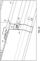
- the transition barrier 10 has a transition wall 40 with an outer profile 41 resembling the profile 21 of the permanent concrete median barrier 20 being the New Jersey Tall Wall keyed-in barrier.
- the outer profile 41 consists of a lower sloped wall 42 transitioning to a higher sloped wall 43.
- the transition wall 40 is made of steel. It may be made of a number of steel plates suitably joined together at the ends thereof or it may be a single steel plate. If joined together at the ends thereof, the joining technique should be one in which the joined plates will behave as a single steel plate.
- the transition wall is further rigidified by a number of spaced apart horizontal braces 50 ( FIG. 4A ) on the inner profile 44 thereof.
- each of said horizontal braces is tapered 51 downwards to the first end 60 to reduce the transition angle between the transition wall 40 and the permanent concrete median barrier 20.
- the transition angle is 3.1 degrees.
- Each of said horizontal braces 50 is a HSS (hollow structural section) with a hollow rectangular tubular cross section (although other suitable cross sections may be used) made of structural steel grade ASTM A500C.
- the top three of said horizontal braces are made of HSS 4x2x0.25 inches No. 1 and are positioned on the inner profile 44 of the higher sloped wall 43.
- the fourth of said horizontal braces is made of HSS 4x2x0.25 inches No. 2 and is position on the inner profile 44 of the lower sloped wall 42.
- Each of said horizontal braces 50 is welded onto the inner profile 44 of the transition wall 40.
- the transition wall 40 includes a number of backing plates 45 ( FIG. 4C ) between each of the spaced apart horizontal braces 50.
- Each of said backing plates is welded onto the inner profile 44 of the transition wall.
- the backing plates 45 serve to obtain optimal (preferably 100%) penetration welds to structurally simulate a single steel plate for the transition wall 40 .
- the inner profile 44 of the transition wall 40 includes a number of spaced apart vertical braces 70.
- each of said vertical braces 70 is made of HSS 6x6x0.313 inches.
- Each of said spaced apart vertical braces 70 is of a hollow rectangular tubular cross section (although other cross sections may be used).
- Each of said spaced apart vertical braces 70 is welded onto each of the horizontal braces 50.
- the first vertical brace 71 ( FIG. 5 , FIG. 6 , FIG. 7B , FIG. 8A ) proximate the first end 60 serves as a non-adjustable spacer to sit against the surface of the permanent concrete median barrier 20.
- the second vertical brace 72 ( FIG. 5 , FIG. 6 , FIG.
- first vertical brace 71 also serves as a non-adjustable spacer to sit against the surface of the permanent concrete median barrier 20.
- Vertical brace 72 extends beyond vertical brace 71 to compensate for the greater distance between the transition wall and the vertical brace 72.
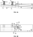
- the third 73 and fourth 74 vertical braces ( FIG. 3A , FIG. 5 , FIG. 6 , FIG. 7A , FIG.
- each brace plate 75 (shown in Figures 3A and 3B ) connected to each of the third 73 and fourth 74 vertical braces to a brace plate jack screw 76 by a ball joint 77 allowing each brace plate 75 to move along the length of the brace plate jack screw 76 and the ball joint 77 allowing each brace plate 75 to be adjusted on the plane thereof.
- Each brace plate 75 is a flat square configuration made of HSS. In this embodiment, the size of each brace plate 75 is 300mm by 300mm by 19mm thick. However, the brace plate may be of any size and shape that allows for transference of load during a collision or impact on the temporary transition barrier 10 from the transition wall 40 to the permanent concrete median barrier 20.
- the first end 60 of the transition wall 40 is attached to the surface of the permanent concrete median barrier 20 by a number of socket button head cap screws 61 and hardened flat washers with each screw having a hardened flat washer thereon. Each screw is then fastened in place in a complementary internal threaded insert 63 in the permanent concrete median barrier 30 ( FIG. 6 ).
- the angle made between the fastened transition wall 40 and the permanent concrete median barrier 30 is about 3.1 degrees. However, the angle may differ depending on the specific need.
- the second end 80 of the transition wall 40 is attached to the end 31 of the temporary median barrier 30 via steel shroud 90 enveloping the end 31 of the temporary median barrier 30 (See FIGS. 3A-3D ).
- the steel shroud 90 facilitates the shape of the transition wall 40 is maintained and that separation of the transition wall 40 from the horizontal braces 50 and vertical braces 70 is minimized.
- the steel shroud 90 is connected to the inner profile of the transition wall via a steel shroud vertical brace 100.
- the steel shroud vertical brace 100 is similar in shape as the vertical braces 70.
- the steel shroud is connected to the steel shroud vertical brace 100 by a threaded cross bolt system 91.
- the steel shroud is connected to the steel shroud vertical brace by a pair of threaded cross bolts.
- One end 92 of each threaded cross bolt is connected to the transition wall 40 with a threaded cross bolt nut 93.
- the second end 94 of each threaded cross bolt is connected to end 31 of the temporary median barrier 30 utilizing an x-type connection of the temporary median barrier 30 with a threaded cross bolt nut 93.
- a cup washer 95 is inserted into a complementary cross bolt void 96 found on the temporary median barrier 30 providing a bearing surface on the wall 40 further minimizing the temporary transition barrier 10 from separating from the temporary median barrier 30.
- the cup washer 95 has a low profile to minimize snagging of the sheet metal of a vehicle during impact.
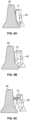
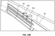
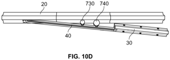
- FIG. 9A and 9B there is depicted a sign support system in use with the transition barrier wherein the sign support system is positioned and secured between parallel spaced apart temporary barriers 30. Barriers 30 are connected to permanent barriers 20 via transition wall 40.
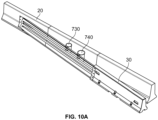
- spacers 730 and 740 are tubes made of round steel section (with or without internal stiffeners) grade ASTM A500C or similar HSS or pipe grades. Each spacer is secured on a horizontal brace of the transition wall 40 via a nut and bolt system (or equivalent). Depending on the spacing between the transition wall 40 and the median barrier 20, each spacer 730 and 740 is positioned along the length of the horizontal brace to provide a snug fit between the transition wall 40 and the median barrier 20 while absorbing and transferring any load from the transition wall 40 to the median barrier 20 during impact or collision.
- spacers 830 and 840 are similar to spacer 72 of Figure 7B , but the spacers 830 and 840 are adjustable along the horizontal brace by a spaced apart apertures 850 found along two horizontal braces.
- the spaced apart apertures 850 are situated along the portion of the horizontal braces between the vertical braces 70.
- the spacers 830 and 840 are each secured to the desired location by a threaded bolt and nut at the desired apertures 850.
- Example 1 Evaluation of the temporary transition barrier having a length of 10891.4 mm transitioning from a permanent 1049 mm Tall Wall New Jersey profile concrete median barrier to a temporary pinned-down, precast F-shape concrete barrier with a cross-bolt connection through MASH test 3-20
- the evaluation criteria for test MASH 3-20 includes assessing structural adequacy and occupant risk during impact by a test vehicle.
- Structural adequacy evaluation criteria includes the test article should contain and redirect the vehicle or bring the vehicle to a controlled stop; the vehicle should not penetrate, underride, or override the installation although controlled lateral deflection of the test article is acceptable (as per TABLE 5-1.
- Occupant risk evaluation criteria includes detached elements, fragments, or other debris from the test article should not penetrate or show potential for penetrating the occupant compartment, or present undue hazard to other traffic, pedestrians, or personnel in a work zone.
- Deformations of, or intrusions into, the occupant compartment should not exceed limits set forth in Section 5.3 as follows: roof ⁇ 4.0 in. (102 mm), windshield-no tear of plastic liner and maximum deformation of 3 in. (76 mm), window-no shattering of a side window resulting from direct contact with a structural member of the test article (this requires the side windows to be in the up position for testing)-in cases where the windows are laminated, the guidelines for windshields will apply, wheel/foot well and toe pan areas ⁇ 9 in. (229 mm), side front panel (forward of A-pillar) ⁇ 12 in. (305 mm), front side door area (above seat) ⁇ 9 in. (229 mm), front side door area (below seat) ⁇ 12 in.
- the temporary pinned-down precast F-shape barrier branched off from the permanent 1049 mm Tall Wall New Jersey profile concrete median barrier until it became parallel to the permanent 1049 mm Tall Wall New Jersey profile concrete median barrier.
- a second row of the precast pinned barrier branched off on the opposite side of the permanent 1049 mm Tall Wall New Jersey profile concrete median barrier as shown in Figure 8 .
- MASH test 3-20 involved impacting the temporary transition barrier at the critical impact point (CIP) with a small passenger vehicle (1100 kg test inertia mass) at a target impact speed and angle of 100 km/h and 25 degrees respectively, to the transition barrier. Actual impact speed and angle were within MASH specified tolerances. After the impact, the vehicle was successfully contained and redirected. The maximum occupant impact velocity (OIV) and the ridedown acceleration were within MASH specified tolerances.
- the temporary transition barrier complied with MASH 3-20.
- Example 2 Evaluation of the temporary transition barrier having a length of 10891.4 mm transitioning from a permanent 1049 mm Tall Wall New Jersey profile concrete median barrier to a temporary pinned-down, precast F-shape concrete barrier with a cross-bolt connection through MASH test 3-21
- MASH test 3-21 involves impacting the temporary transition barrier at the critical impact point (CIP) with a quad-cab pickup truck (2270 kg test inertia mass) at a target impact speed and angle of 100 km/h and 25 degrees respectively, to the transition barrier. Actual impact speed and angle were within MASH specified tolerances. After the impact, the vehicle was successfully contained and redirected. The maximum occupant impact velocity (OIV) and the ridedown acceleration were within MASH specified tolerances. The temporary transition barrier complied with MASH 3-21.
- CIP critical impact point
- OIV maximum occupant impact velocity
- ridedown acceleration were within MASH specified tolerances.
Landscapes
- Engineering & Computer Science (AREA)
- Architecture (AREA)
- Civil Engineering (AREA)
- Structural Engineering (AREA)
- Refuge Islands, Traffic Blockers, Or Guard Fence (AREA)
- Working Measures On Existing Buildindgs (AREA)
Claims (26)
- Übergangsleitplanke (10) zum Übergang von einer permanenten Mittelleitplanke (20) zu einer temporären Mittelleitplanke (30), die Übergangsleitplanke (10) umfassend:a) ein erstes Ende; wobei das erste Ende durch einen Permanentmittelleitplanken-Verbinder mit der permanenten Mittelleitplanke (20) verbindbar ist;b) ein zweites Ende; wobei das zweite Ende durch einen Temporärmittelleitplanken-Verbinder mit der temporären Mittelleitplanke (30) verbindbar ist;c) einen Übergangsabschnitt, der eine Übergangswand (40) einer vorbestimmten Länge zwischen dem ersten Ende und dem zweiten Ende definiert; wobei die Übergangswand (40) eine Oberseite, eine Unterseite, eine Vorderseite und eine Rückseite aufweist;d) mindestens eine Leitplankenstrebe in der Nähe der Übergangswand (40) zum Stützen der Übergangswand (40); unde) mindestens einen Abstandhalter in der Nähe der Rückseite der Übergangswand (40) für einen Kontakt mit einer Oberfläche der permanenten Mittelleitplanke (20), dadurch gekennzeichnet, dass der mindestens eine Abstandhalter eine Vielzahl von Abstandhaltern umfasst, wobei die Vielzahl von Abstandhaltern eine Kombination aus in der Länge festgelegten Abstandhaltern und in der Länge einstellbaren Abstandhaltern ist.
- Übergangsleitplanke (10) nach Anspruch 1, wobei die permanente Mittelleitplanke (20) eine permanente Betonmittelleitplanke (20) ist und die temporäre Mittelleitplanke (30) eine temporäre Betonmittelleitplanke (30) ist.
- Übergangsleitplanke (10) nach Anspruch 1 oder 2, das erste Ende ferner umfassend einen Permanentmittelleitplanken-Verbinder zum Verbinden des ersten Endes mit der permanenten Mittelleitplanke (20); und das zweite Ende ferner umfassend einen Temporärmittelleitplanken-Verbinder zum Verbinden des zweiten Endes mit der temporären Mittelleitplanke (30).
- Übergangsleitplanke (10) nach einem der Ansprüche 1-3, wobei die Übergangswand (40) ferner eine Form eines Profils der permanenten Mittelleitplanke (20) umfasst.
- Übergangsleitplanke (10) nach einem der Ansprüche 1-4, wobei die Leitplankenstrebe in der Nähe der Rückseite der Übergangswand (40) ist.
- Übergangsleitplanke (10) nach Anspruch 1 oder 2, wobei mindestens einer der längenverstellbaren Abstandhalter ferner eine Kontaktplatte für einen Kontakt mit der Oberfläche der permanenten Mittelleitplanke (20) umfasst.
- Übergangsleitplanke (10) nach einem der Ansprüche 1-6, wobei der Permanentmittelleitplanken-Verbinder einen Annäherungswinkel von etwa 0 bis etwa 10 Grad von der Mittellinie der permanenten Mittelleitplanke (20) zulässt.
- Übergangsleitplanke (10) nach Anspruch 7, wobei der Annäherungswinkel kleiner als etwa 6 Grad ist.
- Übergangsleitplanke (10) nach Anspruch 7, wobei der Annäherungswinkel kleiner als etwa 5 Grad ist.
- Übergangsleitplanke (10) nach Anspruch 7, wobei der Annäherungswinkel kleiner als oder gleich wie etwa 4 Grad ist.
- Übergangsleitplanke (10) nach einem der Ansprüche 1-10, wobei der Permanentmittelleitplanken-Verbinder mindestens ein Anker ist.
- Übergangsleitplanke (10) nach Anspruch 11, wobei der mindestens eine Anker ein Betonanker ist.
- Übergangsleitplanke (10) nach Anspruch 1-10, wobei der Permanentmittelleitplanken-Verbinder eine Vielzahl von Betonankern ist, wobei jeder der Betonanker einen flachen, nicht einschnürenden Kopf aufweist, um ein Verhaken von Blech eines Fahrzeugs während eines Aufpralls auf die Übergangsleitplanke (10) zu mildern.
- Übergangsleitplanke (10) nach einem der Ansprüche 1-10 und 13, wobei der Temporärmittelleitplanken-Verbinder mindestens ein Betonanker ist.
- Übergangsleitplanke (10) nach einem der Ansprüche 1-10 und 13, wobei der Temporärmittelleitplanken-Verbinder eine Vielzahl von Betonankern ist.
- Übergangsleitplanke (10) nach Anspruch 5, wobei die mindestens eine Leitplankenstrebe über eine vorbestimmte horizontale Länge der Übergangswand (40) verläuft.
- Übergangsleitplanke (10) nach Anspruch 16, wobei die mindestens eine Leitplankenstrebe über eine wesentlich horizontale Länge der Übergangswand (40) verläuft, wobei ein erstes Ende der mindestens einen Leitplankenstrebe in der Nähe des ersten Endes der Übergangsleitplanke (10) und ein zweites Ende der mindestens einen Leitplankenstrebe in der Nähe des zweiten Endes der Übergangsleitplanke (10) liegt.
- Übergangsleitplanke (10) nach Anspruch 17, wobei die mindestens eine Leitplankenstrebe eine Vielzahl von Leitplankenstreben ist, die über eine vorbestimmte horizontale Länge der Übergangswand (40) verlaufen.
- Übergangsleitplanke (10) nach Anspruch 18, wobei die Vielzahl von Leitplankenstreben voneinander beabstandet sind und jeweils einstückig mit der Rückseite der Übergangswand (40) ausgebildet sind; bevorzugter ist, dass die Vielzahl der beabstandeten Leitplankenstreben jeweils einstückig mit der Rückseite der Übergangswand (40) ausgebildet sind.
- Übergangsleitplanke (10) nach einem der Ansprüche 1 bis 10, 16 bis 19, wobei die Leitplankenstrebe eine Position an der Übergangswand (40) in einer Höhe aufweist, die im Wesentlichen der Höhe eines Standardstoßfängers eines Fahrzeugs entspricht.
- Übergangsleitplanke (10) nach Anspruch 1 oder 2, wobei sich der mindestens eine in der Länge verstellbare Abstandshalter in der Nähe des zweiten Endes der Übergangsleitplanke (10) befindet.
- Übergangsleitplanke (10) nach Anspruch 1, 2 oder 21, wobei mindestens einer der in der Länge verstellbaren Abstandshalter verstellbar ist, um eine Kompressionspassung zwischen der Übergangsleitplanke (10) und der permanenten Mittelleitplanke (20) zu erreichen, wodurch Durchbiegung während des Aufpralls minimiert wird.
- Übergangsleitplanke (10) nach einem der Ansprüche 1 bis 22, wobei die Übergangsleitplanke (10) temporär ist.
- Verfahren zum Bilden einer Übergangsleitplanke (10) zwischen zwei voneinander beabstandeten Mittelleitplanken, wobei das Verfahren Folgendes umfasst:i) Verbinden eines ersten Endes der Übergangsleitplanke (10) nach einem der Ansprüche 1 bis 23 mit einem Ende einer ersten Mittelleitplanke; undii)Verbinden eines zweiten Endes der Übergangsleitplanke (10) nach einem der Ansprüche 1 bis 23 mit einem Ende einer zweiten Mittelleitplanke, wobei eine Übergangsleitplanke (10) zwischen den zwei beabstandeten Mittelleitplanken gebildet wird.
- Verfahren nach Anspruch 24, wobei die erste Mittelleitplanke eine permanente Betonmittelleitplanke (20) ist und die zweite Mittelleitplanke eine temporäre Betonmittelleitplanke (30) ist.
- Übergangsleitplanke (10) nach einem der Ansprüche 1 bis 22, wobei die Übergangsleitplanke (10) MASH-konform ist.
Applications Claiming Priority (2)
| Application Number | Priority Date | Filing Date | Title |
|---|---|---|---|
| CA2936510A CA2936510C (en) | 2016-07-19 | 2016-07-19 | A transition barrier for connecting a permanent barrier to a temporary barrier |
| PCT/CA2017/050859 WO2018014121A1 (en) | 2016-07-19 | 2017-07-17 | A transition barrier for connecting a permanent barrier to a temporary barrier |
Publications (4)
| Publication Number | Publication Date |
|---|---|
| EP3497288A1 EP3497288A1 (de) | 2019-06-19 |
| EP3497288A4 EP3497288A4 (de) | 2021-05-26 |
| EP3497288B1 true EP3497288B1 (de) | 2024-12-04 |
| EP3497288C0 EP3497288C0 (de) | 2024-12-04 |
Family
ID=60989338
Family Applications (1)
| Application Number | Title | Priority Date | Filing Date |
|---|---|---|---|
| EP17830144.6A Active EP3497288B1 (de) | 2016-07-19 | 2017-07-17 | Übergangsbarriere zum verbinden einer permanenten barriere mit einer temporären barriere |
Country Status (6)
| Country | Link |
|---|---|
| US (1) | US11585057B2 (de) |
| EP (1) | EP3497288B1 (de) |
| AU (1) | AU2017298579B2 (de) |
| CA (1) | CA2936510C (de) |
| MX (1) | MX2019000783A (de) |
| WO (1) | WO2018014121A1 (de) |
Families Citing this family (4)
| Publication number | Priority date | Publication date | Assignee | Title |
|---|---|---|---|---|
| US11629465B2 (en) * | 2017-05-16 | 2023-04-18 | Systemes Versilis Inc. | Gate for controlling oncoming traffic on a roadway |
| USD913775S1 (en) * | 2018-07-26 | 2021-03-23 | Industrial Galvanizers Corporation Pty Ltd | Spacer block |
| CN112081009A (zh) * | 2020-09-28 | 2020-12-15 | 上海市机械施工集团有限公司 | 桥梁防撞墙及其施工方法 |
| CN115262449A (zh) * | 2022-07-10 | 2022-11-01 | 张传永 | 一种具有缓冲吸能机构的高速公路施工用临时防护装置 |
Family Cites Families (27)
| Publication number | Priority date | Publication date | Assignee | Title |
|---|---|---|---|---|
| US4406563A (en) | 1981-03-30 | 1983-09-27 | Urlberger Hermann Hans | Protective barrier provided with at least one longitudinal side bar |
| US4815565A (en) * | 1986-12-15 | 1989-03-28 | Sicking Dean L | Low maintenance crash cushion end treatment |
| DE4202986C3 (de) | 1992-02-03 | 2002-03-07 | Wilhelm Junker | Fußschwelle für eine Leiteinrichtung |
| US5314261A (en) * | 1993-02-11 | 1994-05-24 | Energy Absorption Systems, Inc. | Vehicle crash cushion |
| US6024341A (en) * | 1997-05-05 | 2000-02-15 | Traffix Devices, Inc. | Crash attenuator of compressible sections |
| US5860762A (en) * | 1997-10-25 | 1999-01-19 | Nelson; Charles B. | Energy absorbing barrier system |
| US6783116B2 (en) * | 1999-01-06 | 2004-08-31 | Trn Business Trust | Guardrail end terminal assembly having at least one angle strut |
| US6533250B2 (en) * | 1999-10-15 | 2003-03-18 | W. Eugene Arthur | Energy dissipating system for a concrete roadway barrier |
| ITMI20010521A1 (it) | 2001-03-12 | 2002-09-12 | Snoline Spa | Transizione tra barriere di sicurezza per la chiusura facilmente amovibile |
| US20030081997A1 (en) * | 2001-10-25 | 2003-05-01 | Rick Kramer | Vehicle crash wall |
| US6926461B1 (en) * | 2002-04-08 | 2005-08-09 | Board Of Regents Of University Of Nebraska | High-impact, energy-absorbing vehicle barrier system |
| US7059590B2 (en) * | 2002-06-19 | 2006-06-13 | Trn Business Trust | Impact assembly for an energy absorbing device |
| AU2002950330A0 (en) | 2002-07-24 | 2002-09-12 | Waytogo Aussindo Pty Ltd | Transportable safety crash barrier |
| US7410320B2 (en) * | 2004-08-31 | 2008-08-12 | Board Of Regents Of University Of Nebraska | High-impact, energy-absorbing vehicle barrier system |
| DE502005000448D1 (de) | 2004-10-06 | 2007-04-19 | Tss Tech Sicherheits Systeme G | Übergangskonstruktion |
| KR100538994B1 (ko) * | 2005-09-21 | 2005-12-27 | 주식회사 선진엔지니어링 종합건축사 사무소 | 다단의 충격흡수형 도로용 가드레일 |
| US8500103B2 (en) | 2006-03-01 | 2013-08-06 | The Texas A&M University System | Yielding post guardrail safety system incorporating thrie beam guardrail elements |
| DE202006015433U1 (de) | 2006-09-01 | 2007-02-08 | Sps Schutzplanken Gmbh | Übergangskonstruktion |
| DE202006015432U1 (de) | 2006-09-21 | 2007-02-01 | Sps Schutzplanken Gmbh | Kontinuierliche Übergangskonstruktion |
| DE202006017431U1 (de) | 2006-11-14 | 2007-02-22 | Sps Schutzplanken Gmbh | Übergangskonstruktion mit Betonelementen |
| DE102007042392A1 (de) | 2007-09-04 | 2009-03-05 | Innotraffic.Net Gmbh | Leiteinrichtung an Verkehrswegen mit zwei Rückhaltesystemen unterschiedlicher Steifigkeit und einer Übergangskonstruktion zwischen diesen |
| US8043024B2 (en) * | 2008-02-12 | 2011-10-25 | Michael John Lamore | Pivot swivel cable barrier |
| DE102008056807A1 (de) | 2008-11-11 | 2010-05-27 | Linetech Gmbh & Co. Kg | Fahrbahnbegrenzung mit Wechsel zwischen zwei Rückhaltesystemen unterschiedlicher Nachgiebigkeit |
| DE202009001131U1 (de) | 2009-01-29 | 2009-04-02 | Tss Technische Sicherheits-Systeme Gmbh | Übergangskonstruktion zwischen Betonleitwänden |
| DE202009016995U1 (de) | 2009-12-16 | 2010-04-08 | Tss Technische Sicherheits-Systeme Gmbh | Verbindungselement sowie Verbindungssystem zum Verbinden von Betonleitwänden |
| EP2339071B1 (de) | 2009-12-22 | 2015-04-15 | Strabag Ag | Überbrückungselement sowie Fahrbahnbegrenzungselement |
| US9404231B2 (en) | 2014-08-26 | 2016-08-02 | The Texas A&M University System | Module for use in a crash barrier and crash barrier |
-
2016
- 2016-07-19 CA CA2936510A patent/CA2936510C/en active Active
-
2017
- 2017-07-17 US US16/318,751 patent/US11585057B2/en active Active
- 2017-07-17 MX MX2019000783A patent/MX2019000783A/es unknown
- 2017-07-17 EP EP17830144.6A patent/EP3497288B1/de active Active
- 2017-07-17 AU AU2017298579A patent/AU2017298579B2/en active Active
- 2017-07-17 WO PCT/CA2017/050859 patent/WO2018014121A1/en not_active Ceased
Also Published As
| Publication number | Publication date |
|---|---|
| US11585057B2 (en) | 2023-02-21 |
| WO2018014121A1 (en) | 2018-01-25 |
| CA2936510C (en) | 2022-08-30 |
| AU2017298579A1 (en) | 2019-02-28 |
| EP3497288C0 (de) | 2024-12-04 |
| AU2017298579B2 (en) | 2023-02-02 |
| US20190242080A1 (en) | 2019-08-08 |
| EP3497288A4 (de) | 2021-05-26 |
| CA2936510A1 (en) | 2018-01-19 |
| MX2019000783A (es) | 2020-01-09 |
| EP3497288A1 (de) | 2019-06-19 |
Similar Documents
| Publication | Publication Date | Title |
|---|---|---|
| US8157471B2 (en) | Combined guardrail and cable safety systems | |
| US6422783B1 (en) | Breakaway post slipbase | |
| US4678166A (en) | Eccentric loader guardrail terminal | |
| US7988133B2 (en) | Combined guardrail and cable safety systems | |
| EP3497288B1 (de) | Übergangsbarriere zum verbinden einer permanenten barriere mit einer temporären barriere | |
| US20140110651A1 (en) | Guardrail | |
| US7913981B2 (en) | Cable release lever | |
| EP1612333A1 (de) | Pfosten | |
| CA3184560A1 (en) | Barrier transition framework | |
| US11326314B2 (en) | Deflector bracket and cable anchor for guardrail terminal | |
| US7171774B1 (en) | Sign support | |
| NO750906L (de) | ||
| EP4560076A1 (de) | Barrierenübergangsrahmen | |
| Mauer et al. | Development and testing of steel U-channel slip safe sign support | |
| AU2023233067A1 (en) | Barrier transition framework | |
| AU2017298574B2 (en) | Apparatus and method for attaching signs to foundation members such as road barriers | |
| Jehu | Paper 1: Crash Barrier Developments | |
| MX2007007668A (es) | Terminal deslizadora de amortiguamiento de impactos. |
Legal Events
| Date | Code | Title | Description |
|---|---|---|---|
| STAA | Information on the status of an ep patent application or granted ep patent |
Free format text: STATUS: THE INTERNATIONAL PUBLICATION HAS BEEN MADE |
|
| PUAI | Public reference made under article 153(3) epc to a published international application that has entered the european phase |
Free format text: ORIGINAL CODE: 0009012 |
|
| STAA | Information on the status of an ep patent application or granted ep patent |
Free format text: STATUS: REQUEST FOR EXAMINATION WAS MADE |
|
| 17P | Request for examination filed |
Effective date: 20190215 |
|
| AK | Designated contracting states |
Kind code of ref document: A1 Designated state(s): AL AT BE BG CH CY CZ DE DK EE ES FI FR GB GR HR HU IE IS IT LI LT LU LV MC MK MT NL NO PL PT RO RS SE SI SK SM TR |
|
| AX | Request for extension of the european patent |
Extension state: BA ME |
|
| DAV | Request for validation of the european patent (deleted) | ||
| DAX | Request for extension of the european patent (deleted) | ||
| REG | Reference to a national code |
Ref country code: HK Ref legal event code: DE Ref document number: 40010274 Country of ref document: HK |
|
| A4 | Supplementary search report drawn up and despatched |
Effective date: 20210423 |
|
| RIC1 | Information provided on ipc code assigned before grant |
Ipc: E01F 15/02 20060101AFI20210419BHEP Ipc: E01F 15/08 20060101ALI20210419BHEP Ipc: E01F 15/14 20060101ALI20210419BHEP |
|
| STAA | Information on the status of an ep patent application or granted ep patent |
Free format text: STATUS: EXAMINATION IS IN PROGRESS |
|
| 17Q | First examination report despatched |
Effective date: 20230317 |
|
| GRAP | Despatch of communication of intention to grant a patent |
Free format text: ORIGINAL CODE: EPIDOSNIGR1 |
|
| STAA | Information on the status of an ep patent application or granted ep patent |
Free format text: STATUS: GRANT OF PATENT IS INTENDED |
|
| RAP1 | Party data changed (applicant data changed or rights of an application transferred) |
Owner name: THE TEXAS A&M UNIVERSITY SYSTEM Owner name: POWELL (RICHMOND HILL) CONTRACTING LIMITED |
|
| INTG | Intention to grant announced |
Effective date: 20240624 |
|
| GRAS | Grant fee paid |
Free format text: ORIGINAL CODE: EPIDOSNIGR3 |
|
| GRAA | (expected) grant |
Free format text: ORIGINAL CODE: 0009210 |
|
| STAA | Information on the status of an ep patent application or granted ep patent |
Free format text: STATUS: THE PATENT HAS BEEN GRANTED |
|
| AK | Designated contracting states |
Kind code of ref document: B1 Designated state(s): AL AT BE BG CH CY CZ DE DK EE ES FI FR GB GR HR HU IE IS IT LI LT LU LV MC MK MT NL NO PL PT RO RS SE SI SK SM TR |
|
| REG | Reference to a national code |
Ref country code: GB Ref legal event code: FG4D |
|
| REG | Reference to a national code |
Ref country code: CH Ref legal event code: EP |
|
| REG | Reference to a national code |
Ref country code: DE Ref legal event code: R096 Ref document number: 602017086584 Country of ref document: DE |
|
| REG | Reference to a national code |
Ref country code: IE Ref legal event code: FG4D |
|
| U01 | Request for unitary effect filed |
Effective date: 20250107 |
|
| U07 | Unitary effect registered |
Designated state(s): AT BE BG DE DK EE FI FR IT LT LU LV MT NL PT RO SE SI Effective date: 20250113 |
|
| PG25 | Lapsed in a contracting state [announced via postgrant information from national office to epo] |
Ref country code: HR Free format text: LAPSE BECAUSE OF FAILURE TO SUBMIT A TRANSLATION OF THE DESCRIPTION OR TO PAY THE FEE WITHIN THE PRESCRIBED TIME-LIMIT Effective date: 20241204 |
|
| PG25 | Lapsed in a contracting state [announced via postgrant information from national office to epo] |
Ref country code: ES Free format text: LAPSE BECAUSE OF FAILURE TO SUBMIT A TRANSLATION OF THE DESCRIPTION OR TO PAY THE FEE WITHIN THE PRESCRIBED TIME-LIMIT Effective date: 20241204 |
|
| PG25 | Lapsed in a contracting state [announced via postgrant information from national office to epo] |
Ref country code: NO Free format text: LAPSE BECAUSE OF FAILURE TO SUBMIT A TRANSLATION OF THE DESCRIPTION OR TO PAY THE FEE WITHIN THE PRESCRIBED TIME-LIMIT Effective date: 20250304 |
|
| PG25 | Lapsed in a contracting state [announced via postgrant information from national office to epo] |
Ref country code: GR Free format text: LAPSE BECAUSE OF FAILURE TO SUBMIT A TRANSLATION OF THE DESCRIPTION OR TO PAY THE FEE WITHIN THE PRESCRIBED TIME-LIMIT Effective date: 20250305 |
|
| PG25 | Lapsed in a contracting state [announced via postgrant information from national office to epo] |
Ref country code: RS Free format text: LAPSE BECAUSE OF FAILURE TO SUBMIT A TRANSLATION OF THE DESCRIPTION OR TO PAY THE FEE WITHIN THE PRESCRIBED TIME-LIMIT Effective date: 20250304 |
|
| PG25 | Lapsed in a contracting state [announced via postgrant information from national office to epo] |
Ref country code: SM Free format text: LAPSE BECAUSE OF FAILURE TO SUBMIT A TRANSLATION OF THE DESCRIPTION OR TO PAY THE FEE WITHIN THE PRESCRIBED TIME-LIMIT Effective date: 20241204 |
|
| PG25 | Lapsed in a contracting state [announced via postgrant information from national office to epo] |
Ref country code: PL Free format text: LAPSE BECAUSE OF FAILURE TO SUBMIT A TRANSLATION OF THE DESCRIPTION OR TO PAY THE FEE WITHIN THE PRESCRIBED TIME-LIMIT Effective date: 20241204 |
|
| PG25 | Lapsed in a contracting state [announced via postgrant information from national office to epo] |
Ref country code: IS Free format text: LAPSE BECAUSE OF FAILURE TO SUBMIT A TRANSLATION OF THE DESCRIPTION OR TO PAY THE FEE WITHIN THE PRESCRIBED TIME-LIMIT Effective date: 20250404 |
|
| U1N | Appointed representative for the unitary patent procedure changed after the registration of the unitary effect |
Representative=s name: BIRD & BIRD SOCIETA TRA AVVOCATI S.R.L.; IT |
|
| PG25 | Lapsed in a contracting state [announced via postgrant information from national office to epo] |
Ref country code: SK Free format text: LAPSE BECAUSE OF FAILURE TO SUBMIT A TRANSLATION OF THE DESCRIPTION OR TO PAY THE FEE WITHIN THE PRESCRIBED TIME-LIMIT Effective date: 20241204 |
|
| PG25 | Lapsed in a contracting state [announced via postgrant information from national office to epo] |
Ref country code: CZ Free format text: LAPSE BECAUSE OF FAILURE TO SUBMIT A TRANSLATION OF THE DESCRIPTION OR TO PAY THE FEE WITHIN THE PRESCRIBED TIME-LIMIT Effective date: 20241204 |
|
| U20 | Renewal fee for the european patent with unitary effect paid |
Year of fee payment: 9 Effective date: 20250714 |
|
| PLBE | No opposition filed within time limit |
Free format text: ORIGINAL CODE: 0009261 |
|
| STAA | Information on the status of an ep patent application or granted ep patent |
Free format text: STATUS: NO OPPOSITION FILED WITHIN TIME LIMIT |
|
| 26N | No opposition filed |
Effective date: 20250905 |