EP3496972B1 - In eine tisch verwandelbare konsole für ein kraftfahreug mit optimierter sicherheit - Google Patents
In eine tisch verwandelbare konsole für ein kraftfahreug mit optimierter sicherheit Download PDFInfo
- Publication number
- EP3496972B1 EP3496972B1 EP17758223.6A EP17758223A EP3496972B1 EP 3496972 B1 EP3496972 B1 EP 3496972B1 EP 17758223 A EP17758223 A EP 17758223A EP 3496972 B1 EP3496972 B1 EP 3496972B1
- Authority
- EP
- European Patent Office
- Prior art keywords
- box
- console
- internal structure
- tray
- motor vehicle
- Prior art date
- Legal status (The legal status is an assumption and is not a legal conclusion. Google has not performed a legal analysis and makes no representation as to the accuracy of the status listed.)
- Active
Links
Images


Classifications
-
- B—PERFORMING OPERATIONS; TRANSPORTING
- B60—VEHICLES IN GENERAL
- B60N—SEATS SPECIALLY ADAPTED FOR VEHICLES; VEHICLE PASSENGER ACCOMMODATION NOT OTHERWISE PROVIDED FOR
- B60N3/00—Arrangements or adaptations of other passenger fittings, not otherwise provided for
- B60N3/001—Arrangements or adaptations of other passenger fittings, not otherwise provided for of tables or trays
- B60N3/002—Arrangements or adaptations of other passenger fittings, not otherwise provided for of tables or trays of trays
-
- B—PERFORMING OPERATIONS; TRANSPORTING
- B60—VEHICLES IN GENERAL
- B60N—SEATS SPECIALLY ADAPTED FOR VEHICLES; VEHICLE PASSENGER ACCOMMODATION NOT OTHERWISE PROVIDED FOR
- B60N3/00—Arrangements or adaptations of other passenger fittings, not otherwise provided for
- B60N3/001—Arrangements or adaptations of other passenger fittings, not otherwise provided for of tables or trays
-
- B—PERFORMING OPERATIONS; TRANSPORTING
- B60—VEHICLES IN GENERAL
- B60R—VEHICLES, VEHICLE FITTINGS, OR VEHICLE PARTS, NOT OTHERWISE PROVIDED FOR
- B60R7/00—Stowing or holding appliances inside vehicle primarily intended for personal property smaller than suit-cases, e.g. travelling articles, or maps
- B60R7/04—Stowing or holding appliances inside vehicle primarily intended for personal property smaller than suit-cases, e.g. travelling articles, or maps in driver or passenger space, e.g. using racks
Definitions
- the present invention relates to the arrangement of the passenger compartment of motor vehicles of the minivan or utility type, which comprise several rows of side seats arranged symmetrically on either side of the median longitudinal axis of the vehicle.
- the invention relates in particular to a console convertible into a table intended to be slidably mounted on the floor of such a vehicle along its median longitudinal axis.
- Modular passenger compartment type vehicles and van type utility vehicles dedicated to passenger transport are increasingly used in a “leisure” context, in particular during vacation periods.
- the latter is generally retractable.
- a console slidably mounted on the floor along the median longitudinal axis of the vehicle and comprising a box defining at least one vertical lateral housing accessible by an entry slot, as well as at least one plate movably mounted on said box between a row configuration in which said plate is housed in a corresponding said housing and an extended configuration in which said plate extends horizontally so as to form a table.
- the console box which constitutes the foot of the table must therefore be high enough so that the use of the table is ergonomic for the user, which results in a significant mass of the console.
- This type of console has the advantage of being particularly compact in its retracted configuration while offering in its service configuration excellent ergonomics of use of the table thanks to its raised position.
- the tray (s) may be ejected sliding towards the rear of their respective housings, which may cause injury. for passengers located nearby.
- the present invention therefore aims to ensure that the tray or trays are held inside their respective housings when the console is in its retracted configuration.
- the plate is prevented from sliding longitudinally when the console occupies its retracted configuration and therefore cannot be ejected from its housing even in the event of a violent impact.
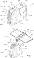
- Console 1 shown on figures 1 to 4 is intended to be slidably mounted on the floor of a motor vehicle of the MPV or utility type along the median longitudinal axis of this vehicle between the two seats of each of the different rows of seats.
- the console 1 consists of a storage support box 100 as well as a table box 200 articulated on this storage support box.
- the storage support box 100 has an internal structure 110 covered with an envelope 150.
- the internal structure 110 better visible on the figure 3 consists of two symmetrical shells 110A, 110B obtained separately by molding from a thermoplastic polymer and then assembled to one another by a plurality of fixing screws.
- the polymer used is preferably a polyamide advantageously filled with glass fibers such as PA6 GF50.
- This internal structure 110 comprises in the lower part a male longitudinal guide rail 113 intended to be mounted so as to slide inside and along a fixed female rail installed in the floor along the median longitudinal axis of the vehicle.
- the internal structure 110 also comprises a hollow support leg 120 extending substantially vertically above the rear part of the rail 113 and the upper end of which carries an axis of transverse articulation A and around which the table box 200 is pivotally articulated.
- the internal structure 110 further comprises, at the front of the leg 120 and above the rail 113, a container 130 open on the top and defining a storage cavity.
- the envelope 150 open to the rear is delimited by a front facade 151, an upper wall 152 and two side flanges 153.
- the upper wall 152 has a rectangular window 155 located directly above the storage bin 130 and through which users have access to this bin 130.
- the envelope 150 further comprises a slatted cover curtain 156 slidably mounted along and below the front facade 151 and the top wall 152 between an open position in which it is concealed behind the front facade 151 and where the access window 155 is open ( figure 1 ), and a closed position in which it covers this access window 155 ( figure 2 ).
- the table box 200 has an L-shaped internal structure 210 whose side faces are covered by two side plates 221 having notched profiles in an arc of a circle complementary to those of the two side plates 153 of the casing 150 of the storage support box 100.
- This internal structure 210 comprises a first branch 213 articulated to pivot on the leg 120 of the internal structure 110, as well as a second branch 214 being perpendicular to it ( figure 3 ).
- the outer edges of the structure 210 are also covered with a covering 222, the portion of which covering the second branch 214 has cylindrical recesses 223 constituting cup holders suitable for receiving, for example, cans or bottles housed in the storage bin. 130 ( figure 2 ).
- the table box 200 further comprises an unlocking handle 224 mounted on the first branch 213 of the internal structure 210 and accessible from the outside of this box 200 thanks to a cutout made in the casing 222.
- This handle 224 connected to an internal mechanism (not detailed here and not forming the subject of the present invention), allows the user to pivot this table box 200 between a folded position in which it extends into the rear extension of the support storage box 100 ( figure 1 ), and a position raised at 90 ° in which it extends above the rear of the same storage support box 100 ( figure 2 ).
- the first and second branches 214 of the L-shaped internal structure 210 extend horizontally and vertically respectively; while the side flanges 221 and those complementary 153 of the storage support box 100 form, two by two, two continuous side flanges substantially rectangular ( figure 1 ).
- the first branch 213 of the internal L-shaped structure 210 vertically extends the support leg 120 to form with it a support upright, while the second branch 214 extends horizontally towards the rear and therefore the opposite of the storage bin 130.
- the table box 200 defines two vertical side housings 225 opposite transversely and each capable of receiving via a respective inlet slot 227 a corresponding rectangular plate 241 ( figure 2 ).
- Each plate 241 comprises a rectangular metal panel 242 (preferably aluminum to limit the mass) bordered by three outer edges front 243, upper 244 and lower 245.
- Each of the trays 241 is further movably mounted on the table box 200 by sliding guide means and pivoting between a stowed position in which it is received in the corresponding housing 225 extending generally in a vertical longitudinal plane ( figures 1 , 3 and 5 ), and a deployed position in which it extends almost entirely out of its housing 225 in a substantially horizontal plane and parallel to the second branch 214 of the internal L-shaped structure 210 to form a half table ( figure 2 ).
- the sliding and pivoting guide means comprise, for each plate 241, a cylindrical metal beam 250 integral with the internal structure 210 of the table box 200 and extending along the entry slot 227 of the corresponding housing 225, thus a guide plate 260 rotatably mounted in the central part of the beam 250 ( figure 3 ).
- the plate 260 is also mounted integrally to slide along a section 246 extending along the outer face of the panel 242 at its median plane ( figures 4 and 5 ).
- the sliding and pivoting guide means also comprise, for each plate 241, two complementary guide members 270 formed along the internal face of the corresponding lateral flange 221 and capable of being successively slidably traversed by the profile 246 of the plate 241. when stored in housing 225 ( figures 3 and 5 ).
- the console 1 is therefore able to switch from a retracted configuration in which the table box 200 occupies its folded position while the trays 241 are in the stored position ( figure 1 ), to a service configuration in which this table box 200 occupies its raised position while the trays 241 extend horizontally in the deployed position on either side of the box 200 so as to form a table ( figure 2 ).
- the user will first pivot the table box 200 into the raised position and then slide the trays 241 out vertically from their respective housings 225 before rotating them to the raised position. horizontal to bring them to the deployed position.
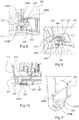
- the console 1 also comprises two retaining fingers 280 rooted at the top of the internal structure 110 of the box 100 near the transverse articulation axis A and transversely opposite to each other, each of them. them pointing downwards following an arcuate profile centered on this axis A ( figures 4 to 7 ).
- These two fingers 280 are advantageously molded as a single piece with a corresponding shell 110A, 110B of the internal structure 110.
- Each finger 280 is able to be introduced, during the pivotal folding of the table box 200 while the trays 241 occupy their stored position, into a respective slightly oblong orifice 247 formed on the upper outer edge 244 of a corresponding tray 241 to proximity to its upper front corner closest to the hinge axis A ( figure 4 ).
- the two fingers 280 advantageously have at their respective free end a profile tapering to a point.
- the console 1 further comprises two retaining members 290 rooted in the lower part of the internal structure 110 of the box 100 transversely opposite to each other and vertically to the fingers 280 ( figures 4 to 7 ).
- These two retaining members 290 are advantageously molded in one piece with a corresponding shell 110A, 110B of the internal structure 110.
- each of the members 290 comprises a foot 291 extending transversely from a lateral face respective external of the internal structure 110 and being extended by a leg 292 in the form of a marine anchor extending rearward in a substantially vertical plane and parallel to this external lateral face to a rounded free end 293 slightly curved on the external side.
- Each tab 292 comprises a rigid central branch 294 connected to the foot 291 as well as two elastically deformable fins 295 extending symmetrically on either side of this central branch 294 from this curved free end 293.
- the fins 295 are each constituted by an oblique proximal portion 295A extending at the front by a distal portion 295B extending parallel to the central branch 294.
- the tabs 290 are provided at their foot with at least one reinforcing rib 296 ( figure 9 ).
- Each tab 292 is able to cooperate with a rectangular cutout 248 of corresponding height made on the front outer edge 243 of the plate 241 near its lower front corner ( figures 8 to 11 ).
- each tab 292 is gradually introduced into a corresponding cutout 248.
- the oblique proximal portions 295A of the fins 295 form guide ramps respectively for a respective upper edge 248A or lower 248B of a cutout 248 ( figure 8 ), while the curved free end 293 constitutes such a guide ramp for its lateral edge 248C ( figure 10 ).
- the front ends of the plates 241 are thus prevented by the tabs 292 from moving vertically when the console 1 is subjected to vibrations while the vehicle is moving.
- each tab 292 and the corresponding external face of the internal structure 110 is predetermined so that, during the pivotal folding of the table box 200 while the trays 241 occupy their stored position, the portion of each plate 241 located at its cutout 248 is sandwiched between a tab 292 and a corresponding external side face of the internal structure 110 ( figure 10 ).
- each internal edge 248C of a cutout 248 rests against a tab 292 while the internal face of each plate 241 rests on an external lateral face of the internal structure 110.
- the front ends of the plates 241 are thus prevented by the tabs 292 from moving transversely when the console 1 is subjected to vibrations while the vehicle is moving.
- each plate 241 has a rib 249 through which contact is made between the latter and the external lateral face of the internal structure 110 during the folding of the table box 200.
- the console could for example have only one plate associated with a single housing and forming the table when it occupies its deployed position.
Landscapes
- Engineering & Computer Science (AREA)
- Mechanical Engineering (AREA)
- Transportation (AREA)
- Vehicle Step Arrangements And Article Storage (AREA)
- Packaging Of Machine Parts And Wound Products (AREA)
Claims (10)
- Konsole für ein Kraftfahrzeug, die dazu bestimmt ist, auf dem Boden des Fahrzeugs entlang seiner Längsmittelachse verschiebbar montiert zu werden, mit :- einen ersten Kasten (100) mit einer inneren Struktur (110);- einen zweiten Kasten (200), der schwenkbar an der inneren Struktur (110) um eine erste quer verlaufende Scharnierachse (A) montiert ist und mindestens ein vertikales seitliches Gehäuse (217, 218) definiert; undeinen zweiten Kasten (200), der Folgendes umfasst: einen ersten Kasten (100), der eine innere Struktur (110) umfasst; und einen zweiten Kasten (200), der einen zweiten Kasten (200) umfasst, der schwenkbar an der inneren Struktur (110) um eine zweite quer verlaufende Scharnierachse (A) montiert ist und mindestens ein vertikales seitliches Gehäuse (217, 218) definiert; dadurch gekennzeichnet, dass der zweite Kasten (200) an der inneren Struktur (110) montiert ist und schwenkbar an der inneren Struktur (110) um eine zweite quer verlaufende Scharnierachse (A) montiert ist.- mindestens eine Platte (221, 222), die beweglich auf dem genannten zweiten Kasten (200) montiert ist;wobei die Konsole in der Lage ist, :- aus einer eingezogenen Konfiguration, in der der zweite Kasten (200) eine gefaltete Position einnimmt, in der er sich in die hintere Verlängerung des ersten Kastens (100) erstreckt, während die mindestens eine Ablage (221, 222) eine Stauposition einnimmt, in der sie in einer entsprechenden vertikalen seitlichen Aufnahme (217, 218) aufgenommen ist;- zu einer Servicekonfiguration, in der der zweite Kasten (200) nach oben in eine angehobene Position geschwenkt worden ist, die sich über und zur Rückseite des ersten Kastens (100) erstreckt, während sich das mindestens eine Tablett (221, 222) horizontal erstreckt, um einen Tisch zu bilden;dadurch gekennzeichnet, dass der erste Kasten (100) für jedes Tablett (241) einen Haltefinger (280) umfasst, der sich am oberen Teil der inneren Struktur (110) verankert, nach unten zeigt und so angeordnet ist, dass er, wenn der zweite Kasten (200) nach unten geschwenkt wird, während sich das Tablett (241) in der Verstaustellung befindet, in eine entsprechende Öffnung (247) eingeführt wird, die auf dem Tablett (241) ausgebildet ist.
- Kraftfahrzeugkonsole nach Anspruch 1, dadurch gekennzeichnet, dass der Finger (280) ein kreisbogenförmiges Profil aufweist, das auf die querverlaufende Gelenkachse (A) zentriert ist.
- Konsole für ein Kraftfahrzeug nach einem der vorstehenden Ansprüche, dadurch gekennzeichnet, dass der Finger (280) an seinem freien Ende ein spitz zulaufendes Profil aufweist.
- Konsole für ein Kraftfahrzeug nach einem der vorstehenden Ansprüche, dadurch gekennzeichnet, dass der erste Kasten (100) für jede der Platten (241) ein Halteelement (290) umfasst, das von einer äußeren Seitenfläche der Innenstruktur (110) vorsteht und eine Lasche (292) aufweist, die sich nach hinten in einer im Wesentlichen vertikalen Ebene parallel zu dieser äußeren Seitenfläche erstreckt, wobei die Lasche (292), wenn die zweite Schachtel (200) schwenkbar nach unten geklappt wird, während sich die Schale (241) in der Verstaustellung befindet, in einen Ausschnitt (248) entsprechender Höhe eingeführt werden kann, der in einer Vorderkante (243) der Schale (241) vorgesehen ist.
- Kraftfahrzeugkonsole nach Anspruch 4, dadurch gekennzeichnet, dass die Konsole (292) in Form eines Schiffsankers einen starren Mittelarm (294) sowie zwei elastisch verformbare Flossen (295) umfasst, die sich symmetrisch auf beiden Seiten des Mittelarms (294) von dessen freiem Ende aus erstrecken.
- Kraftfahrzeugkonsole nach Anspruch 5, dadurch gekennzeichnet, dass jede Rippe (295) einen schrägen proximalen Abschnitt (295A) aufweist, der eine Führungsrampe für eine obere (248A) bzw. untere (248B) Kante des Ausschnitts (248) bildet und vorne durch einen distalen Abschnitt (295B) verlängert ist, der sich parallel zu dem zentralen Zweig (294) erstreckt.
- Konsole für ein Kraftfahrzeug nach einem der Ansprüche 4 bis 6, dadurch gekennzeichnet, daß der Querabstand zwischen der genannten Lasche (292) und der genannten Außenseite der Innenstruktur (110) so vorbestimmt ist, daß, wenn der zweite Kasten (200) nach unten geschwenkt wird, während sich die genannte Schale (241) in der genannten Verstaustellung befindet, der Teil jeder genannten Schale (241), der sich in Höhe ihres Ausschnitts (248) befindet, in ein Sandwich zwischen der genannten Lasche (292) und einer äußeren Seitenfläche der genannten Innenstruktur (110) eingefügt wird.
- Kraftfahrzeugkonsole nach Anspruch 7, dadurch gekennzeichnet, dass das freie Ende der Lasche (292) an der Außenseite so gebogen ist, dass es eine Führungsrampe für eine Seitenkante (248C) des Ausschnitts (248) bildet.
- Kraftfahrzeugkonsole nach einem der Ansprüche 7 oder 8, dadurch gekennzeichnet, dass die Innenseite der Platte (241) eine Rippe (249) aufweist, durch die beim Umklappen des zweiten Kastens (200) ein Kontakt zwischen der Platte (241) und der äußeren Seitenfläche der Innenstruktur (110) hergestellt wird.
- Konsole für ein Kraftfahrzeug nach einem der Ansprüche 4 bis 9, dadurch gekennzeichnet, dass die Konsole (292) mit der äußeren Seitenfläche der Innenstruktur (110) durch einen Querstützfuß (291) verbunden ist.
Applications Claiming Priority (2)
| Application Number | Priority Date | Filing Date | Title |
|---|---|---|---|
| FR1657719A FR3054983B1 (fr) | 2016-08-11 | 2016-08-11 | Console convertible en table pour vehicule automobile a securite optimisee |
| PCT/FR2017/052053 WO2018029411A1 (fr) | 2016-08-11 | 2017-07-25 | Console convertible en table pour vehicule automobile a securite optimisee |
Publications (2)
| Publication Number | Publication Date |
|---|---|
| EP3496972A1 EP3496972A1 (de) | 2019-06-19 |
| EP3496972B1 true EP3496972B1 (de) | 2020-10-07 |
Family
ID=57396608
Family Applications (1)
| Application Number | Title | Priority Date | Filing Date |
|---|---|---|---|
| EP17758223.6A Active EP3496972B1 (de) | 2016-08-11 | 2017-07-25 | In eine tisch verwandelbare konsole für ein kraftfahreug mit optimierter sicherheit |
Country Status (4)
| Country | Link |
|---|---|
| EP (1) | EP3496972B1 (de) |
| CN (1) | CN109562714B (de) |
| FR (1) | FR3054983B1 (de) |
| WO (1) | WO2018029411A1 (de) |
Family Cites Families (8)
| Publication number | Priority date | Publication date | Assignee | Title |
|---|---|---|---|---|
| FR2850332B1 (fr) | 2003-01-23 | 2005-04-08 | Renault Sa | Agencement pour un vehicule automobile comportant une console formant table et un siege central coulissant |
| FR2912358A1 (fr) * | 2007-02-13 | 2008-08-15 | Renault Sas | Ensemble console et table depiable pour vehicule automobile. |
| US7641252B2 (en) * | 2007-06-25 | 2010-01-05 | International Automotive Components Group, North America Inc. | Console assembly for a vehicle |
| US9027486B1 (en) * | 2007-08-22 | 2015-05-12 | Arie Berkovitz | Portable collapsible writing desk for a notebook computer |
| KR20100042035A (ko) * | 2008-10-15 | 2010-04-23 | 현대자동차주식회사 | 차량의 암레스트 힌지유닛 |
| CN201824917U (zh) * | 2010-04-23 | 2011-05-11 | 华晨汽车集团控股有限公司 | 汽车用多功能商务桌 |
| FR3007341B1 (fr) * | 2013-06-21 | 2016-12-23 | Peugeot Citroen Automobiles Sa | Agencement d'une console possedant des elements depliables en table dans l'habitacle d'un vehicule |
| KR101601504B1 (ko) * | 2014-10-17 | 2016-03-08 | 현대자동차주식회사 | 자동차용 멀티 유징 암레스트 장치 |
-
2016
- 2016-08-11 FR FR1657719A patent/FR3054983B1/fr not_active Expired - Fee Related
-
2017
- 2017-07-25 WO PCT/FR2017/052053 patent/WO2018029411A1/fr not_active Ceased
- 2017-07-25 EP EP17758223.6A patent/EP3496972B1/de active Active
- 2017-07-25 CN CN201780048508.0A patent/CN109562714B/zh not_active Expired - Fee Related
Non-Patent Citations (1)
| Title |
|---|
| None * |
Also Published As
| Publication number | Publication date |
|---|---|
| FR3054983B1 (fr) | 2018-08-24 |
| EP3496972A1 (de) | 2019-06-19 |
| FR3054983A1 (fr) | 2018-02-16 |
| CN109562714A (zh) | 2019-04-02 |
| WO2018029411A1 (fr) | 2018-02-15 |
| CN109562714B (zh) | 2021-03-16 |
Similar Documents
| Publication | Publication Date | Title |
|---|---|---|
| EP1449709B1 (de) | Anordnung für Kraftfahrzeug mit einer einen Tisch bildenden Konsole und einem zentralen Schiebesitz | |
| EP1621427A1 (de) | Verbindungsstück eines Scheibenwischers eines Kraftfahrzeuges | |
| FR3007341A1 (fr) | Agencement d'une console possedant des elements depliables en table dans l'habitacle d'un vehicule | |
| EP3053774A1 (de) | Sitz für schienenfahrzeug, und mit diesem sitz ausgestattetes fahrzeug | |
| EP3496974A1 (de) | Gleitanordnung für den innenraum eines kraftfahrzeugs mit verbessertem nutzungskomfort | |
| FR2828459A1 (fr) | Tablette arriere pour vehicule | |
| EP3197722B1 (de) | Anordnung eines bodens in einem gepäckablagefach eines kraftfahrzeugs mit zurückziehbaren sitzen | |
| FR2785243A1 (fr) | Agencement d'un coffre de vehicule automobile | |
| FR2821035A1 (fr) | Agencement de coffre d'un vehicule automobile | |
| WO2018029411A1 (fr) | Console convertible en table pour vehicule automobile a securite optimisee | |
| EP3496973B1 (de) | In eine tisch verwandelbare konsole für ein fahrzeug mit einfacher verwandlung | |
| EP2093106A1 (de) | Hintere Ablage eines Kraftfahrzeugs, das mit einem Stauraum ausgestattet ist, und entsprechendes Fahrzeug | |
| EP3369625B1 (de) | Modulare hintere ablage für kraftfahrzeug | |
| WO2008050047A2 (fr) | Agencement d'une zone de reception de charge a l'interieur d'un vehicule automobile | |
| FR2896207A1 (fr) | Vide poche escamotable pour planche de bord de vehicule automobile. | |
| EP4171999B1 (de) | Kraftfahrzeug mit einer optimierten stauraumanordnung im armaturenbrett | |
| EP1807284B1 (de) | Kraftfahrzeug mit einer mit einem verstaubaren tablett versehenen seitentür | |
| EP1588896B1 (de) | Hintere Abdeckung für ein Kraftfahrzeug | |
| FR3054980A1 (fr) | Console convertible en table pour vehicule automobile | |
| FR3071785B1 (fr) | Structure de siege de vehicule automobile dotee d’une agrafe de maintien d’un carter de recouvrement. | |
| FR2889133A1 (fr) | Agencement modulable d'un coffre de vehicule automobile | |
| FR2879976A1 (fr) | Siege de vehicule automobile muni d'une tablette articulee presentant un logement de reception d'un recipient et un prolongateur de guidage du recipient retractable dans le logement | |
| EP1806255B1 (de) | Befestigungseinheit eines Kofferraumdeckels für ein Kraftfahrzeug, und Kraftfahrzeug mit solch einer Befestigungseinheit | |
| FR2885572A1 (fr) | Element de plancher de vehicule automobile et vehicule le comportant | |
| FR2981894A3 (fr) | Dispositif de plancher pour espace de chargement de vehicule automobile |
Legal Events
| Date | Code | Title | Description |
|---|---|---|---|
| STAA | Information on the status of an ep patent application or granted ep patent |
Free format text: STATUS: UNKNOWN |
|
| STAA | Information on the status of an ep patent application or granted ep patent |
Free format text: STATUS: THE INTERNATIONAL PUBLICATION HAS BEEN MADE |
|
| PUAI | Public reference made under article 153(3) epc to a published international application that has entered the european phase |
Free format text: ORIGINAL CODE: 0009012 |
|
| STAA | Information on the status of an ep patent application or granted ep patent |
Free format text: STATUS: REQUEST FOR EXAMINATION WAS MADE |
|
| 17P | Request for examination filed |
Effective date: 20190118 |
|
| AK | Designated contracting states |
Kind code of ref document: A1 Designated state(s): AL AT BE BG CH CY CZ DE DK EE ES FI FR GB GR HR HU IE IS IT LI LT LU LV MC MK MT NL NO PL PT RO RS SE SI SK SM TR |
|
| AX | Request for extension of the european patent |
Extension state: BA ME |
|
| DAV | Request for validation of the european patent (deleted) | ||
| DAX | Request for extension of the european patent (deleted) | ||
| GRAP | Despatch of communication of intention to grant a patent |
Free format text: ORIGINAL CODE: EPIDOSNIGR1 |
|
| STAA | Information on the status of an ep patent application or granted ep patent |
Free format text: STATUS: GRANT OF PATENT IS INTENDED |
|
| INTG | Intention to grant announced |
Effective date: 20200507 |
|
| RIN1 | Information on inventor provided before grant (corrected) |
Inventor name: LOUBATIE, PASCAL Inventor name: BALLANDRAS, PHILIPPE Inventor name: DALVERNY, NICOLAS |
|
| GRAS | Grant fee paid |
Free format text: ORIGINAL CODE: EPIDOSNIGR3 |
|
| GRAA | (expected) grant |
Free format text: ORIGINAL CODE: 0009210 |
|
| STAA | Information on the status of an ep patent application or granted ep patent |
Free format text: STATUS: THE PATENT HAS BEEN GRANTED |
|
| AK | Designated contracting states |
Kind code of ref document: B1 Designated state(s): AL AT BE BG CH CY CZ DE DK EE ES FI FR GB GR HR HU IE IS IT LI LT LU LV MC MK MT NL NO PL PT RO RS SE SI SK SM TR |
|
| REG | Reference to a national code |
Ref country code: GB Ref legal event code: FG4D Free format text: NOT ENGLISH |
|
| REG | Reference to a national code |
Ref country code: CH Ref legal event code: EP Ref country code: AT Ref legal event code: REF Ref document number: 1320845 Country of ref document: AT Kind code of ref document: T Effective date: 20201015 |
|
| REG | Reference to a national code |
Ref country code: DE Ref legal event code: R096 Ref document number: 602017025089 Country of ref document: DE |
|
| REG | Reference to a national code |
Ref country code: DE Ref legal event code: R084 Ref document number: 602017025089 Country of ref document: DE |
|
| REG | Reference to a national code |
Ref country code: IE Ref legal event code: FG4D Free format text: LANGUAGE OF EP DOCUMENT: FRENCH |
|
| RAP2 | Party data changed (patent owner data changed or rights of a patent transferred) |
Owner name: PSA AUTOMOBILES SA |
|
| REG | Reference to a national code |
Ref country code: NL Ref legal event code: MP Effective date: 20201007 |
|
| REG | Reference to a national code |
Ref country code: AT Ref legal event code: MK05 Ref document number: 1320845 Country of ref document: AT Kind code of ref document: T Effective date: 20201007 |
|
| PG25 | Lapsed in a contracting state [announced via postgrant information from national office to epo] |
Ref country code: FI Free format text: LAPSE BECAUSE OF FAILURE TO SUBMIT A TRANSLATION OF THE DESCRIPTION OR TO PAY THE FEE WITHIN THE PRESCRIBED TIME-LIMIT Effective date: 20201007 Ref country code: GR Free format text: LAPSE BECAUSE OF FAILURE TO SUBMIT A TRANSLATION OF THE DESCRIPTION OR TO PAY THE FEE WITHIN THE PRESCRIBED TIME-LIMIT Effective date: 20210108 Ref country code: PT Free format text: LAPSE BECAUSE OF FAILURE TO SUBMIT A TRANSLATION OF THE DESCRIPTION OR TO PAY THE FEE WITHIN THE PRESCRIBED TIME-LIMIT Effective date: 20210208 Ref country code: RS Free format text: LAPSE BECAUSE OF FAILURE TO SUBMIT A TRANSLATION OF THE DESCRIPTION OR TO PAY THE FEE WITHIN THE PRESCRIBED TIME-LIMIT Effective date: 20201007 Ref country code: NO Free format text: LAPSE BECAUSE OF FAILURE TO SUBMIT A TRANSLATION OF THE DESCRIPTION OR TO PAY THE FEE WITHIN THE PRESCRIBED TIME-LIMIT Effective date: 20210107 |
|
| REG | Reference to a national code |
Ref country code: LT Ref legal event code: MG4D |
|
| PG25 | Lapsed in a contracting state [announced via postgrant information from national office to epo] |
Ref country code: AT Free format text: LAPSE BECAUSE OF FAILURE TO SUBMIT A TRANSLATION OF THE DESCRIPTION OR TO PAY THE FEE WITHIN THE PRESCRIBED TIME-LIMIT Effective date: 20201007 Ref country code: ES Free format text: LAPSE BECAUSE OF FAILURE TO SUBMIT A TRANSLATION OF THE DESCRIPTION OR TO PAY THE FEE WITHIN THE PRESCRIBED TIME-LIMIT Effective date: 20201007 Ref country code: PL Free format text: LAPSE BECAUSE OF FAILURE TO SUBMIT A TRANSLATION OF THE DESCRIPTION OR TO PAY THE FEE WITHIN THE PRESCRIBED TIME-LIMIT Effective date: 20201007 Ref country code: IS Free format text: LAPSE BECAUSE OF FAILURE TO SUBMIT A TRANSLATION OF THE DESCRIPTION OR TO PAY THE FEE WITHIN THE PRESCRIBED TIME-LIMIT Effective date: 20210207 Ref country code: LV Free format text: LAPSE BECAUSE OF FAILURE TO SUBMIT A TRANSLATION OF THE DESCRIPTION OR TO PAY THE FEE WITHIN THE PRESCRIBED TIME-LIMIT Effective date: 20201007 Ref country code: SE Free format text: LAPSE BECAUSE OF FAILURE TO SUBMIT A TRANSLATION OF THE DESCRIPTION OR TO PAY THE FEE WITHIN THE PRESCRIBED TIME-LIMIT Effective date: 20201007 Ref country code: BG Free format text: LAPSE BECAUSE OF FAILURE TO SUBMIT A TRANSLATION OF THE DESCRIPTION OR TO PAY THE FEE WITHIN THE PRESCRIBED TIME-LIMIT Effective date: 20210107 |
|
| PG25 | Lapsed in a contracting state [announced via postgrant information from national office to epo] |
Ref country code: NL Free format text: LAPSE BECAUSE OF FAILURE TO SUBMIT A TRANSLATION OF THE DESCRIPTION OR TO PAY THE FEE WITHIN THE PRESCRIBED TIME-LIMIT Effective date: 20201007 Ref country code: HR Free format text: LAPSE BECAUSE OF FAILURE TO SUBMIT A TRANSLATION OF THE DESCRIPTION OR TO PAY THE FEE WITHIN THE PRESCRIBED TIME-LIMIT Effective date: 20201007 |
|
| REG | Reference to a national code |
Ref country code: DE Ref legal event code: R097 Ref document number: 602017025089 Country of ref document: DE |
|
| PG25 | Lapsed in a contracting state [announced via postgrant information from national office to epo] |
Ref country code: SK Free format text: LAPSE BECAUSE OF FAILURE TO SUBMIT A TRANSLATION OF THE DESCRIPTION OR TO PAY THE FEE WITHIN THE PRESCRIBED TIME-LIMIT Effective date: 20201007 Ref country code: RO Free format text: LAPSE BECAUSE OF FAILURE TO SUBMIT A TRANSLATION OF THE DESCRIPTION OR TO PAY THE FEE WITHIN THE PRESCRIBED TIME-LIMIT Effective date: 20201007 Ref country code: SM Free format text: LAPSE BECAUSE OF FAILURE TO SUBMIT A TRANSLATION OF THE DESCRIPTION OR TO PAY THE FEE WITHIN THE PRESCRIBED TIME-LIMIT Effective date: 20201007 Ref country code: LT Free format text: LAPSE BECAUSE OF FAILURE TO SUBMIT A TRANSLATION OF THE DESCRIPTION OR TO PAY THE FEE WITHIN THE PRESCRIBED TIME-LIMIT Effective date: 20201007 Ref country code: EE Free format text: LAPSE BECAUSE OF FAILURE TO SUBMIT A TRANSLATION OF THE DESCRIPTION OR TO PAY THE FEE WITHIN THE PRESCRIBED TIME-LIMIT Effective date: 20201007 Ref country code: CZ Free format text: LAPSE BECAUSE OF FAILURE TO SUBMIT A TRANSLATION OF THE DESCRIPTION OR TO PAY THE FEE WITHIN THE PRESCRIBED TIME-LIMIT Effective date: 20201007 |
|
| PLBE | No opposition filed within time limit |
Free format text: ORIGINAL CODE: 0009261 |
|
| STAA | Information on the status of an ep patent application or granted ep patent |
Free format text: STATUS: NO OPPOSITION FILED WITHIN TIME LIMIT |
|
| PG25 | Lapsed in a contracting state [announced via postgrant information from national office to epo] |
Ref country code: DK Free format text: LAPSE BECAUSE OF FAILURE TO SUBMIT A TRANSLATION OF THE DESCRIPTION OR TO PAY THE FEE WITHIN THE PRESCRIBED TIME-LIMIT Effective date: 20201007 |
|
| 26N | No opposition filed |
Effective date: 20210708 |
|
| REG | Reference to a national code |
Ref country code: GB Ref legal event code: 746 Effective date: 20210915 |
|
| PG25 | Lapsed in a contracting state [announced via postgrant information from national office to epo] |
Ref country code: AL Free format text: LAPSE BECAUSE OF FAILURE TO SUBMIT A TRANSLATION OF THE DESCRIPTION OR TO PAY THE FEE WITHIN THE PRESCRIBED TIME-LIMIT Effective date: 20201007 Ref country code: IT Free format text: LAPSE BECAUSE OF FAILURE TO SUBMIT A TRANSLATION OF THE DESCRIPTION OR TO PAY THE FEE WITHIN THE PRESCRIBED TIME-LIMIT Effective date: 20201007 |
|
| PG25 | Lapsed in a contracting state [announced via postgrant information from national office to epo] |
Ref country code: SI Free format text: LAPSE BECAUSE OF FAILURE TO SUBMIT A TRANSLATION OF THE DESCRIPTION OR TO PAY THE FEE WITHIN THE PRESCRIBED TIME-LIMIT Effective date: 20201007 |
|
| REG | Reference to a national code |
Ref country code: CH Ref legal event code: PL |
|
| PG25 | Lapsed in a contracting state [announced via postgrant information from national office to epo] |
Ref country code: MC Free format text: LAPSE BECAUSE OF FAILURE TO SUBMIT A TRANSLATION OF THE DESCRIPTION OR TO PAY THE FEE WITHIN THE PRESCRIBED TIME-LIMIT Effective date: 20201007 |
|
| REG | Reference to a national code |
Ref country code: BE Ref legal event code: MM Effective date: 20210731 |
|
| PG25 | Lapsed in a contracting state [announced via postgrant information from national office to epo] |
Ref country code: LI Free format text: LAPSE BECAUSE OF NON-PAYMENT OF DUE FEES Effective date: 20210731 Ref country code: CH Free format text: LAPSE BECAUSE OF NON-PAYMENT OF DUE FEES Effective date: 20210731 |
|
| PG25 | Lapsed in a contracting state [announced via postgrant information from national office to epo] |
Ref country code: IS Free format text: LAPSE BECAUSE OF FAILURE TO SUBMIT A TRANSLATION OF THE DESCRIPTION OR TO PAY THE FEE WITHIN THE PRESCRIBED TIME-LIMIT Effective date: 20210207 Ref country code: LU Free format text: LAPSE BECAUSE OF NON-PAYMENT OF DUE FEES Effective date: 20210725 |
|
| PG25 | Lapsed in a contracting state [announced via postgrant information from national office to epo] |
Ref country code: IE Free format text: LAPSE BECAUSE OF NON-PAYMENT OF DUE FEES Effective date: 20210725 Ref country code: BE Free format text: LAPSE BECAUSE OF NON-PAYMENT OF DUE FEES Effective date: 20210731 |
|
| PG25 | Lapsed in a contracting state [announced via postgrant information from national office to epo] |
Ref country code: CY Free format text: LAPSE BECAUSE OF FAILURE TO SUBMIT A TRANSLATION OF THE DESCRIPTION OR TO PAY THE FEE WITHIN THE PRESCRIBED TIME-LIMIT Effective date: 20201007 |
|
| PG25 | Lapsed in a contracting state [announced via postgrant information from national office to epo] |
Ref country code: HU Free format text: LAPSE BECAUSE OF FAILURE TO SUBMIT A TRANSLATION OF THE DESCRIPTION OR TO PAY THE FEE WITHIN THE PRESCRIBED TIME-LIMIT; INVALID AB INITIO Effective date: 20170725 |
|
| REG | Reference to a national code |
Ref country code: DE Ref legal event code: R081 Ref document number: 602017025089 Country of ref document: DE Owner name: STELLANTIS AUTO SAS, FR Free format text: FORMER OWNER: PSA AUTOMOBILES SA, POISSY, FR |
|
| PG25 | Lapsed in a contracting state [announced via postgrant information from national office to epo] |
Ref country code: MK Free format text: LAPSE BECAUSE OF FAILURE TO SUBMIT A TRANSLATION OF THE DESCRIPTION OR TO PAY THE FEE WITHIN THE PRESCRIBED TIME-LIMIT Effective date: 20201007 |
|
| PG25 | Lapsed in a contracting state [announced via postgrant information from national office to epo] |
Ref country code: MT Free format text: LAPSE BECAUSE OF FAILURE TO SUBMIT A TRANSLATION OF THE DESCRIPTION OR TO PAY THE FEE WITHIN THE PRESCRIBED TIME-LIMIT Effective date: 20201007 |
|
| PGFP | Annual fee paid to national office [announced via postgrant information from national office to epo] |
Ref country code: GB Payment date: 20250619 Year of fee payment: 9 |
|
| PGFP | Annual fee paid to national office [announced via postgrant information from national office to epo] |
Ref country code: FR Payment date: 20250619 Year of fee payment: 9 |
|
| PGFP | Annual fee paid to national office [announced via postgrant information from national office to epo] |
Ref country code: DE Payment date: 20250620 Year of fee payment: 9 |
|
| PG25 | Lapsed in a contracting state [announced via postgrant information from national office to epo] |
Ref country code: TR Free format text: LAPSE BECAUSE OF FAILURE TO SUBMIT A TRANSLATION OF THE DESCRIPTION OR TO PAY THE FEE WITHIN THE PRESCRIBED TIME-LIMIT Effective date: 20201007 |