EP3496966B1 - Kraftstofftankbefestigungsstruktur für ein kraftfahrzeug - Google Patents
Kraftstofftankbefestigungsstruktur für ein kraftfahrzeug Download PDFInfo
- Publication number
- EP3496966B1 EP3496966B1 EP17839919.2A EP17839919A EP3496966B1 EP 3496966 B1 EP3496966 B1 EP 3496966B1 EP 17839919 A EP17839919 A EP 17839919A EP 3496966 B1 EP3496966 B1 EP 3496966B1
- Authority
- EP
- European Patent Office
- Prior art keywords
- fuel tank
- fastening element
- attaching structure
- tensioning
- strap
- Prior art date
- Legal status (The legal status is an assumption and is not a legal conclusion. Google has not performed a legal analysis and makes no representation as to the accuracy of the status listed.)
- Active
Links
Images


Classifications
-
- B—PERFORMING OPERATIONS; TRANSPORTING
- B60—VEHICLES IN GENERAL
- B60K—ARRANGEMENT OR MOUNTING OF PROPULSION UNITS OR OF TRANSMISSIONS IN VEHICLES; ARRANGEMENT OR MOUNTING OF PLURAL DIVERSE PRIME-MOVERS IN VEHICLES; AUXILIARY DRIVES FOR VEHICLES; INSTRUMENTATION OR DASHBOARDS FOR VEHICLES; ARRANGEMENTS IN CONNECTION WITH COOLING, AIR INTAKE, GAS EXHAUST OR FUEL SUPPLY OF PROPULSION UNITS IN VEHICLES
- B60K15/00—Arrangement in connection with fuel supply of combustion engines or other fuel consuming energy converters, e.g. fuel cells; Mounting or construction of fuel tanks
- B60K15/03—Fuel tanks
- B60K15/063—Arrangement of tanks
- B60K15/067—Mounting of tanks
-
- B—PERFORMING OPERATIONS; TRANSPORTING
- B60—VEHICLES IN GENERAL
- B60K—ARRANGEMENT OR MOUNTING OF PROPULSION UNITS OR OF TRANSMISSIONS IN VEHICLES; ARRANGEMENT OR MOUNTING OF PLURAL DIVERSE PRIME-MOVERS IN VEHICLES; AUXILIARY DRIVES FOR VEHICLES; INSTRUMENTATION OR DASHBOARDS FOR VEHICLES; ARRANGEMENTS IN CONNECTION WITH COOLING, AIR INTAKE, GAS EXHAUST OR FUEL SUPPLY OF PROPULSION UNITS IN VEHICLES
- B60K15/00—Arrangement in connection with fuel supply of combustion engines or other fuel consuming energy converters, e.g. fuel cells; Mounting or construction of fuel tanks
- B60K15/03—Fuel tanks
- B60K15/03006—Gas tanks
-
- B—PERFORMING OPERATIONS; TRANSPORTING
- B60—VEHICLES IN GENERAL
- B60K—ARRANGEMENT OR MOUNTING OF PROPULSION UNITS OR OF TRANSMISSIONS IN VEHICLES; ARRANGEMENT OR MOUNTING OF PLURAL DIVERSE PRIME-MOVERS IN VEHICLES; AUXILIARY DRIVES FOR VEHICLES; INSTRUMENTATION OR DASHBOARDS FOR VEHICLES; ARRANGEMENTS IN CONNECTION WITH COOLING, AIR INTAKE, GAS EXHAUST OR FUEL SUPPLY OF PROPULSION UNITS IN VEHICLES
- B60K15/00—Arrangement in connection with fuel supply of combustion engines or other fuel consuming energy converters, e.g. fuel cells; Mounting or construction of fuel tanks
- B60K15/03—Fuel tanks
- B60K15/063—Arrangement of tanks
- B60K15/067—Mounting of tanks
- B60K15/07—Mounting of tanks of gas tanks
-
- F—MECHANICAL ENGINEERING; LIGHTING; HEATING; WEAPONS; BLASTING
- F16—ENGINEERING ELEMENTS AND UNITS; GENERAL MEASURES FOR PRODUCING AND MAINTAINING EFFECTIVE FUNCTIONING OF MACHINES OR INSTALLATIONS; THERMAL INSULATION IN GENERAL
- F16G—BELTS, CABLES, OR ROPES, PREDOMINANTLY USED FOR DRIVING PURPOSES; CHAINS; FITTINGS PREDOMINANTLY USED THEREFOR
- F16G11/00—Means for fastening cables or ropes to one another or to other objects; Caps or sleeves for fixing on cables or ropes
- F16G11/12—Connections or attachments, e.g. turnbuckles, adapted for straining of cables, ropes, or wire
-
- B—PERFORMING OPERATIONS; TRANSPORTING
- B60—VEHICLES IN GENERAL
- B60K—ARRANGEMENT OR MOUNTING OF PROPULSION UNITS OR OF TRANSMISSIONS IN VEHICLES; ARRANGEMENT OR MOUNTING OF PLURAL DIVERSE PRIME-MOVERS IN VEHICLES; AUXILIARY DRIVES FOR VEHICLES; INSTRUMENTATION OR DASHBOARDS FOR VEHICLES; ARRANGEMENTS IN CONNECTION WITH COOLING, AIR INTAKE, GAS EXHAUST OR FUEL SUPPLY OF PROPULSION UNITS IN VEHICLES
- B60K15/00—Arrangement in connection with fuel supply of combustion engines or other fuel consuming energy converters, e.g. fuel cells; Mounting or construction of fuel tanks
- B60K15/03—Fuel tanks
- B60K2015/03118—Multiple tanks, i.e. two or more separate tanks
- B60K2015/03151—Mechanical connection between the tanks
-
- B—PERFORMING OPERATIONS; TRANSPORTING
- B60—VEHICLES IN GENERAL
- B60K—ARRANGEMENT OR MOUNTING OF PROPULSION UNITS OR OF TRANSMISSIONS IN VEHICLES; ARRANGEMENT OR MOUNTING OF PLURAL DIVERSE PRIME-MOVERS IN VEHICLES; AUXILIARY DRIVES FOR VEHICLES; INSTRUMENTATION OR DASHBOARDS FOR VEHICLES; ARRANGEMENTS IN CONNECTION WITH COOLING, AIR INTAKE, GAS EXHAUST OR FUEL SUPPLY OF PROPULSION UNITS IN VEHICLES
- B60K15/00—Arrangement in connection with fuel supply of combustion engines or other fuel consuming energy converters, e.g. fuel cells; Mounting or construction of fuel tanks
- B60K15/03—Fuel tanks
- B60K2015/03328—Arrangements or special measures related to fuel tanks or fuel handling
- B60K2015/03453—Arrangements or special measures related to fuel tanks or fuel handling for fixing or mounting parts of the fuel tank together
-
- B—PERFORMING OPERATIONS; TRANSPORTING
- B60—VEHICLES IN GENERAL
- B60Y—INDEXING SCHEME RELATING TO ASPECTS CROSS-CUTTING VEHICLE TECHNOLOGY
- B60Y2200/00—Type of vehicle
- B60Y2200/10—Road Vehicles
- B60Y2200/14—Trucks; Load vehicles, Busses
-
- B—PERFORMING OPERATIONS; TRANSPORTING
- B60—VEHICLES IN GENERAL
- B60Y—INDEXING SCHEME RELATING TO ASPECTS CROSS-CUTTING VEHICLE TECHNOLOGY
- B60Y2200/00—Type of vehicle
- B60Y2200/10—Road Vehicles
- B60Y2200/14—Trucks; Load vehicles, Busses
- B60Y2200/142—Heavy duty trucks
- B60Y2200/1422—Multi-axle trucks
Definitions
- the present invention relates to a fuel tank attaching structure for a motor vehicle and a motor vehicle comprising a fuel tank attaching structure according to the claims.
- Tanks are usually manufactured of materials having high strength against internal and external forces, such as of metal or composite materials. Such tanks can be used in vehicles that are driven with compressed natural gas (CNG). In vehicles, the tanks may be retained in tank assemblies comprising 2-6, normally 4 cylindrical tanks. A tank assembly may be mounted to a chassis in a heavy vehicle, such as in a truck or a bus. In the assembly, the tanks may be held together in mounting brackets by means of distance elements filling the space between the tanks and tensioning straps surrounding the tanks. Relatively high holding forces from the tensioning straps are required to hold the tanks in place in the brackets.
- CNG compressed natural gas
- the space available for gas tanks is limited because of legal requirement specifying the maximum permissible vehicle width and by the fact that the gas tanks are not allowed to extend under a frame side member of the chassis as this would limit the possibilities of rational production and service.
- the height is limited in the upward direction by the fact that the highest point of the gas tanks are not allowed to extend above the side frame member, otherwise it is difficult to fit bodyworks such as for examples load carriers to the vehicle and in downward direction by the requirement for adequate ground clearance.
- the length may be limited by the wheelbase of the vehicle and/or by components such as for example silencers and batteries in the event the tanks are mounted along the frame side member between the front wheels and the rear wheels.
- DE 32 15 723 A1 discloses a connecting part intended for a tensioning device for tensioning belts, chains and the like.
- US 6 557 814 B1 discloses a restraining strap for securing pressure vessels.
- One object of the present invention is to provide a solution in which the space mentioned is used as effectively as possible.
- An another object is to provide a fuel tank attaching structure which can cope with large diameter changes of the tanks but yet fixedly support them surely.
- the invention relates to a fuel tank attaching structure for a motor vehicle having at least one expandable and contractible fuel tank for storing compressed gas mounted thereon, the fuel tank attaching structure comprising at least one bracket arranged to be fixed to a vehicle chassis for support of the at least one fuel tank and at least one tensioning strap arranged to be mounted around the fuel tank and adapted to fasten the fuel tank to the bracket, which tensioning strap comprises a first end and a second end between which a tensioning device is arranged to apply a holding force of the tensioning strap to the gas tank.
- the tensioning device comprises at least one first fastening element which is adapted to be connected to the first end of the tensioning strap and a crosspiece having a first surface and a second surface, at least one second fastening element which is adapted to be connected to the second end of the tensioning strap and a crosspiece having a first surface and a second surface, the first fastening element and the second fastening element are adapted to be arranged with their first surfaces turned towards each other, at least one connecting element adapted to extend displaceably through a hole in each crosspiece between the first fastening element and the second fastening element, a first fastening member adapted to be connected to a first end of the connecting element, a second fastening element adapted to be connected to a second end of the connecting element and spring means adapted to extend between the first fastening member and the second surface and between the second fastening member and the second surface whereby the spring means is arranged to apply a holding force of the tensioning strap to the gas tanks regardless of whether the gas tanks are in an
- the spring means is part of the tensioning strap it is possible to achieve a sufficiently high holding force under all operating conditions without reducing the space for fuel. Since the tensioning strap is movable in its longitudinal direction it follows the diameter changes of the tanks which results in high holding forces both in the expanded and in the contracted phase of the tank.
- the spring means comprises a number of cup springs stacked on each other. In this way it is possible to obtain an attaching structure with high holding forces in a small space. Further, by stacking the cup springs differently and use cup springs of different thickness and number it is possible to obtain different holding forces and spring characteristics in an advantageous manner.
- Fig. 1 shows a schematic side view of a motor vehicle 1 having a chassis 2 with two elongated parallel side beams 3 which are connected to each other with a number of cross beams which are not shown in the figure.
- At least one expandable and contractible fuel tank 4 in this example four gas tanks 4 for storing compressed gas, of which only two are visible from the side view are fastened to one of the side beams 3 by means of a fuel tank attaching structure 5 comprising at least one but in this example three brackets 8 fixed to the chassis 2 for supporting the at least one fuel tank 4 and at least one but in this example three tensioning straps 7 around the at least one fuel tank 4 for fasten it to respective bracket 8.
- Each tensioning strap 7 may be made of metal, preferably of steel.
- the vehicle 1 may be a heavy vehicle such as a truck or a bus.
- the fuel tank attaching structure 5 may also be referred to as a vehicle fuel tank attaching structure 5 or a vehicle fuel tank attachment structure 5.
- Fig. 2 an imaginary boundary line 10 is shown.
- the boundary line 10 surrounds a space 11 available for gas tanks 4.
- the space 11 is limited because of legal requirement specifying the maximum permissible vehicle width and by the fact that the gas tanks 4 are not allowed to extend under the side beam 3 as this would limit the possibilities of rational production and service.
- the height is limited in the upward direction by the fact that the highest point of the gas tanks 4 are not allowed to extend above the side beam 3, otherwise it is difficult to fit bodyworks such as for examples load carriers to the vehicle and in downward direction by the requirement for adequate ground clearance.
- the length may be limited by the wheelbase of the vehicle and/or by external components 9 ( fig. 1 ) such as for example silencers and batteries which may be mounted along the side beam 3 between the front wheels 12 and the rear wheels 13.
- first distance elements 17 and a second distance element 19 which fills the space between the tanks 4, between the tanks 4 and the tensioning strap 7 and between the tanks 4 and the bracket 8.
- Each distance element 17,19 comprises support surfaces 20 each of which is adapted to lie against the outer surface 16 of a tank 4.
- Each distance element 17,19 is suitably an extruded aluminum profile.
- the second distance elements 19 is arranged between the tanks 4 in the centre of the space 11 with four support surfaces 20 facing the outer surfaces 16 of the tanks 4.
- Each of the first distance elements 17 is arranged at the edge of the space 11 with its support surfaces 20 facing the outer surface 16 of the tanks 4 and with a base surface 18 facing the tensioning strap 7 or the bracket 8.
- the fuel tank attaching structure 5 comprises five distance elements 17,19 supporting four tanks 4.
- the tensioning strap 7 at least partly encloses the gas tanks 4 which rests on the bracket 8, which may be L-shaped and which may be divided into a first strap part 14 and a second strap part 15.
- a first end 24 of each strap part 14,15 may be engaged with one end of a holding device 23 which at its other end is engaged with a free shank end 25,28 of the bracket 8.
- a second end 32 of each strap part 14,15 may be engaged with a tensioner 29 which is adapted to draw the first strap part 14 and the second strap part 15 towards each other and thereby applying a holding force by which the gas tanks 4 are forced against a bearing surface 30 on the bracket 8.
- the tensioner 29 may be a threaded connection with for example at least one threaded rod 21 which at its one end may be engaged with the second end 32 of the first strap part 14 and which at its other end may be engaged with the second end 32 of the second strap part 15.
- the threaded rod 21 may at each of its ends be connected to a pin 44, preferably a clevis pin extending through its corresponding second end 32 with is longitudinal direction transversely to the longitudinal axis of the tensioning strap 7.
- spacers 31 e.g.
- rubber sheets may be arranged between the tanks 4 and the bracket 8 and/or between the tanks 4 and the tensioning strap 7 or arranged to enclose at least a part of the tensioning strap 7 to protect the tanks 4 from being chafed and/or to prevent slipping of the outer circumferential surfaces of the gas tanks 4.
- Fig. 3 shows a perspective view of the first end 24 of the first strap part 14.
- the first end 24 of the second strap part 15 may be of similar design.
- the first end 24 encloses a first pin 34, preferably a clevis pin, which fits into first through holes 35 in a first part 36 at the end of the holding device 23.
- the pin 34 may have thinner portions close to its ends for seating in the holes 35 so as to prevent the pin 34 from escaping from the holes 35. Locking rings, collars or similar can also be used for this purpose.
- the hole 38 in the second part 37 is adapted to receive a second pin 39, preferably a clevis pin which is part of the holding device 23 and having a length to extend outside the width of the second part 37 and with portions close to its ends to extend through mutually opposite apertures 40 in a channel-shaped portion 54 of the bracket 8 so as to fix the holding device 23, and thus the tensioning strap 7, to the bracket 8 allowing the holding device 23 to pivot around said second pin 39.
- an intermediate part 41 which may be band-shaped or have any other elongated form suitable for the application in point.
- the holding device 23 may extend through an opening 47, preferably a U-shaped opening, in the bracket 8.
- the opening 47 may be formed at the first- or at the second free shank end 25,28 of the bracket 8 or at the first- and at the second free shank end 25,28 ( fig. 2 ).
- each bracket 8 has an essentially U-shaped cross section and a bottom member 51 adapted to face towards the gas tanks 4, a pair of mutually opposite side members 52 perpendicular to the bottom member 51 and a pair of outwardly directed flanges 53 parallel with the bottom member 51 and adapted to face towards the side beam 3.
- a number of through holes 22 for screws are formed in the flanges 53.
- the screws which are not shown in the figure, are used together with nuts to fix the bracket 8 to the side beam 3.
- the bottom member 51 and the side members 52 forms a channel in the channel-shaped portion 54 which extends in the longitudinal direction of the bracket 8 between its first free shank end 25 and its second free shank end 28 ( fig 2 ).
- the mutually opposite apertures 40 mentioned earlier are formed one in each side member 52 and the opening 47 also mentioned earlier is formed in the bottom member 51.
- each gas tank 4 in fig. 2 may vary with the gas pressure in the tank 4. This is because the tanks 4 expands during a gas filling process when the gas pressure increases and contracts during gas consumption when the gas pressure decreases.
- at least one tensioning device 46 is arranged at at least one tensioning strap 7 but preferably at all tensioning straps 7 in the fuel tank attaching structure 5 ( fig. 1 ).
- Each tensioning strap 7 is tensioned by means of the tensioning device 46 which is adapted to connect the first end 24 and the second end 32 of the tensioning strap with each other and which may be adapted to extend in the longitudinal direction of the tensioning strap 7.
- At least one tensioning device 46 may be provided at both the first strap part 14 and the second strap part 15 as shown in the fig 4 .
- at least one tensioning strap 7 may extend around the gas tanks 4 between two brackets 8.
- At least one tensioning device 46 may in this case be provided at a strap part facing the side beam 3 and/or provided at a strap part facing the ground on which the vehicle is placed.
- Each tensioning device 46 may comprise a first fastening element 48, a second fastening element 49 and a gap 50 between them. The gap 50 gets wider when the tanks 4 expands and narrower when the tanks 4 contracts. This results in that the tensioning strap 7 follows the diameter changes of the tanks 4 and in high holding forces both in the expanded and in the contracted phase of the tanks 4.
- Fig. 5 shows an exploded view of a the first strap part 14.
- the second strap part 15 ( fig. 4 ) and a strap part facing the side beam 3 and/or the ground may be of similar design.
- the tensioning devise 46 may comprise at least one first fork-shaped fastening element 48 and at least one second fork-shaped fastening element 49.
- Each fastening element 48,49 may comprise at least two, but in this example four, shanks 60 spaced apart from one another and arranged essentially in parallel to each other.
- the shanks 60 are connected to each other by a crosspiece 61.
- the shanks 60 and the crosspiece 61 defines a u-shaped space 62 through which at least one spring means 59 extends.
- the shanks 60 are adapted to at least partly extend along corresponding shanks 82 at the first end 24 of each strap part 14,15 and at the second end 32 of each strap part 14,15 and comprises through holes 63 at their free ends which are adapted to aligned with corresponding through holes 83 at the first end 24 and at the second end 32.
- Pins 64,65 preferably clevis pins, are adapted to extend through the holes 63,83 with its longitudinal direction transversely to the longitudinal direction of the tensioning device 46 to connect the first fastening element 48 pivotally to the first end 24 and the second fastening element 49 pivotally to the second end 32.
- the pins 64,65 may have thinner portions close to their ends for seating in the holes 63,83 so as to prevent the pins 64,65 from escaping from the holes 63,83. Locking rings, collars or similar can also be used for this purpose.
- the second end 32 may comprise an U-shaped end having two shanks 75 spaced apart from one another and arranged essentially parallel, both with through holes 76 through which the pin 44 ( fig. 2 ) is adapted to extend.
- Fig. 5 also shows that the first end 24 may be connected to the holding devise 23 by the first pin 34, which holding device 23 in turn may be connected to the bracket 8 by the second pin 39 ( fig. 3 ).
- first end 24 may be connected to the first and/or the second free shank 25,28 ( fig. 2 ) without any intermediate holding devise 23.
- the spring means 59 may also be referred to as resilient means 59 since any spring-type, elastic element or resilient element may be used for causing the holding force in the embodiments herein.
- each crosspiece 61 comprises a through hole 67, a first surface 68 and a second surface 69.
- the first fastening element 48 and the second fastening element 49 are arranged with the first surfaces 68 turned towards each other and with their holes 67 aligned with each other.
- a connecting element 70 e.g. a screw or a at least partially threaded rod or the like extends displaceably through the holes 67 in the crosspiece 61, between the first fastening element 48 and the second fastening element 49.
- a first end of the connecting element 70 has a first fastening member 72 which for example may be a nut or the head of a screw.
- a second end of the connecting element 70 has a second fastening member 73 which for example may be a nut or the head of a screw.
- the nuts may be selflocking nuts.
- At least one spring means 59 is arranged in each fastening element 48,49 and is acting between the first end 24 and the second end 32 of the tensioning strap 7 ( fig.5 ) whereby a spring load of the spring means 59 applies a holding force of the tensioning strap 7 to the gas tanks 4 regardless of whether the gas tanks 4 are expanded or not by allowing the first fastening element 48 and the second fastening element 49 to be moved along the connecting element 70 in its longitudinal direction and thereby increase or decrease the gap 50 between the first- and the second fastening element 48,49 when the diameter of the tanks 4 changes.
- the spring means 59 may be arranged coaxially around the connecting element 70 and extends between the second surfaces 69 and the fastening members 72,73.
- the spring means 59 may for example be a helical spring, e.g. a compression spring, or a number of cup springs stacked on each other or one or several gas springs. At least one washer 74 may be fitted between the spring means 59 and the fastening members 72,73.
- first and second fastening elements 48, 49 are denominated with same reference numbers 59, 60, 61, 68, 69 for facilitated reading.
- the surfaces and parts related to the first fastening element 48 may alternatively be denominated with reference numbers 59', 60', 61', 68', 69' and the surfaces and parts related to the second fastening element 49 may alternatively be denominated with reference numbers 59", 60", 61", 68", 69".
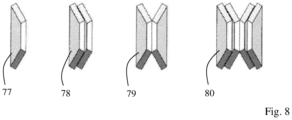
- Fig. 8 shows a single cup spring 77, cup springs in parallel 78 i.e. cup springs laid one on the other, cup springs in series 79 i.e. cup springs laid one against another and a combination of cup springs in series and cup springs in parallel 80. All these formations have different spring characteristic.
- the cup springs in a formation may be of identical dimensions but it is feasible to stack numbers of cup springs with different thickness in order to achieve a stepped spring characteristic. For example, cup springs with increasing thickness may be stacked to receive progressive spring characteristics.
- cup springs When cup springs are used in the fuel tank attaching structure in fig. 5 the cup springs may be stacked according to what is shown in fig. 8 or in any other way suitable for the application in question. In one preferred embodiment, for example the one in fig. 6 , the cup springs may be stacked in series and parallel 80. Such a combination may consist of six packages 85,86,87,88,89,90 each including 10 cup springs in parallel, which packages are arranged in series. Such a combination may have a length of 40-100 mm.
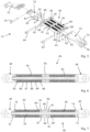
- Fig 4 and 6 shows the tensioning device 46 when the gas tanks 4 are in their contracted phase and surrounded by the tensioning strap 7.
- the gap 50 between the first fastening element 48 and the second fastening 49 may be relatively small or absent.
- the spring means 59 brings about a suitable holding force in the longitudinal direction of the tensioning strap 7 to the gas tanks 4.
- the holding force may be 30-45 kN.
- the first fastening element 48 and the second fastening element 49 moves away from one another in the longitudinal direction of the connecting element 70.
- the gap 50 expands as can be seen in fig 7 and the spring means 59 are pressed together and absorbs the expansion so that the tensioning strap 7 can enlarge its diameter to fasten the gas tanks 4 as before the expansion.
- the number of shanks 60 and the number of spring means 59 may vary depending on the forces required to keep the tanks in place.
Landscapes
- Engineering & Computer Science (AREA)
- Mechanical Engineering (AREA)
- Life Sciences & Earth Sciences (AREA)
- Sustainable Development (AREA)
- Sustainable Energy (AREA)
- Chemical & Material Sciences (AREA)
- Combustion & Propulsion (AREA)
- Transportation (AREA)
- General Engineering & Computer Science (AREA)
- Cooling, Air Intake And Gas Exhaust, And Fuel Tank Arrangements In Propulsion Units (AREA)
- Filling Or Discharging Of Gas Storage Vessels (AREA)
Claims (11)
- Struktur zum Anbringen eines Kraftstofftanks (5) an einem Kraftfahrzeug (1) mit wenigstens einem daran befestigten expandierbaren und zusammenziehbaren Kraftstofftank (4), um darin komprimiertes Gas zu speichern, wobei die Struktur zum Anbringen eines Kraftstofftanks (5) wenigstens eine Halterung (8) umfasst, die dazu ausgebildet ist, an einem Fahrzeugfahrgestell (2) fixiert zu werden, um den wenigstens einen Kraftstofftank (4) und den wenigstens einen Spanngurt (7) zu stützen, der dazu ausgebildet ist, um den Kraftstofftank (4) herum befestigt zu werden und dazu ausgebildet ist, den Kraftstofftank (4) an der Halterung (8) zu befestigen, wobei der Spanngurt (7) ein erstes Ende (24) und ein zweites Ende (32) umfasst, zwischen denen eine Spannvorrichtung (46) dazu ausgebildet ist, eine Haltekraft des Spanngurts (7) auf den Kraftstofftank (4) anzuwenden, dadurch gekennzeichnet, dass die Spannvorrichtung (46) wenigstens ein erstes Befestigungselement (48), das dazu ausgebildet ist, mit dem ersten Ende (24) des Spanngurts (7) und einem Querstück (61) verbunden zu werden, der eine erste Oberfläche (68) und eine zweite Oberfläche (69) aufweist, wenigstens ein zweites Befestigungselement (49), das dazu ausgebildet ist, mit dem zweiten Ende (32) des Spanngurts (7) und einem weiteren Querstück (61) verbunden zu werden, der eine erste Oberfläche (68) und eine zweite Oberfläche (69) aufweist, wobei das erste Befestigungselement (48) und das zweite Befestigungselement (49) dazu ausgebildet sind, so angeordnet zu werden, dass ihre ersten Oberflächen (68) einander zugewandt sind, wenigstens ein Verbindungselement (70), das darauf ausgelegt ist, sich verlagerbar durch ein Loch (67) in jedem Querstück (61) zwischen dem ersten Befestigungselement (48) und dem zweiten Befestigungselement (49) zu erstrecken, ein erstes Befestigungselement (72), das dazu ausgebildet ist, mit einem ersten Ende des Befestigungselements (70), einem zweiten Befestigungselement (73), das dazu ausgebildet ist, mit einem zweiten Ende des Befestigungselements (70) und einer Federungseinrichtung (59), die dazu ausgebildet ist, sich zwischen dem ersten Befestigungselement (72) und der zweiten Oberfläche (69) und zwischen dem zweiten Befestigungselement (73) und der zweiten Oberfläche (69) zu erstrecken, verbunden zu werden, umfasst, wobei die Federungseinrichtung (59) dazu ausgebildet ist, unabhängig davon, ob sich die Kraftstofftanks (4) in einem expandierten oder zusammengezogenen Zustand befinden, eine Haltekraft des Spanngurts (7) auf die Kraftstofftanks (4) auszuüben, indem das erste Befestigungselement (48) und das zweite Befestigungselement (49) in Längsrichtung des Verbindungselements (70) bewegt werden können.
- Struktur zum Anbringen eines Kraftstofftanks (5) nach Anspruch 1, dadurch gekennzeichnet, dass das erste Befestigungselement (48) und das zweite Befestigungselement (49) gabelförmig sind und wenigstens zwei Schenkel (60) umfassen, die voneinander beabstandet sind und durch ein Querstück (61) miteinander verbunden sind, wobei die Schenkel (60) dazu ausgebildet sind, sich zumindest teilweise entlang der entsprechenden Schenkel (82) am ersten Ende (24) und am zweiten Ende (32) zu erstrecken und and ihren freien Enden Durchgangsbohrungen (63) umfassen, die dazu ausgebildet sind, mit den entsprechenden Durchgangsbohrungen (83) am ersten Ende (24) und am zweiten Ende (32) ausgerichtet zu sein, wobei die Stifte (64, 65) dazu ausgebildet sind, sich durch die Löcher (63, 83) zu erstrecken, um das erste Befestigungselement (48) mit dem ersten Ende (24) zu verbinden und das zweite Befestigungselement (49) mit dem zweiten Ende (32) zu verbinden.
- Struktur zum Anbringen eines Kraftstofftanks (5) nach Anspruch 2, dadurch gekennzeichnet, dass die Schenkel (60) und das Querstück (61) einen U-förmigen Bereich (62) definieren, durch den sich die Federungseinrichtung (59) erstreckt.
- Struktur zum Anbringen eines Kraftstofftanks (5) nach Anspruch 1 oder 2, dadurch gekennzeichnet, dass das erste Befestigungselement (48) schwenkbar mit dem ersten Ende (24) verbunden ist und dass das zweite Befestigungselement (49) schwenkbar mit dem zweiten Ende (32) verbunden ist.
- Struktur zum Anbringen eines Kraftstofftanks (5) nach Anspruch 1, dadurch gekennzeichnet, dass die Spannvorrichtung (46) dazu ausgebildet ist, sich in Längsrichtung des Spanngurts (7) zu erstrecken.
- Struktur zum Anbringen eines Kraftstofftanks (5) nach Anspruch 1, dadurch gekennzeichnet, dass der Spanngurt (7) in einen ersten Gurtteil (14) und einen zweiten Gurtteil (15) unterteilt ist und dass die Spannvorrichtung (46) sowohl am ersten Gurtteil (14) als auch am zweiten Gurtteil (15) vorgesehen ist.
- Struktur zum Anbringen eines Kraftstofftanks (5) nach Anspruch 1, dadurch gekennzeichnet, dass die Federungseinrichtung (59) koaxial um das Verbindungselement (70) angeordnet ist.
- Struktur zum Anbringen eines Kraftstofftanks (5) nach Anspruch 7, dadurch gekennzeichnet, dass die Federungseinrichtung (59) eine Anzahl von Tellerfedern (77) umfasst, die aufeinandergestapelt sind.
- Struktur zum Anbringen eines Kraftstofftanks (5) nach Anspruch 8, dadurch gekennzeichnet, dass die Tellerfedern (77) der Reihe nach und im Wesentlichen parallel (84) relativ zueinander aufeinandergestapelt sind.
- Struktur zum Anbringen eines Kraftstofftanks (5) nach Anspruch 8, dadurch gekennzeichnet, dass die Länge der Federungseinrichtung (59) 40-100 mm beträgt.
- Kraftfahrzeug (1) umfassend eine Struktur zum Anbringen eines Kraftstofftanks (5) nach einem der Ansprüche 1-10.
Applications Claiming Priority (2)
| Application Number | Priority Date | Filing Date | Title |
|---|---|---|---|
| SE1651100A SE540129C2 (en) | 2016-08-11 | 2016-08-11 | A fuel tank attachment structure for a motor vehicle |
| PCT/SE2017/050642 WO2018030931A1 (en) | 2016-08-11 | 2017-06-15 | A fuel tank attaching structure for a motor vehicle |
Publications (3)
| Publication Number | Publication Date |
|---|---|
| EP3496966A1 EP3496966A1 (de) | 2019-06-19 |
| EP3496966A4 EP3496966A4 (de) | 2020-04-22 |
| EP3496966B1 true EP3496966B1 (de) | 2024-10-09 |
Family
ID=61163223
Family Applications (1)
| Application Number | Title | Priority Date | Filing Date |
|---|---|---|---|
| EP17839919.2A Active EP3496966B1 (de) | 2016-08-11 | 2017-06-15 | Kraftstofftankbefestigungsstruktur für ein kraftfahrzeug |
Country Status (5)
| Country | Link |
|---|---|
| EP (1) | EP3496966B1 (de) |
| KR (1) | KR102185177B1 (de) |
| CN (1) | CN109562689B (de) |
| SE (1) | SE540129C2 (de) |
| WO (1) | WO2018030931A1 (de) |
Families Citing this family (12)
| Publication number | Priority date | Publication date | Assignee | Title |
|---|---|---|---|---|
| DE102016015645A1 (de) * | 2016-12-30 | 2018-07-05 | Man Truck & Bus Ag | Spannband, insbesondere zur Befestigung eines Gegenstands an einem Fahrzeug |
| DE102018117356A1 (de) * | 2018-07-18 | 2020-01-23 | Man Truck & Bus Se | Nutzfahrzeug oder Nutzfahrzeuggespann mit Wasserstoffdruckspeicher |
| JP7103250B2 (ja) * | 2019-01-31 | 2022-07-20 | トヨタ自動車株式会社 | 燃料電池車両 |
| CN114761269A (zh) | 2019-12-11 | 2022-07-15 | 沃尔沃卡车集团 | 用于组装车辆的储箱组件的方法 |
| EP4011669B1 (de) | 2020-12-11 | 2025-06-25 | Volvo Truck Corporation | Energiespeicherkammer |
| FR3125753A1 (fr) | 2021-07-27 | 2023-02-03 | Faurecia Systemes D'echappement | Dispositif de fixation d’un réservoir à un véhicule |
| SE546868C2 (en) * | 2021-11-25 | 2025-03-04 | Scania Cv Ab | Fastening Device and Vehicle |
| EP4331887A1 (de) | 2022-09-01 | 2024-03-06 | Scania CV AB | Befestigungsvorrichtung und gasbrennstoffspeicheranordnung sowie fahrzeug und verfahren |
| FR3146884A1 (fr) * | 2023-03-24 | 2024-09-27 | Hutchinson | Dispositif d’attache de plaques auto-obturantes contre la paroi externe d’un réservoir, ensemble muni d’un tel dispositif d’attache et procédé de montage associé |
| AU2024201745A1 (en) * | 2023-03-24 | 2024-10-10 | Hutchinson | Attachment device for attaching self-sealing plates to the external wall of a tank, assembly equipped with such an attachment device and associated mounting method |
| EP4563385A1 (de) | 2023-11-28 | 2025-06-04 | Volvo Truck Corporation | Kraftstoffspeicheranordnung für ein kraftfahrzeug |
| EP4674662A1 (de) * | 2024-07-03 | 2026-01-07 | On-Highway Brasil Ltda. | Verbessertes lastträgersystem für ein fahrzeug |
Family Cites Families (14)
| Publication number | Priority date | Publication date | Assignee | Title |
|---|---|---|---|---|
| DE3215723A1 (de) * | 1982-04-28 | 1983-11-03 | Eisen-und Drahtwerk Erlau AG, 7080 Aalen | Anschlussteil fuer eine spannvorrichtung zum spannen von gurten, ketten und dgl., vorzugsweise fuer eine ratsche |
| US5013182A (en) * | 1989-04-04 | 1991-05-07 | Donaldson Company, Inc. | Self-adjusting mounting-band assembly |
| US5308101A (en) * | 1992-07-20 | 1994-05-03 | Monty Corp. | Elastically retractable automobile towing strap |
| DE19721253C2 (de) * | 1997-05-21 | 1999-05-12 | Man Nutzfahrzeuge Ag | Spannband für Fahrzeugbehälter |
| CA2290259A1 (en) * | 1999-11-22 | 2001-05-22 | Rene Rutz | Restraining strap for securing pressure vessels |
| KR100453655B1 (ko) * | 2001-12-27 | 2004-10-20 | 현대자동차주식회사 | 트럭용 연료탱크의 스트랩 마운팅 구조 |
| JP2004237766A (ja) * | 2003-02-03 | 2004-08-26 | Fuji Heavy Ind Ltd | 車両のガス燃料タンク取付構造 |
| KR100612753B1 (ko) * | 2004-11-05 | 2006-08-21 | 현대자동차주식회사 | 상용차용 연료탱크의 장착 구조 |
| DE102006026118A1 (de) * | 2006-06-03 | 2007-12-06 | GM Global Technology Operations, Inc., Detroit | Befestigungsanordnung für Gastank eines Kraftfahrzeugs |
| DE102006028498B4 (de) * | 2006-06-21 | 2016-04-14 | Elringklinger Ag | Brennstoffzellenstapel |
| ITTO20070159A1 (it) * | 2007-03-02 | 2008-09-03 | Fiat Group Automobiles Spa | Collare per il supporto ed il trattenimento di oggetti, in particolare per il supporto ed il trattenimento di serbatoi di gas combustibile |
| DE102012004319A1 (de) * | 2012-03-03 | 2013-09-05 | Volkswagen Aktiengesellschaft | Vorrichtung für die Befestigung eines Spannbandes eines Tanks |
| CA2809250C (en) * | 2013-03-15 | 2014-10-21 | Westport Power Inc. | Tank support apparatus and method |
| JP6112102B2 (ja) * | 2014-12-12 | 2017-04-12 | トヨタ自動車株式会社 | 燃料タンク及び燃料タンク製造方法 |
-
2016
- 2016-08-11 SE SE1651100A patent/SE540129C2/en unknown
-
2017
- 2017-06-15 CN CN201780048653.9A patent/CN109562689B/zh active Active
- 2017-06-15 WO PCT/SE2017/050642 patent/WO2018030931A1/en not_active Ceased
- 2017-06-15 KR KR1020197004787A patent/KR102185177B1/ko active Active
- 2017-06-15 EP EP17839919.2A patent/EP3496966B1/de active Active
Also Published As
| Publication number | Publication date |
|---|---|
| CN109562689A (zh) | 2019-04-02 |
| CN109562689B (zh) | 2022-01-25 |
| KR102185177B1 (ko) | 2020-12-01 |
| EP3496966A4 (de) | 2020-04-22 |
| KR20190027921A (ko) | 2019-03-15 |
| BR112019000945A2 (pt) | 2019-04-30 |
| WO2018030931A1 (en) | 2018-02-15 |
| SE540129C2 (en) | 2018-04-03 |
| SE1651100A1 (en) | 2018-02-12 |
| EP3496966A1 (de) | 2019-06-19 |
Similar Documents
| Publication | Publication Date | Title |
|---|---|---|
| EP3496966A1 (de) | Kraftstofftankbefestigungsstruktur für ein kraftfahrzeug | |
| US10583747B2 (en) | Vehicle battery system with a plurality of straps | |
| US6557814B1 (en) | Restraining strap for securing pressure vessels | |
| US20090278292A1 (en) | Multi-axis spring damping system for a payload in a spacecraft | |
| US20090114784A1 (en) | Fuel tank mounting arrangement and method of mounting a fuel tank | |
| US8215444B2 (en) | Roll restrictor system for an automotive powertrain | |
| RU2498152C2 (ru) | Удерживающее устройство для удерживания газового резервуара автомобиля и автомобиль с таким устройством | |
| EP3383688A1 (de) | Befestigungsanordnung für ein bandförmiges spannband | |
| US20090226793A1 (en) | Fuel cell stack assembly | |
| SE540795C2 (en) | A gas fuel storage assembly | |
| WO2018030930A1 (en) | A fuel tank attaching structure for a motor vehicle | |
| CN213892169U (zh) | 一种车载气瓶的捆绑装置 | |
| CN106553695B (zh) | 自卸车及其主副车架联接装置 | |
| EP2891198B1 (de) | Befestigungssystem für eine batterie in einem fahrzeug | |
| CN118019944A (zh) | 紧固装置和车辆 | |
| US9956868B1 (en) | Storage container with improved mounting assembly | |
| JP5576624B2 (ja) | 車両用荷台支持装置 | |
| CN222905472U (zh) | 管线束支架组件和具有其的车辆 | |
| RU68432U1 (ru) | Устройство для крепления цистерны к раме шасси | |
| US20260042345A1 (en) | Fastening device and gas fuel storage assembly and vehicle and method | |
| DE202006019006U1 (de) | Befestigungseinrichtung für mindestens eine Kraftstoffflasche in oder an einem Fahrzeug | |
| US20210347314A1 (en) | Clamping Strap for Mounting a Component | |
| CN119617298A (zh) | 一种车用cng气瓶的固定装置 | |
| BR112019000945B1 (pt) | Estrutura de acoplamento de tanque de combustível para um veículo motor e veículo motor |
Legal Events
| Date | Code | Title | Description |
|---|---|---|---|
| STAA | Information on the status of an ep patent application or granted ep patent |
Free format text: STATUS: THE INTERNATIONAL PUBLICATION HAS BEEN MADE |
|
| PUAI | Public reference made under article 153(3) epc to a published international application that has entered the european phase |
Free format text: ORIGINAL CODE: 0009012 |
|
| STAA | Information on the status of an ep patent application or granted ep patent |
Free format text: STATUS: REQUEST FOR EXAMINATION WAS MADE |
|
| 17P | Request for examination filed |
Effective date: 20190311 |
|
| AK | Designated contracting states |
Kind code of ref document: A1 Designated state(s): AL AT BE BG CH CY CZ DE DK EE ES FI FR GB GR HR HU IE IS IT LI LT LU LV MC MK MT NL NO PL PT RO RS SE SI SK SM TR |
|
| AX | Request for extension of the european patent |
Extension state: BA ME |
|
| DAV | Request for validation of the european patent (deleted) | ||
| DAX | Request for extension of the european patent (deleted) | ||
| A4 | Supplementary search report drawn up and despatched |
Effective date: 20200325 |
|
| RIC1 | Information provided on ipc code assigned before grant |
Ipc: B60K 15/07 20060101ALI20200319BHEP Ipc: F16G 11/12 20060101ALI20200319BHEP Ipc: B60K 15/067 20060101AFI20200319BHEP |
|
| RAP3 | Party data changed (applicant data changed or rights of an application transferred) |
Owner name: SCANIA CV AB |
|
| STAA | Information on the status of an ep patent application or granted ep patent |
Free format text: STATUS: EXAMINATION IS IN PROGRESS |
|
| 17Q | First examination report despatched |
Effective date: 20220411 |
|
| P01 | Opt-out of the competence of the unified patent court (upc) registered |
Effective date: 20230516 |
|
| GRAP | Despatch of communication of intention to grant a patent |
Free format text: ORIGINAL CODE: EPIDOSNIGR1 |
|
| STAA | Information on the status of an ep patent application or granted ep patent |
Free format text: STATUS: GRANT OF PATENT IS INTENDED |
|
| INTG | Intention to grant announced |
Effective date: 20240516 |
|
| GRAS | Grant fee paid |
Free format text: ORIGINAL CODE: EPIDOSNIGR3 |
|
| GRAA | (expected) grant |
Free format text: ORIGINAL CODE: 0009210 |
|
| STAA | Information on the status of an ep patent application or granted ep patent |
Free format text: STATUS: THE PATENT HAS BEEN GRANTED |
|
| AK | Designated contracting states |
Kind code of ref document: B1 Designated state(s): AL AT BE BG CH CY CZ DE DK EE ES FI FR GB GR HR HU IE IS IT LI LT LU LV MC MK MT NL NO PL PT RO RS SE SI SK SM TR |
|
| REG | Reference to a national code |
Ref country code: CH Ref legal event code: EP |
|
| REG | Reference to a national code |
Ref country code: DE Ref legal event code: R096 Ref document number: 602017085417 Country of ref document: DE |
|
| REG | Reference to a national code |
Ref country code: IE Ref legal event code: FG4D |
|
| REG | Reference to a national code |
Ref country code: LT Ref legal event code: MG9D |
|
| REG | Reference to a national code |
Ref country code: NL Ref legal event code: MP Effective date: 20241009 |
|
| REG | Reference to a national code |
Ref country code: AT Ref legal event code: MK05 Ref document number: 1730234 Country of ref document: AT Kind code of ref document: T Effective date: 20241009 |
|
| PG25 | Lapsed in a contracting state [announced via postgrant information from national office to epo] |
Ref country code: NL Free format text: LAPSE BECAUSE OF FAILURE TO SUBMIT A TRANSLATION OF THE DESCRIPTION OR TO PAY THE FEE WITHIN THE PRESCRIBED TIME-LIMIT Effective date: 20241009 |
|
| PG25 | Lapsed in a contracting state [announced via postgrant information from national office to epo] |
Ref country code: NL Free format text: LAPSE BECAUSE OF FAILURE TO SUBMIT A TRANSLATION OF THE DESCRIPTION OR TO PAY THE FEE WITHIN THE PRESCRIBED TIME-LIMIT Effective date: 20241009 |
|
| PG25 | Lapsed in a contracting state [announced via postgrant information from national office to epo] |
Ref country code: HR Free format text: LAPSE BECAUSE OF FAILURE TO SUBMIT A TRANSLATION OF THE DESCRIPTION OR TO PAY THE FEE WITHIN THE PRESCRIBED TIME-LIMIT Effective date: 20241009 Ref country code: PT Free format text: LAPSE BECAUSE OF FAILURE TO SUBMIT A TRANSLATION OF THE DESCRIPTION OR TO PAY THE FEE WITHIN THE PRESCRIBED TIME-LIMIT Effective date: 20250210 Ref country code: IS Free format text: LAPSE BECAUSE OF FAILURE TO SUBMIT A TRANSLATION OF THE DESCRIPTION OR TO PAY THE FEE WITHIN THE PRESCRIBED TIME-LIMIT Effective date: 20250209 |
|
| PG25 | Lapsed in a contracting state [announced via postgrant information from national office to epo] |
Ref country code: FI Free format text: LAPSE BECAUSE OF FAILURE TO SUBMIT A TRANSLATION OF THE DESCRIPTION OR TO PAY THE FEE WITHIN THE PRESCRIBED TIME-LIMIT Effective date: 20241009 |
|
| PG25 | Lapsed in a contracting state [announced via postgrant information from national office to epo] |
Ref country code: BG Free format text: LAPSE BECAUSE OF FAILURE TO SUBMIT A TRANSLATION OF THE DESCRIPTION OR TO PAY THE FEE WITHIN THE PRESCRIBED TIME-LIMIT Effective date: 20241009 |
|
| PG25 | Lapsed in a contracting state [announced via postgrant information from national office to epo] |
Ref country code: ES Free format text: LAPSE BECAUSE OF FAILURE TO SUBMIT A TRANSLATION OF THE DESCRIPTION OR TO PAY THE FEE WITHIN THE PRESCRIBED TIME-LIMIT Effective date: 20241009 |
|
| PG25 | Lapsed in a contracting state [announced via postgrant information from national office to epo] |
Ref country code: NO Free format text: LAPSE BECAUSE OF FAILURE TO SUBMIT A TRANSLATION OF THE DESCRIPTION OR TO PAY THE FEE WITHIN THE PRESCRIBED TIME-LIMIT Effective date: 20250109 |
|
| PG25 | Lapsed in a contracting state [announced via postgrant information from national office to epo] |
Ref country code: LV Free format text: LAPSE BECAUSE OF FAILURE TO SUBMIT A TRANSLATION OF THE DESCRIPTION OR TO PAY THE FEE WITHIN THE PRESCRIBED TIME-LIMIT Effective date: 20241009 Ref country code: GR Free format text: LAPSE BECAUSE OF FAILURE TO SUBMIT A TRANSLATION OF THE DESCRIPTION OR TO PAY THE FEE WITHIN THE PRESCRIBED TIME-LIMIT Effective date: 20250110 Ref country code: AT Free format text: LAPSE BECAUSE OF FAILURE TO SUBMIT A TRANSLATION OF THE DESCRIPTION OR TO PAY THE FEE WITHIN THE PRESCRIBED TIME-LIMIT Effective date: 20241009 |
|
| PG25 | Lapsed in a contracting state [announced via postgrant information from national office to epo] |
Ref country code: PL Free format text: LAPSE BECAUSE OF FAILURE TO SUBMIT A TRANSLATION OF THE DESCRIPTION OR TO PAY THE FEE WITHIN THE PRESCRIBED TIME-LIMIT Effective date: 20241009 |
|
| PG25 | Lapsed in a contracting state [announced via postgrant information from national office to epo] |
Ref country code: RS Free format text: LAPSE BECAUSE OF FAILURE TO SUBMIT A TRANSLATION OF THE DESCRIPTION OR TO PAY THE FEE WITHIN THE PRESCRIBED TIME-LIMIT Effective date: 20250109 |
|
| PG25 | Lapsed in a contracting state [announced via postgrant information from national office to epo] |
Ref country code: SM Free format text: LAPSE BECAUSE OF FAILURE TO SUBMIT A TRANSLATION OF THE DESCRIPTION OR TO PAY THE FEE WITHIN THE PRESCRIBED TIME-LIMIT Effective date: 20241009 |
|
| PGFP | Annual fee paid to national office [announced via postgrant information from national office to epo] |
Ref country code: DE Payment date: 20250429 Year of fee payment: 9 |
|
| PG25 | Lapsed in a contracting state [announced via postgrant information from national office to epo] |
Ref country code: DK Free format text: LAPSE BECAUSE OF FAILURE TO SUBMIT A TRANSLATION OF THE DESCRIPTION OR TO PAY THE FEE WITHIN THE PRESCRIBED TIME-LIMIT Effective date: 20241009 |
|
| PGFP | Annual fee paid to national office [announced via postgrant information from national office to epo] |
Ref country code: GB Payment date: 20250501 Year of fee payment: 9 |
|
| REG | Reference to a national code |
Ref country code: DE Ref legal event code: R097 Ref document number: 602017085417 Country of ref document: DE |
|
| PGFP | Annual fee paid to national office [announced via postgrant information from national office to epo] |
Ref country code: BE Payment date: 20250516 Year of fee payment: 9 |
|
| PG25 | Lapsed in a contracting state [announced via postgrant information from national office to epo] |
Ref country code: EE Free format text: LAPSE BECAUSE OF FAILURE TO SUBMIT A TRANSLATION OF THE DESCRIPTION OR TO PAY THE FEE WITHIN THE PRESCRIBED TIME-LIMIT Effective date: 20241009 |
|
| PGFP | Annual fee paid to national office [announced via postgrant information from national office to epo] |
Ref country code: FR Payment date: 20250508 Year of fee payment: 9 |
|
| PG25 | Lapsed in a contracting state [announced via postgrant information from national office to epo] |
Ref country code: RO Free format text: LAPSE BECAUSE OF FAILURE TO SUBMIT A TRANSLATION OF THE DESCRIPTION OR TO PAY THE FEE WITHIN THE PRESCRIBED TIME-LIMIT Effective date: 20241009 |
|
| PG25 | Lapsed in a contracting state [announced via postgrant information from national office to epo] |
Ref country code: SK Free format text: LAPSE BECAUSE OF FAILURE TO SUBMIT A TRANSLATION OF THE DESCRIPTION OR TO PAY THE FEE WITHIN THE PRESCRIBED TIME-LIMIT Effective date: 20241009 |
|
| PG25 | Lapsed in a contracting state [announced via postgrant information from national office to epo] |
Ref country code: CZ Free format text: LAPSE BECAUSE OF FAILURE TO SUBMIT A TRANSLATION OF THE DESCRIPTION OR TO PAY THE FEE WITHIN THE PRESCRIBED TIME-LIMIT Effective date: 20241009 |
|
| PG25 | Lapsed in a contracting state [announced via postgrant information from national office to epo] |
Ref country code: IT Free format text: LAPSE BECAUSE OF FAILURE TO SUBMIT A TRANSLATION OF THE DESCRIPTION OR TO PAY THE FEE WITHIN THE PRESCRIBED TIME-LIMIT Effective date: 20241009 |
|
| PLBE | No opposition filed within time limit |
Free format text: ORIGINAL CODE: 0009261 |
|
| STAA | Information on the status of an ep patent application or granted ep patent |
Free format text: STATUS: NO OPPOSITION FILED WITHIN TIME LIMIT |
|
| PG25 | Lapsed in a contracting state [announced via postgrant information from national office to epo] |
Ref country code: SE Free format text: LAPSE BECAUSE OF FAILURE TO SUBMIT A TRANSLATION OF THE DESCRIPTION OR TO PAY THE FEE WITHIN THE PRESCRIBED TIME-LIMIT Effective date: 20241009 |
|
| 26N | No opposition filed |
Effective date: 20250710 |
|
| REG | Reference to a national code |
Ref country code: CH Ref legal event code: H13 Free format text: ST27 STATUS EVENT CODE: U-0-0-H10-H13 (AS PROVIDED BY THE NATIONAL OFFICE) Effective date: 20260127 |
|
| PG25 | Lapsed in a contracting state [announced via postgrant information from national office to epo] |
Ref country code: MC Free format text: LAPSE BECAUSE OF FAILURE TO SUBMIT A TRANSLATION OF THE DESCRIPTION OR TO PAY THE FEE WITHIN THE PRESCRIBED TIME-LIMIT Effective date: 20241009 |
|
| PG25 | Lapsed in a contracting state [announced via postgrant information from national office to epo] |
Ref country code: LU Free format text: LAPSE BECAUSE OF NON-PAYMENT OF DUE FEES Effective date: 20250615 |
|
| PG25 | Lapsed in a contracting state [announced via postgrant information from national office to epo] |
Ref country code: IE Free format text: LAPSE BECAUSE OF NON-PAYMENT OF DUE FEES Effective date: 20250615 |
|
| PG25 | Lapsed in a contracting state [announced via postgrant information from national office to epo] |
Ref country code: CH Free format text: LAPSE BECAUSE OF NON-PAYMENT OF DUE FEES Effective date: 20250630 |