EP3496641B1 - Devices for delivering fluid to tissue during ablation therapy - Google Patents
Devices for delivering fluid to tissue during ablation therapy Download PDFInfo
- Publication number
- EP3496641B1 EP3496641B1 EP17840018.0A EP17840018A EP3496641B1 EP 3496641 B1 EP3496641 B1 EP 3496641B1 EP 17840018 A EP17840018 A EP 17840018A EP 3496641 B1 EP3496641 B1 EP 3496641B1
- Authority
- EP
- European Patent Office
- Prior art keywords
- elongate body
- outlet ports
- fluid
- flow
- tissue
- Prior art date
- Legal status (The legal status is an assumption and is not a legal conclusion. Google has not performed a legal analysis and makes no representation as to the accuracy of the status listed.)
- Active
Links
Images


Classifications
-
- A—HUMAN NECESSITIES
- A61—MEDICAL OR VETERINARY SCIENCE; HYGIENE
- A61B—DIAGNOSIS; SURGERY; IDENTIFICATION
- A61B18/00—Surgical instruments, devices or methods for transferring non-mechanical forms of energy to or from the body
- A61B18/04—Surgical instruments, devices or methods for transferring non-mechanical forms of energy to or from the body by heating
- A61B18/12—Surgical instruments, devices or methods for transferring non-mechanical forms of energy to or from the body by heating by passing a current through the tissue to be heated, e.g. high-frequency current
- A61B18/14—Probes or electrodes therefor
- A61B18/1477—Needle-like probes
-
- A—HUMAN NECESSITIES
- A61—MEDICAL OR VETERINARY SCIENCE; HYGIENE
- A61B—DIAGNOSIS; SURGERY; IDENTIFICATION
- A61B18/00—Surgical instruments, devices or methods for transferring non-mechanical forms of energy to or from the body
- A61B18/04—Surgical instruments, devices or methods for transferring non-mechanical forms of energy to or from the body by heating
- A61B18/12—Surgical instruments, devices or methods for transferring non-mechanical forms of energy to or from the body by heating by passing a current through the tissue to be heated, e.g. high-frequency current
- A61B18/14—Probes or electrodes therefor
- A61B18/1492—Probes or electrodes therefor having a flexible, catheter-like structure, e.g. for heart ablation
-
- A—HUMAN NECESSITIES
- A61—MEDICAL OR VETERINARY SCIENCE; HYGIENE
- A61B—DIAGNOSIS; SURGERY; IDENTIFICATION
- A61B18/00—Surgical instruments, devices or methods for transferring non-mechanical forms of energy to or from the body
- A61B2018/00315—Surgical instruments, devices or methods for transferring non-mechanical forms of energy to or from the body for treatment of particular body parts
- A61B2018/00345—Vascular system
- A61B2018/00351—Heart
-
- A—HUMAN NECESSITIES
- A61—MEDICAL OR VETERINARY SCIENCE; HYGIENE
- A61B—DIAGNOSIS; SURGERY; IDENTIFICATION
- A61B18/00—Surgical instruments, devices or methods for transferring non-mechanical forms of energy to or from the body
- A61B2018/00571—Surgical instruments, devices or methods for transferring non-mechanical forms of energy to or from the body for achieving a particular surgical effect
- A61B2018/00577—Ablation
-
- A—HUMAN NECESSITIES
- A61—MEDICAL OR VETERINARY SCIENCE; HYGIENE
- A61B—DIAGNOSIS; SURGERY; IDENTIFICATION
- A61B18/00—Surgical instruments, devices or methods for transferring non-mechanical forms of energy to or from the body
- A61B2018/00636—Sensing and controlling the application of energy
- A61B2018/00696—Controlled or regulated parameters
- A61B2018/00714—Temperature
-
- A—HUMAN NECESSITIES
- A61—MEDICAL OR VETERINARY SCIENCE; HYGIENE
- A61B—DIAGNOSIS; SURGERY; IDENTIFICATION
- A61B18/00—Surgical instruments, devices or methods for transferring non-mechanical forms of energy to or from the body
- A61B2018/00636—Sensing and controlling the application of energy
- A61B2018/00696—Controlled or regulated parameters
- A61B2018/00744—Fluid flow
-
- A—HUMAN NECESSITIES
- A61—MEDICAL OR VETERINARY SCIENCE; HYGIENE
- A61B—DIAGNOSIS; SURGERY; IDENTIFICATION
- A61B18/00—Surgical instruments, devices or methods for transferring non-mechanical forms of energy to or from the body
- A61B18/04—Surgical instruments, devices or methods for transferring non-mechanical forms of energy to or from the body by heating
- A61B2018/044—Surgical instruments, devices or methods for transferring non-mechanical forms of energy to or from the body by heating the surgical action being effected by a circulating hot fluid
- A61B2018/046—Surgical instruments, devices or methods for transferring non-mechanical forms of energy to or from the body by heating the surgical action being effected by a circulating hot fluid in liquid form
-
- A—HUMAN NECESSITIES
- A61—MEDICAL OR VETERINARY SCIENCE; HYGIENE
- A61B—DIAGNOSIS; SURGERY; IDENTIFICATION
- A61B18/00—Surgical instruments, devices or methods for transferring non-mechanical forms of energy to or from the body
- A61B18/04—Surgical instruments, devices or methods for transferring non-mechanical forms of energy to or from the body by heating
- A61B18/12—Surgical instruments, devices or methods for transferring non-mechanical forms of energy to or from the body by heating by passing a current through the tissue to be heated, e.g. high-frequency current
- A61B18/14—Probes or electrodes therefor
- A61B2018/1472—Probes or electrodes therefor for use with liquid electrolyte, e.g. virtual electrodes
-
- A—HUMAN NECESSITIES
- A61—MEDICAL OR VETERINARY SCIENCE; HYGIENE
- A61B—DIAGNOSIS; SURGERY; IDENTIFICATION
- A61B2218/00—Details of surgical instruments, devices or methods for transferring non-mechanical forms of energy to or from the body
- A61B2218/001—Details of surgical instruments, devices or methods for transferring non-mechanical forms of energy to or from the body having means for irrigation and/or aspiration of substances to and/or from the surgical site
- A61B2218/002—Irrigation
Definitions
- This disclosure relates generally to surgical instruments and, more particularly, to such instruments that deliver fluid to tissue in connection with ablation therapy.
- Fluid enhanced ablation therapy involves the introduction of a fluid into a volume of tissue to deliver a therapeutic dose of energy in order to destroy tissue.
- the fluid can act as a therapeutic agent delivering thermal energy into the tissue volume-thermal energy supplied from the fluid itself (e.g., a heated fluid) or from an ablation element that provides thermal energy using, e.g., radio frequency (RF) electrical energy, microwave or light wave electromagnetic energy, ultrasonic vibrational energy, etc.
- RF radio frequency
- fluid enhanced ablation therapy is the ablation technique described in U.S. Patent No. 6,328,735 .
- saline is passed through a needle and heated, and the heated fluid is delivered into a target volume of tissue surrounding the needle.
- RF electrical current is simultaneously passed through the tissue between an emitter electrode positioned on the needle and a remotely located return electrode.
- the saline acts as a therapeutic agent to transport thermal energy to the target volume of tissue via convection, and the RF electrical energy can act to supplement and/or replenish the thermal energy of the fluid that is lost as it moves through the tissue.
- the delivery of thermal energy via the movement of fluid through tissue can allow a greater volume of tissue to be treated with a therapeutic dose of ablative energy than is possible with other known techniques.
- the therapy is usually completed once the target volume of tissue reaches a desired therapeutic temperature, or otherwise receives a therapeutic dose of energy.
- Fluid enhanced ablation therapy can have a number of advantages over, e.g., conventional RF ablation techniques.
- the delivery of fluid in combination with RF energy can more effectively convect the heat developed near the RF electrode into the surrounding tissue. This can prevent tissue adjacent to the RF electrode from charring and desiccating due to the accumulation of too much thermal energy near the electrode.
- this charring can occur in tissue near the electrode even after only a short amount of time. Tissue charring can be problematic because it is accompanied by an increase in tissue impedance that can prevent the transmission of RF energy through the tissue, thereby effectively ending the therapy. Localized overheating of tissue can also cause so-called "steam pops," which are explosive phase changes of liquid contained in tissue. If the fluid has a higher conductivity than the surrounding tissue, the volume rate of deposition of RF energy immediately adjacent to the RF electrode can be reduced somewhat, further decreasing the risks of charring and desiccation adjacent to the RF electrode.
- fluid be delivered into tissue wherever RF or other ablative energy is being delivered.
- an electrode or other energy delivery element often extends proximally from the one or more openings and there can be a misalignment between the RF or other energy field and the fluid distribution field.
- a lack of fluid delivery along an entire length of, for example, an ablation electrode or other portion of a device intended to deliver thermal energy and fluid can reduce the effectiveness of the therapy and lead to potential complications for a patient.
- US6080151 discloses an ablation catheter having proximal and distal ends and an external surface, a lumen contained within the catheter body, a plurality of openings in the surface of the catheter, wherein the openings are in communication with the lumen, one or more electrodes secured within the catheter within the lumen and a source for conductive media to be introduced into the lumen to contact the electrode.
- the present disclosure generally provides devices and methods for delivering fluid to tissue during ablation therapy, including, for example, during fluid enhanced ablation therapy procedures.
- the devices and methods described herein generally provide a more uniform distribution-or a desired non-uniform distribution-of fluid flow from a plurality of outlet ports formed in, for example, an elongate body of an ablation device. Because the plurality of outlet ports are positioned to create a desired fluid flow pattern in tissue, where such a pattern optimizes the performance of the ablation therapy, providing uniform or desired flow from each of the outlet ports can ensure the therapy proceeds as intended and is as efficient as possible.
- Adding or otherwise adjusting flow resistance can include adjusting either or both of resistance to fluid flow per unit length of lumen and resistance to fluid flow from an elongate body lumen into tissue surrounding the elongate body.
- the devices and methods described herein can include increasing levels of flow resistance to fluid flow from a plurality of outlet ports.
- such resistance can vary from a proximal to a distal end of a portion of an elongate body or other device that includes such outlet ports.
- such resistance can increase from the proximal to the distal end of the portion of the elongate body or other device that includes the outlet ports.
- a resistance per unit length of lumen/elongate body to fluid flow through the lumen/elongate body can similarly be increased, and can increase along a length of the elongate body from a proximal to a distal end thereof. While counter to typical intuition that reduced flow resistance via, e.g., increased outlet port numbers, sizes, etc. would allow for increased flow, the addition of flow resistance can ensure there is sufficient fluid pressure near each outlet port to cause fluid to flow therefrom.
- Increasing flow resistance along a length of an elongate body or other ablation device can be accomplished in a number of manners.
- the number, size, shape, orientation, and positioning of the plurality of outlet ports can be adjusted to provide better flow from all or a subset of the outlet ports. This can mean, for example, decreasing a size of outlet ports formed more distally along an elongate body or other ablation device, while increasing or maintaining a size of outlet ports formed more proximally.
- relative spacing between adjacent outlet ports, or pitch of a series of outlet ports arranged around an elongate body can be adjusted to provide fewer outlet ports along a distal portion of an elongate body and more outlet ports along a proximal portion thereof.
- the number, size, and shape of the plurality of outlet ports can be adjusted to maintain a ratio of the cumulative or combined area of the outlet ports (i.e., a sum of the cross-sectional areas of each of the plurality of outlet ports) to the area of the inner lumen (i.e., the cross-sectional area through which fluid can flow, sometimes referred to herein as inner lumen cross-sectional flow area) at or below a certain level. For example, it can be desirable to maintain this ratio below a level of about 3:1 to maintain desired fluid flow from all outlet ports.
- the cross-sectional area of an inner lumen delivering fluid to the outlet ports can be reduced from a proximal to a distal end thereof to increase flow resistance therewithin.
- a tapered flow diverter or other structure can be disposed within an inner lumen of an elongate body or other device in the vicinity of the outlet ports.
- a diameter of the inner lumen can decrease from a proximal portion of an elongate body or other device to a distal portion thereof via, for example, tapered sidewalls of varying thickness. Accordingly, the area of the inner lumen at a particular point, or the volume of a selected portion of the inner lumen, can reduce as one moves distally along a device.
- ablation devices can be constructed that provide improved distribution of fluid from a plurality of outlet ports.
- an ablation device can be constructed wherein no more than about 70% by volume of fluid delivered to tissue is emitted from the distal-most 25% of outlet ports on the device.
- no more than about 70% by volume of the fluid delivered to tissue is emitted from the proximal-most 25% of outlet ports.
- any desired fluid flow distribution can be created, for example, a distribution in which no more than 33% by volume of fluid delivered to tissue is emitted from a distal-most 25% of outlet ports on the device.
- fluid distribution patterns can be selected so as to produce any desired percentage of fluid flow by volume from any desired group of outlet ports, e.g., no more than 50% by volume of fluid delivered from a distal-most 30% of outlet ports, etc.
- any desired percentage of fluid flow by volume e.g., no more than 50% by volume of fluid delivered from a distal-most 30% of outlet ports, etc.
- the almost complete distal-port flow bias observed in prior art devices can be avoided by producing a significant amount of fluid flow from one or more outlet ports disposed along a proximal portion of fluid delivery region of a device.
- an ablation device can include an elongate body having an inner lumen and a plurality of outlet ports formed in the elongate body that are disposed along a length thereof.
- the plurality of outlet ports can be configured to deliver fluid from the inner lumen to tissue surrounding the elongate body.
- the device can further include an ablation element configured to heat the tissue surrounding the elongate body.
- a flow resistance of the elongate body can increase along the length of the elongate body containing the plurality of outlet ports from a proximal end thereof to a distal end thereof.
- the flow resistance of the elongate body can include any of a flow resistance per unit length of lumen and a resistance to fluid flow from the lumen through any outlet ports into, for example, tissue surrounding the elongate body. Adjusting either or both of these parameters can effect a change in flow resistance of the elongate body.
- a ratio of a sum of an area of each of the plurality of outlet ports to an area of the inner lumen can be less than about 3:1.
- a cross-sectional area of each of the plurality of outlet ports can decrease from a proximal end of the elongate body to a distal end of the elongate body.
- a diameter of the outlet ports can decrease from a proximal end of the elongate body to a distal end thereof.
- spacing between adjacent axially-aligned outlet ports e.g., adjacent outlet ports aligned with one another along an axis parallel to a longitudinal axis of the elongate body
- At least one of the plurality of outlet ports can have a non-circular shape.
- at least one of the plurality of outlet ports can have a slot shape. Any number of other shapes are also possible, including hybrids of slots (e.g., tapered slots, etc.), circles, and other shapes.
- a diameter of the inner lumen can decrease along the length of the elongate body containing the plurality of outlet ports from a proximal end thereof to a distal end thereof.
- tapered elongate body sidewalls of varying thickness can be used to create such a narrowing of the diameter of the inner lumen from a proximal to a distal end thereof.
- the device can further include a flow diverter disposed within the inner lumen of the elongate body along the length of the elongate body containing the plurality of outlet ports.
- the flow diverter can serve to reduce the cross-sectional area of the inner lumen and thereby increase flow resistance per unit length of lumen to fluid flow.
- the flow diverter can, for example, increase in diameter from a proximal end thereof to a distal end thereof.
- a flow diverter can be combined with, for example, tapered elongate body sidewalls of varying thickness to further reduce cross-sectional flow area over at least a portion of the length of the elongate body.
- the ablation element can be any of a variety of ablation elements known in the art and configured to deliver ablative energy to surrounding tissue.
- the ablation element can be a radio frequency electrode disposed along a length of the elongate body, such as a ring of conductive material disposed over a non-conductive elongate body or a portion of a conductive elongate body that is left uncovered by an electrically insulating material.
- the device can further include at least one outlet port positioned at least partially beyond a boundary of the ablation element to deliver fluid to tissue immediately adjacent to the boundary of the ablation element.
- one or more outlet ports can be positioned across or adjacent to a boundary of the ablation element. Placing outlet ports on or near an electrode or other ablation element boundary, including at locations at least partially beyond the boundary, can serve to counteract increased current density, and attendant heating, that can occur in areas adjacent to ablation element boundaries.
- an ablation device in another aspect, includes an elongate body having an inner lumen, the elongate body including a fluid delivery portion extending along a length thereof that includes a plurality of outlet ports configured to deliver fluid from the inner lumen to tissue surrounding the elongate body.
- the device can further include an ablation element configured to heat tissue surrounding the elongate body.
- the fluid delivery portion of the elongate body can be configured such that less than about 70% by volume of fluid delivered to tissue is emitted from outlet ports disposed in a distal 25% of the fluid delivery portion.
- the fluid delivery portion can be further configured such that less than about 55% by volume of fluid delivered to tissue is emitted from outlet ports disposed in a distal 25% of the fluid delivery portion In other embodiments, the fluid delivery portion can be further configured such that less than about 70% by volume of fluid delivered to tissue is emitted from outlet ports disposed in a proximal 25% of the fluid delivery portion. In still other embodiments, the fluid delivery portion can be further configured such that less than about 55% by volume of fluid delivered to tissue is emitted from outlet ports disposed in a proximal 25% of the fluid delivery portion. In yet other embodiments, the fluid delivery portion can be further configured such that no more than about 70% by volume of fluid delivered to tissue is emitted from outlet ports disposed in a central 50% of the fluid delivery portion.
- any desired predetermined fluid distribution pattern is possible, with any desired percentage of fluid by volume being delivered from any desired subset of outlet ports formed in the elongate body.
- the fluid delivery portion can be configured such that less than a predetermined percentage by volume of fluid delivered to tissue is emitted from outlet ports disposed in a predetermined portion of the elongate body or outlet ports formed therein.
- the predetermined percentage can be, for example, 25%, 35%, 50%, 70%, or other values in certain embodiments, and the predetermined portion of the elongate body or outlet ports can be a distal 25%, 30%, 35%, etc., a proximal 25%, 30%, 35%, etc., a central 50%, 60%, 70%, etc. It can be desirable in some embodiments to avoid a strong flow bias in any one portion of the elongate body configured to deliver fluid to tissue, e.g., a proximal portion, distal portion, or central portion.
- an ablation device in still another aspect, includes a catheterdelivered elongate body having an inner lumen and a plurality of outlet ports formed in the elongate body, each of the plurality of outlet ports defining an area configured to pass fluid from the inner lumen to tissue surrounding the elongate body.
- the device can further include an ablation element configured to heat the tissue surrounding the elongate body.
- a ratio of a sum of the areas of each of the plurality of outlet ports to an area of the inner lumen can be less than about 3:1.
- the ratio of the sum of the areas of each of the plurality of outlet ports to the area of the inner lumen can be less than about 2.5:1. In other embodiments, the ratio of the sum of the areas of each of the plurality of outlet ports to the area of the inner lumen can be less than about 2:1. More particularly, in some embodiments the ratio of the sum of the areas of each of the plurality of outlet ports to the area of the inner lumen can be less than about 1.3:1. In still other embodiments, the ratio of the sum of the areas of each of the plurality of outlet ports to the area of the inner lumen can be between about 0.5:1 and about 2:1, or the equivalent of 1 x / ⁇ 2 (1 times or divide by 2).
- a cross-sectional area of the inner lumen through which fluid can flow can decrease from a proximal end to a distal end of a length of the elongate body that includes the plurality of outlet ports. In some embodiments, this can be accomplished via a diameter of the inner lumen that decreases from the proximal end to the distal end of the length of the elongate body that includes the plurality of outlet ports. In other embodiments, this can be accomplished via a flow diverter disposed within the inner lumen of the elongate body along the length of the elongate body that includes the plurality of outlet ports.
- a diameter of the flow diverter can increase from a proximal end thereof to a distal end thereof, thereby progressively reducing the cross-sectional area of the inner lumen available for fluid flow.
- varying a cross-sectional flow area of the inner lumen can be combined with selection of outlet port size to achieve the various ratios mentioned above and further enhance the flow resistance to flow within the inner lumen that can produce uniform fluid delivery from all of the outlet ports.
- any of a number of surface features or other variations can be incorporated into the flow diverter to create localized changes in fluid flow.
- the flow diverter can include any of at least one step to transition from a first diameter to a second diameter and at least one recess.
- a step (or steps) can create a localized change in fluid flow by further restricting the cross-sectional area through which fluid can flow and by introducing an abrupt change in direction to fluid flow.
- a recess formed in the flow diverter can create a localized change in fluid flow by increasing the cross-sectional area through which fluid can flow and reducing the fluid pressure experienced near the recess.
- a step (or steps) or recess (or recesses) can be positioned anywhere along the flow diverter but, in some embodiments, can be aligned with one of the plurality of outlet ports formed in the elongate body. Positioning a step, recess, or other feature of the flow diverter in alignment with one of the plurality of outlet ports can create localized changes in flow (e.g., an increase or decrease) from that particular outlet port.
- the device can further include a thermocouple positioned at a proximal end of the flow diverter. In still other embodiments, the device can further include a heating element positioned at a proximal end of the flow diverter and configured to heat fluid flowing within the inner lumen.
- the inner lumen through which the fluid can flow can also include a fluid heater that heats the fluid as it flows through the fluid delivery system.
- linear or circular dimensions are used in the description of the disclosed devices and methods, such dimensions are not intended to limit the types of shapes that can be used in conjunction with such devices and methods. Equivalents to such linear and circular dimensions can easily be determined for any geometric shape. Further, in the present disclosure, like-numbered components of the embodiments generally have similar features. Still further, sizes and shapes of the devices, and the components thereof, can depend at least on the anatomy of the subject in which the devices will be used, the size and shape of components with which the devices will be used, and the methods and procedures in which the devices will be used.
- Fluid enhanced ablation therapy is defined by passing a fluid into tissue to act as a therapeutic agent and deliver thermal energy into the tissue.
- the thermal energy can be provided from the fluid itself (e.g., by using heated fluid), by delivering therapeutic energy from an ablation element (e.g., an RF electrode), or a combination of the two.
- the delivery of therapeutic energy into tissue can cause hyperthermia in the tissue, ultimately resulting in necrosis.
- This temperature-induced selective destruction of tissue can be utilized to treat a variety of conditions including tumors, fibroids, cardiac dysrhythmias (e.g., ventricular tachycardia, etc.), and others.
- the ablation technique described in U.S. Patent No. 6,328,735 delivers fluid heated to a therapeutic temperature into tissue along with ablative energy.
- the heated fluid acts as a therapeutic agent by flowing through the extracellular space of the treatment tissue and increasing the heat transfer through the tissue significantly.
- the flowing heated fluid convects thermal energy into the target tissue.
- the thermal energy can be supplied from the heated fluid itself and the ablation energy source can act to replenish thermal energy lost from the fluid as it moves through the tissue.
- the fluid can serve to constantly hydrate the tissue and prevent any tissue charring and associated impedance rise near the ablation element, as described in more detail below.
- the fluid can regulate the temperature of the tissue and prevent localized overheating that can cause, for example, so-called "steam pops," which are the explosive phase change of liquid in the tissue.
- Fluid enhanced ablation therapy can have a number of advantages over prior art ablation techniques, such as conventional RF ablation.
- conventional RF ablation often overheats the tissue located adjacent to the emitter electrode because the heat cannot be efficiently transported away from the electrode. This overheating can cause charring of the tissue and an associated rise in impedance that can effectively terminate the therapy.
- the therapeutically heated fluid can convect heat deeper into the target tissue, thereby reducing tissue charring and the associated impedance change of the tissue. Further, because the fluid is heated to a therapeutic level, it does not act as a heat sink that draws down the temperature of the surrounding tissue.
- the fluid itself acts as the therapeutic agent delivering thermal energy into the tissue and the RF energy can act to counter the loss of thermal energy from the fluid as it moves through the tissue. Therefore, the concurrent application of RF energy and injection of heated fluid into the tissue can eliminate the desiccation and/or vaporization of tissue adjacent to the electrode, maintain the effective tissue impedance, and increase the thermal transport within the tissue being heated with RF energy. The total volume of tissue that can be heated to therapeutic temperatures is thereby increased when compared to conventional RF ablation.
- fluid enhanced ablation therapy devices have a greater number of parameters that can be varied to adjust the shape of the treated volume of tissue.
- an operator or control system can modify parameters such as fluid temperature (e.g., from about 40° C to about 100° C), fluid flow rate (e.g., from about 0 ml/min to about 50 ml/min), RF power ( e.g., from about 0 W to about 200 W), and duration of treatment (e.g., from about 0 min to about 10 min) to adjust the temperature profile within the target volume of tissue.
- the composition, ionic content, and dissolved oxygen content of the delivered fluid can also be varied to improve effectiveness of thermal energy delivery within the target tissue.
- an emitter electrode can be configured as a continuous cylindrical band around a needle or other elongate body, or the electrode can be formed in other geometries, such as spherical or helical.
- the electrode can form a continuous surface area, or it can have a plurality of discrete portions.
- electrodes in monopolar or bipolar configurations can be utilized. Further examples of how a treated volume of tissue can be selectively shaped by varying the parameters of fluid enhanced ablation therapy can be found in U.S. Patent No. 8,702,697 , entitled "Devices and Methods for Shaping Therapy in Fluid Enhanced Ablation".
- FIG. 1 illustrates a diagram of one embodiment of a fluid enhanced ablation system 100.
- the system includes an elongate body 102 configured for insertion into a target volume of tissue.
- the elongate body can have a variety of shapes and sizes according to the geometry of the target tissue. Further, the particular size of the elongate body can depend on a variety of factors including the type and location of tissue to be treated, the size of the tissue volume to be treated, etc.
- the elongate body can be a thin-walled stainless steel needle between about 16- and about 18-gauge ( i.e., an outer diameter of about 1.27 mm to about 1.65 mm), and having a length that is approximately 25 cm.
- the elongate body 102 can include a pointed distal tip 104 configured to puncture tissue to facilitate introduction of the device into a target volume of tissue, however, in other embodiments the tip can be blunt and can have various other configurations.
- the elongate body 102 can be formed from a conductive material such that the elongate body can conduct electrical energy along its length to one or more ablation elements located along a distal portion of the elongate body.
- Emitter electrode 105 is an example of an ablation element capable of delivering RF energy from the elongate body.
- the emitter electrode 105 can be a portion of the elongate body 102.
- the elongate body 102 can be coated in an insulating material along its entire length except for the portion representing the emitter electrode 105.
- the elongate body 102 can be coated with 0.038 mm (1.5 mil) of the fluoropolymer Xylan TM 8840.
- different coatings can be used in place of, or in conjunction with, the fluoropolymer coating.
- 1 mil of Polyester shrink tubing can be disposed over the Xylan coating.
- the electrode 105 can have a variety of lengths and shape configurations.
- the electrode 105 can be a 4 mm section of a tubular elongate body that is exposed to surrounding tissue. Further, the electrode 105 can be located anywhere along the length of the elongate body 105 (and there can also be more than one electrode disposed along the length of the elongate body). In one embodiment, the electrode can be located adjacent to the distal tip 104. In other embodiments, the elongate body can be formed from an insulating material, and the electrode can be disposed around the elongate body or between portions of the elongate body, e.g., as a conductive metal ring surrounding a polymer elongate body, etc.
- the electrode can be formed from a variety of materials suitable for conducting current. Any metal or metal salt may be used. Aside from stainless steel, exemplary metals include platinum, gold, or silver, and exemplary metal salts include silver/silver chloride. In one embodiment, the electrode can be formed from silver/silver chloride. It is known that metal electrodes assume a voltage potential different from that of surrounding tissue and/or liquid. Passing a current through this voltage difference can result in energy dissipation at the electrode/tissue interface, which can exacerbate excessive heating of the tissue near the electrodes.
- a metal salt such as silver/silver chloride is that it has a high exchange current density.
- an electrode formed from a metal salt such as silver/silver chloride can reduce excessive energy generation at the tissue interface and thereby produce a more desirable therapeutic temperature profile, even where there is no liquid flow about the electrode.
- the ablation element included in a fluid enhanced ablation therapy device can be configured to deliver a variety of types of energy into tissue surrounding the device.
- An ablation element such as the electrode 105, that is configured to deliver RF electrical energy is just one example of an ablation element that can be utilized with the methods and devices described herein.
- an alternative ablation element configured to deliver microwave electromagnetic energy is described in U.S. Patent No. 9,033,972 , entitled "Methods and Devices for Fluid Enhanced Microwave Ablation Therapy".
- Other exemplary ablation elements can be configured to deliver, for example, any type of electrical energy, electromagnetic energy, or ultrasonic vibrational energy.
- the electrode 105 or other ablation element, or other portion of the elongate body 102 can include one or more outlet ports 108 that are configured to deliver fluid from an inner lumen 106 extending through the elongate body into surrounding tissue (as shown by arrows 109).
- the outlet ports 108 can be formed in a variety of sizes, numbers, and pattern configurations.
- the outlet ports 108 can be configured to direct fluid in a variety of directions with respect to the elongate body 102.
- the elongate body 102 can be formed with an open distal end that serves as an outlet port. Further details of the outlet ports 108 are discussed below.
- the inner lumen 106 that communicates with the outlet ports 108 can also house a heating assembly 110 configured to heat fluid as it passes through the inner lumen 106 just prior to being introduced into tissue.
- the heating assembly 110 can have a variety of configurations and, in one embodiment, can include two wires suspended within the inner lumen 106. The wires can be configured to pass RF energy therebetween in order to heat fluid flowing through the inner lumen 106. In other embodiments, a single wire can be configured to pass RF energy between the wire and the inner walls of the elongate body. Further description of exemplary heating assemblies can be found in U.S. Pat. Pub. No. 2012/0265190, entitled "Methods and Devices for Heating Fluid in Fluid Enhanced Ablation Therapy ".
- the portion of the elongate body located distal to the electrode 105 or other ablation element can be solid or filled such that the inner lumen 106 terminates at the distal end of the electrode 105.
- the inner volume of the portion of the elongate body distal to the electrode can be filled with a plastic plug that can be epoxied in place or held by an interference fit.
- the portion of the elongate body distal to the electrode can be formed from solid metal and attached to the proximal portion of the elongate body by welding, swaging, or any other technique known in the art.
- the elongate body can include one or more outlet ports formed at or near a distal end thereof. Such outlet ports can be formed through a plastic plug or other element described above that may be disposed near a distal end of the elongate body, or an opening can be provided in place of such an element.
- Such a device is just one exemplary embodiment of a medical device that can be adapted for use in fluid enhanced ablation therapy, however.
- a very small elongate body can be required when treating cardiac dysrhythmias, such as ventricular tachycardia.
- an appropriately sized needle or other elongate body can be, for example, disposed at a distal end of a catheter configured for insertion into the heart via the circulatory system.
- a stainless steel needle body between about 20- and about 30-gauge (i.e., an outer diameter of about 0.3 mm to about 0.9 mm) can be disposed at a distal end of a catheter.
- the catheter can have a variety of sizes but, in some embodiments, it can have a length of about 120 cm and a diameter of about 8 French ("French” is a unit of measure used in the catheter industry to describe the size of a catheter and is equal to three times the diameter of the catheter in millimeters).
- Other variations can include, for example, a low profile form factor for use in space-constrained environments and the inclusion of additional components, such as one or more temperature sensors to monitor the temperature of tissue in the treatment volume. Further details on these exemplary features can be found in U.S. Pat. Pub. No. 2014/0052117 , entitled “Low Profile Fluid Enhanced Ablation Therapy Devices and Methods," as well as U.S. Pat. Pub. No. 2012/0277737, entitled “Devices and Methods for Remote Temperature Monitoring in Fluid Enhanced Ablation Therapy. "
- an exemplary fluid source is shown as a fluid reservoir 112.
- the fluid reservoir 112 can have a variety of geometries and sizes.
- the fluid reservoir 112 can be a cylindrical container similar to a syringe barrel that can be used with a linear pump, as described below.
- the fluid reservoir 112 can be connected to the inner lumen 106 via a fluid conduit 114 to supply fluid to the inner lumen and heating assembly 110.
- the fluid conduit 114 can be, for example, a length of flexible plastic tubing.
- the fluid conduit 114 can also be a rigid tube, or a combination of rigid and flexible tubing.
- a fluid used in the fluid reservoir 112 can be selected to provide the desired therapeutic and physical properties when applied to the target tissue, and a sterile fluid is recommended to guard against infection of the tissue.
- a preferred fluid for use in fluid-enhanced RF ablation is sterile normal saline solution (defined as a salt-containing solution).
- the fluid can be modified to enhance the effectiveness of the therapy. For example, in some embodiments dissolved gasses can be removed from the fluid prior to use, a contrast agent can be added to the fluid to make it imageable using a medical imaging technology, or the ionic content of the fluid can otherwise be modified to enhance conductivity of the surrounding tissue. Further details on these exemplary features can be found in U.S. Patent. No.
- Fluid can be urged from the fluid reservoir 112 into the inner lumen 106 by a pump 116.
- the pump 116 can be a syringe-type pump that produces a fixed volume flow via linear advancement of a plunger (not shown). In other embodiments, however, other types of pumps, such as a diaphragm pump, may also be employed.
- the pump 116 can be controlled by a controller 118.
- the controller 118 can include a power supply 119 and can be configured to deliver electrical control signals to the pump 116 to cause the pump to produce a desired flow rate of fluid.
- the controller 118 can be connected to the pump 116 via an electrical connection 120.
- the controller 118 can also include an interface for receiving lead wires or other connecting elements to electrically couple the controller 118 to the elongate body 102 and one or more return electrodes 124.
- These electrical connections which can have any desired length and can utilize any known electrical connecting elements to interface with the controller 118 (e.g., plugs, alligator clips, rings, prongs, etc.), are illustrated in FIG. 1 as connections 122 and 126.
- the controller 118 can be connected to the heating assembly 110 through a similar electrical connection, as described below.
- the return electrode 124 can have a variety of forms.
- the return electrode 124 can be a single large electrode located outside a patient's body.
- the return electrode 124 can be a return electrode located elsewhere along the elongate body 102, or it can be located on a second elongate body introduced into a patient's body near the treatment site.
- one or more outlet ports can be included in the return electrode as well to provide enhanced fluid flow to the tissue surrounding the return electrode.
- the return electrode 124 can be designed to receive current emitted from the ablation element 105, thereby completing the circuit back to the controller 118 through the electrical connection 126.
- the controller 118 can drive the delivery of fluid into target tissue at a desired flow rate, the heating of the fluid to a desired therapeutic temperature, and the delivery of therapeutic ablative energy via the one or more ablation elements, such as electrode 105.
- the controller 118 can itself comprise a number of components for generating, regulating, and delivering required electrical control and therapeutic energy signals.
- the controller 118 can include one or more digital data processors and associated storage memories that can be configured to perform a variety of functions, or control discrete circuit elements that perform a given function. These functions can include, for example, the generation of one or more electrical signals of various frequencies and amplitudes.
- FIGS. 2A and 2B illustrate one embodiment of an ideal flow pattern in which a spherical flow of fluid 202 is created around an elongate body 204. Note that the ideal spherical flow 202 extends in every direction around a distal portion of the elongate body 204 that can include an ablation element. Accordingly, a central source of ablative energy can be concentrically located with the outlet ports 206 that originate the fluid flow 202.
- Tissue inside this volume can be treated with therapeutic levels of thermal energy, while also being constantly hydrated and regulated such that overheating (e.g., so-called "steam pops," which can occur when fluid in tissue is heated above 100°C) and desiccation do not occur.
- overheating e.g., so-called "steam pops," which can occur when fluid in tissue is heated above 100°C
- desiccation do not occur.
- large volumes of tissue can be treated efficiently without requiring repositioning of the device.
- FIG. 3 depicts one embodiment of an elongate body of the type described in these patents and publications and shows that it suffers from a distally-biased fluid flow pattern.
- Such a pattern likely performs better than a simple open distal end, but nevertheless suffers from insufficient proximal fluid flow that can result in overheating (e.g., steam pops), dehydration, and impedance rises in tissue adj acent to proximal portions of the elongate body.
- FIG. 3 is a photograph of an elongate body of the type described in U.S. Patent No. 6,328,735 delivering fluid into air at a flow rate of about 50 ml/min. This flow rate is relatively high, but was utilized to achieve the streams shown in the photograph, as at lower flow rates in air fluid can appear to simply drip out of the distal end of the elongate body. As shown in FIG. 3 , significant flow is achieved only from the distal-most outlet ports formed in the elongate body, indeed, nearly 100% of the fluid flow by volume is emitted from a distal-most 25% of outlet ports formed in the elongate body. Further details regarding this elongate body and its outlet port configuration are provided below and shown in FIG. 21 .
- the pattern of outlet ports shown in FIG. 3 extends for approximately 4 mm, but only the distal-most 1 mm of outlet ports are producing significant fluid flow. As described above, this can mean that the tissue adjacent to the proximal 3 mm of outlet ports is insufficiently hydrated during therapy. Indeed, investigation into repeated occurrence of impedance rises and overheating in tissue adjacent to a proximal portion of an elongate body or ablation element led the applicants of the present disclosure to discover the depicted distally-biased flow.
- an elongate body of the same configuration was introduced into a bath of 37° C saline and fluid containing an ultraviolet (UV) dye was delivered through the device.
- UV ultraviolet
- a distal outlet port bias remained evident, with very low fluid flow velocity coming from the proximal outlet ports of the elongate body.
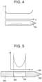
- FIG. 4 illustrates one embodiment of an elongate body 402 that is formed from a conductive material and configured to deliver RF electrical energy into tissue.
- the elongate body 402 can be, for example, the above-described stainless steel needle disposed at a distal end of a catheter and configured to treat ventricular tachycardia with fluid enhanced ablation therapy.
- the entire elongate body can be the ablation element, as current can be passed from the elongate body through surrounding tissue to a collector electrode disposed remotely from the elongate body.
- the current density J emitted from the elongate body can spike near the distal tip and proximal end of the elongate body, and can be largely constant along its constant-diameter length. Accordingly, if fluid is hydrating tissue and regulating the temperature thereof only near a distal end of the elongate body 402, tissue adjacent a more proximal portion of the elongate body could easily overheat and dehydrate.
- FIG. 5 illustrates one embodiment of an elongate body 502 that includes an ablation element 504 disposed along, or made up from, only a portion of the elongate body.
- an ablation element 504 disposed along, or made up from, only a portion of the elongate body.
- Such a device can be, for example, covered in an electrically insulating shielding 506 along all but a portion of its length.
- the exposed portion of conductive steel can be utilized as the ablation element 504 in the form of, again, an RF electrode.
- the graph of FIG. 5 illustrates the current density J along the length of the elongate body 502. Note that the current density rises significantly at the edges, or boundaries, of the ablation element 504. This significant increase in current density can be particularly problematic for the proximal boundary 508 of the ablation element 504 if insufficient fluid is delivered at this location. This is especially true because the heating experienced in adjacent tissue is related to the square of the illustrated current density.
- Flow resistance can also refer to resistance to fluid flow from an elongate body lumen into tissue surrounding the elongate body, e.g., resistance to flow through one or more outlet ports.
- the idea that adding flow resistance to the elongate body would create more uniform flow from all outlet ports was unexpected, as it runs counter to the intuitive response to the problem.
- flow resistance can be increased by reducing the number of outlet ports formed in the elongate body, by reducing the area of each port or changing their shape, or by otherwise adding features to the inner lumen of the elongate body to increase flow resistance.
- These modifications can all function to increase fluid pressure within the inner lumen along a length of the elongate body that contains the outlet ports.
- Another way to think of the increased flow resistance is in terms of fluid stall pressure-the goal being to stall fluid flow farther back into the elongate body proximally beyond the location of all outlet ports. Doing so can result in fluid flowing out uniformly from all of the outlet ports, or in a predetermined non-uniform manner if so desired.
- FIG. 6 illustrates one embodiment of an elongate body according to the teachings of the present disclosure delivering fluid into air at a same flow rate as the elongate body depicted in FIG. 3 .
- the additional flow resistance resulting from selection of outlet port size in relation to inner lumen size can produce the uniform flow from each outlet port shown in FIG. 6 .
- FIGS. 7A and 7B illustrate two embodiments of an elongate body 902, 904 and how the ratio can be applied.
- the ratio can be calculated by summing the area of each outlet port 906 (i.e., summing the cross-sectional area of the eight outlet ports visible in the figure plus the area of any outlet ports hidden from view) and comparing it to the area of the inner lumen 908.
- the cross-sectional area of the inner lumen 908 can be taken at a point of maximum diameter or, in some embodiments, at a point just proximal to the proximal-most outlet port (in many embodiments, the elongate body can have a maximum diameter at the point just proximal to the proximal-most outlet port).
- this ratio can be kept below about 3:1. In some embodiments, the ratio can be kept below about 2.5:1, while in other embodiments the ratio can be kept below about 2:1. In certain embodiments, the ratio can be kept between about 0.5:1 and about 2:1, which is roughly equivalent to the mathematical relationship of 1 x / ⁇ 2 (1 times or divide by 2).
- the ratio for the elongate bodies of the type disclosed in the prior art and depicted in FIG. 3 is on the order of 6:1, far above the range set out above that can ensure proper fluid flow distribution.
- the ratio can hold true regardless of the configuration of outlet ports found in the device.
- the ratio can be maintained with the elongate body 904 of FIG. 7B , despite the fact that a large distal end opening 910 is present in addition to the plurality of outlet ports 906.
- the cross-sectional area of the opening 910 can be added to the cross-sectional areas of the outlet ports 906. So long as the ratio of this total outlet area to the cross-sectional area of the inner lumen 912 remains below about 3:1, fluid should flow from each outlet port 906 and the opening 910.
- FIG. 8 illustrates one embodiment of an elongate body 1002 with a plurality of outlet ports 1004-1016 having varying sizes and relative spacing.
- a diameter of the outlet port 1004 is larger than a diameter of any more distal outlet port 1006-1016.
- outlet ports 1004-1016 their relative spacing (e.g., as measured axially along a longitudinal axis of the elongate body, angularly around a circumference of the elongate body, or combinations thereof) can also be varied along a length of the elongate body 1002.
- this variation can be inverse to the variation described above with respect to outlet port diameter or size.
- spacing between adjacent outlet ports or successive rows of outlet ports spaced around an elongate body can increase from a proximal end of the elongate body 1002 to a distal end thereof.
- the distance D 1 can be less than any distance D 2 -D 6 positioned distally thereof.
- Such an arrangement clusters additional (and possibly larger) outlet ports near a proximal end of the elongate body 1002, thereby promoting flow in this area and building additional fluid pressure in a distal portion of the inner lumen.
- FIG. 8 illustrates a single row of axially aligned outlet ports 1004-1016, but outlet ports can often be created by forming a series of through-holes (thereby creating two opposed outlet ports) at angular and axial offsets from one another, as shown by FIGS. 21, 22 , 24 , and 26 , described in more detail below.
- the angular offset of outlet ports can also be varied to further adjust the pattern and distribution of fluid flow.
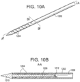
- FIG. 9A illustrates one embodiment of an elongate body 1102 having an ablation element 1104, such as an RF electrode, disposed along a length thereof and bounded at proximal and distal ends.
- Ablation element boundaries can be created in a number of manners, including, for example, with electrically insulating shielding 1106 disposed around the elongate body along its proximal and distal ends.
- a plurality of outlet ports 1110 are formed in the ablation element 1104 and a current density along a length of the ablation element 1104 can be similar to the current density depicted in FIG. 5 .
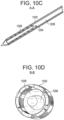
- the diverter 1206 can be positioned within the inner lumen 1208 such that it is concentric with the inner lumen, as shown in FIGS. 10C and 10D .
- the flow diverter 1206 is attached to the elongate body 1202 at its distal end 1210, which, as described above, can be a solid terminus in certain embodiments.
- the flow diverter 1206 can be formed from a variety of materials and its dimensions can be largely influenced by the elongate body into which it fits.
- the flow diverter can be formed from stainless steel in the same manner as the elongate body.
- the flow diverter 1206 can be utilized as a mounting location for one or more sensors to monitor characteristics of the flow within the inner lumen 1208.
- a thermocouple 1212 can be positioned at a proximal end of the flow diverter and can monitor the temperature of saline or other fluid just before it is delivered to tissue through the outlet ports.
- the heating assembly 110 described above can also be positioned at the proximal end of the flow diverter.
- steps can be strategically positioned in some embodiments to provide desired flow characteristics.
- steps can be placed wherever more forceful delivery of fluid is desired. This can include, for example, placing steps to aid in biasing a flow pattern toward a proximal end of the elongate body. This is one example, however, as a number of other flow pattern shapes can be achieved by varying the placement of steps or other surface features on a flow diverter.
- steps 1310 need not be symmetrical or uniform along the length or circumference of the flow diverter 1306.
- localized features such as steps, ridges, bumps, cones, pins, etc. can be formed on the surface of the flow diverter 1306.
- a plurality of smaller flow diverters can be formed on sidewalls of the inner lumen of the elongate body 1302, e.g., just proximally of individual outlet ports 1304.
- the flow diverter 1306 can include a winding form, such as a helix or screw thread.
- the flow diverter 1306 or inner lumen sidewalls can include features to selectively reduce pressure and flow output.
- one or more recesses formed in the flow diverter 1306 can cause a localized pressure drop which, if aligned with an outlet port, can cause flow through the outlet port to be reduced.
- Such recesses can be utilized in some embodiments to accumulate fluid whose flow is being controlled farther downstream in the device (i.e., distally of the recess or recesses).
- such recesses or other pressure reduction features can be used in combination with steps or other features to create turbulence within the fluid flow. This can be useful, for example, to enhance fluid mixing and distribute energy delivered to the fluid from a heating element (e.g., heating assembly 110 described above).
- FIG. 12 illustrates one embodiment of an elongate body 1402 that includes tapered sidewalls 1404 that progressively increase in thickness from a proximal end to a distal end of the portion of the elongate body containing outlet ports 1406.
- the taper of the sidewalls 1404 can reduce the diameter, and hence the cross-sectional area of the inner lumen 1408 of the elongate body 1402 toward a distal end thereof, thereby increasing fluid pressure within the inner lumen in the same manner as the flow diverter pins discussed above.
- Any number of the features discussed above, including steps, ridges, or other protrusions, as well as recesses or other pressure reduction features, can be formed on the tapered sidewalls 1404 in the same manner as the flow diverters 1206, 1306.
- outlet flow distribution can be modified by adjusting the size and spacing of the ports themselves, as well as by including one or more flow diverting features within an inner lumen of an elongate body. It can also be desirable in some cases to adjust the shape of the outlet ports in order to further modify the flow distribution pattern.
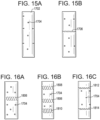
- FIG. 13 illustrates a front view of one example of an elongate body 1502 of the type described above.
- the elongate body 1502 (a distal end of which is visible in the figure) can include a plurality of outlet ports that are circular in shape and spaced around the circumference of the elongate body.
- the flow distribution pattern can appear like a wheel hub having a number of spokes or cones 1504 of fluid extending therefrom.
- This distribution pattern can include gaps 1506 between adjacent cones of fluid 1504.
- gaps 1506 can be undesirable. This is because tissue in the gaps 1506 can receive relatively lower amounts of fluid than tissue directly in the path of the fluid 1504. In addition, tissue in the path of the fluid 1504 can experience elevated pressure from the strong flow passing directly therethrough.
- FIG. 14 illustrates one embodiment of fluid flow that can result if outlet ports are slot-shaped, rather than circular.
- a distal end of an elongate body 1602 is visible, along with a plurality of fan-shaped fluid flows 1604 extending therefrom. More specifically, this embodiment makes use of two staggered rows of six slots. The length of the slots, as well as the degree of overlap between slots in different rows can be adjusted to minimize the number of gaps present in the flow pattern.
- FIG. 16A illustrates an alternative embodiment of a slot-shaped outlet port 1806 in which an S-curve shape is utilized.
- FIGS. 16B and 16C similarly illustrate possible combinations of multiple rows of slot-shaped outlet ports 1808-1814 in relation to circular (or other non-circular) outlet ports 1704.
- rows of slot-shaped outlet ports can be utilized at proximal and distal ends of the outlet ports in addition to a central waist, as in FIG. 16B , or at proximal and distal ends without a central waist, as in FIG. 16C .
- rows of outlet ports (whether circular, slot-shaped, or otherwise) can be formed in rings around an elongate body, as shown in the figures, or in alternative shapes, such as a helix, etc.
- outlet ports can be formed in an elongate body using any suitable manufacturing technique.
- outlet ports can be formed using laser cutting, mechanical stamping, routing, etc.
- Outlet port shape, size, and spacing can be selected so as to minimize mechanical degradation of the elongate body while ensuring that 360° fluid distribution coverage (or any alternative desired coverage) is achieved.
- FIG. 18A illustrates another embodiment of a diagonal row of outlet ports 2002 composed of two offset straight slots that connect along a portion of their length. This shape somewhat approximates the shape shown in FIG. 17 , with a larger central opening and two slot-shaped appendages extending therefrom.
- FIG. 18B illustrates a similar row of outlet ports 2003, but the outlet ports in this figure include round openings at each end that are connected by a curved slot. The inclusion of a circular feature at an end (e.g., a proximal or leading end) of a slot can help to initiate flow through the slot.
- FIG. 19 illustrates another embodiment of an elongate body 2102 that includes various outlet port shapes.
- an outlet port 2003 like that shown in FIG. 18B can be disposed centrally, along with a curved slot outlet port 2104, a teardrop outlet port 2106, and two outlet ports 2108, 2110 including a circular portion and a trailing slot-shaped portion.
- axial overlay lines 2112, 2114, 2116 help illustrate where flow from, for example, outlet ports 2108 and 2003 would overlap if the flow pattern were observed from a distal end of the elongate body 2102 (similar to the views shown in FIGS. 13 and 14 ).
- FIG. 20 illustrates still another embodiment of an elongate body 2010 that includes outlet ports 2012 in the form of elongated slots.
- the outlet ports 2012 can have any of a number of variations from the shape in the figure, but in some embodiments can have a width that tapers from a proximal end of the slot to a distal end of the slot. This can be analogous to the distally-decreasing outlet port diameters shown in FIG. 8 .
- the outlet ports can have a variety of different widths and lengths. In one embodiment, the length of each outlet port 2012 can be about 6 mm. Further, any number of these outlet ports 2012 can be formed in the elongate body 2010 around a circumference thereof.
- outlet port shapes and layouts along the surface of an elongate body are possible to tailor a fluid flow pattern.
- the pattern can be adjusted to create a uniform, radial flow surrounding the elongate body or to create any other shape of flow pattern, or to bias the pattern toward a proximal or distal end of the elongate body. It should be noted, however, that regardless of the outlet port shapes utilized, the above described guidelines regarding the total outlet port surface area in relation to the inner lumen area can be respected to ensure that fluid flows in a desired manner from all of the outlet ports.
- fluid flow can be uniformly distributed along a fluid delivery portion of the elongate body that includes outlet ports.
- fluid flow can be biased to any desired portion of the fluid delivery portion of the elongate body, but without depriving other portions of fluid flow to the degree seen, for example, in FIG. 3 .
- FIG. 3
- the elongate body 2202 includes a plurality of outlet ports 2204 distributing fluid (as depicted by arrows F out ) that is delivered through an inner lumen of the elongate body.
- the outlet ports 2204 can be distributed along a fluid delivery portion 2206 of the elongate body 2202 that contains the outlet ports 2204.
- the elongate body 2202 and outlet ports 2204 can be configured such that the flow from the outlet ports 2204 is substantially uniform or distributed as desired for a particular purpose.
- less than about 70% by volume of the fluid delivered from all of the outlet ports 2204 can be emitted from those outlet ports that are disposed in a distal 25% of the fluid delivery portion 2206, i.e., those outlet ports disposed along distance D 1 .
- less than about 70% by volume of the fluid delivered from all of the outlet ports 2204 can be emitted from those outlet ports that are disposed in a proximal 25% of the fluid delivery portion 2206, i.e., those outlet ports disposed along distance D 3 .
- less than about 70% by volume of the fluid delivered from all of the outlet ports 2204 can be emitted from those outlet ports that are disposed in a central 50% of the fluid delivery portion 2206, i.e., those outlet ports disposed along distance D 2 .
- Other fluid distribution patterns are possible, of course.
- the percentage of fluid by volume distributed from any of the distances D 1 , D 2 , or D 3 can be about 55%, about 40%, about 25%, or another value that creates a desired fluid distribution.
- less than about 33% of all fluid delivered to tissue can be emitted from the outlet ports disposed in a distal 20% of the fluid delivery portion, etc.
- the outlet ports 2204 can be configured such that more than a certain percentage of fluid by volume is delivered from a certain subset of the outlet ports.
- the outlet ports 2204 can be configured such that more than a predetermined percentage of fluid by volume is emitted from, for example, the central 50% of the outlet ports (i.e., along distance D 2 in FIG. 21 ).
- the predetermined percentage can be about 25%, about 35%, about 45%, about 55%, or some other desired value in various embodiments.
- a method of ablating tissue can include inserting an elongate body into a mass of tissue and delivering fluid into the tissue mass from a plurality of outlet ports formed along a fluid delivery portion of the elongate body.
- the method can also include delivering ablative energy into the tissue mass from an ablation element that is also inserted into the tissue mass and can be, for example, disposed along a length of the elongate body.
- delivering fluid into the tissue mass can include, for example, delivering less than about 70% by volume of the fluid delivered to tissue from outlet ports disposed in a distal 25% of the fluid delivery portion of the elongate body.
- the percentage delivered from the distal-most 25% of outlet ports can vary.
- the percentage delivered from the distal-most 25% of outlet ports can be about 55%, about 40%, about 25%, or some other value that creates a desired fluid distribution pattern.
- the devices disclosed herein can be designed to be disposed after a single use, or they can be designed for multiple uses. In either case, however, the device can be reconditioned for reuse after at least one use. Reconditioning can include any combination of the steps of disassembly of the device, followed by cleaning or replacement of particular pieces, and subsequent reassembly. In particular, the device can be disassembled, and any number of the particular pieces or parts of the device can be selectively replaced or removed in any combination. Upon cleaning and/or replacement of particular parts, the device can be reassembled for subsequent use either at a reconditioning facility or by a surgical team immediately prior to a surgical procedure.
- reconditioning of a device can utilize a variety of techniques for disassembly, cleaning/replacement, and reassembly. Use of such techniques, and the resulting reconditioned device, are all within the scope of the present disclosure.
- the devices described herein can be processed before use in a surgical procedure.
- a new or used instrument can be obtained and, if necessary, cleaned.
- the instrument can then be sterilized.
- the instrument can be placed in a closed and sealed container, such as a plastic or TYVEK bag.
- the container and its contents can then be placed in a field of radiation that can penetrate the container, such as gamma radiation, x-rays, or high-energy electrons.
- the radiation can kill bacteria on the instrument and in the container.
- the sterilized instrument can then be stored in the sterile container.
- the sealed container can keep the instrument sterile until it is opened in the medical facility.
- Other forms of sterilization known in the art are also possible. This can include beta or other forms of radiation, ethylene oxide, steam, or a liquid bath (e.g., cold soak). Certain forms of sterilization may be better suited to use with different portions of the device due to the materials utilized, the presence of electrical components, etc.
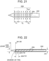
- FIG. 22 illustrates an elongate body 2302 of the type described in prior publications and denoted as the "original" or “O” configuration in the data described below.
- the elongate body 2302 has an outer diameter of about 0.51 mm, an inner diameter of about 0.41 mm, and includes 20 through-holes formed therein, which result in the creation of 40 total outlet ports 2304 that are each circular and have a diameter of about 0.15 mm (dimensions shown in the figure are in inches).
- a resulting ratio of total outlet port area to inner lumen area is about 6:1.
- the through-holes that form the outlet ports are placed at 60° intervals around the elongate body at a constant spacing of 0.6 mm for every 180° of revolution (i.e., every three holes such that this is the distance between adjacent axially-aligned outlet ports).
- the spray pattern into air for this elongate body is shown in FIG. 3 and demonstrates a lack of uniform emission. For example, there are no visible fluid jets from the proximal-most 4 or 5 rows of holes.
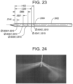
- FIG. 23 illustrates a first embodiment of an elongate body 2402 according to the teachings described herein.
- the elongate body 2402 includes 15 through-holes, resulting in 30 total circular outlet ports 2404 that vary in diameter from 0.076 mm distally to 0.11 mm proximally. A resulting ratio of total outlet port area to inner lumen area is about 1.7:1.
- the through-holes that form the outlet ports are placed at 60° intervals around the elongate body and the spacing between adjacent aligned holes varies according to the specification shown in FIG. 23 (again, dimensions shown are in inches).
- FIG. 24 depicts the spray of fluid (saline) into air for this elongate body at a flow rate of 35 ml/min.
- the spray pattern is clearly more uniform than that of the elongate body 2302 shown in FIG. 22 .
- the figure also shows some variation in angle, likely due to residual axial momentum of the exiting fluid.
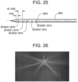
- FIG. 25 illustrates a second embodiment of an elongate body 2602 according to the teachings described herein.
- the elongate body 2602 includes 15 through-holes, resulting in 30 total circular outlet ports 2604 that vary in diameter from 0.061 mm distally to 0.091 mm proximally.
- a resulting ratio of total outlet port area to inner lumen area is about 1.07:1.
- the through-holes that form the outlet ports are placed at 60° intervals around the elongate body at a constant spacing of 0.81 mm per 180° revolution (i.e., the spacing between axially-aligned outlet ports along a longitudinal axis of the elongate body is 0.81 mm-dimensions shown in the figure are in inches).
- the elongate body 2602 depicts the spray of fluid into air for this elongate body at a flow rate of 35 ml/min.
- the pattern exhibits uniform flow with small variations of jet angle between rows of outlet ports.
- the elongate body 2602 is referred to as the "M2" configuration in the data described below.
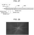
- FIG. 27 illustrates a third embodiment of an elongate body 2802 according to the teachings described herein.
- the elongate body 2802 includes 15 through-holes, resulting in 30 total circular outlet ports 2804 that vary in diameter from 0.048 mm distally to 0.081 mm proximally (dimensions shown in the figure are in inches).
- a resulting ratio of total outlet port area to inner lumen area is about 1.04:1.
- the through-holes that form the outlet ports are placed at 60° intervals around the elongate body at a constant spacing of 0.81 mm per 180° revolution.
- FIG. 28 depicts the spray of fluid into air for this elongate body at a flow rate of 35 ml/min. The pattern exhibits uniform flow with small variations of jet angle between rows of outlet ports.
- FIG. 30 shows a plot of lesion volume versus therapy power level for the original elongate body and selected embodiments of an elongate body according to the teachings of the present disclosure.
- utilizing an elongate body can create generally larger volumes of treated tissue when compared to elongate bodies known in the art.
- This can include, for example, an alternative pattern of outlet ports that vary in size and spacing, the inclusion of a flow diverter in an inner lumen of the elongate body, or a combination thereof.
- the inclusion of a flow diverter generally increased lesion volume, especially at higher power levels.
- Therapy impedance was also analyzed to determine which test ablations experienced a maximum therapy impedance below 100 ⁇ , between 100 and 150 ⁇ , and above 150 ⁇ . These categories were selected based on prior investigation and generally represent best-, moderate-, and worst-case impedance conditions for consistent power delivery. Qualitatively speaking, the results show that the elongate body configurations disclosed herein provide improved therapy performance by maintaining lower impedance levels.
- FIG. 32 and TABLE 3 below present selected results from the experimental ablation tests of the percentage of ablations performed with non-recovering impedance rises.
- the new elongate body configurations and/or the addition of a flow diverter feature perform better than the prior elongate body configuration.
- the "original" elongate body produced generally smaller lesions, by volume, than the elongate bodies constructed according to the teachings provided herein.
- the "M2" elongate body consistently produced larger lesions than the "original” embodiment at every power setting. Accordingly, qualitatively speaking, the "M2" elongate body outperformed the “original” elongate body.
- the addition of a flow diverter to the "M2" elongate body improved performance further.
- the "M2" and other alternative elongate bodies exhibited generally lower therapy impedance than the "original" elongate body, particularly as the therapy power was increased. This could be one explanation for the differences in therapy lesion volume produced by the "M2" elongate body, as the lower impedance can allow more consistent power delivery that is unaffected by current or voltage limits.
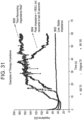
- FIG. 31 A significant performance improvement exhibited by the new elongate body embodiment is shown in FIG. 31 .
- the rate of unrecoverable impedance rises increases dramatically for the "original" elongate body, while the new embodiments experience far less of an increase.
- the rate of unrecoverable impedance remains below 20% for the "M2" and "O-FD" elongate bodies even at the highest power level.
- This decrease in runaway impedance is the result of better saline hydration of the surrounding tissue during therapy, which can be attributed to an improved flow pattern produced by the new elongate body hole pattern.
- the results of the experimental evaluation generally show improvements in therapy impedance and rate of non-recovering impedance rise. Any inconsistencies in the data may be attributable to the prototypes utilized, as tight tolerances are required for manufacture of these elongate bodies (e.g., to ensure that a flow diverter is centered within an inner lumen, etc.). Accordingly, data presented here should be considered more for its qualitative instruction regarding the performance comparison between an existing elongate body and the new embodiments described herein, and less for any quantitative comparison of the various embodiments.
- the results show that the elongate body configurations disclosed herein (i.e., embodiments employing alternative hole patterns and sizes, as well as the inclusion of a flow diverter feature) produce larger lesions or volumes of treated tissue and exhibit lower impedance than elongate bodies known in the art.
Landscapes
- Health & Medical Sciences (AREA)
- Surgery (AREA)
- Engineering & Computer Science (AREA)
- Life Sciences & Earth Sciences (AREA)
- Biomedical Technology (AREA)
- Molecular Biology (AREA)
- Nuclear Medicine, Radiotherapy & Molecular Imaging (AREA)
- Plasma & Fusion (AREA)
- Physics & Mathematics (AREA)
- Heart & Thoracic Surgery (AREA)
- Medical Informatics (AREA)
- Otolaryngology (AREA)
- Animal Behavior & Ethology (AREA)
- General Health & Medical Sciences (AREA)
- Public Health (AREA)
- Veterinary Medicine (AREA)
- Cardiology (AREA)
- Surgical Instruments (AREA)
Applications Claiming Priority (2)
| Application Number | Priority Date | Filing Date | Title |
|---|---|---|---|
| US15/234,858 US9743984B1 (en) | 2016-08-11 | 2016-08-11 | Devices and methods for delivering fluid to tissue during ablation therapy |
| PCT/US2017/044706 WO2018031281A1 (en) | 2016-08-11 | 2017-07-31 | Devices and methods for delivering fluid to tissue during ablation therapy |
Publications (4)
| Publication Number | Publication Date |
|---|---|
| EP3496641A1 EP3496641A1 (en) | 2019-06-19 |
| EP3496641A4 EP3496641A4 (en) | 2020-04-08 |
| EP3496641B1 true EP3496641B1 (en) | 2025-02-05 |
| EP3496641C0 EP3496641C0 (en) | 2025-02-05 |
Family
ID=59655301
Family Applications (1)
| Application Number | Title | Priority Date | Filing Date |
|---|---|---|---|
| EP17840018.0A Active EP3496641B1 (en) | 2016-08-11 | 2017-07-31 | Devices for delivering fluid to tissue during ablation therapy |
Country Status (7)
Families Citing this family (28)
| Publication number | Priority date | Publication date | Assignee | Title |
|---|---|---|---|---|
| BR112013026126A2 (pt) | 2011-04-12 | 2016-12-27 | Thermedical Inc | métodos e dispositivos para uso de fluidos desgaseificados com dispositivos de ablação otimizada por fluido |
| AU2012347470B2 (en) | 2011-12-09 | 2017-02-02 | Medtronic Ireland Manufacturing Unlimited Company | Therapeutic neuromodulation of the hepatic system |
| US10022176B2 (en) | 2012-08-15 | 2018-07-17 | Thermedical, Inc. | Low profile fluid enhanced ablation therapy devices and methods |
| US9033972B2 (en) | 2013-03-15 | 2015-05-19 | Thermedical, Inc. | Methods and devices for fluid enhanced microwave ablation therapy |
| WO2014197625A1 (en) | 2013-06-05 | 2014-12-11 | Metavention, Inc. | Modulation of targeted nerve fibers |
| US10643371B2 (en) * | 2014-08-11 | 2020-05-05 | Covidien Lp | Treatment procedure planning system and method |
| US10524859B2 (en) | 2016-06-07 | 2020-01-07 | Metavention, Inc. | Therapeutic tissue modulation devices and methods |
| AU2017301911B2 (en) | 2016-07-29 | 2022-07-28 | Axon Therapies, Inc. | Devices, systems, and methods for treatment of heart failure by splanchnic nerve ablation |
| US9743984B1 (en) | 2016-08-11 | 2017-08-29 | Thermedical, Inc. | Devices and methods for delivering fluid to tissue during ablation therapy |
| CN110267613B (zh) * | 2017-02-10 | 2023-07-21 | 圣犹达医疗用品心脏病学部门有限公司 | 用于冷冻消融的装置和方法 |
| US11020135B1 (en) * | 2017-04-25 | 2021-06-01 | Shockwave Medical, Inc. | Shock wave device for treating vascular plaques |
| CN109464186B (zh) | 2017-09-08 | 2023-12-22 | 泽丹医疗股份有限公司 | 治疗肺部肿瘤的装置和方法 |
| US10561461B2 (en) | 2017-12-17 | 2020-02-18 | Axon Therapies, Inc. | Methods and devices for endovascular ablation of a splanchnic nerve |
| WO2019148094A1 (en) | 2018-01-26 | 2019-08-01 | Axon Therapies, Inc. | Methods and devices for endovascular ablation of a splanchnic nerve |
| US11083871B2 (en) * | 2018-05-03 | 2021-08-10 | Thermedical, Inc. | Selectively deployable catheter ablation devices |
| US11918277B2 (en) | 2018-07-16 | 2024-03-05 | Thermedical, Inc. | Inferred maximum temperature monitoring for irrigated ablation therapy |
| WO2020185399A2 (en) * | 2019-03-08 | 2020-09-17 | Zidan Medical, Inc. | Systems, devices and methods for treating lung tumors |
| GB201904383D0 (en) * | 2019-03-29 | 2019-05-15 | Emblation Ltd | Microwave apparatus and method |
| US20200376249A1 (en) * | 2019-05-29 | 2020-12-03 | Penumbra, Inc. | Flushing catheter |
| AU2020296866A1 (en) | 2019-06-20 | 2021-10-14 | Axon Therapies, Inc. | Methods and devices for endovascular ablation of a splanchnic nerve |
| KR102286039B1 (ko) * | 2019-10-24 | 2021-08-05 | 주식회사 스타메드 | 천공용 의료 장치 |
| CN112648604B (zh) * | 2019-12-31 | 2025-06-27 | 杭州堃博生物科技有限公司 | 蒸汽消融设备 |
| ES2960299T3 (es) * | 2020-01-17 | 2024-03-04 | Axon Therapies Inc | Dispositivos para la ablación endovascular de un nervio esplácnico |
| CN111973267B (zh) * | 2020-09-27 | 2021-09-24 | 张海民 | 一种能够控制注射计量的微波消融针 |
| KR102741135B1 (ko) * | 2021-12-02 | 2024-12-11 | 주식회사 스타메드 | 천공용 의료 장치 |
| CN114288007B (zh) * | 2021-12-31 | 2022-09-30 | 心诺普医疗技术(北京)有限公司 | 流体喷射装置及冷冻球囊导管 |
| CN116370024A (zh) * | 2023-02-10 | 2023-07-04 | 上海汉通医疗科技有限公司 | 具有叠层结构的换能器 |
| EP4606358A1 (en) * | 2024-02-23 | 2025-08-27 | Schelin Medicin AB | Liquid injection device |
Family Cites Families (273)
| Publication number | Priority date | Publication date | Assignee | Title |
|---|---|---|---|---|
| GB1582135A (en) | 1976-07-14 | 1980-12-31 | Ferranti Ltd | Heaters |
| US4424190A (en) | 1982-02-22 | 1984-01-03 | Cordis Dow Corp. | Rigid shell expansible blood reservoir, heater and hollow fiber membrane oxygenator assembly |
| JPS62211056A (ja) | 1986-03-12 | 1987-09-17 | オリンパス光学工業株式会社 | 組織切除装置 |
| JPH01146539A (ja) | 1987-12-03 | 1989-06-08 | Olympus Optical Co Ltd | 超音波治療装置 |
| US5549559A (en) | 1990-03-22 | 1996-08-27 | Argomed Ltd. | Thermal treatment apparatus |
| DE9190129U1 (de) | 1990-09-14 | 1993-07-01 | American Medical Systems, Inc., Minnetonka, Minn. | Kombinierter Hyperthermie- und Dilatations-Katheter |
| US5190538A (en) | 1991-04-22 | 1993-03-02 | Trimedyne, Inc. | Method and apparatus for subjecting a body site to a movable beam of laterally directed laser radiation |
| EP0566725B1 (en) | 1991-11-08 | 2003-06-04 | Boston Scientific Limited | Ablation electrode with insulated temperature sensing elements |
| IT1251997B (it) | 1991-11-11 | 1995-05-27 | San Romanello Centro Fond | Dispositivo radiante per ipertermia |
| US6277112B1 (en) | 1996-07-16 | 2001-08-21 | Arthrocare Corporation | Methods for electrosurgical spine surgery |
| JP3774477B2 (ja) | 1992-02-10 | 2006-05-17 | アロカ株式会社 | 手術装置 |
| US5333603A (en) | 1992-02-25 | 1994-08-02 | Daniel Schuman | Endoscope with palm rest |
| US5271413A (en) | 1992-07-22 | 1993-12-21 | Dalamagas Photios P | Method to sense the tissue for injection from a hypodermic needle |
| WO1994010948A1 (en) | 1992-11-12 | 1994-05-26 | Neuwirth Robert S | Heated balloon medical apparatus |
| US5437673A (en) | 1993-02-04 | 1995-08-01 | Cryomedical Sciences, Inc. | Closed circulation tissue warming apparatus and method of using the same in prostate surgery |
| US6033383A (en) | 1996-12-19 | 2000-03-07 | Ginsburg; Robert | Temperature regulating catheter and methods |
| US5403311A (en) | 1993-03-29 | 1995-04-04 | Boston Scientific Corporation | Electro-coagulation and ablation and other electrotherapeutic treatments of body tissue |
| US5336222A (en) | 1993-03-29 | 1994-08-09 | Boston Scientific Corporation | Integrated catheter for diverse in situ tissue therapy |
| US5431649A (en) | 1993-08-27 | 1995-07-11 | Medtronic, Inc. | Method and apparatus for R-F ablation |
| US5449380A (en) | 1993-09-17 | 1995-09-12 | Origin Medsystems, Inc. | Apparatus and method for organ ablation |
| US5536267A (en) | 1993-11-08 | 1996-07-16 | Zomed International | Multiple electrode ablation apparatus |
| US5728143A (en) | 1995-08-15 | 1998-03-17 | Rita Medical Systems, Inc. | Multiple antenna ablation apparatus and method |
| US5458597A (en) | 1993-11-08 | 1995-10-17 | Zomed International | Device for treating cancer and non-malignant tumors and methods |
| US5472441A (en) | 1993-11-08 | 1995-12-05 | Zomed International | Device for treating cancer and non-malignant tumors and methods |
| US6071280A (en) | 1993-11-08 | 2000-06-06 | Rita Medical Systems, Inc. | Multiple electrode ablation apparatus |
| US6641580B1 (en) | 1993-11-08 | 2003-11-04 | Rita Medical Systems, Inc. | Infusion array ablation apparatus |
| US5462521A (en) | 1993-12-21 | 1995-10-31 | Angeion Corporation | Fluid cooled and perfused tip for a catheter |
| US5409487A (en) | 1994-01-28 | 1995-04-25 | Yab Revo-Tech Inc. | Auxiliary tubing probe |
| US5573510A (en) | 1994-02-28 | 1996-11-12 | Isaacson; Dennis R. | Safety intravenous catheter assembly with automatically retractable needle |
| US5437629A (en) | 1994-04-14 | 1995-08-01 | Bei Medical Systems | Fluid delivery system for hysteroscopic endometrial ablation |
| US20050187599A1 (en) | 1994-05-06 | 2005-08-25 | Hugh Sharkey | Method and apparatus for controlled contraction of soft tissue |
| US5843021A (en) | 1994-05-09 | 1998-12-01 | Somnus Medical Technologies, Inc. | Cell necrosis apparatus |
| US6024743A (en) | 1994-06-24 | 2000-02-15 | Edwards; Stuart D. | Method and apparatus for selective treatment of the uterus |
| US5735846A (en) | 1994-06-27 | 1998-04-07 | Ep Technologies, Inc. | Systems and methods for ablating body tissue using predicted maximum tissue temperature |
| US5545195A (en) | 1994-08-01 | 1996-08-13 | Boston Scientific Corporation | Interstitial heating of tissue |
| US5609151A (en) | 1994-09-08 | 1997-03-11 | Medtronic, Inc. | Method for R-F ablation |
| US6678552B2 (en) | 1994-10-24 | 2004-01-13 | Transscan Medical Ltd. | Tissue characterization based on impedance images and on impedance measurements |
| US6409722B1 (en) | 1998-07-07 | 2002-06-25 | Medtronic, Inc. | Apparatus and method for creating, maintaining, and controlling a virtual electrode used for the ablation of tissue |
| US6030379A (en) | 1995-05-01 | 2000-02-29 | Ep Technologies, Inc. | Systems and methods for seeking sub-surface temperature conditions during tissue ablation |
| US5697949A (en) | 1995-05-18 | 1997-12-16 | Symbiosis Corporation | Small diameter endoscopic instruments |
| SE505332C2 (sv) | 1995-05-18 | 1997-08-11 | Lund Instr Ab | Anordning för värmebehandling av kroppsvävnad |
| US6772012B2 (en) | 1995-06-07 | 2004-08-03 | Arthrocare Corporation | Methods for electrosurgical treatment of spinal tissue |
| WO2003024506A2 (en) | 2001-09-14 | 2003-03-27 | Arthrocare Corporation | Methods and apparatus for treating intervertebral discs |
| US20050004634A1 (en) | 1995-06-07 | 2005-01-06 | Arthrocare Corporation | Methods for electrosurgical treatment of spinal tissue |
| US7179255B2 (en) | 1995-06-07 | 2007-02-20 | Arthrocare Corporation | Methods for targeted electrosurgery on contained herniated discs |
| US6117131A (en) * | 1995-06-09 | 2000-09-12 | Engineering & Research Associates, Inc. | Multi-electrode probe for thermal ablation |
| ES2150676T5 (es) | 1995-06-23 | 2006-04-16 | Gyrus Medical Limited | Instrumento electroquirurgico. |
| US6689127B1 (en) | 1995-08-15 | 2004-02-10 | Rita Medical Systems | Multiple antenna ablation apparatus and method with multiple sensor feedback |
| US6235023B1 (en) | 1995-08-15 | 2001-05-22 | Rita Medical Systems, Inc. | Cell necrosis apparatus |
| US6669685B1 (en) | 1997-11-06 | 2003-12-30 | Biolase Technology, Inc. | Tissue remover and method |
| US5653692A (en) | 1995-09-07 | 1997-08-05 | Innerdyne Medical, Inc. | Method and system for direct heating of fluid solution in a hollow body organ |
| US5891094A (en) | 1995-09-07 | 1999-04-06 | Innerdyne, Inc. | System for direct heating of fluid solution in a hollow body organ and methods |
| US6283951B1 (en) | 1996-10-11 | 2001-09-04 | Transvascular, Inc. | Systems and methods for delivering drugs to selected locations within the body |
| US6090106A (en) | 1996-01-09 | 2000-07-18 | Gyrus Medical Limited | Electrosurgical instrument |
| US6475213B1 (en) | 1996-01-19 | 2002-11-05 | Ep Technologies, Inc. | Method of ablating body tissue |
| US5800482A (en) | 1996-03-06 | 1998-09-01 | Cardiac Pathways Corporation | Apparatus and method for linear lesion ablation |
| US6032077A (en) | 1996-03-06 | 2000-02-29 | Cardiac Pathways Corporation | Ablation catheter with electrical coupling via foam drenched with a conductive fluid |
| US6419673B1 (en) | 1996-05-06 | 2002-07-16 | Stuart Edwards | Ablation of rectal and other internal body structures |
| US6565561B1 (en) | 1996-06-20 | 2003-05-20 | Cyrus Medical Limited | Electrosurgical instrument |
| US5891134A (en) | 1996-09-24 | 1999-04-06 | Goble; Colin | System and method for applying thermal energy to tissue |
| US5954719A (en) | 1996-12-11 | 1999-09-21 | Irvine Biomedical, Inc. | System for operating a RF ablation generator |
| US5827269A (en) | 1996-12-31 | 1998-10-27 | Gynecare, Inc. | Heated balloon having a reciprocating fluid agitator |
| US5797848A (en) | 1997-01-31 | 1998-08-25 | Acuson Corporation | Ultrasonic transducer assembly with improved electrical interface |
| US6411852B1 (en) | 1997-04-07 | 2002-06-25 | Broncus Technologies, Inc. | Modification of airways by application of energy |
| US6272370B1 (en) | 1998-08-07 | 2001-08-07 | The Regents Of University Of Minnesota | MR-visible medical device for neurological interventions using nonlinear magnetic stereotaxis and a method imaging |
| US6139570A (en) | 1997-05-19 | 2000-10-31 | Gynelab Products, Inc. | Disposable bladder for intrauterine use |
| US6997925B2 (en) | 1997-07-08 | 2006-02-14 | Atrionx, Inc. | Tissue ablation device assembly and method for electrically isolating a pulmonary vein ostium from an atrial wall |
| US6139571A (en) | 1997-07-09 | 2000-10-31 | Fuller Research Corporation | Heated fluid surgical instrument |
| US6080151A (en) * | 1997-07-21 | 2000-06-27 | Daig Corporation | Ablation catheter |
| US6056747A (en) | 1997-08-04 | 2000-05-02 | Gynecare, Inc. | Apparatus and method for treatment of body tissues |
| US6045549A (en) | 1997-09-30 | 2000-04-04 | Somnus Medical Technologies, Inc. | Tissue ablation apparatus and device for use therein and method |
| US6176857B1 (en) | 1997-10-22 | 2001-01-23 | Oratec Interventions, Inc. | Method and apparatus for applying thermal energy to tissue asymmetrically |
| CA2308290A1 (en) | 1997-10-30 | 1999-05-14 | Sonique Surgical Systems, Inc. | Laser-assisted liposuction method and apparatus |
| JPH11178787A (ja) | 1997-12-18 | 1999-07-06 | Olympus Optical Co Ltd | 内視鏡システム |
| JP2001526098A (ja) | 1997-12-22 | 2001-12-18 | セルガード,インコーポレイティド | 液体中のガス泡と溶解されたガスとを除去する装置 |
| US7001378B2 (en) | 1998-03-31 | 2006-02-21 | Innercool Therapies, Inc. | Method and device for performing cooling or cryo-therapies, for, e.g., angioplasty with reduced restenosis or pulmonary vein cell necrosis to inhibit atrial fibrillation employing tissue protection |
| WO2004007013A1 (en) | 2002-06-20 | 2004-01-22 | Becton Dickinson And Company | Method and apparatus for shielding the tip of a catheter introducer needle |
| US6337994B1 (en) | 1998-04-30 | 2002-01-08 | Johns Hopkins University | Surgical needle probe for electrical impedance measurements |
| US6540725B1 (en) | 1998-06-04 | 2003-04-01 | Biosense Webster, Inc. | Injection catheter with controllably extendable injection needle |
| US6315777B1 (en) | 1998-07-07 | 2001-11-13 | Medtronic, Inc. | Method and apparatus for creating a virtual electrode used for the ablation of tissue |
| US6238393B1 (en) | 1998-07-07 | 2001-05-29 | Medtronic, Inc. | Method and apparatus for creating a bi-polar virtual electrode used for the ablation of tissue |
| US6494902B2 (en) | 1998-07-07 | 2002-12-17 | Medtronic, Inc. | Method for creating a virtual electrode for the ablation of tissue and for selected protection of tissue during an ablation |
| US6112123A (en) | 1998-07-28 | 2000-08-29 | Endonetics, Inc. | Device and method for ablation of tissue |
| US6450990B1 (en) | 1998-08-13 | 2002-09-17 | Alsius Corporation | Catheter with multiple heating/cooling fibers employing fiber spreading features |
| EP1104328A1 (en) | 1998-08-14 | 2001-06-06 | K.U. Leuven Research & Development | Expandable wet electrode |
| US6208881B1 (en) | 1998-10-20 | 2001-03-27 | Micropure Medical, Inc. | Catheter with thin film electrodes and method for making same |
| US6328735B1 (en) | 1998-10-30 | 2001-12-11 | E.P., Limited | Thermal ablation system |
| US6210406B1 (en) | 1998-12-03 | 2001-04-03 | Cordis Webster, Inc. | Split tip electrode catheter and signal processing RF ablation system |
| SE9804388D0 (sv) | 1998-12-17 | 1998-12-17 | Wallsten Medical Sa | Device and method for medical treatment |
| US6233490B1 (en) | 1999-02-09 | 2001-05-15 | Kai Technologies, Inc. | Microwave antennas for medical hyperthermia, thermotherapy and diagnosis |
| DE60035263T2 (de) | 1999-03-02 | 2008-02-21 | Atrionix Inc., Palo Alto | Atriale ablationsvorrichtung mit ballon und sensor |
| US6203507B1 (en) | 1999-03-03 | 2001-03-20 | Cordis Webster, Inc. | Deflectable catheter with ergonomic handle |
| US6358273B1 (en) | 1999-04-09 | 2002-03-19 | Oratec Inventions, Inc. | Soft tissue heating apparatus with independent, cooperative heating sources |
| EP1200213B1 (de) | 1999-07-29 | 2003-03-05 | Hatebur Umformmaschinen AG | Vorrichtung zur erzeugung einer hebe- und senkbewegung |
| US7815590B2 (en) | 1999-08-05 | 2010-10-19 | Broncus Technologies, Inc. | Devices for maintaining patency of surgically created channels in tissue |
| US6463332B1 (en) | 1999-09-17 | 2002-10-08 | Core Medical, Inc. | Method and system for pericardial enhancement |
| WO2001026570A1 (en) | 1999-10-13 | 2001-04-19 | Arthrocare Corporation | Systems and methods for treating spinal pain |
| US6529756B1 (en) | 1999-11-22 | 2003-03-04 | Scimed Life Systems, Inc. | Apparatus for mapping and coagulating soft tissue in or around body orifices |
| US6443947B1 (en) | 2000-03-01 | 2002-09-03 | Alexei Marko | Device for thermal ablation of a cavity |
| US20040220559A1 (en) | 2000-03-01 | 2004-11-04 | Kramer Hans W. | Preparation of working fluid for use in cryotherapies |
| ATE397900T1 (de) | 2000-03-06 | 2008-07-15 | Salient Surgical Technologies | Flüssigkeitsabgabesystem und steuerung für elektrochirurgische geräte |
| AU5113401A (en) | 2000-03-31 | 2001-10-15 | Rita Medical Systems Inc | Tissue biopsy and treatment apparatus and method |
| FR2807827B1 (fr) | 2000-04-12 | 2002-07-05 | Technomed Medical Systems | Systeme de manipulation de fluide pour appareil de therapie |
| US6514250B1 (en) * | 2000-04-27 | 2003-02-04 | Medtronic, Inc. | Suction stabilized epicardial ablation devices |
| US20020107514A1 (en) | 2000-04-27 | 2002-08-08 | Hooven Michael D. | Transmural ablation device with parallel jaws |
| US6558382B2 (en) | 2000-04-27 | 2003-05-06 | Medtronic, Inc. | Suction stabilized epicardial ablation devices |
| US6511478B1 (en) | 2000-06-30 | 2003-01-28 | Scimed Life Systems, Inc. | Medical probe with reduced number of temperature sensor wires |
| US6477396B1 (en) | 2000-07-07 | 2002-11-05 | Biosense Webster, Inc. | Mapping and ablation catheter |
| US6405067B1 (en) | 2000-07-07 | 2002-06-11 | Biosense Webster, Inc. | Catheter with tip electrode having a recessed ring electrode mounted thereon |
| WO2002005720A1 (en) | 2000-07-13 | 2002-01-24 | Transurgical, Inc. | Energy application with inflatable annular lens |
| EP1304971A1 (en) | 2000-07-25 | 2003-05-02 | Rita Medical Systems, Inc. | Apparatus for detecting and treating tumors using localized impedance measurement |
| US6855154B2 (en) | 2000-08-11 | 2005-02-15 | University Of Louisville Research Foundation, Inc. | Endovascular aneurysm treatment device and method |
| CN1246052C (zh) | 2000-09-06 | 2006-03-22 | 辅助呼吸产品公司 | 静脉输液的加热系统 |
| US6564096B2 (en) | 2001-02-28 | 2003-05-13 | Robert A. Mest | Method and system for treatment of tachycardia and fibrillation |
| US6666862B2 (en) | 2001-03-01 | 2003-12-23 | Cardiac Pacemakers, Inc. | Radio frequency ablation system and method linking energy delivery with fluid flow |
| US6418968B1 (en) * | 2001-04-20 | 2002-07-16 | Nanostream, Inc. | Porous microfluidic valves |
| US7160296B2 (en) | 2001-05-10 | 2007-01-09 | Rita Medical Systems, Inc. | Tissue ablation apparatus and method |
| US6752802B1 (en) | 2001-07-09 | 2004-06-22 | Ethicon, Inc. | Method and apparatus for the prevention of endometrial hyperplasis and uterine cancer |
| AU2002326548A1 (en) | 2001-08-17 | 2003-04-14 | Innercool Therapies, Inc. | Preparation of working fluid for use in cryotherapies |
| AU2002336575A1 (en) | 2001-09-14 | 2003-04-01 | Arthrocare Corporation | Electrosurgical apparatus and methods for tissue treatment and removal |
| GB2379878B (en) | 2001-09-21 | 2004-11-10 | Gyrus Medical Ltd | Electrosurgical system and method |
| US6814730B2 (en) | 2001-10-09 | 2004-11-09 | Hong Li | Balloon catheters for non-continuous lesions |
| US7070597B2 (en) | 2001-10-18 | 2006-07-04 | Surgrx, Inc. | Electrosurgical working end for controlled energy delivery |
| US6603997B2 (en) | 2001-11-02 | 2003-08-05 | Michael C. Doody | Probe penetration detector and method of operation |
| US20050267552A1 (en) | 2004-05-26 | 2005-12-01 | Baylis Medical Company Inc. | Electrosurgical device |
| CN1856269A (zh) | 2002-04-22 | 2006-11-01 | 马尔西奥·马克·阿布雷乌 | 用于测量生物学参数的装置和方法 |
| JP4394864B2 (ja) * | 2002-05-07 | 2010-01-06 | テルモ株式会社 | 金属製の管状体およびその製造方法 |
| US7294143B2 (en) | 2002-05-16 | 2007-11-13 | Medtronic, Inc. | Device and method for ablation of cardiac tissue |
| IL149706A0 (en) | 2002-05-16 | 2002-11-10 | Dolopaz Technologies Ltd | Multipurpose fluid jet surgical device |
| JP2004024331A (ja) | 2002-06-21 | 2004-01-29 | Vayu:Kk | カテーテル |
| US20040006336A1 (en) | 2002-07-02 | 2004-01-08 | Scimed Life Systems, Inc. | Apparatus and method for RF ablation into conductive fluid-infused tissue |
| US20040116922A1 (en) | 2002-09-05 | 2004-06-17 | Arthrocare Corporation | Methods and apparatus for treating intervertebral discs |
| WO2004039273A2 (en) | 2002-10-31 | 2004-05-13 | C.R. Bard, Inc. | Electrophysiology catheter with biased tip |
| AU2002952663A0 (en) | 2002-11-14 | 2002-11-28 | Western Sydney Area Health Service | An intramural needle-tipped surgical device |
| WO2004050056A1 (en) * | 2002-11-29 | 2004-06-17 | Cochlear Limited | Cochlear implant drug delivery device |
| US6972014B2 (en) | 2003-01-04 | 2005-12-06 | Endocare, Inc. | Open system heat exchange catheters and methods of use |
| JP2004275594A (ja) | 2003-03-18 | 2004-10-07 | Terumo Corp | 注射針突出量調整機構を有するカテーテル |
| US7025768B2 (en) | 2003-05-06 | 2006-04-11 | Boston Scientific Scimed, Inc. | Systems and methods for ablation of tissue |
| US20060129091A1 (en) * | 2004-12-10 | 2006-06-15 | Possis Medical, Inc. | Enhanced cross stream mechanical thrombectomy catheter with backloading manifold |
| US7235070B2 (en) * | 2003-07-02 | 2007-06-26 | St. Jude Medical, Atrial Fibrillation Division, Inc. | Ablation fluid manifold for ablation catheter |
| US7311703B2 (en) | 2003-07-18 | 2007-12-25 | Vivant Medical, Inc. | Devices and methods for cooling microwave antennas |
| US7104989B2 (en) | 2003-09-05 | 2006-09-12 | Medtronic, Inc. | RF ablation catheter including a virtual electrode assembly |
| US20050059963A1 (en) | 2003-09-12 | 2005-03-17 | Scimed Life Systems, Inc. | Systems and method for creating transmural lesions |
| US20050080410A1 (en) | 2003-10-14 | 2005-04-14 | Scimed Life Systems, Inc. | Liquid infusion apparatus for radiofrequency tissue ablation |
| US7155270B2 (en) | 2003-10-24 | 2006-12-26 | Biosense Webster, Inc. | Catheter with multi-spine mapping assembly |
| US7179256B2 (en) | 2003-10-24 | 2007-02-20 | Biosense Webster, Inc. | Catheter with ablation needle and mapping assembly |
| US7207989B2 (en) | 2003-10-27 | 2007-04-24 | Biosense Webster, Inc. | Method for ablating with needle electrode |
| NL1024658C2 (nl) | 2003-10-29 | 2005-05-02 | Univ Medisch Centrum Utrecht | Katheter en werkwijze, in het bijzonder voor ablatie en dergelijke techniek. |
| US7282051B2 (en) | 2004-02-04 | 2007-10-16 | Boston Scientific Scimed, Inc. | Ablation probe for delivering fluid through porous structure |
| US20050192652A1 (en) | 2004-02-26 | 2005-09-01 | Iulian Cioanta | Thermal treatment systems with enhanced tissue penetration depth using adjustable treatment pressures and related methods |
| WO2005089663A1 (en) | 2004-03-05 | 2005-09-29 | Medelec-Minimeca S.A. | Saline-enhanced catheter for radiofrequency tumor ablation |
| CN1942145A (zh) | 2004-04-19 | 2007-04-04 | 普罗里森姆股份有限公司 | 带传感器结构的消融装置 |
| US7244254B2 (en) | 2004-04-29 | 2007-07-17 | Micrablate | Air-core microwave ablation antennas |
| US20050245923A1 (en) | 2004-04-29 | 2005-11-03 | Medtronic, Inc. | Biopolar virtual electrode for transurethral needle ablation |
| US7101369B2 (en) | 2004-04-29 | 2006-09-05 | Wisconsin Alumni Research Foundation | Triaxial antenna for microwave tissue ablation |
| US9061120B2 (en) | 2004-08-05 | 2015-06-23 | Oscor Inc. | Catheter control mechanism and steerable catheter |
| EP1796568A1 (en) | 2004-09-09 | 2007-06-20 | Vnus Medical Technologies, Inc. | Methods and apparatus for treatment of hollow anatomical structures |
| US7412273B2 (en) | 2004-11-15 | 2008-08-12 | Biosense Webster, Inc. | Soft linear mapping catheter with stabilizing tip |
| AU2005307758B2 (en) | 2004-11-15 | 2011-08-25 | Biosense Webster Inc. | Catheter with multiple microfabricated temperature sensors |
| US20060118127A1 (en) | 2004-12-06 | 2006-06-08 | Chinn Douglas O | Tissue protective system and method for thermoablative therapies |
| WO2006063318A1 (en) | 2004-12-09 | 2006-06-15 | Palomar Medical Technologies, Inc. | Oral appliance with heat transfer mechanism |
| US7666166B1 (en) | 2004-12-27 | 2010-02-23 | Blivic, Llc | Bloodless intravenous integrated catheter |
| KR100640283B1 (ko) | 2004-12-28 | 2006-11-01 | 최정숙 | 고주파 전기 수술용 전극 |
| GB0504988D0 (en) | 2005-03-10 | 2005-04-20 | Emcision Ltd | Device and method for the treatment of diseased tissue such as tumors |
| US8765116B2 (en) | 2005-03-24 | 2014-07-01 | Medifocus, Inc. | Apparatus and method for pre-conditioning/fixation and treatment of disease with heat activation/release with thermoactivated drugs and gene products |
| US7942873B2 (en) | 2005-03-25 | 2011-05-17 | Angiodynamics, Inc. | Cavity ablation apparatus and method |
| JPWO2006103951A1 (ja) | 2005-03-29 | 2008-09-04 | テルモ株式会社 | 脱気モジュール付医療用送液管と、該医療用送液管を用いる医療用機器アッセンブリ及び脱気モジュール並びに送液方法 |
| US7799019B2 (en) | 2005-05-10 | 2010-09-21 | Vivant Medical, Inc. | Reinforced high strength microwave antenna |
| US8128621B2 (en) | 2005-05-16 | 2012-03-06 | St. Jude Medical, Atrial Fibrillation Division, Inc. | Irrigated ablation electrode assembly and method for control of temperature |
| US8333776B2 (en) | 2005-05-20 | 2012-12-18 | Neotract, Inc. | Anchor delivery system |
| US7621890B2 (en) | 2005-06-09 | 2009-11-24 | Endocare, Inc. | Heat exchange catheter with multi-lumen tube having a fluid return passageway |
| US8123693B2 (en) | 2005-06-20 | 2012-02-28 | Conceptus, Inc. | Methods and devices for determining lumen occlusion |
| US7819868B2 (en) | 2005-06-21 | 2010-10-26 | St. Jude Medical, Atrial Fibrilation Division, Inc. | Ablation catheter with fluid distribution structures |
| US7879030B2 (en) | 2005-07-27 | 2011-02-01 | St. Jude Medical, Atrial Fibrillation Division, Inc. | Multipolar, virtual-electrode catheter with at least one surface electrode and method for ablation |
| US8353906B2 (en) | 2005-08-01 | 2013-01-15 | Ceramatec, Inc. | Electrochemical probe and method for in situ treatment of a tissue |
| US7766906B2 (en) * | 2005-08-19 | 2010-08-03 | Boston Scientific Scimed, Inc. | Occlusion apparatus |
| US7416552B2 (en) | 2005-08-22 | 2008-08-26 | St. Jude Medical, Atrial Fibrillation Division, Inc. | Multipolar, multi-lumen, virtual-electrode catheter with at least one surface electrode and method for ablation |
| US20070078453A1 (en) | 2005-10-04 | 2007-04-05 | Johnson Kristin D | System and method for performing cardiac ablation |
| US8182444B2 (en) | 2005-11-04 | 2012-05-22 | Medrad, Inc. | Delivery of agents such as cells to tissue |
| US8449535B2 (en) | 2005-12-06 | 2013-05-28 | St. Jude Medical, Atrial Fibrillation Division, Inc. | System and method for assessing coupling between an electrode and tissue |
| US9283025B2 (en) | 2005-12-06 | 2016-03-15 | St. Jude Medical, Atrial Fibrillation Division, Inc. | Assessment of electrode coupling for tissue ablation |
| US20100168567A1 (en) | 2005-12-15 | 2010-07-01 | Galil Medical Ltd. | Apparatus for Protecting a Cavity Wall During Ablation of Tissue Near the Cavity |
| WO2007080578A2 (en) | 2006-01-09 | 2007-07-19 | Biospiral Ltd. | System and method for thermally treating tissues |
| CN2885157Y (zh) | 2006-03-23 | 2007-04-04 | 迈德医疗科技(上海)有限公司 | 可灌注式探针电极 |
| US9814519B2 (en) | 2006-04-20 | 2017-11-14 | Boston Scientific Scimed, Inc. | Ablation probe with ribbed insulated sheath |
| WO2007140278A2 (en) | 2006-05-24 | 2007-12-06 | Rush University Medical Center | High temperature thermal therapy of breast cancer |
| US8114071B2 (en) | 2006-05-30 | 2012-02-14 | Arthrocare Corporation | Hard tissue ablation system |
| US7662152B2 (en) | 2006-06-13 | 2010-02-16 | Biosense Webster, Inc. | Catheter with multi port tip for optical lesion evaluation |
| US7559905B2 (en) | 2006-09-21 | 2009-07-14 | Focus Surgery, Inc. | HIFU probe for treating tissue with in-line degassing of fluid |
| EP2066251B1 (en) * | 2006-10-10 | 2017-05-03 | St. Jude Medical, Atrial Fibrillation Division, Inc. | Ablation electrode assembly with insulated distal outlet |
| US8728073B2 (en) | 2006-10-10 | 2014-05-20 | Biosense Webster, Inc. | Multi-region staged inflation balloon |
| WO2008045877A2 (en) | 2006-10-10 | 2008-04-17 | St. Jude Medical, Atrial Fibrillation Division, Inc. | Electrode tip and ablation system |
| US20080091181A1 (en) * | 2006-10-11 | 2008-04-17 | Shlomo Gabbay | System and method for ablation |
| CN100574719C (zh) | 2006-12-26 | 2009-12-30 | 上海导向医疗系统有限公司 | 气体节流冷却式射频消融电极 |
| US7951143B2 (en) | 2006-12-28 | 2011-05-31 | St. Jude Medical, Artial Fibrillation Divsion, Inc. | Cooled ablation catheter with reciprocating flow |
| US7766907B2 (en) * | 2006-12-28 | 2010-08-03 | St. Jude Medical, Atrial Fibrillation Division, Inc. | Ablation catheter with sensor array and discrimination circuit to minimize variation in power density |
| US8460285B2 (en) | 2006-12-29 | 2013-06-11 | St. Jude Medical, Atrial Fibrillation Division, Inc. | Ablation catheter electrode having multiple thermal sensors and method of use |
| US8764742B2 (en) * | 2007-04-04 | 2014-07-01 | St. Jude Medical, Atrial Fibrillation Division, Inc. | Irrigated catheter |
| US9314298B2 (en) | 2007-04-17 | 2016-04-19 | St. Jude Medical, Atrial Fibrillation Divisions, Inc. | Vacuum-stabilized ablation system |
| US8579886B2 (en) | 2007-05-01 | 2013-11-12 | Covidien Lp | Accordion style cable stand-off |
| US20080275440A1 (en) | 2007-05-03 | 2008-11-06 | Medtronic, Inc. | Post-ablation verification of lesion size |
| US20080281200A1 (en) | 2007-05-10 | 2008-11-13 | Misonix, Incorporated | Elevated coupling liquid temperature during HIFU treatment method and hardware |
| EP2178585B1 (en) * | 2007-08-14 | 2021-04-07 | Fred Hutchinson Cancer Research Center | Needle array assembly and method for delivering therapeutic agents |
| US20090082837A1 (en) | 2007-09-20 | 2009-03-26 | Gellman Barry N | Hand-held Thermal Ablation Device |
| US20090088785A1 (en) | 2007-09-28 | 2009-04-02 | Shinya Masuda | Surgical operating apparatus |
| US9023030B2 (en) * | 2007-10-09 | 2015-05-05 | Boston Scientific Scimed, Inc. | Cooled ablation catheter devices and methods of use |
| CN101411645A (zh) | 2007-10-19 | 2009-04-22 | 上海导向医疗系统有限公司 | 表面温度均匀的射频消融电极 |
| US8535306B2 (en) | 2007-11-05 | 2013-09-17 | Angiodynamics, Inc. | Ablation devices and methods of using the same |
| US8439907B2 (en) | 2007-11-07 | 2013-05-14 | Mirabilis Medica Inc. | Hemostatic tissue tunnel generator for inserting treatment apparatus into tissue of a patient |
| US8128620B2 (en) | 2007-11-13 | 2012-03-06 | St. Jude Medical, Atrial Fibrillation Division, Inc. | Irrigated ablation electrode having proximal direction flow |
| US20090125014A1 (en) | 2007-11-14 | 2009-05-14 | Bouthillier Robert J | Thermal Ablation System |
| US8444579B2 (en) | 2007-12-21 | 2013-05-21 | St. Jude Medical, Atrial Fibrillation Division, Inc. | System for delivering acoustic energy in connection with therapeutic ultrasound systems and catheters |
| US8273082B2 (en) | 2007-12-21 | 2012-09-25 | St. Jude Medical, Atrial Fibrillation Division, Inc. | Irrigated ablation catheter assembly having a flow member to create parallel external flow |
| US8333762B2 (en) | 2007-12-28 | 2012-12-18 | Biosense Webster, Inc. | Irrigated catheter with improved irrigation flow |
| EP2231002A1 (en) | 2008-01-09 | 2010-09-29 | Mayo Foundation for Medical Education and Research | Mapping and ablation catheter system |
| WO2009094604A1 (en) | 2008-01-25 | 2009-07-30 | Anacapa Arch Associates | Method and device for less invasive surgical procedures on animals |
| US20090254083A1 (en) | 2008-03-10 | 2009-10-08 | Hansen Medical, Inc. | Robotic ablation catheter |
| US9155476B2 (en) | 2008-03-18 | 2015-10-13 | Circa Scientific, Llc | Large surface area temperature sensing device |
| US20100004595A1 (en) | 2008-07-01 | 2010-01-07 | Ethicon, Inc. | Balloon catheter systems for treating uterine disorders having fluid line de-gassing assemblies and methods therefor |
| JP2010046200A (ja) | 2008-08-20 | 2010-03-04 | Fujinon Corp | 高周波処置具 |
| WO2010039894A1 (en) | 2008-09-30 | 2010-04-08 | Dfine, Inc. | System for use in treatment of vertebral fractures |
| US8758349B2 (en) | 2008-10-13 | 2014-06-24 | Dfine, Inc. | Systems for treating a vertebral body |
| US8512328B2 (en) | 2008-10-13 | 2013-08-20 | Covidien Lp | Antenna assemblies for medical applications |
| US9757189B2 (en) | 2008-12-03 | 2017-09-12 | Biosense Webster, Inc. | Prevention of kinks in catheter irrigation tubes |
| WO2010085457A1 (en) | 2009-01-20 | 2010-07-29 | Guided Delivery Systems Inc. | Diagnostic catheters, guide catheters, visualization devices and chord manipulation devices, and related kits and methods |
| WO2010151619A2 (en) | 2009-06-24 | 2010-12-29 | Optogen Medical Llc | Devices, systems and methods for treatment of soft tissue |
| CN201642316U (zh) | 2009-11-18 | 2010-11-24 | 南京康友微波能应用研究所 | 微波消融针及其微波消融治疗仪 |
| US20110160726A1 (en) | 2009-12-30 | 2011-06-30 | Frank Ingle | Apparatus and methods for fluid cooled electrophysiology procedures |
| US8764744B2 (en) | 2010-01-25 | 2014-07-01 | Covidien Lp | System for monitoring ablation size |
| US10058336B2 (en) | 2010-04-08 | 2018-08-28 | Dfine, Inc. | System for use in treatment of vertebral fractures |
| US9943363B2 (en) * | 2010-04-28 | 2018-04-17 | Biosense Webster, Inc. | Irrigated ablation catheter with improved fluid flow |
| US9943362B2 (en) | 2010-04-28 | 2018-04-17 | Biosense Webster, Inc. | Irrigated ablation catheter with improved fluid flow |
| US9510894B2 (en) * | 2010-04-28 | 2016-12-06 | Biosense Webster (Israel) Ltd. | Irrigated ablation catheter having irrigation ports with reduced hydraulic resistance |
| CN106618669B (zh) | 2010-04-29 | 2019-11-12 | Dfine有限公司 | 用于治疗椎骨骨折的系统 |
| US8696659B2 (en) | 2010-04-30 | 2014-04-15 | Arthrocare Corporation | Electrosurgical system and method having enhanced temperature measurement |
| WO2011141800A1 (en) | 2010-05-10 | 2011-11-17 | Endosense S.A. | Irrigated finned ablation head |
| US7938822B1 (en) | 2010-05-12 | 2011-05-10 | Icecure Medical Ltd. | Heating and cooling of cryosurgical instrument using a single cryogen |
| CA2818876C (en) | 2010-11-22 | 2018-10-02 | Dfine, Inc. | System for use in treatment of vertebral fractures |
| WO2012071058A1 (en) | 2010-11-23 | 2012-05-31 | William Joseph Drasler | Venous heated ablation catheter |
| CN101999931B (zh) | 2010-12-10 | 2012-11-14 | 上海导向医疗系统有限公司 | 一种覆盖可膨胀水凝胶的冷热消融探针壳体及其制备方法 |
| US9855094B2 (en) | 2010-12-28 | 2018-01-02 | St. Jude Medical, Atrial Fibrillation Division, Inc. | Multi-rate fluid flow and variable power delivery for ablation electrode assemblies used in catheter ablation procedures |
| CN108392263A (zh) | 2011-01-19 | 2018-08-14 | 弗拉克泰尔实验室公司 | 用于组织处理的装置与方法 |
| US20120253188A1 (en) | 2011-03-29 | 2012-10-04 | University Of Rochester | Reducing risk of complications associated with tissue ablation |
| BR112013026126A2 (pt) | 2011-04-12 | 2016-12-27 | Thermedical Inc | métodos e dispositivos para uso de fluidos desgaseificados com dispositivos de ablação otimizada por fluido |
| US20120310230A1 (en) | 2011-06-01 | 2012-12-06 | Angiodynamics, Inc. | Coaxial dual function probe and method of use |
| US9314588B2 (en) * | 2011-10-28 | 2016-04-19 | Medtronic Cryocath Lp | Systems and methods for variable injection flow |
| CN109938826A (zh) | 2012-03-27 | 2019-06-28 | Dfine有限公司 | 用于通过温度监视来控制组织切除体积的方法和系统 |
| WO2013159066A1 (en) | 2012-04-19 | 2013-10-24 | Fractyl Laboratories, Inc. | Tissue expansion devices, system and methods |
| US8700133B2 (en) | 2012-06-18 | 2014-04-15 | Smart Iv Llc | Apparatus and method for monitoring catheter insertion |
| US10022176B2 (en) * | 2012-08-15 | 2018-07-17 | Thermedical, Inc. | Low profile fluid enhanced ablation therapy devices and methods |
| DE102012220658A1 (de) * | 2012-11-13 | 2014-05-15 | Olympus Winter & Ibe Gmbh | Elektrochirurgisches Instrument für die Koagulation oder Ablation von Körpergewebe |
| WO2014089373A1 (en) | 2012-12-05 | 2014-06-12 | University Of Rochester | Catheter with integrated transeptal puncture needle |
| US9033972B2 (en) | 2013-03-15 | 2015-05-19 | Thermedical, Inc. | Methods and devices for fluid enhanced microwave ablation therapy |
| US9610396B2 (en) | 2013-03-15 | 2017-04-04 | Thermedical, Inc. | Systems and methods for visualizing fluid enhanced ablation therapy |
| CN105050523B (zh) * | 2013-03-15 | 2017-11-10 | 波士顿科学医学有限公司 | 开放式灌注消融导管 |
| US10682175B2 (en) | 2013-11-06 | 2020-06-16 | Biosense Webster (Israel) Ltd. | Using catheter position and temperature measurement to detect movement from ablation point |
| CA2945645C (en) | 2014-03-24 | 2021-10-26 | Old Dominion University Research Foundation | Expandable catheter devices electrode array |
| US9848943B2 (en) | 2014-04-18 | 2017-12-26 | Biosense Webster (Israel) Ltd. | Ablation catheter with dedicated fluid paths and needle centering insert |
| SG11201703943VA (en) | 2014-11-19 | 2017-06-29 | Advanced Cardiac Therapeutics Inc | Ablation devices, systems and methods of using a high-resolution electrode assembly |
| US10463425B2 (en) | 2015-05-04 | 2019-11-05 | Biosense Webster (Israel) Ltd. | RF ablation with acoustic feedback |
| US9844664B2 (en) | 2015-10-12 | 2017-12-19 | Medtronic, Inc. | Interventional medical systems, catheters, and subassemblies |
| WO2017091335A1 (en) | 2015-11-25 | 2017-06-01 | Smith And Nephew, Inc. | System and methods of controlling temperature related to electrosurgical procedures |
| CN105769332B (zh) * | 2016-02-22 | 2019-07-16 | 绵阳立德电子股份有限公司 | 射频能量分配控制器、rfa系统以及利用该控制器实现射频能量分配控制的方法 |
| US9743984B1 (en) | 2016-08-11 | 2017-08-29 | Thermedical, Inc. | Devices and methods for delivering fluid to tissue during ablation therapy |
| WO2019148094A1 (en) | 2018-01-26 | 2019-08-01 | Axon Therapies, Inc. | Methods and devices for endovascular ablation of a splanchnic nerve |
| US11083871B2 (en) | 2018-05-03 | 2021-08-10 | Thermedical, Inc. | Selectively deployable catheter ablation devices |
| JP2019211057A (ja) | 2018-06-08 | 2019-12-12 | Ntn株式会社 | アーマチュアの緩衝構造、回転伝達装置、および回転制動装置 |
| US11918277B2 (en) | 2018-07-16 | 2024-03-05 | Thermedical, Inc. | Inferred maximum temperature monitoring for irrigated ablation therapy |
| US20200376249A1 (en) | 2019-05-29 | 2020-12-03 | Penumbra, Inc. | Flushing catheter |
| AU2020296866A1 (en) | 2019-06-20 | 2021-10-14 | Axon Therapies, Inc. | Methods and devices for endovascular ablation of a splanchnic nerve |
| ES2960299T3 (es) | 2020-01-17 | 2024-03-04 | Axon Therapies Inc | Dispositivos para la ablación endovascular de un nervio esplácnico |
| CN111973267B (zh) | 2020-09-27 | 2021-09-24 | 张海民 | 一种能够控制注射计量的微波消融针 |
| KR102741135B1 (ko) | 2021-12-02 | 2024-12-11 | 주식회사 스타메드 | 천공용 의료 장치 |
-
2016
- 2016-08-11 US US15/234,858 patent/US9743984B1/en active Active
-
2017
- 2017-07-31 ES ES17840018T patent/ES3012847T3/es active Active
- 2017-07-31 JP JP2019507789A patent/JP2019524325A/ja active Pending
- 2017-07-31 CN CN202311491692.XA patent/CN117752409A/zh active Pending
- 2017-07-31 KR KR1020197005130A patent/KR102612869B1/ko active Active
- 2017-07-31 US US15/663,929 patent/US11013555B2/en active Active
- 2017-07-31 CN CN201780062751.8A patent/CN110461263B/zh active Active
- 2017-07-31 EP EP17840018.0A patent/EP3496641B1/en active Active
- 2017-07-31 KR KR1020237042367A patent/KR20230170148A/ko not_active Ceased
- 2017-07-31 WO PCT/US2017/044706 patent/WO2018031281A1/en unknown
-
2021
- 2021-04-29 US US17/244,145 patent/US12310651B2/en active Active
-
2022
- 2022-11-17 JP JP2022184097A patent/JP2023018017A/ja active Pending
Also Published As
| Publication number | Publication date |
|---|---|
| JP2019524325A (ja) | 2019-09-05 |
| EP3496641A1 (en) | 2019-06-19 |
| KR20230170148A (ko) | 2023-12-18 |
| WO2018031281A1 (en) | 2018-02-15 |
| KR20190041472A (ko) | 2019-04-22 |
| US12310651B2 (en) | 2025-05-27 |
| CN117752409A (zh) | 2024-03-26 |
| CN110461263A (zh) | 2019-11-15 |
| JP2023018017A (ja) | 2023-02-07 |
| EP3496641C0 (en) | 2025-02-05 |
| US11013555B2 (en) | 2021-05-25 |
| ES3012847T3 (en) | 2025-04-10 |
| US20210393322A1 (en) | 2021-12-23 |
| EP3496641A4 (en) | 2020-04-08 |
| US20180042669A1 (en) | 2018-02-15 |
| CN110461263B (zh) | 2023-11-28 |
| US9743984B1 (en) | 2017-08-29 |
| KR102612869B1 (ko) | 2023-12-11 |
Similar Documents
| Publication | Publication Date | Title |
|---|---|---|
| US12310651B2 (en) | Devices and methods for delivering fluid to tissue during ablation therapy | |
| AU2017200549B2 (en) | Methods and devices for heating fluid enhanced ablation therapy | |
| US7160296B2 (en) | Tissue ablation apparatus and method | |
| EP2884928B1 (en) | Ablation device with means for heating a fluid, with an electrode and with a handle provided at an angle | |
| JP7730527B2 (ja) | 灌流式切除療法の推定最大温度監視 | |
| CN112512450B (zh) | 双极冲洗射频消融尖齿探针 |
Legal Events
| Date | Code | Title | Description |
|---|---|---|---|
| STAA | Information on the status of an ep patent application or granted ep patent |
Free format text: STATUS: THE INTERNATIONAL PUBLICATION HAS BEEN MADE |
|
| PUAI | Public reference made under article 153(3) epc to a published international application that has entered the european phase |
Free format text: ORIGINAL CODE: 0009012 |
|
| STAA | Information on the status of an ep patent application or granted ep patent |
Free format text: STATUS: REQUEST FOR EXAMINATION WAS MADE |
|
| 17P | Request for examination filed |
Effective date: 20190228 |
|
| AK | Designated contracting states |
Kind code of ref document: A1 Designated state(s): AL AT BE BG CH CY CZ DE DK EE ES FI FR GB GR HR HU IE IS IT LI LT LU LV MC MK MT NL NO PL PT RO RS SE SI SK SM TR |
|
| AX | Request for extension of the european patent |
Extension state: BA ME |
|
| DAV | Request for validation of the european patent (deleted) | ||
| DAX | Request for extension of the european patent (deleted) | ||
| A4 | Supplementary search report drawn up and despatched |
Effective date: 20200305 |
|
| RIC1 | Information provided on ipc code assigned before grant |
Ipc: A61B 18/18 20060101AFI20200228BHEP Ipc: A61B 18/00 20060101ALI20200228BHEP Ipc: A61B 18/14 20060101ALI20200228BHEP Ipc: A61B 18/04 20060101ALI20200228BHEP |
|
| RIC1 | Information provided on ipc code assigned before grant |
Ipc: A61B 18/00 20060101ALI20240627BHEP Ipc: A61B 18/04 20060101ALI20240627BHEP Ipc: A61B 18/14 20060101ALI20240627BHEP Ipc: A61B 18/18 20060101AFI20240627BHEP |
|
| GRAP | Despatch of communication of intention to grant a patent |
Free format text: ORIGINAL CODE: EPIDOSNIGR1 |
|
| STAA | Information on the status of an ep patent application or granted ep patent |
Free format text: STATUS: GRANT OF PATENT IS INTENDED |
|
| INTG | Intention to grant announced |
Effective date: 20240812 |
|
| GRAS | Grant fee paid |
Free format text: ORIGINAL CODE: EPIDOSNIGR3 |
|
| GRAA | (expected) grant |
Free format text: ORIGINAL CODE: 0009210 |
|
| STAA | Information on the status of an ep patent application or granted ep patent |
Free format text: STATUS: THE PATENT HAS BEEN GRANTED |
|
| AK | Designated contracting states |
Kind code of ref document: B1 Designated state(s): AL AT BE BG CH CY CZ DE DK EE ES FI FR GB GR HR HU IE IS IT LI LT LU LV MC MK MT NL NO PL PT RO RS SE SI SK SM TR |
|
| REG | Reference to a national code |
Ref country code: GB Ref legal event code: FG4D |
|
| REG | Reference to a national code |
Ref country code: CH Ref legal event code: EP |
|
| REG | Reference to a national code |
Ref country code: DE Ref legal event code: R096 Ref document number: 602017087653 Country of ref document: DE |
|
| REG | Reference to a national code |
Ref country code: IE Ref legal event code: FG4D |
|
| U01 | Request for unitary effect filed |
Effective date: 20250228 |
|
| U07 | Unitary effect registered |
Designated state(s): AT BE BG DE DK EE FI FR IT LT LU LV MT NL PT RO SE SI Effective date: 20250310 |
|
| REG | Reference to a national code |
Ref country code: ES Ref legal event code: FG2A Ref document number: 3012847 Country of ref document: ES Kind code of ref document: T3 Effective date: 20250410 |
|
| PG25 | Lapsed in a contracting state [announced via postgrant information from national office to epo] |
Ref country code: RS Free format text: LAPSE BECAUSE OF FAILURE TO SUBMIT A TRANSLATION OF THE DESCRIPTION OR TO PAY THE FEE WITHIN THE PRESCRIBED TIME-LIMIT Effective date: 20250505 |
|
| PG25 | Lapsed in a contracting state [announced via postgrant information from national office to epo] |
Ref country code: PL Free format text: LAPSE BECAUSE OF FAILURE TO SUBMIT A TRANSLATION OF THE DESCRIPTION OR TO PAY THE FEE WITHIN THE PRESCRIBED TIME-LIMIT Effective date: 20250205 |
|
| PG25 | Lapsed in a contracting state [announced via postgrant information from national office to epo] |
Ref country code: NO Free format text: LAPSE BECAUSE OF FAILURE TO SUBMIT A TRANSLATION OF THE DESCRIPTION OR TO PAY THE FEE WITHIN THE PRESCRIBED TIME-LIMIT Effective date: 20250505 Ref country code: IS Free format text: LAPSE BECAUSE OF FAILURE TO SUBMIT A TRANSLATION OF THE DESCRIPTION OR TO PAY THE FEE WITHIN THE PRESCRIBED TIME-LIMIT Effective date: 20250605 |
|
| PG25 | Lapsed in a contracting state [announced via postgrant information from national office to epo] |
Ref country code: HR Free format text: LAPSE BECAUSE OF FAILURE TO SUBMIT A TRANSLATION OF THE DESCRIPTION OR TO PAY THE FEE WITHIN THE PRESCRIBED TIME-LIMIT Effective date: 20250205 |
|
| PG25 | Lapsed in a contracting state [announced via postgrant information from national office to epo] |
Ref country code: GR Free format text: LAPSE BECAUSE OF FAILURE TO SUBMIT A TRANSLATION OF THE DESCRIPTION OR TO PAY THE FEE WITHIN THE PRESCRIBED TIME-LIMIT Effective date: 20250506 |