EP3496579B1 - Filter capsule for the post-filtration of coffee, and use of the same - Google Patents
Filter capsule for the post-filtration of coffee, and use of the same Download PDFInfo
- Publication number
- EP3496579B1 EP3496579B1 EP18706466.2A EP18706466A EP3496579B1 EP 3496579 B1 EP3496579 B1 EP 3496579B1 EP 18706466 A EP18706466 A EP 18706466A EP 3496579 B1 EP3496579 B1 EP 3496579B1
- Authority
- EP
- European Patent Office
- Prior art keywords
- filter
- filter element
- cover
- particularly preferably
- capsule
- Prior art date
- Legal status (The legal status is an assumption and is not a legal conclusion. Google has not performed a legal analysis and makes no representation as to the accuracy of the status listed.)
- Active
Links
- 239000002775 capsule Substances 0.000 title claims description 200
- 235000013353 coffee beverage Nutrition 0.000 title claims description 81
- 235000016213 coffee Nutrition 0.000 title claims description 78
- 238000001914 filtration Methods 0.000 title claims description 15
- 239000012530 fluid Substances 0.000 claims description 79
- 239000007788 liquid Substances 0.000 claims description 26
- 238000007789 sealing Methods 0.000 claims description 16
- 239000011148 porous material Substances 0.000 claims description 13
- 239000000463 material Substances 0.000 claims description 10
- 239000012528 membrane Substances 0.000 claims description 10
- 125000006850 spacer group Chemical group 0.000 claims description 6
- 238000011144 upstream manufacturing Methods 0.000 claims description 5
- 239000004033 plastic Substances 0.000 claims description 4
- 229920003023 plastic Polymers 0.000 claims description 4
- 239000002184 metal Substances 0.000 claims description 3
- 230000002441 reversible effect Effects 0.000 claims description 3
- 239000000853 adhesive Substances 0.000 claims description 2
- 230000001070 adhesive effect Effects 0.000 claims description 2
- 239000007864 aqueous solution Substances 0.000 claims description 2
- 239000011888 foil Substances 0.000 claims description 2
- 238000003825 pressing Methods 0.000 claims description 2
- 240000007154 Coffea arabica Species 0.000 description 71
- 238000007373 indentation Methods 0.000 description 20
- 239000002245 particle Substances 0.000 description 14
- 230000006378 damage Effects 0.000 description 6
- 238000000034 method Methods 0.000 description 5
- 235000019640 taste Nutrition 0.000 description 5
- 239000010635 coffee oil Substances 0.000 description 4
- 229920001971 elastomer Polymers 0.000 description 4
- 239000000835 fiber Substances 0.000 description 4
- 229920000642 polymer Polymers 0.000 description 4
- -1 polypropylene Polymers 0.000 description 4
- 229920001296 polysiloxane Polymers 0.000 description 4
- 239000006185 dispersion Substances 0.000 description 3
- 238000009826 distribution Methods 0.000 description 3
- 239000013013 elastic material Substances 0.000 description 3
- 239000000243 solution Substances 0.000 description 3
- 210000002023 somite Anatomy 0.000 description 3
- OKTJSMMVPCPJKN-UHFFFAOYSA-N Carbon Chemical compound [C] OKTJSMMVPCPJKN-UHFFFAOYSA-N 0.000 description 2
- 239000004698 Polyethylene Substances 0.000 description 2
- 239000004743 Polypropylene Substances 0.000 description 2
- 239000004793 Polystyrene Substances 0.000 description 2
- 241000533293 Sesbania emerus Species 0.000 description 2
- 235000013361 beverage Nutrition 0.000 description 2
- 235000015116 cappuccino Nutrition 0.000 description 2
- HVYWMOMLDIMFJA-DPAQBDIFSA-N cholesterol Chemical compound C1C=C2C[C@@H](O)CC[C@]2(C)[C@@H]2[C@@H]1[C@@H]1CC[C@H]([C@H](C)CCCC(C)C)[C@@]1(C)CC2 HVYWMOMLDIMFJA-DPAQBDIFSA-N 0.000 description 2
- 239000000806 elastomer Substances 0.000 description 2
- 235000015114 espresso Nutrition 0.000 description 2
- 230000007774 longterm Effects 0.000 description 2
- 238000004519 manufacturing process Methods 0.000 description 2
- 239000000203 mixture Substances 0.000 description 2
- 239000003921 oil Substances 0.000 description 2
- 229920000573 polyethylene Polymers 0.000 description 2
- 229920001155 polypropylene Polymers 0.000 description 2
- 229920002223 polystyrene Polymers 0.000 description 2
- 239000005060 rubber Substances 0.000 description 2
- 238000003860 storage Methods 0.000 description 2
- 229920001169 thermoplastic Polymers 0.000 description 2
- 239000004416 thermosoftening plastic Substances 0.000 description 2
- 229920000704 biodegradable plastic Polymers 0.000 description 1
- 238000013124 brewing process Methods 0.000 description 1
- 235000012000 cholesterol Nutrition 0.000 description 1
- 238000004140 cleaning Methods 0.000 description 1
- 230000003750 conditioning effect Effects 0.000 description 1
- 230000007547 defect Effects 0.000 description 1
- 238000007872 degassing Methods 0.000 description 1
- 230000001419 dependent effect Effects 0.000 description 1
- 238000001514 detection method Methods 0.000 description 1
- 238000011161 development Methods 0.000 description 1
- 230000018109 developmental process Effects 0.000 description 1
- 230000007613 environmental effect Effects 0.000 description 1
- 238000000605 extraction Methods 0.000 description 1
- 230000002706 hydrostatic effect Effects 0.000 description 1
- 238000002156 mixing Methods 0.000 description 1
- 238000004806 packaging method and process Methods 0.000 description 1
- 230000000717 retained effect Effects 0.000 description 1
- 239000013049 sediment Substances 0.000 description 1
- 239000003039 volatile agent Substances 0.000 description 1
- XLYOFNOQVPJJNP-UHFFFAOYSA-N water Substances O XLYOFNOQVPJJNP-UHFFFAOYSA-N 0.000 description 1
Images


Classifications
-
- A—HUMAN NECESSITIES
- A47—FURNITURE; DOMESTIC ARTICLES OR APPLIANCES; COFFEE MILLS; SPICE MILLS; SUCTION CLEANERS IN GENERAL
- A47J—KITCHEN EQUIPMENT; COFFEE MILLS; SPICE MILLS; APPARATUS FOR MAKING BEVERAGES
- A47J31/00—Apparatus for making beverages
- A47J31/24—Coffee-making apparatus in which hot water is passed through the filter under pressure, i.e. in which the coffee grounds are extracted under pressure
- A47J31/34—Coffee-making apparatus in which hot water is passed through the filter under pressure, i.e. in which the coffee grounds are extracted under pressure with hot water under liquid pressure
- A47J31/36—Coffee-making apparatus in which hot water is passed through the filter under pressure, i.e. in which the coffee grounds are extracted under pressure with hot water under liquid pressure with mechanical pressure-producing means
- A47J31/3604—Coffee-making apparatus in which hot water is passed through the filter under pressure, i.e. in which the coffee grounds are extracted under pressure with hot water under liquid pressure with mechanical pressure-producing means with a mechanism arranged to move the brewing chamber between loading, infusing and ejecting stations
- A47J31/3623—Cartridges being employed
-
- A—HUMAN NECESSITIES
- A47—FURNITURE; DOMESTIC ARTICLES OR APPLIANCES; COFFEE MILLS; SPICE MILLS; SUCTION CLEANERS IN GENERAL
- A47J—KITCHEN EQUIPMENT; COFFEE MILLS; SPICE MILLS; APPARATUS FOR MAKING BEVERAGES
- A47J31/00—Apparatus for making beverages
- A47J31/24—Coffee-making apparatus in which hot water is passed through the filter under pressure, i.e. in which the coffee grounds are extracted under pressure
-
- A—HUMAN NECESSITIES
- A47—FURNITURE; DOMESTIC ARTICLES OR APPLIANCES; COFFEE MILLS; SPICE MILLS; SUCTION CLEANERS IN GENERAL
- A47J—KITCHEN EQUIPMENT; COFFEE MILLS; SPICE MILLS; APPARATUS FOR MAKING BEVERAGES
- A47J31/00—Apparatus for making beverages
- A47J31/06—Filters or strainers for coffee or tea makers ; Holders therefor
- A47J31/0657—Filters or strainers for coffee or tea makers ; Holders therefor for brewing coffee under pressure, e.g. for espresso machines
-
- A—HUMAN NECESSITIES
- A23—FOODS OR FOODSTUFFS; TREATMENT THEREOF, NOT COVERED BY OTHER CLASSES
- A23F—COFFEE; TEA; THEIR SUBSTITUTES; MANUFACTURE, PREPARATION, OR INFUSION THEREOF
- A23F5/00—Coffee; Coffee substitutes; Preparations thereof
- A23F5/16—Removing unwanted substances
- A23F5/18—Removing unwanted substances from coffee extract
-
- A—HUMAN NECESSITIES
- A47—FURNITURE; DOMESTIC ARTICLES OR APPLIANCES; COFFEE MILLS; SPICE MILLS; SUCTION CLEANERS IN GENERAL
- A47J—KITCHEN EQUIPMENT; COFFEE MILLS; SPICE MILLS; APPARATUS FOR MAKING BEVERAGES
- A47J31/00—Apparatus for making beverages
- A47J31/44—Parts or details or accessories of beverage-making apparatus
- A47J31/4403—Constructional details
- A47J31/446—Filter holding means; Attachment of filters to beverage-making apparatus
-
- B—PERFORMING OPERATIONS; TRANSPORTING
- B01—PHYSICAL OR CHEMICAL PROCESSES OR APPARATUS IN GENERAL
- B01D—SEPARATION
- B01D29/00—Filters with filtering elements stationary during filtration, e.g. pressure or suction filters, not covered by groups B01D24/00 - B01D27/00; Filtering elements therefor
- B01D29/11—Filters with filtering elements stationary during filtration, e.g. pressure or suction filters, not covered by groups B01D24/00 - B01D27/00; Filtering elements therefor with bag, cage, hose, tube, sleeve or like filtering elements
- B01D29/31—Self-supporting filtering elements
-
- B—PERFORMING OPERATIONS; TRANSPORTING
- B01—PHYSICAL OR CHEMICAL PROCESSES OR APPARATUS IN GENERAL
- B01D—SEPARATION
- B01D61/00—Processes of separation using semi-permeable membranes, e.g. dialysis, osmosis or ultrafiltration; Apparatus, accessories or auxiliary operations specially adapted therefor
- B01D61/14—Ultrafiltration; Microfiltration
- B01D61/145—Ultrafiltration
Definitions
- a filter capsule for post-filtration of extracted coffee contains or consists of a housing and at least one filter element.
- the housing contains or consists of a base, at least one side wall and at least one cover, with the at least one filter element being arranged in an interior space of the housing.
- Coffee machines for preparing pressure-extracted coffee specialties generally use brewing systems in which the coffee drink is brewed under pressure (approx. 4-16 bar).
- brewing sieves are used, which can be cleaned automatically and prevent clogging of the brewing sieves by deposits of components of the coffee beans (e.g. insoluble components of the ground coffee beans and coffee oils) during operation. Clogging of the brewing screens is generally achieved through relatively large screen apertures (i.e., wide mesh screen holes).
- screen apertures i.e., wide mesh screen holes.
- Classic filter coffee has almost no particles and no "crema”.
- the reason for this is that classic filter coffee is usually brewed without any pressure being applied, i.e. the brewing pressure usually only corresponds to the hydrostatic pressure of the water column above the filter base. 16 bar) is reached.
- the production of classic filter coffee involves long brewing times. Since significantly finer (i.e. more closely meshed) sieves are also used in its production (pore diameter in the range from 1 to 50 ⁇ m), the sieve bottoms of these sieves often have a larger area. This prevents the extraction time from being unnecessarily increased.
- the screens used here are often made of paper and/or metal.
- the DE 2 341 187 A1 discloses a hermetic, thin-walled packaging for the conditioning of freshly roasted coffee, characterized in that it contains an activated carbon cartridge used to absorb at least a portion of the volatiles produced as a result of degassing of the coffee products is intended.
- the U.S. 2008/038441 A1 discloses a beverage dispenser including a high pressure brewing zone, a low pressure zone, and a filter, wherein the filter is configured to remove at least some cholesterol-rich oils from the brewed beverage.
- U.S. 2,626,558A discloses a coffee maker and method suitable for producing a coffee beverage that can be stored for a long period of time without becoming rancid, unappetizing and cloudy.
- the WO 2011/097866 A1 discloses a filtration device of a pressure coffee machine having a filter top and a filter bottom, wherein a gas-liquid mixing chamber is formed between a filter lower cover and a filter upper cover, and a coffee filter screen is inserted in a central opening of the lower lid and/or a central flow restriction opening.
- the WO 2018/011020 A1 discloses a coffee maker for brewing pressure extracted, low particulate coffee.
- a filter capsule for post-filtration of extracted, preferably pressure-extracted, coffee, the filter capsule containing or consisting of a housing and at least one filter element.
- the housing contains or consists of a base, at least one side wall and at least one cover and the at least one filter element is arranged in an interior space of the housing.
- the filter capsule is characterized in that the lid has at least one continuous fluid inlet, which is arranged adjacent to a central axis of a base surface of the lid, and the lid has at least one continuous fluid outlet.
- a filtration process can take place in the filter capsule according to the invention, which follows a brewing process of coffee under pressure.
- the filter element in the filter capsule allows the finest components, ie suspended particles (eg sediments and emulsified coffee oils) in the (pressure) extracted coffee, to be removed from the pressure-extracted coffee.
- any "crema” that may have formed is filtered off or destroyed.
- the coffee beverage gets a different taste and due to the lack of the finest, dispersed components, as well as the "crema", a significantly different appearance.
- a coffee product can be provided that differs from classic (pressure) brewed coffee.
- the coffee product tastes close to or even better than classic filter coffee and can also be used in small Deliver quantities (e.g. by the cup) at a rate known from pressure-extracted coffee machines.
- both classic pressure-extracted coffee products and a coffee product that is very similar or identical to a classic filter coffee can be provided. Consequently can the operator of the coffee machine can quickly be offered different taste experiences in cup volumes.
- a further advantage is that the filter capsule can be produced inexpensively and is easy to handle.
- a receiving area can be provided in a coffee machine, for example, in which the filter capsule can be attached or attached to the coffee machine in a simple manner and can also be removed from the coffee machine again in a simple manner. Receiving areas are conceivable here, as are already known from coffee machines, in which capsules filled with coffee are attached.
- the filter element of the filter capsule can contain at least one filter, which preferably has a maximum pore size of 80 ⁇ m and preferably has a thickness of 0.1 mm to 10 mm.
- the filter element can contain at least one fine filter, which preferably has a maximum pore size of 25 ⁇ m and particularly preferably has a thickness of 0.1 mm to 10 mm.
- the filter element can contain at least one ultra-fine filter, which preferably has a maximum pore size of 10 ⁇ m and particularly preferably has a thickness of 0.1 mm to 10 mm.
- the filter element can also contain or consist of at least one filter (e.g. as mentioned above), at least one fine filter and at least one ultra-fine filter.
- the at least one fine filter is particularly preferably arranged downstream of the filter and the at least one ultra-fine filter is arranged downstream of the fine filter.
- the maximum pore size (mesh size) of the fine filter is smaller than that of the filter and the maximum pore size of the superfine filter is smaller than that of the fine filter. Equipping the filter element with a fine filter and/or ultra-fine filter has the advantage that smaller particles can be gradually separated from the coffee. In addition, with the resulting multiple layers of the filter element, a significantly higher capacity of the filter element can be achieved than if only one filter, fine filter or ultra-fine filter is used. The available filter surface is therefore optimally utilized.
- the maximum pore size of an element can be determined in a simple manner by flowing a dispersion of particles of known size distribution through the element and then measuring the size distribution of the Particles on the side of entry of the dispersion and/or the side of exit of the dispersion is determined by a microscopic method.
- the filter element can have a length, a width and/or a diameter in the range from 1 to 10 cm, preferably 2 to 9 cm, particularly preferably 3 to 8 cm, very particularly preferably 4 to 7 cm, in particular 5 to 6 cm.
- the filter element can have a height in a range from 1 to 14 cm, preferably 2 to 12 cm, particularly preferably 3 to 10 cm, very particularly preferably 4 to 8 cm, in particular 5 to 6 cm.
- the size scaling of the filter element which correlates with the range of the filter, can be done via the height of the filter element, i.e. the width and length of the filter element can remain unchanged.
- the filter capsule housing only the length of at least one side wall has to be adjusted accordingly, which has the advantage that the base and the cover with all of their components can remain unchanged.
- the filter element preferably at least one filter, at least one fine filter and/or at least one ultra-fine filter of the filter element can essentially be configured in the form of a straight or skewed cylinder.
- the cylinder has a straight or oblique cylindrical recess in the center of the cylinder.
- the cylinder preferably has a base, optionally provided with a central hole, selected from the group consisting of circular base, semi-circular base, crescent-shaped base, elliptical base and base with at least two corners.
- a circular base is particularly preferred.
- the radial flow has the advantage that the filter element has a smaller maximum spatial extent for a specific screen area than with the axial flow. Furthermore, the fluid inlet and fluid outlet of the filter capsule can thus be implemented in a simple manner on (only) one specific side (for example in the cover of the filter capsule). It is advantageous if the mesh size of the screens used increases in the direction of flow ie the fluid flows, for example, first through a filter (outer shell of the cylinder), then through a fine filter (middle shell of the cylinder) and then through a micro-filter (inner shell of the cylinder).
- the radial flow has the advantage that it is more economical and ecological than the axial flow with comparable filtration quality, since the surface of the ultra-fine filter is smaller than the surface of the fine filter and the surface of the fine filter is smaller than the surface of the filter.
- the bottom of the filter capsule can have a base with a length, a width and/or a diameter which is larger than the length, the width and/or the diameter of the base of the filter element, preferably 0.01 to 5 mm, in particular preferably 0.05 to 4 mm, very particularly preferably 0.1 to 3 mm, in particular 0.2 to 2 mm, larger.
- the length, width and/or diameter of the lid is greater than that of the base.
- the bottom of the filter capsule can have at least one elevation, preferably at least one circular elevation, on a side facing the at least one filter element, which extends in the direction of the filter element, preferably in the direction of an ultra-fine filter of the filter element, and closes the space between the bottom and the filter element in a liquid-tight manner .
- the elevation causes liquid flowing into the filter capsule (through an inlet) to pass the filter element and finally leave the filter capsule (through an outlet), i.e. it does not run past the filter element.
- the survey thus has the function of a sealing element.
- the bottom of the filter capsule can have a thickness in the range from 0.1 to 2 mm, preferably 0.2 to 1.5 mm, particularly preferably 0.3 to 1.0 mm, in particular 0.4 to 0.5 mm.
- the bottom of the filter capsule may contain or consist of an elastic area.
- the elasticity of the elastic area is preferably brought about by a specific thickness, a specific geometry (eg bellows) and/or a specific material.
- the specific material is particularly preferably selected from the group consisting of elastomers and thermoplastics.
- the material is selected from the group consisting of made of silicone, rubber, polypropylene, polyethylene, polystyrene and mixtures thereof.
- the base can bulge due to overpressure inside the filter capsule, whereby liquid can flow past the filter element ("bypass"). This prevents the filter capsule from being destroyed by overpressure. Even a sudden clogging of the filter element for some unforeseeable reason (e.g. a defect in the brewing sieve upstream of the filter capsule) does not lead to the overpressure-related destruction of the filter capsule. It can be seen from the result in the cup that the filter is no longer working, as the cup then contains classic pressure-brewed coffee. Furthermore, the curvature of the bottom can also cause a signal in a pressure sensor that rests on the bottom of the filter capsule. Thus, a coffee machine having the filter capsule and the pressure sensor can also use this route to process and output the information that there is overpressure in the filter capsule and that it needs to be replaced.
- the bottom of the filter capsule can have an indentation that extends in the direction of the lid, preferably at least 25% of the height of the at least one side wall, more preferably at least 50% of the height of the at least one side wall, most preferably at least 75% of the height of the at least a side wall, in particular at least 90% of the height of the at least one side wall.
- the indentation of the base can preferably be arranged in a cylindrical recess of the filter element.
- the indentation of the base can contain at least one rib extending in the direction of the at least one side wall, preferably at least two ribs extending in the direction of the at least one side wall, particularly preferably at least four ribs extending in the direction of the at least one side wall. Very particularly preferably, two ribs are arranged opposite each other. In particular, the ribs extend along the indentation of the base towards the lid, optionally to a length that is at least 50% of the length of the at least one sidewall.
- the rib or several ribs have the advantage that the filter element is aligned, fixed and/or centered in the filter capsule or in the housing of the filter capsule.
- the indentation of the base can contain a base surface groove, which is preferably arranged in a base surface of the indentation arranged parallel to the cover, particularly preferably arranged concentrically around a central axis of a base surface of the cover.
- the base groove can serve to accommodate a bulge of an adapter capsule provided for receiving the filter capsule and thus to fix and/or center the filter capsule in the adapter capsule.
- the indentation of the base can contain a side surface groove, which is preferably arranged in a side surface of the indentation arranged essentially perpendicularly to the cover, particularly preferably arranged concentrically around a central axis of a base area of the cover.
- the lateral surface groove can serve to accommodate a bulge of an adapter capsule provided for receiving the filter capsule and thus to fix and/or center the filter capsule in the adapter capsule.
- the at least one side wall of the filter capsule can have a height that is greater than the height of the filter element, preferably 0.01 to 5 mm, particularly preferably 0.05 to 4 mm, very particularly preferably 0.1 to 3 mm, in particular 0.2 up to 2 mm, larger.
- the at least one side wall of the filter capsule can be reversibly connected to the cover, preferably via a positive and/or non-positive connection, particularly preferably via a screw connection or clamp connection (reusable solution).
- a positive and/or non-positive connection particularly preferably via a screw connection or clamp connection (reusable solution).
- reusable solution reusable solution
- the at least one side wall of the filter capsule can be irreversibly connected to the cover, preferably via a material connection, particularly preferably via a welded connection or adhesive connection (disposable solution).
- a material connection particularly preferably via a welded connection or adhesive connection (disposable solution).
- the at least one side wall of the filter capsule can have a thickness in the range from 0.1 to 2 mm, preferably 0.2 to 1.5 mm, particularly preferably 0.3 to 1.0 mm, in particular 0.4 to 0.5 mm. exhibit.
- the side wall can contain at least one rib extending in the direction of the filter element, preferably at least two ribs extending in the direction of the filter element, particularly preferably at least four ribs extending in the direction of the filter element. Very particularly preferably, two ribs are arranged opposite each other. In particular, the ribs extend along the at least one side wall in the direction of the cover, optionally over a length which is at least 50% of the length of the at least one side wall.
- the rib or several ribs have the advantage that the filter element is aligned, fixed and/or centered in the filter capsule or in the housing of the filter capsule.
- the at least one side wall of the filter capsule can contain or consist of an elastic area.
- the elasticity of the elastic area is preferably brought about by a specific thickness, a specific geometry (e.g. bellows) and/or a specific material.
- the specific material is particularly preferably selected from the group consisting of elastomers and thermoplastics. In particular, the material is selected from the group consisting of silicone, rubber, polypropylene, polyethylene, polystyrene and mixtures thereof.
- the at least one side wall is designed to be elastic at least in some areas (eg by means of an elastic material or a low thickness of the base), excess pressure inside the filter capsule can cause the at least one side wall to bulge. This bulging can cause a signal in a pressure sensor which is in contact with the at least one side wall of the filter capsule.
- a coffee machine having the filter capsule and the pressure sensor can process and output the information that there is overpressure in the filter capsule and that it needs to be replaced.
- the lid of the filter capsule can have a base with a length, a width and/or a diameter that is greater than the length, the width and/or the diameter of the base of the filter element, preferably 0.01 to 5 mm, in particular preferably 0.05 to 4 mm, very particularly preferably 0.1 to 3 mm, in particular 0.2 to 2 mm larger, optionally the length, width and/or the diameter of the lid is larger than the length, width and/or or the diameter of the bottom.
- the lid of the filter capsule has at least one continuous fluid inlet (inlet of liquid from the inlet of a coffee machine) which is arranged adjacent to a central axis of a base area of the lid and particularly preferably contains a membrane to prevent liquid from dripping out of the filter capsule.
- This causes the filter capsule to have a central or coaxial inlet connection to a coffee machine, which enables the filter to be inserted in any direction.
- the cover of the filter capsule has at least one continuous fluid outlet (outlet of liquid to the outlet of a coffee machine), which is preferably arranged along a central axis of a base area of the cover and particularly preferably contains a membrane to prevent liquid from dripping out of the filter capsule.
- This causes the filter capsule to have a central or coaxial outlet connection to a coffee machine, which enables the filter to be inserted in any direction.
- the cover of the filter capsule can have at least one, preferably at least two, particularly preferably at least four, in particular at least eight, spacers on a side facing away from the at least one filter element, which spacers are optionally monolithic with the cover.
- the spacer or spacers improve the stability of the fluidic connection of the filter capsule to a drain to a coffee machine.
- the cover of the filter capsule can have at least one, preferably at least two, particularly preferably at least three, in particular at least four, fluid channels on a side facing the at least one filter element, which preferably extend from a center of a base area of the cover in the direction of at least one side wall of the filter capsule and are particularly preferably closed on a side of the filter element facing the cover, optionally via a fluid channel disk.
- the presence of several fluid channels has the advantage that a more defined liquid flow and a more even distribution of the coffee flow to the filter element is created. This measure allows the full capacity of the filter element to be used and the service life of the filter to be extended.
- the cover of the filter capsule can have a predetermined breaking point, preferably a membrane, which is suitable for directing the fluid flow in the filter capsule past the filter element in the event of excess pressure.
- a predetermined breaking point preferably a membrane
- the advantage of this embodiment is that in the event of a (massive) excess pressure, liquid is not routed via the filter element through the filter capsule (“bypass”) and thus pressure-related destruction of the filter capsule is avoided.
- the cover of the filter capsule can have a sealing film that seals a fluid inlet and/or fluid outlet of the cover in a fluid-tight manner.
- the advantage here is that when the filter capsule is removed from a coffee machine, there is no leakage of liquid (coffee) from the filter capsule.
- the cover of the filter capsule can have at least one elevation, preferably at least one circular elevation, on the side facing the at least one filter element, which extends in the direction of the filter element, preferably in the direction of an ultra-fine filter of the filter element, and closes the space between the cover and the filter element in a liquid-tight manner .
- the elevation causes liquid flowing into the filter capsule (through an inlet) to pass the filter element and finally leave the filter capsule (through an outlet), i.e. it does not run past the filter element.
- the survey thus has the function of a sealing element.
- the cover of the filter capsule can contain a sealing foil.
- a fluid inlet and fluid outlet of the cover can be closed reversibly with the sealing film, which increases the long-term stability of the filter capsule during storage until use and makes the filter capsule more hygienic.
- the filter elements can be provided in blisters, for example.
- the filter capsule can contain a fluid channel disc which is arranged between the cover and a side of the filter element which faces towards the cover.
- the fluid channel disk can have a continuous recess, the continuous recess preferably being arranged essentially in the center of a base surface of the fluid channel disk.
- the fluid channel disk contains at least regions and at least parts of a fluid channel.
- at least one fluid channel or several fluid channels can be realized not only or not at all in the cover, but on or in the fluid channel disk, which is arranged between the cover and the filter element.
- the fluid channel disk can have at least one, preferably at least two, particularly preferably at least three, in particular at least four, fluid channels on a side facing the at least one filter element, which preferably extend from a center of a base area of the fluid channel disk in the direction of at least one side wall of the filter capsule and in particular are preferably closed on a side of the filter element facing the cover, optionally via a fluid channel disk.
- the fluid channel disk can have at least one elevation, preferably at least one circular elevation, on a side facing the at least one filter element, which extends in the direction of the filter element, preferably in the direction of a superfine filter of the filter element, and closes the space between the fluid channel disk and the filter element in a liquid-tight manner.
- the elevation causes liquid flowing into the filter capsule (through an inlet) to pass the filter element and finally the filter capsule (through an outlet), i.e. does not pass the filter element.
- the survey thus has the function of a sealing element.
- the fluid channel disk can have a predetermined breaking point, preferably a membrane, which is suitable for directing the fluid flow in the filter capsule past the filter element in the event of excess pressure.
- a predetermined breaking point preferably a membrane
- the advantage of this embodiment is that in the event of a (massive) excess pressure, liquid is not routed via the filter element through the filter capsule (“bypass”) and thus pressure-related destruction of the filter capsule is avoided.
- the fluid channel disk can be arranged parallel to a base surface of the cover.
- the filter capsule can contain at least one fluid line, which enters the filter capsule in an area adjacent to a central axis through a base surface of the lid through the lid, extends on a side of the lid facing the filter element in the direction of the at least one side wall, preferably along the extends at least one side wall, particularly preferably extends through the at least one filter element, particularly preferably extends into an area in the middle of the filter capsule and in particular exits along the central axis through the base of the lid through the lid from the filter capsule.
- the filter capsule can contain a catch screen, which is arranged downstream of the at least one filter element, is preferably integrated in the cover or is arranged between the filter element and the cover (e.g. in the outlet area of the filter capsule), and particularly preferably a pore size in the range from 50 to 500 microns, very particularly preferably has a thickness of 0.1 mm to 10 mm.
- the catch screen is arranged parallel to a base area of the cover. The catch screen causes macroscopic particles and fibers of the filter element, which can become detached from the filter element during operation of the filter capsule, to be caught and held back.
- the filter capsule can be connected to an adapter capsule.
- the adapter capsule is preferably suitable for this, with a holder for a coffee machine to be connected, preferably via a reversible connection, particularly preferably via a screw cap, flap cap and/or bayonet cap.
- the adapter capsule can contain at least one magnet, the at least one magnet preferably being suitable for detecting whether the adapter capsule is connected to a filter capsule.
- the adapter capsule can contain at least one fixing element mounted via a spring element, the fixing element preferably being suitable for pressing the filter capsule against a holder of a coffee machine, in particular by exerting pressure on an indentation in the bottom of the housing of the filter element.
- the fixing element can also be suitable for establishing a fluidic connection between an inlet and an outlet of the coffee machine in the absence of a filter capsule. This suitability has the advantage that a cleaning procedure for the coffee machine is simplified, since the inlet and outlet of the coffee machine to the filter capsule are short-circuited and can therefore be rinsed without any problems.
- the adapter capsule can contain at least one base surface bulge, which is preferably suitable for latching into a base surface groove of a recess in the bottom of the housing.
- the adapter capsule can contain at least one side surface bulge, which is preferably suitable for latching in a side surface groove of a recess in the bottom of the housing.
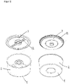
- figure 1 shows parts of a housing of a filter capsule according to the invention. At the edge of the bottom 1 of the housing there extends a side wall 2 which in this case has a cylinder-like shape.
- the cover 3 is attached reversibly or irreversibly to the side wall 2 .
- the cover has at least one fluid channel 12 .
- FIG. 2 shows different views of a filter capsule according to the invention.
- the base 1 is monolithically connected to the side wall 2 and the side wall 2 is irreversibly connected to the cover 3.
- the filter element 4 is arranged in the housing formed from the base 1, side wall 2 and cover 3.
- a circular elevation 5 on the bottom 1 and a circular elevation 33 on the cover 3 prevent liquid in the filter capsule from being able to flow past the filter element 4 .
- the base 1 has an indentation 6 which has a bulge 7 in the direction of the filter element 4 and a base groove 8 .
- a fluid channel 17 of the filter capsule, which extends along the side wall 2, is also shown.
- This filter capsule also contains a catch screen 18 to catch macroscopic particles and fibers of the filter element 4 and hold them back.
- the filter capsule has a predetermined breaking point 13 in the cover (here: a membrane), which breaks in the event of excess pressure. Liquid can thus flow past the filter element 4 directly from the inlet to the outlet of the filter capsule ("bypass"). Consequently, a possible destruction of the filter capsule due to excess pressure can be avoided.
- FIG. 3 shows further different views of a filter capsule according to the invention.
- the base 1 is also here monolithically connected to the side wall 2 and the side wall 2 is irreversibly connected to the cover 3 .
- the filter element 4 is arranged in the housing formed from the base 1, side wall 2 and cover 3.
- a circular elevation 5 on the bottom 1 and a circular elevation 33 on the cover 3 prevent liquid in the filter capsule from being able to flow past the filter element 4 .
- the base 1 has an indentation 6 which has a bulge 7 in the direction of the filter element 4 and a base groove 8 .
- a fluid channel 12 located in the cover 3 is also shown.
- a fluid channel 17 of the filter capsule, which extends along the side wall 2, is also shown.
- the arrangement is one Lateral surface groove 32 of the indentation 6 of the bottom 1 of the housing highlighted, which facilitates the connection of an adapter capsule to the filter capsule.
- This filter capsule also contains a predetermined breaking point 13 in the cover (here: a membrane), which breaks in the event of excess pressure and does not allow liquid to pass through the filter element 4, but instead short-circuits the inlet and outlet ("bypass"). Consequently, a possible destruction of the filter capsule due to excess pressure can be avoided.
- FIG 4 shows a cross section of a filter capsule according to the invention.
- the base 1 is also here monolithically connected to the side wall 2 and the side wall 2 is irreversibly connected to the cover 3 .
- the filter element 4 is arranged in the housing formed from the base 1, side wall 2 and cover 3.
- a circular elevation 5 on the bottom 1 and a circular elevation 33 on the cover 3 prevent liquid in the filter capsule from being able to flow past the filter element 4 .
- the base 1 has an indentation 6 which has a bulge 7 in the direction of the filter element 4 and a base groove 8 .
- a fluid channel 17 of the filter capsule, which extends along the side wall 2, is also shown.
- a side surface groove 32 of the indentation 6 of the base 1 of the housing is emphasized, which facilitates the connection of an adapter capsule to the filter capsule.
- a strainer 18 to catch and hold back macroscopic particles and fibers of the filter element 4 and a sealing surface 30 located in the cover 3 for the supply of liquid and a sealing surface 31 located in the cover 3 for the drainage of liquid.
- the base 1 here has a base area 1' which is elastic (elastic material or small thickness). This has the advantage that in the event of excess pressure in the filter capsule, liquid is not retained by the sealing of the circular elevation 5 on the bottom 1 of the housing. Rather, under these conditions, liquid can flow past the filter element 4 ("bypass") and pressure-related damage to the filter capsule can be avoided.
- FIG. 5 shows schematically the structure of a filter element according to the invention.
- the base 1 is also here monolithic with the side wall 2.
- a filter element 4 is inserted in the monolithic piece of base 1 and side wall 2.
- a strainer 18 is placed on the filter element 4 to catch and hold back macroscopic particles and fibers of the filter element 4 during operation of the filter capsule.
- a fluid channel disk 14 is placed on the catch screen 18 and has a continuous recess 15 in its center and contains at least one fluid channel 16 .
- the cover 3 is placed on this fluid channel disk 14 and can be reversibly or irreversibly connected to the side wall 2 in order to close the housing.
- the cover 3 has a fluid inlet 9 and a fluid outlet 10, which can optionally be closed using a sealing film 34 in order to increase the long-term stability of the filter capsule during storage.
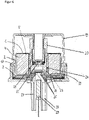
- FIG 6 shows a cross section of a filter capsule according to the invention, which is inserted into an adapter capsule 19 .
- the bottom 1 of the filter capsule is monolithically connected to the side wall 2 and the side wall 2 is irreversibly connected to the cover 3.
- the filter element 4 is arranged in the housing formed from the base 1, side wall 2 and cover 3.
- a circular elevation 5 on the bottom 1 and a circular elevation 33 on the cover 3 prevent liquid in the filter capsule from being able to flow past the filter element 4 .
- a fixing element 20 of the adapter capsule 19 is arranged in an indentation on the bottom 1 of the filter capsule, with the fixing element 20 being positively connected to the filter capsule via a side surface bulge 24 of the adapter capsule 19 in a side surface groove of the indentation on the bottom 1 of the filter capsule.
- a spring element 21 of the adapter capsule 19 exerts spring pressure on the filter capsule and presses it against an inlet 27 and an outlet 28 of a coffee machine.
- a sealing ring 25 and a silicone seal 26 of the adapter capsule 19 ensure that no liquid runs past the filter capsule.
- the adapter capsule 19 also has a magnet 22 with which it can be detected whether a filter capsule is inserted into the adapter capsule 19 or not. The detection can take place, for example, via a sensor 29 of the coffee machine.
Description
Es wird eine Filterkapsel zur Nachfiltration von extrahiertem Kaffee bereitgestellt, die dadurch gekennzeichnet ist, dass sie ein Gehäuse und mindestens ein Filterelement enthält oder daraus besteht. Das Gehäuse enthält einen Boden, mindestens eine Seitenwand und mindestens einen Deckel oder besteht daraus, wobei das mindestens eine Filterelement in einem Innenraum des Gehäuses angeordnet ist. Mit der erfindungsgemäßen Filterkapsel ist es möglich, an einem Brühsieb extrahierten Kaffee einer Nachfiltration zu unterziehen, sodass suspendierte Partikel und emulgierte Öle bestimmter Größe durch das Filterelement der Filterkapsel vom Kaffee abgetrennt werden und ein neuartiger Kaffee entsteht. Es wird daher die Verwendung der erfindungsgemäßen Filterkapsel zur Nachfiltration von Kaffee vorgeschlagen.A filter capsule for post-filtration of extracted coffee is provided, characterized in that it contains or consists of a housing and at least one filter element. The housing contains or consists of a base, at least one side wall and at least one cover, with the at least one filter element being arranged in an interior space of the housing. With the filter capsule according to the invention, it is possible to subject coffee extracted on a brewing sieve to post-filtration, so that suspended particles and emulsified oils of a certain size are separated from the coffee by the filter element of the filter capsule and a new type of coffee is produced. It is therefore proposed to use the filter capsule according to the invention for post-filtration of coffee.
Kaffeemaschinen zur Zubereitung von druckextrahierten Kaffee-Spezialitäten (z.B. Espresso oder Cappuccino) nutzen in aller Regel Brühsysteme, bei denen das Kaffeegetränk unter Druck (ca. 4-16 bar) gebrüht wird. Hierzu werden Brühsiebe eingesetzt, welche automatisch reinigbar sind und ein Zusetzen der Brühsiebe durch Ablagerungen von Bestandteilen der Kaffeebohne (z.B. unlösliche Bestandteile der gemahlene Kaffeebohnen und Kaffeeöle) während dem Betrieb vermeiden. Das Zusetzen der Brühsiebe wird im Allgemeinen durch relativ große Siebdurchlässe (d.h. weitmaschige Sieblöcher) erreicht. Für bestimmte Kaffee-Spezialitäten wie Espresso und Cappuccino sind Partikel, welche hierbei die relativ groben Sieblöcher passieren, sogar erwünscht. Diese sind mitverantwortlich für den besonderen Geschmack dieser Kaffee-Spezialitäten.Coffee machines for preparing pressure-extracted coffee specialties (e.g. espresso or cappuccino) generally use brewing systems in which the coffee drink is brewed under pressure (approx. 4-16 bar). For this purpose, brewing sieves are used, which can be cleaned automatically and prevent clogging of the brewing sieves by deposits of components of the coffee beans (e.g. insoluble components of the ground coffee beans and coffee oils) during operation. Clogging of the brewing screens is generally achieved through relatively large screen apertures (i.e., wide mesh screen holes). For certain coffee specialties such as espresso and cappuccino, particles that pass through the relatively coarse sieve holes are even desirable. These are partly responsible for the special taste of these coffee specialties.
Zudem entsteht bei der Druckbrühung dieser Kaffee-Spezialitäten durch Druckabfall am Brühsieb eine sogenannte "Crema", die sich hauptsächlich auch emulgierten Kaffeeölen zusammensetzt, aber auch Partikel und teilweise expandiertes CO2 enthält. Die "Crema" ist bei diesen Kaffee-Spezialitäten ebenfalls erwünscht, da sie zur Optik bzw. zum Geschmack beiträgt.In addition, during the pressure brewing of these coffee specialties, a so-called "crema" is created due to the pressure drop on the brewing sieve, which is mainly composed of emulsified coffee oils, but also contains particles and partially expanded CO 2 . The "crema" is also desirable with these coffee specialties, as it contributes to the look and taste.
Klassischer Filterkaffee weist dagegen nahezu keine Partikel und auch keine "Crema" auf. Der Grund hierfür ist, dass klassischer Filterkaffee in aller Regel ohne beaufschlagten Druck gebrüht wird d.h. der Brühdruck entspricht meist nur dem hydrostatischen Druck der Wassersäule über dem Filterboden, Zumindest werden bei der Herstellung von klassischem Filterkaffee keine Extraktionsdrücke wie bei der Espressoherstellung (ca. 4-16 bar) erreicht. Die Folge hiervon ist, dass die Herstellung von klassischem Filterkaffee mit hohen Brühzeiten verbunden ist. Da zudem bei dessen Herstellung deutlich feinere (d.h. engmaschigere) Siebe verwendet werden (Porendurchmesser im Bereich von 1 bis 50 µm) weisen die Siebböden dieser Siebe oft eine größere Fläche auf. Dies verhindert, dass die Extraktionszeit nicht unnötig verlängert wird. Oft sind die hier verwendeten Siebe aus Papier und/oder Metall hergestellt.Classic filter coffee, on the other hand, has almost no particles and no "crema". The reason for this is that classic filter coffee is usually brewed without any pressure being applied, i.e. the brewing pressure usually only corresponds to the hydrostatic pressure of the water column above the filter base. 16 bar) is reached. The consequence of this is that the production of classic filter coffee involves long brewing times. Since significantly finer (i.e. more closely meshed) sieves are also used in its production (pore diameter in the range from 1 to 50 µm), the sieve bottoms of these sieves often have a larger area. This prevents the extraction time from being unnecessarily increased. The screens used here are often made of paper and/or metal.
Die
Die
Die
Die
Die
Ausgehend hiervon war es die Aufgabe der vorliegenden Erfindung eine Vorrichtung bereitzustellen, mit der es möglich ist, optional im Zusammenwirken mit Kaffeemaschinen zur Zubereitung von (druck-)extrahierten Kaffee-Spezialitäten, einen extrahierten Kaffee mit geringem Gehalt an dispergierten Partikeln bereitzustellen.Proceeding from this, it was the object of the present invention to provide a device with which it is possible, optionally in conjunction with coffee machines for preparing (pressure) extracted coffee specialties, an extracted coffee with a low content of dispersed provide particles.
Die Aufgabe wird gelöst durch die Filterkapsel zur Nachfiltration von extrahiertem Kaffee mit den Merkmalen von Anspruch 1 und die Verwendung der Filterkapsel mit den Merkmalen von Anspruch 15. Die abhängigen Ansprüche zeigen vorteilhafte Weiterbildungen auf.The object is achieved by the filter capsule for post-filtration of extracted coffee having the features of
Erfindungsgemäß wird eine Filterkapsel zur Nachfiltration von extrahiertem, bevorzugt druckextrahierten, Kaffee bereitgestellt, wobei die Filterkapsel ein Gehäuse und mindestens ein Filterelement enthält oder daraus besteht. Das Gehäuse enthält einen Boden, mindestens eine Seitenwand und mindestens einen Deckel oder besteht daraus und das mindestens eine Filterelement ist in einem Innenraum des Gehäuses angeordnet. Die Filterkapsel ist dadurch gekennzeichnet, dass der Deckel mindestens einen durchgehenden Fluideinlass aufweist, der benachbart zu einer Mittelachse einer Grundfläche des Deckels angeordnet ist, und der Deckel mindestens einen durchgehenden Fluidauslass aufweist.According to the invention, a filter capsule is provided for post-filtration of extracted, preferably pressure-extracted, coffee, the filter capsule containing or consisting of a housing and at least one filter element. The housing contains or consists of a base, at least one side wall and at least one cover and the at least one filter element is arranged in an interior space of the housing. The filter capsule is characterized in that the lid has at least one continuous fluid inlet, which is arranged adjacent to a central axis of a base surface of the lid, and the lid has at least one continuous fluid outlet.
Durch das Filterelement in der Filterkapsel kann in der erfindungsgemäßen Filterkapsel ein Filtrationsprozess stattfinden, der einem Brühvorgang von Kaffee unter Druck nachgeschaltet ist. Durch das Filterelement in der Filterkapsel können dem druckextrahierten Kaffee feinste Bestandteile, d.h. im (druck-)extrahierten Kaffee befindliche suspendierte Partikel (z.B. Sedimente und emulgierte Kaffeeöle) entzogen werden. Durch Abfiltrieren der Kaffeeöle bzw. den Filtrationsvorgang an sich wird eine evtl. entstandene "Crema" abgefiltert bzw. zerstört. Durch das Filtrieren des (druck-)extrahierten Kaffees durch das Filterelement der Filterkapsel erhält das Kaffeegetränk somit einen anderen Geschmack und aufgrund dem Fehlen der feinsten, dispergierten Bestandteile, als auch der "Crema", eine deutlich andere Optik, Folglich ist ein entscheidender Vorteil der erfindungsgemäßen Filterkapsel, dass ein Kaffeeprodukte bereitgestellt werden kann, dass sich von klassischem (druck-)gebrühten Kaffee unterscheidet. Das Kaffeeprodukt ist geschmacklich nah am bzw. sogar besser als klassischer Filterkaffee und lässt sich auch in kleinen Mengen (z.B. tassenweise) mit einer von druckextrahierten Kaffeemaschinen bekannten Geschwindigkeit bereitstellen.Through the filter element in the filter capsule, a filtration process can take place in the filter capsule according to the invention, which follows a brewing process of coffee under pressure. The filter element in the filter capsule allows the finest components, ie suspended particles (eg sediments and emulsified coffee oils) in the (pressure) extracted coffee, to be removed from the pressure-extracted coffee. By filtering off the coffee oils or the filtration process itself, any "crema" that may have formed is filtered off or destroyed. By filtering the (pressure) extracted coffee through the filter element of the filter capsule, the coffee beverage gets a different taste and due to the lack of the finest, dispersed components, as well as the "crema", a significantly different appearance. Consequently, a decisive advantage is the filter capsule according to the invention that a coffee product can be provided that differs from classic (pressure) brewed coffee. The coffee product tastes close to or even better than classic filter coffee and can also be used in small Deliver quantities (e.g. by the cup) at a rate known from pressure-extracted coffee machines.
Wird die erfindungsgemäße Filterkapsel zusammen mit einer druckextrahierenden Kaffeemaschine verwendet, können sowohl klassische druckextrahierte Kaffeeprodukte als auch ein Kaffeeprodukt bereitgestellt werden, das sehr ähnlich bis identisch zu einem klassischen Filterkaffee ist. Folglich können dem Bediener der Kaffeemaschine auf schnelle Art und Weise in Tassenvolumen unterschiedliche Geschmackserlebnisse geboten werden.If the filter capsule according to the invention is used together with a pressure-extracting coffee machine, both classic pressure-extracted coffee products and a coffee product that is very similar or identical to a classic filter coffee can be provided. Consequently can the operator of the coffee machine can quickly be offered different taste experiences in cup volumes.
Ein weiterer Vorteil ist, dass die Filterkapsel kostengünstig herstellbar und einfach in der Handhabung ist. Es kann beispielsweise in einer Kaffeemaschine ein Aufnahmebereich vorgesehen sein, in dem die Filterkapsel auf einfache Art und Weise an die Kaffeemaschine angebunden bzw. angeschlossen werden kann und auch auf einfache Art und Weise wieder von der Kaffeemaschine entfernt werden kann. Denkbar sind hierbei Aufnahmebereiche, wie sie bereits von Kaffeemaschinen bekannt sind, in welche mit Kaffee gefüllte Kapseln angebunden werden.A further advantage is that the filter capsule can be produced inexpensively and is easy to handle. A receiving area can be provided in a coffee machine, for example, in which the filter capsule can be attached or attached to the coffee machine in a simple manner and can also be removed from the coffee machine again in a simple manner. Receiving areas are conceivable here, as are already known from coffee machines, in which capsules filled with coffee are attached.
Das Filterelement der Filterkapsel kann mindestens einen Filter enthalten, der bevorzugt eine maximale Porengröße von 80 µm aufweist und bevorzugt eine Dicke von 0,1 mm bis 10 mm aufweist. Das Filterelement kann mindestens einen Feinfilter enthalten, der bevorzugt eine maximale Porengröße von 25 µm aufweist und besonders bevorzugt eine Dicke von 0,1 mm bis 10 mm aufweist. Das Filterelement kann mindestens einen Feinstfilter enthalten, der bevorzugt eine maximale Porengröße von 10 µm aufweist und besonders bevorzugt eine Dicke von 0,1 mm bis 10 mm aufweist. Das Filterelement kann auch mindestens einen (z.B. oben genannten) Filter, mindestens einen Feinfilter und mindestens einen Feinstfilter enthalten oder daraus bestehen. Besonders bevorzugt ist der mindestens eine Feinfilter stromabwärts des Filters und der mindestens eine Feinstfilter stromabwärts des Feinfilters angeordnet.The filter element of the filter capsule can contain at least one filter, which preferably has a maximum pore size of 80 μm and preferably has a thickness of 0.1 mm to 10 mm. The filter element can contain at least one fine filter, which preferably has a maximum pore size of 25 μm and particularly preferably has a thickness of 0.1 mm to 10 mm. The filter element can contain at least one ultra-fine filter, which preferably has a maximum pore size of 10 μm and particularly preferably has a thickness of 0.1 mm to 10 mm. The filter element can also contain or consist of at least one filter (e.g. as mentioned above), at least one fine filter and at least one ultra-fine filter. The at least one fine filter is particularly preferably arranged downstream of the filter and the at least one ultra-fine filter is arranged downstream of the fine filter.
Bevorzugt ist, dass die maximalen Porengröße (Maschigkeit) des Feinfilters kleiner ist als des Filters und die maximale Porengröße des Feinstfilters kleiner ist als des Feinfilters. Die Ausstattung des Filterelements mit einem Feinfilter und/oder Feinstfilter hat den Vorteil, dass stufenweise kleinere Partikel von dem Kaffee getrennt werden können. Zudem kann mit der resultierenden Mehrlagigkeit des Filterelements eine deutlich höhere Kapazität des Filterelements erreicht werden als wenn nur ein Filter, Feinfilter oder Feinstfilter verwendet wird. Die zur Verfügung stehende Filterfläche wird daher optimal ausgenutzt.It is preferred that the maximum pore size (mesh size) of the fine filter is smaller than that of the filter and the maximum pore size of the superfine filter is smaller than that of the fine filter. Equipping the filter element with a fine filter and/or ultra-fine filter has the advantage that smaller particles can be gradually separated from the coffee. In addition, with the resulting multiple layers of the filter element, a significantly higher capacity of the filter element can be achieved than if only one filter, fine filter or ultra-fine filter is used. The available filter surface is therefore optimally utilized.
Die maximale Porengröße eines Elements (z.B. des Filterelements bzw. des Filters, des Feinfilters und Feinstfilters und auch des Brühsiebs) kann auf einfache Art und Weise dadurch bestimmt werden, indem eine Dispersion von Partikeln bekannter Größenverteilung durch das Element geströmt wird und anschließend die Größenverteilung der Partikel auf der Seite des Eintritts der Dispersion und/oder der Seite des Austritts der Dispersion über ein mikroskopisches Verfahren bestimmt wird.The maximum pore size of an element (e.g. the filter element or the filter, the fine filter and ultra-fine filter and also the brewing sieve) can be determined in a simple manner by flowing a dispersion of particles of known size distribution through the element and then measuring the size distribution of the Particles on the side of entry of the dispersion and/or the side of exit of the dispersion is determined by a microscopic method.
Das Filterelement kann eine Länge, eine Breite und/oder einen Durchmesser im Bereich von 1 bis 10 cm, bevorzugt 2 bis 9 cm, besonders bevorzugt 3 bis 8 cm, ganz besonders bevorzugt 4 bis 7 cm, insbesondere 5 bis 6 cm, aufweisen.The filter element can have a length, a width and/or a diameter in the range from 1 to 10 cm, preferably 2 to 9 cm, particularly preferably 3 to 8 cm, very particularly preferably 4 to 7 cm, in particular 5 to 6 cm.
Das Filterelement kann eine Höhe in einem Bereich von 1 bis 14 cm, bevorzugt 2 bis 12 cm, besonders bevorzugt 3 bis 10 cm, ganz besonders bevorzugt 4 bis 8 cm, insbesondere 5 bis 6 cm, aufweisen. Die Größenskalierung des Filterelements, was mit der Reichweite des Filters korreliert, kann über die Höhe des Filterelements erfolgen, d.h. die Breite und Länge des Filterelements kann unverändert bleiben. Beim Gehäuse der Filterkapsel muss entsprechend nur die Länge der mindestens einen Seitenwand angepasst werden, was den Vorteil hat, dass der Boden und der Deckel mit allen seinen Bestandteilen unverändert bleiben kann.The filter element can have a height in a range from 1 to 14 cm, preferably 2 to 12 cm, particularly preferably 3 to 10 cm, very particularly preferably 4 to 8 cm, in particular 5 to 6 cm. The size scaling of the filter element, which correlates with the range of the filter, can be done via the height of the filter element, i.e. the width and length of the filter element can remain unchanged. In the case of the filter capsule housing, only the length of at least one side wall has to be adjusted accordingly, which has the advantage that the base and the cover with all of their components can remain unchanged.
Das Filterelement, bevorzugt mindestens ein Filter, mindestens ein Feinfilter und/oder mindestens ein Feinstfilter des Filterelements kann
- i) Papier; und/oder
- ii) Kunststoff; und/oder
- iii) Metall;
- i) paper; and or
- ii) plastic; and or
- iii) metal;
Das Filterelement, bevorzugt mindestens ein Filter, mindestens ein Feinfilter und/oder mindestens ein Feinstfilter des Filterelements können im Wesentlichen in Form eines geraden oder schiefen Zylinders ausgestaltet sein. Optional weist der Zylinder eine gerade oder schiefe zylindrische Ausnehmung in der Mitte des Zylinders auf. Der Zylinder weist bevorzugt eine, optional mit einem Loch in der Mitte versehene, Grundfläche auf, die ausgewählt ist aus der Gruppe bestehend aus kreisförmige Grundfläche, halbkreisförmige Grundfläche, sichelförmige Grundfläche, elliptische Grundfläche und Grundfläche mit mindestens zwei Ecken. Eine kreisförmige Grundfläche ist besonders bevorzugt.The filter element, preferably at least one filter, at least one fine filter and/or at least one ultra-fine filter of the filter element can essentially be configured in the form of a straight or skewed cylinder. Optionally, the cylinder has a straight or oblique cylindrical recess in the center of the cylinder. The cylinder preferably has a base, optionally provided with a central hole, selected from the group consisting of circular base, semi-circular base, crescent-shaped base, elliptical base and base with at least two corners. A circular base is particularly preferred.
Das Filterelement, bevorzugt mindestens ein Filter, mindestens ein Feinfilter und/oder mindestens ein Feinstfilter des Filterelements, kann von Fluid, bevorzugt von einer wässrigen Lösung, besonders bevorzugt von Kaffee,
- i) radial anströmbar sein, bevorzugt von stromaufwärts kommenden Fluid radial in Richtung zu einer Achse des Zylinders anströmbar sein und/oder von stromabwärts kommenden Fluid radial in Richtung weg von einer Achse des Zylinders anströmbar sein; und/oder
- ii) axial anströmbar sein, bevorzugt von stromaufwärts kommenden Fluid in Richtung entlang einer Achse des Zylinders von einer Oberseite des Filterelements zu einer Unterseite des Filterelements anströmbar sein und/oder von stromabwärts kommenden Fluid in Richtung entlang einer Achse des Zylinders von einer Unterseite des Filterelements zu einer Oberseite des Filterelements anströmbar sein.
- i) be able to flow radially, preferably fluid coming upstream can flow radially in the direction of an axis of the cylinder and/or fluid coming downstream can flow radially in the direction away from an axis of the cylinder; and or
- ii) be able to flow axially, preferably by fluid coming upstream in a direction along an axis of the cylinder from a top side of the filter element to a bottom side of the filter element and/or by fluid coming downstream in a direction along an axis of the cylinder from a bottom side of the filter element an upper side of the filter element can be flowed against.
Die radiale Anströmung hat den Vorteil, dass das Filterelement bei einer bestimmten Siebfläche eine kleinere maximale Raumausdehnung aufweist als bei der axialen Anströmung. Ferner kann somit auf einfache Art und Weise der Fluideingang und Fluidausgang der Filterkapsel auf (nur) einer bestimmten Seite (z.B. im Deckel der Filterkapsel) realisiert werden. Es ist von Vorteil, wenn die Engmaschigkeit der eingesetzten Siebe in Strömungsrichtung zunimmt d.h. das Fluid beispielsweise erst durch einen Filter (Außenmantel des Zylinders), dann durch einen Feinfilter (Mittelmantel des Zylinders) und anschließend durch einen Feinstfilter (Innenmantel des Zylinders) strömt. Hier hat die radiale Anströmung den Vorteil, dass sie bei vergleichbarer Filtrationsqualität ökonomischer und ökologischer ist als die axiale Anströmung, da die Fläche des Feinstfilters kleiner ist als die Fläche des Feinfilters und die Fläche des Feinfilters kleiner ist als die Fläche des Filters.The radial flow has the advantage that the filter element has a smaller maximum spatial extent for a specific screen area than with the axial flow. Furthermore, the fluid inlet and fluid outlet of the filter capsule can thus be implemented in a simple manner on (only) one specific side (for example in the cover of the filter capsule). It is advantageous if the mesh size of the screens used increases in the direction of flow ie the fluid flows, for example, first through a filter (outer shell of the cylinder), then through a fine filter (middle shell of the cylinder) and then through a micro-filter (inner shell of the cylinder). Here, the radial flow has the advantage that it is more economical and ecological than the axial flow with comparable filtration quality, since the surface of the ultra-fine filter is smaller than the surface of the fine filter and the surface of the fine filter is smaller than the surface of the filter.
Der Boden der Filterkapsel kann eine Grundfläche mit einer Länge, einer Breite und/oder einem Durchmesser aufweisen, die/der größer ist als die Länge, die Breite und/oder der Durchmesser der Grundfläche des Filterelements, bevorzugt 0,01 bis 5 mm, besonders bevorzugt 0,05 bis 4 mm, ganz besonders bevorzugt 0,1 bis 3 mm, insbesondere 0,2 bis 2 mm, größer. Optional ist die Länge, Breite und/oder der Durchmesser des Deckels größer ist als des Bodens.The bottom of the filter capsule can have a base with a length, a width and/or a diameter which is larger than the length, the width and/or the diameter of the base of the filter element, preferably 0.01 to 5 mm, in particular preferably 0.05 to 4 mm, very particularly preferably 0.1 to 3 mm, in particular 0.2 to 2 mm, larger. Optionally, the length, width and/or diameter of the lid is greater than that of the base.
Der Boden der Filterkapsel kann auf einer dem mindestens einen Filterelement zugewandten Seite mindestens eine Erhebung, bevorzugt mindestens eine kreisförmige Erhebung, aufweisen, die sich in Richtung Filterelement erstreckt, bevorzugt in Richtung eines Feinstfilters des Filterelements erstreckt, und den Raum zwischen Boden und Filterelement flüssigkeitsdicht verschließt. Die Erhebung bewirkt, dass in die Filterkapsel (durch einen Zulauf) einströmende Flüssigkeit das Filterelement passiert und schließlich die Filterkapsel (durch einen Auslauf) verlässt, also nicht am Filterelement vorbei läuft. Die Erhebung hat somit die Funktion eines Dichtelements.The bottom of the filter capsule can have at least one elevation, preferably at least one circular elevation, on a side facing the at least one filter element, which extends in the direction of the filter element, preferably in the direction of an ultra-fine filter of the filter element, and closes the space between the bottom and the filter element in a liquid-tight manner . The elevation causes liquid flowing into the filter capsule (through an inlet) to pass the filter element and finally leave the filter capsule (through an outlet), i.e. it does not run past the filter element. The survey thus has the function of a sealing element.
Der Boden der Filterkapsel kann eine Dicke im Bereich von 0,1 bis 2 mm, bevorzugt 0,2 bis 1,5 mm, besonders bevorzugt 0,3 bis 1,0 mm, insbesondere 0,4 bis 0,5 mm, aufweisen.The bottom of the filter capsule can have a thickness in the range from 0.1 to 2 mm, preferably 0.2 to 1.5 mm, particularly preferably 0.3 to 1.0 mm, in particular 0.4 to 0.5 mm.
Der Boden der Filterkapsel kann einen elastischen Bereich enthalten oder daraus bestehen. Bevorzugt wird die Elastizität des elastischen Bereichs durch eine bestimmte Dicke, eine bestimmte Geometrie (z.B. Faltenbalg) und/oder ein bestimmtes Material bewirkt. Das bestimmte Material ist besonders bevorzugt ausgewählt aus der Gruppe bestehend aus Elastomeren und Thermoplasten. Insbesondere ist das Material ausgewählt aus der Gruppe bestehend aus Silikon, Kautschuk, Polypropylen, Polyethylen, Polystyrol und Mischungen hiervon.The bottom of the filter capsule may contain or consist of an elastic area. The elasticity of the elastic area is preferably brought about by a specific thickness, a specific geometry (eg bellows) and/or a specific material. The specific material is particularly preferably selected from the group consisting of elastomers and thermoplastics. In particular, the material is selected from the group consisting of made of silicone, rubber, polypropylene, polyethylene, polystyrene and mixtures thereof.
Ist der Boden zumindest bereichsweise elastisch ausgestaltet (z.B. durch ein elastisches Material oder eine geringe Dicke des Bodens) kann durch einen Überdruck im Inneren der Filterkapsel ein Auswölben des Bodens stattfinden, wobei Flüssigkeit am Filterelement vorbei fließen kann ("Bypass"). Eine Zerstörung der Filterkapsel durch Überdruck wird dadurch vermieden. Auch ein plötzliches Verstopfen des Filterelements aus irgendwelchen, nicht vorsehbaren Gründen (z.B. ein Defekt des Brühsiebes stromaufwärts der Filterkapsel) führt nicht zu einer Überdruck-bedingten Zerstörung der Filterkapsel. Es kann am Ergebnis in der Tasse erkannt werden, dass der Filter nicht mehr funktioniert, da sich in der Tasse dann klassischer druckgebrühter Kaffee befindet. Ferner kann die Wölbung des Bodens auch ein Signal in einem Drucksensor bewirken, der am Boden der Filterkapsel anliegt. Somit kann einer die Filterkapsel und den Drucksensor aufweisende Kaffeemaschine auch über diesem Weg die Information verarbeiten und ausgeben, dass ein Überdruck in der Filterkapsel herrscht und diese ausgetauscht werden muss.If the base is designed to be elastic at least in some areas (e.g. due to an elastic material or a low thickness of the base), the base can bulge due to overpressure inside the filter capsule, whereby liquid can flow past the filter element ("bypass"). This prevents the filter capsule from being destroyed by overpressure. Even a sudden clogging of the filter element for some unforeseeable reason (e.g. a defect in the brewing sieve upstream of the filter capsule) does not lead to the overpressure-related destruction of the filter capsule. It can be seen from the result in the cup that the filter is no longer working, as the cup then contains classic pressure-brewed coffee. Furthermore, the curvature of the bottom can also cause a signal in a pressure sensor that rests on the bottom of the filter capsule. Thus, a coffee machine having the filter capsule and the pressure sensor can also use this route to process and output the information that there is overpressure in the filter capsule and that it needs to be replaced.
Der Boden der Filterkapsel kann eine Einbuchtung aufweisen, die sich in Richtung des Deckels erstreckt, bevorzugt mindestens 25% der Höhe der mindestens einen Seitenwand, besonders bevorzugt mindestens 50% der Höhe der mindestens einen Seitenwand, ganz besonders bevorzugt mindestens 75% der Höhe der mindestens einen Seitenwand, insbesondere mindestens 90% der Höhe der mindestens einen Seitenwand.The bottom of the filter capsule can have an indentation that extends in the direction of the lid, preferably at least 25% of the height of the at least one side wall, more preferably at least 50% of the height of the at least one side wall, most preferably at least 75% of the height of the at least a side wall, in particular at least 90% of the height of the at least one side wall.
Die Einbuchtung des Bodens kann bevorzugt in einer zylindrischen Ausnehmung des Filterelements angeordnet sein.The indentation of the base can preferably be arranged in a cylindrical recess of the filter element.
Die Einbuchtung des Bodens kann mindestens eine sich in Richtung der mindestens einen Seitenwand erstreckende Rippe, bevorzugt mindestens zwei sich in Richtung der mindestens einen Seitenwand erstreckende Rippen, besonders bevorzugt mindestens vier sich in Richtung der mindestens einen Seitenwand erstreckende Rippen, enthalten. Ganz besonders bevorzugt sind jeweils zwei Rippen gegenüberliegend angeordnet. Insbesondere erstrecken sich die Rippen entlang der Einbuchtung des Bodens in Richtung Deckel, optional auf einer Länge, die mindestens 50% der Länge der mindestens einen Seitenwand beträgt. Die Rippe bzw. mehreren Rippen haben den Vorteil, dass das Filterelement in der Filterkapsel bzw. in dem Gehäuse der Filterkapsel ausgerichtet, fixiert und/oder zentriert wird.The indentation of the base can contain at least one rib extending in the direction of the at least one side wall, preferably at least two ribs extending in the direction of the at least one side wall, particularly preferably at least four ribs extending in the direction of the at least one side wall. Very particularly preferably, two ribs are arranged opposite each other. In particular, the ribs extend along the indentation of the base towards the lid, optionally to a length that is at least 50% of the length of the at least one sidewall. The rib or several ribs have the advantage that the filter element is aligned, fixed and/or centered in the filter capsule or in the housing of the filter capsule.
Die Einbuchtung des Bodens kann eine Grundflächennut enthalten, die bevorzugt in einer parallel zum Deckel angeordneten Grundfläche der Einbuchtung angeordnet ist, besonders bevorzugt konzentrisch um eine Mittelachse einer Grundfläche des Deckels angeordnet ist. Die Grundflächennut kann dazu dienen, eine Ausbuchtung einer zur Aufnahme der Filterkapsel vorgesehene Adapterkapsel aufzunehmen und somit die Filterkapsel in der Adapterkapsel zu fixieren und/oder zentrieren.The indentation of the base can contain a base surface groove, which is preferably arranged in a base surface of the indentation arranged parallel to the cover, particularly preferably arranged concentrically around a central axis of a base surface of the cover. The base groove can serve to accommodate a bulge of an adapter capsule provided for receiving the filter capsule and thus to fix and/or center the filter capsule in the adapter capsule.
Die Einbuchtung des Bodens kann eine Seitenflächennut enthalten, die bevorzugt in einer im Wesentlichen senkrecht zum Deckel angeordneten Seitenfläche der Einbuchtung angeordnet ist, besonders bevorzugt konzentrisch um eine Mittelachse einer Grundfläche des Deckels angeordnet ist. Die Seitenflächennut kann dazu dienen, eine Ausbuchtung einer zur Aufnahme der Filterkapsel vorgesehene Adapterkapsel aufzunehmen und somit die Filterkapsel in der Adapterkapsel zu fixieren und/oder zentrieren.The indentation of the base can contain a side surface groove, which is preferably arranged in a side surface of the indentation arranged essentially perpendicularly to the cover, particularly preferably arranged concentrically around a central axis of a base area of the cover. The lateral surface groove can serve to accommodate a bulge of an adapter capsule provided for receiving the filter capsule and thus to fix and/or center the filter capsule in the adapter capsule.
Die mindestens eine Seitenwand der Filterkapsel kann eine Höhe aufweisen, die größer ist als die Höhe des Filterelements bevorzugt 0,01 bis 5 mm, besonders bevorzugt 0,05 bis 4 mm, ganz besonders bevorzugt 0,1 bis 3 mm, insbesondere 0,2 bis 2 mm, größer.The at least one side wall of the filter capsule can have a height that is greater than the height of the filter element, preferably 0.01 to 5 mm, particularly preferably 0.05 to 4 mm, very particularly preferably 0.1 to 3 mm, in particular 0.2 up to 2 mm, larger.
Die mindestens eine Seitenwand der Filterkapsel kann reversibel mit dem Deckel verbunden sein, bevorzugt über eine formschlüssige und/oder kraftschlüssige Verbindung, besonders bevorzugt über eine Schraubverbindung oder Klemmverbindung (Mehrweglösung). Der Vorteil an dieser Ausgestaltungsform ist, dass die Filterkapsel vom Benutzer geöffnet und verschlossen werden kann, um das Filterelement auszutauschen.The at least one side wall of the filter capsule can be reversibly connected to the cover, preferably via a positive and/or non-positive connection, particularly preferably via a screw connection or clamp connection (reusable solution). The advantage of this embodiment is that the filter capsule can be opened and closed by the user in order to replace the filter element.
Die mindestens eine Seitenwand der Filterkapsel kann irreversibel mit dem Deckel verbunden sein, bevorzugt über eine stoffschlüssige Verbindung, besonders bevorzugt über eine Schweißverbindung oder Klebeverbindung (Einweglösung). Der Vorteil an dieser Ausgestaltungsform ist, dass im Gegensatz zur Mehrweglösung keine Probleme mit der Dichtigkeit der Filterkapsel an der Schnittstelle zwischen dem Deckel und der mindestens einen Seitenwand auftreten können.The at least one side wall of the filter capsule can be irreversibly connected to the cover, preferably via a material connection, particularly preferably via a welded connection or adhesive connection (disposable solution). The advantage of this embodiment is that, in contrast to the reusable solution, no problems with the tightness of the filter capsule can occur at the interface between the cover and the at least one side wall.
Die mindestens eine Seitenwand der Filterkapsel kann eine Dicke im Bereich von 0,1 bis 2 mm, bevorzugt 0,2 bis 1,5 mm, besonders bevorzugt 0,3 bis 1,0 mm, insbesondere 0,4 bis 0,5 mm, aufweisen.The at least one side wall of the filter capsule can have a thickness in the range from 0.1 to 2 mm, preferably 0.2 to 1.5 mm, particularly preferably 0.3 to 1.0 mm, in particular 0.4 to 0.5 mm. exhibit.
Die Seitenwand kann mindestens eine sich in Richtung des Filterelements erstreckende Rippe, bevorzugt mindestens zwei sich in Richtung des Filterelements erstreckende Rippen, besonders bevorzugt mindestens vier sich in Richtung des Filterelements erstreckende Rippen, enthalten. Ganz besonders bevorzugt sind jeweils zwei Rippen gegenüberliegend angeordnet. Insbesondere erstrecken sich die Rippen entlang der mindestens einen Seitenwand in Richtung Deckel, optional auf einer Länge, die mindestens 50% der Länge der mindestens einen Seitenwand beträgt. Die Rippe bzw. mehreren Rippen haben den Vorteil, dass das Filterelement in der Filterkapsel bzw. in dem Gehäuse der Filterkapsel ausgerichtet, fixiert und/oder zentriert wird.The side wall can contain at least one rib extending in the direction of the filter element, preferably at least two ribs extending in the direction of the filter element, particularly preferably at least four ribs extending in the direction of the filter element. Very particularly preferably, two ribs are arranged opposite each other. In particular, the ribs extend along the at least one side wall in the direction of the cover, optionally over a length which is at least 50% of the length of the at least one side wall. The rib or several ribs have the advantage that the filter element is aligned, fixed and/or centered in the filter capsule or in the housing of the filter capsule.
Die mindestens eine Seitenwand der Filterkapsel kann einen elastischen Bereich enthalten oder daraus bestehen. Bevorzugt wird die Elastizität des elastischen Bereichs durch eine bestimmte Dicke, eine bestimmte Geometrie (z.B. Faltenbalg) und/oder ein bestimmtes Material bewirkt. Das bestimmte Material ist besonders bevorzugt ausgewählt aus der Gruppe bestehend aus Elastomeren und Thermoplasten. Insbesondere ist das Material ausgewählt aus der Gruppe bestehend aus Silikon, Kautschuk, Polypropylen, Polyethylen, Polystyrol und Mischungen hiervon.The at least one side wall of the filter capsule can contain or consist of an elastic area. The elasticity of the elastic area is preferably brought about by a specific thickness, a specific geometry (e.g. bellows) and/or a specific material. The specific material is particularly preferably selected from the group consisting of elastomers and thermoplastics. In particular, the material is selected from the group consisting of silicone, rubber, polypropylene, polyethylene, polystyrene and mixtures thereof.
Ist die mindestens eine Seitenwand zumindest bereichsweise elastisch ausgestaltet (z.B. durch ein elastisches Material oder eine geringe Dicke des Bodens) kann durch einen Überdruck im Inneren der Filterkapsel ein Auswölben des der mindestens einen Seitenwand stattfinden. Dieses Auswölben kann ein Signal in einem Drucksensor bewirken, der an der mindestens einen Seitenwand der Filterkapsel anliegt. Somit kann eine die Filterkapsel und den Drucksensor aufweisende Kaffeemaschine die Information verarbeiten und ausgeausgeben, dass ein Überdruck in der Filterkapsel herrscht und diese ausgetauscht werden muss.If the at least one side wall is designed to be elastic at least in some areas (eg by means of an elastic material or a low thickness of the base), excess pressure inside the filter capsule can cause the at least one side wall to bulge. This bulging can cause a signal in a pressure sensor which is in contact with the at least one side wall of the filter capsule. Thus, a coffee machine having the filter capsule and the pressure sensor can process and output the information that there is overpressure in the filter capsule and that it needs to be replaced.
Der Deckel der Filterkapsel kann eine Grundfläche mit einer Länge, einer Breite und/oder einem Durchmesser aufweisen, die/der größer ist als die Länge, die Breite und/oder der Durchmesser der Grundfläche des Filterelements, bevorzugt 0,01 bis 5 mm, besonders bevorzugt 0,05 bis 4 mm, ganz besonders bevorzugt 0,1 bis 3 mm, insbesondere 0,2 bis 2 mm, größer, Optional ist die Länge, Breite und/oder der Durchmesser des Deckels größer ist als die Länge, Breite und/oder der Durchmesser des Bodens.The lid of the filter capsule can have a base with a length, a width and/or a diameter that is greater than the length, the width and/or the diameter of the base of the filter element, preferably 0.01 to 5 mm, in particular preferably 0.05 to 4 mm, very particularly preferably 0.1 to 3 mm, in particular 0.2 to 2 mm larger, optionally the length, width and/or the diameter of the lid is larger than the length, width and/or or the diameter of the bottom.
Der Deckel der Filterkapsel weist mindestens einen durchgehenden Fluideinlass auf (Einlass von Flüssigkeit von Zulauf einer Kaffeemaschine), der benachbart zu einer Mittelachse einer Grundfläche des Deckels angeordnet ist und besonders bevorzugt eine Membran zur Vermeidung von Abtropfen von Flüssigkeit aus der Filterkapsel enthält. Dies bewirkt, dass die Filterkapsel einen zentralen bzw. koaxialen Einlassanschluss an eine Kaffeemaschine aufweist, der ein richtungsunabhängiges Einsetzen des Filters ermöglicht.The lid of the filter capsule has at least one continuous fluid inlet (inlet of liquid from the inlet of a coffee machine) which is arranged adjacent to a central axis of a base area of the lid and particularly preferably contains a membrane to prevent liquid from dripping out of the filter capsule. This causes the filter capsule to have a central or coaxial inlet connection to a coffee machine, which enables the filter to be inserted in any direction.
Der Deckel der Filterkapsel weist mindestens einen durchgehenden Fluidauslass auf (Auslass von Flüssigkeit zu Ablauf einer Kaffeemaschine), der bevorzugt entlang einer Mittelachse einer Grundfläche des Deckels angeordnet ist und besonders bevorzugt eine Membran zur Vermeidung von Abtropfen von Flüssigkeit aus der Filterkapsel enthält. Dies bewirkt, dass die Filterkapsel einen zentralen bzw. koaxialen Auslassanschluss an eine Kaffeemaschine aufweist, der ein richtungsunabhängiges Einsetzen des Filters ermöglicht.The cover of the filter capsule has at least one continuous fluid outlet (outlet of liquid to the outlet of a coffee machine), which is preferably arranged along a central axis of a base area of the cover and particularly preferably contains a membrane to prevent liquid from dripping out of the filter capsule. This causes the filter capsule to have a central or coaxial outlet connection to a coffee machine, which enables the filter to be inserted in any direction.
Der Deckel der Filterkapsel kann auf einer dem mindestens einen Filterelement abgewandten Seite mindestens einen, bevorzugt mindestens zwei, besonders bevorzugt mindestens vier, insbesondere mindestens acht, Abstandshalter aufweisen, die optional monolithisch mit dem Deckel sind. Der bzw. die Abstandshalter verbessern die Stabilität der fluidischen Anbindung der Filterkapsel an einen Ablauf zu einer Kaffeemaschine.The cover of the filter capsule can have at least one, preferably at least two, particularly preferably at least four, in particular at least eight, spacers on a side facing away from the at least one filter element, which spacers are optionally monolithic with the cover. The spacer or spacers improve the stability of the fluidic connection of the filter capsule to a drain to a coffee machine.
Der Deckel der Filterkapsel kann auf einer dem mindestens einen Filterelement zugewandten Seite mindestens einen, bevorzugt mindestens zwei, besonders bevorzugt mindestens drei, insbesondere mindestens vier, Fluidkanäle aufweisen, die sich bevorzugt von einer Mitte einer Grundfläche des Deckels in Richtung mindestens einer Seitenwand der Filterkapsel erstrecken und besonders bevorzugt zu einer dem Deckel zugewandten Seite des Filterelements, optional über eine Fluidkanalscheibe, geschlossen sind. Die Anwesenheit mehrere Fluidkanäle hat den Vorteil, dass eine definiertere Flüssigkeitsströmung und eine gleichmäßigere Verteilung des Kaffeestroms zum Filterelement erzeugt wird. Durch diese Maßnahme kann die volle Kapazität des Filterelements genutzt werden und die Lebensdauer des Filters verlängert werden.The cover of the filter capsule can have at least one, preferably at least two, particularly preferably at least three, in particular at least four, fluid channels on a side facing the at least one filter element, which preferably extend from a center of a base area of the cover in the direction of at least one side wall of the filter capsule and are particularly preferably closed on a side of the filter element facing the cover, optionally via a fluid channel disk. The presence of several fluid channels has the advantage that a more defined liquid flow and a more even distribution of the coffee flow to the filter element is created. This measure allows the full capacity of the filter element to be used and the service life of the filter to be extended.
Der Deckel der Filterkapsel kann eine Sollbruchstelle aufweisen, bevorzugt eine Membran, die dazu geeignet ist, im Falle eines Überdrucks den Fluidstrom in der Filterkapsel an dem Filterelement vorbei zu lenken. Vorteil an dieser Ausgestaltungsform ist, dass im Falle eines (massiven) Überdrucks Flüssigkeit nicht über das Filterelement durch die Filterkapsel geleitet wird ("Bypass") und somit eine druckbedingte Zerstörung der Filterkapsel vermieden wird.The cover of the filter capsule can have a predetermined breaking point, preferably a membrane, which is suitable for directing the fluid flow in the filter capsule past the filter element in the event of excess pressure. The advantage of this embodiment is that in the event of a (massive) excess pressure, liquid is not routed via the filter element through the filter capsule (“bypass”) and thus pressure-related destruction of the filter capsule is avoided.
Der Deckel der Filterkapsel kann eine Dichtungsfolie aufweisen, die einen Fluideinlass und/oder Fluidauslass des Deckels fluiddicht verschließt. Vorteil hierbei ist, dass beim Entfernen der Filterkapsel aus einer Kaffeemaschine kein Auslaufen von Flüssigkeit (Kaffee) aus der Filterkapsel stattfindet.The cover of the filter capsule can have a sealing film that seals a fluid inlet and/or fluid outlet of the cover in a fluid-tight manner. The advantage here is that when the filter capsule is removed from a coffee machine, there is no leakage of liquid (coffee) from the filter capsule.
Der Deckel der Filterkapsel kann auf einer dem mindestens einen Filterelement zugewandten Seite mindestens eine Erhebung, bevorzugt mindestens eine kreisförmige Erhebung, aufweisen, die sich in Richtung Filterelement erstreckt, bevorzugt in Richtung eines Feinstfilters des Filterelements erstreckt, und den Raum zwischen Deckel und Filterelement flüssigkeitsdicht verschließt. Die Erhebung bewirkt, dass in die Filterkapsel (durch einen Zulauf) einströmende Flüssigkeit das Filterelement passiert und schließlich die Filterkapsel (durch einen Auslauf) verlässt, also nicht am Filterelement vorbei läuft. Die Erhebung hat somit die Funktion eines Dichtelements.The cover of the filter capsule can have at least one elevation, preferably at least one circular elevation, on the side facing the at least one filter element, which extends in the direction of the filter element, preferably in the direction of an ultra-fine filter of the filter element, and closes the space between the cover and the filter element in a liquid-tight manner . The elevation causes liquid flowing into the filter capsule (through an inlet) to pass the filter element and finally leave the filter capsule (through an outlet), i.e. it does not run past the filter element. The survey thus has the function of a sealing element.
Ferner kann der Deckel der Filterkapsel eine Abdichtungsfolie enthalten. Mit der Abdichtungsfolie kann ein Fluideinlass und Fluidauslass des Deckels reversibel verschlossen werden, was die Langzeitbeständigkeit der Filterkapsel während ihrer Lagerung bis zum Gebrauch erhöht und die Filterkapsel hygienischer macht. Die Filterelemente können beispielsweise geblistert bereitgestellt werden.Furthermore, the cover of the filter capsule can contain a sealing foil. A fluid inlet and fluid outlet of the cover can be closed reversibly with the sealing film, which increases the long-term stability of the filter capsule during storage until use and makes the filter capsule more hygienic. The filter elements can be provided in blisters, for example.
Die Filterkapsel kann eine Fluidkanalscheibe enthalten, die zwischen dem Deckel und einer dem Deckel zugwandten Seite des Filterelements angeordnet ist.The filter capsule can contain a fluid channel disc which is arranged between the cover and a side of the filter element which faces towards the cover.
Die Fluidkanalscheibe kann eine durchgehende Ausnehmung aufweisen, wobei die durchgehende Ausnehmung bevorzugt im Wesentlichen in der Mitte einer Grundfläche der Fluidkanalscheibe angeordnet ist.The fluid channel disk can have a continuous recess, the continuous recess preferably being arranged essentially in the center of a base surface of the fluid channel disk.
Insbesondere enthält die Fluidkanalscheibe zumindest bereichsweise und zumindest Teile eines Fluidkanals. Mit anderen Worten kann mindestens ein Fluidkanal oder mehrere Fluidkanäle nicht nur bzw. gar nicht im Deckel realisiert sein, sondern auf oder in der Fluidkanalscheibe, die zwischen Deckel und Filterelement angeordnet ist.In particular, the fluid channel disk contains at least regions and at least parts of a fluid channel. In other words, at least one fluid channel or several fluid channels can be realized not only or not at all in the cover, but on or in the fluid channel disk, which is arranged between the cover and the filter element.
Die Fluidkanalscheibe kann auf einer dem mindestens einen Filterelement zugewandten Seite mindestens einen, bevorzugt mindestens zwei, besonders bevorzugt mindestens drei, insbesondere mindestens vier, Fluidkanäle aufweisen, die sich bevorzugt von einer Mitte einer Grundfläche der Fluidkanalscheibe in Richtung mindestens einer Seitenwand der Filterkapsel erstrecken und besonders bevorzugt zu einer dem Deckel zugewandten Seite des Filterelements, optional über eine Fluidkanalscheibe, geschlossen sind.The fluid channel disk can have at least one, preferably at least two, particularly preferably at least three, in particular at least four, fluid channels on a side facing the at least one filter element, which preferably extend from a center of a base area of the fluid channel disk in the direction of at least one side wall of the filter capsule and in particular are preferably closed on a side of the filter element facing the cover, optionally via a fluid channel disk.
Die Fluidkanalscheibe kann auf einer dem mindestens einen Filterelement zugewandten Seite mindestens eine Erhebung, bevorzugt mindestens eine kreisförmige Erhebung, aufweisen, die sich in Richtung Filterelement erstreckt, bevorzugt in Richtung eines Feinstfilters des Filterelements erstreckt, und den Raum zwischen Fluidkanalscheibe und Filterelement flüssigkeitsdicht verschließt. Die Erhebung bewirkt, dass in die Filterkapsel (durch einen Zulauf) einströmende Flüssigkeit das Filterelement passiert und schließlich die Filterkapsel (durch einen Auslauf) verlässt, also nicht am Filterelement vorbei läuft. Die Erhebung hat somit die Funktion eines Dichtelements.The fluid channel disk can have at least one elevation, preferably at least one circular elevation, on a side facing the at least one filter element, which extends in the direction of the filter element, preferably in the direction of a superfine filter of the filter element, and closes the space between the fluid channel disk and the filter element in a liquid-tight manner. The elevation causes liquid flowing into the filter capsule (through an inlet) to pass the filter element and finally the filter capsule (through an outlet), i.e. does not pass the filter element. The survey thus has the function of a sealing element.
Die Fluidkanalscheibe kann eine Sollbruchstelle aufweisen, bevorzugt eine Membran, die dazu geeignet ist, im Falle eines Überdrucks den Fluidstrom in der Filterkapsel an dem Filterelement vorbei zu lenken. Vorteil an dieser Ausgestaltungsform ist, dass im Falle eines (massiven) Überdrucks Flüssigkeit nicht über das Filterelement durch die Filterkapsel geleitet wird ("Bypass") und somit eine druckbedingte Zerstörung der Filterkapsel vermieden wird.The fluid channel disk can have a predetermined breaking point, preferably a membrane, which is suitable for directing the fluid flow in the filter capsule past the filter element in the event of excess pressure. The advantage of this embodiment is that in the event of a (massive) excess pressure, liquid is not routed via the filter element through the filter capsule (“bypass”) and thus pressure-related destruction of the filter capsule is avoided.
Die Fluidkanalscheibe kann parallel zur einer Grundfläche des Deckels angeordnet sein.The fluid channel disk can be arranged parallel to a base surface of the cover.
Die Filterkapsel kann mindestens eine Fluidleitung enthalten, die in einem Bereich benachbart zu einer Mittelachse durch eine Grundfläche des Deckels durch den Deckel in die Filterkapsel eintritt, sich auf einer dem Filterelement zugewandten Seite des Deckels in Richtung der mindestens einen Seitenwand erstreckt, sich bevorzugt entlang der mindestens einen Seitenwand erstreckt, sich besonders bevorzugt durch das mindestens eine Filterelement erstreckt, sich ganz besonders bevorzugt in einen Bereich in der Mitte der Filterkapsel erstreckt und insbesondere entlang der Mittelachse durch die Grundfläche des Deckels durch den Deckel aus der Filterkapsel austritt.The filter capsule can contain at least one fluid line, which enters the filter capsule in an area adjacent to a central axis through a base surface of the lid through the lid, extends on a side of the lid facing the filter element in the direction of the at least one side wall, preferably along the extends at least one side wall, particularly preferably extends through the at least one filter element, particularly preferably extends into an area in the middle of the filter capsule and in particular exits along the central axis through the base of the lid through the lid from the filter capsule.
Die Filterkapsel kann ein Fangsieb enthalten, das stromabwärts des mindestens einen Filterelements angeordnet ist, bevorzugt im Deckel integriert ist oder zwischen dem Filterelement und dem Deckel (z.B. im Auslaufbereich der Filterkapsel), angeordnet ist, und besonders bevorzugt eine Porengröße im Bereich von 50 bis 500 µm aufweist, ganz besonders bevorzugt eine Dicke von 0,1 mm bis 10 mm aufweist. Insbesondere ist das Fangsieb parallel zu einer Grundfläche des Deckels angeordnet. Das Fangsieb bewirkt, dass makroskopische Partikel und Fasern des Filterelements, die sich während dem Betrieb der Filterkapsel von dem Filterelement lösen können, angefangen und zurückgehalten werden.The filter capsule can contain a catch screen, which is arranged downstream of the at least one filter element, is preferably integrated in the cover or is arranged between the filter element and the cover (e.g. in the outlet area of the filter capsule), and particularly preferably a pore size in the range from 50 to 500 microns, very particularly preferably has a thickness of 0.1 mm to 10 mm. In particular, the catch screen is arranged parallel to a base area of the cover. The catch screen causes macroscopic particles and fibers of the filter element, which can become detached from the filter element during operation of the filter capsule, to be caught and held back.
Die Filterkapsel kann mit einer Adapterkapsel verbunden sein. Die Adapterkapsel ist bevorzugt dazu geeignet ist, mit einer Halterung einer Kaffeemaschine verbunden zu werden, bevorzugt über eine reversible Verbindung, besonders bevorzugt über einen Schraubverschluss, Klappverschluss und/oder Bajonettverschluss.The filter capsule can be connected to an adapter capsule. The adapter capsule is preferably suitable for this, with a holder for a coffee machine to be connected, preferably via a reversible connection, particularly preferably via a screw cap, flap cap and/or bayonet cap.
Die Adapterkapsel kann mindestens einen Magneten enthalten, wobei der mindestens eine Magnet bevorzugt dazu geeignet ist zu detektieren, ob die Adapterkapsel mit einer Filterkapsel verbunden ist.The adapter capsule can contain at least one magnet, the at least one magnet preferably being suitable for detecting whether the adapter capsule is connected to a filter capsule.
Die Adapterkapsel kann mindestens ein über ein Federelement gelagertes Fixierelement enthalten, wobei das Fixierelement bevorzugt dazu geeignet ist, die Filterkapsel gegen eine Halterung einer Kaffeemaschine zu pressen, insbesondere über Ausübung von Druck auf eine Einbuchtung im Boden des Gehäuses des Filterelements.The adapter capsule can contain at least one fixing element mounted via a spring element, the fixing element preferably being suitable for pressing the filter capsule against a holder of a coffee machine, in particular by exerting pressure on an indentation in the bottom of the housing of the filter element.
Das Fixierelement kann zudem dazu geeignet sein, in Abwesenheit einer Filterkapsel zwischen einem Zulauf und einem Ablauf der Kaffeemaschine eine fluidische Verbindung herzustellen. Diese Eignung hat den Vorteil, dass eine Reinigungsprozedur der Kaffeemaschine vereinfacht wird, da der Zulauf und der Ablauf der Kaffeemaschine zur Filterkapsel kurzgeschlossen wird und somit unproblematisch gespült werden kann.The fixing element can also be suitable for establishing a fluidic connection between an inlet and an outlet of the coffee machine in the absence of a filter capsule. This suitability has the advantage that a cleaning procedure for the coffee machine is simplified, since the inlet and outlet of the coffee machine to the filter capsule are short-circuited and can therefore be rinsed without any problems.
Die Adapterkapsel kann mindestens eine Grundflächenausbuchtung enthalten, die bevorzugt dazu geeignet ist, in eine Grundflächennut einer Einbuchtung des Bodens des Gehäuses einzurasten.The adapter capsule can contain at least one base surface bulge, which is preferably suitable for latching into a base surface groove of a recess in the bottom of the housing.
Die Adapterkapsel kann mindestens eine Seitenflächenausbuchtung enthalten, die bevorzugt dazu geeignet ist, in einer Seitenflächennut einer Einbuchtung des Bodens des Gehäuses einzurasten.The adapter capsule can contain at least one side surface bulge, which is preferably suitable for latching in a side surface groove of a recess in the bottom of the housing.
Es wird ferner die Verwendung der erfindungsgemäßen Filterkapsel zur Nachfiltration von Kaffee vorgeschlagen.The use of the filter capsule according to the invention for post-filtration of coffee is also proposed.
Anhand der nachfolgenden Figuren soll der erfindungsgemäße Gegenstand näher erläutert werden, ohne diesen auf die hier dargestellten spezifischen Ausgestaltungsformen einschränken zu wollen.The object according to the invention is to be explained in more detail with reference to the following figures, without wishing to restrict it to the specific configurations presented here.
- 1:1:
- Boden des Gehäusesbottom of the case
- 1':1':
- elastischer Boden des Gehäuses unter hohem Druck in Filterkapsel (z.B. 0,7 bis 1,0 bar in Filterkapsel)Elastic base of the housing under high pressure in the filter capsule (e.g. 0.7 to 1.0 bar in the filter capsule)
- 2:2:
- Seitenwand des Gehäusesside wall of the housing
- 3:3:
- Deckel des Gehäusescover of the housing
- 4:4:
- Filterelementfilter element
- 5:5:
- kreisförmige Erhebung am Boden des Gehäusescircular bump at the bottom of the case
- 6:6:
- Einbuchtung im Boden des GehäusesIndentation in the bottom of the case
- 7:7:
- Ausbuchtung der Einbuchtung im Boden des GehäusesBulge of the indentation in the bottom of the case
- 8:8th:
- Grundflächennut der Einbuchtung im Boden des GehäusesBase groove of the indentation in the bottom of the housing
- 9:9:
- Fluideinlass im DeckelFluid inlet in the lid
- 10:10:
- Fluidauslass im DeckelFluid outlet in the lid
- 11:11:
- Abstandshalter im Deckelspacers in the lid
- 12:12:
- Fluidkanal im DeckelFluid channel in the lid
- 13:13:
- Sollbruchstelle im DeckelPredetermined breaking point in the lid
- 14:14:
- Fluidkanalscheibe zwischen Deckel und FilterelementFluid channel disk between cover and filter element
- 15:15:
- durchgehende Ausnehmung der Fluidkanalscheibecontinuous recess of the fluid channel disc
- 16:16:
- Fluidkanal der FluidkanalscheibeFluid channel of the fluid channel disc
- 17:17:
- Fluidkanal der FilterkapselFluid channel of the filter capsule
- 18:18:
- Fangsieb der FilterkapselFilter capsule catch screen
- 19:19:
- Adapterkapseladapter capsule
- 20:20:
- Fixierelement der AdapterkapselFixing element of the adapter capsule
- 21:21:
- Federelement der AdapterkapselSpring element of the adapter capsule
- 22:22:
- Magnet der AdapterkapselMagnet of the adapter capsule
- 23:23:
- Grundflächenausbuchtung der AdapterkapselBase bulge of the adapter capsule
- 24:24:
- Seitenflächenausbuchtung der AdapterkapselSide surface bulge of the adapter capsule
- 25:25:
- Dichtungsring der Adapterkapsel (O-Ring)Adapter capsule sealing ring (O-ring)
- 26:26:
- Silikon-Dichtungsilicone seal
- 27:27:
- Zulauf der Kaffeemaschineinlet of the coffee machine
- 28:28:
- Ablauf der KaffeemaschineDrainage of the coffee machine
- 29:29:
- Sensor der KaffeemaschineCoffee machine sensor
- 30:30:
- Dichtfläche in Deckel für ZuleitungSealing surface in the cover for the supply line
- 31:31:
- Dichtfläche in Deckel für AbleitungSealing surface in cover for drainage
- 32:32:
- Seitenflächennut der Einbuchtung im Boden des GehäusesSide surface groove of the indentation in the bottom of the case
- 33:33:
- kreisförmige Erhebung am Deckelcircular elevation on the lid
- 34:34:
- Abdichtungsfolie auf DeckelSealing film on lid
Claims (15)
- Filter capsule for secondary filtration of extracted coffee, wherein the filter capsule comprises a housing and at least one filter element (4) or consists thereof, the housing comprising a bottom (1, 1'), at least one side wall (2) and at least one cover (3) or consisting thereof and the at least one filter element (4) being disposed in an interior space of the housing, characterized in that the cover (3) has at least one through fluid inlet (9) which is disposed adjacent to a central axis of a base of the cover (3), and the cover (3) has at least one through fluid outlet (10).
- Filter capsule according to claim 1, characterised in that the filter element (4) comprisesi) at least one filter which has a maximum pore size of 80 µm and preferably has a thickness of 0.1 mm to 10 mm; and/orii) at least one fine filter which preferably has a maximum pore size of 25 µm and, particularly preferably, has a thickness of 0.1 mm to 10 mm; and/oriii) at least one ultrafine filter which preferably has a maximum pore size of 10 µm and, particularly preferably, has a thickness of 0.1 mm to 10 mm;or consists thereof, the filter element (4) preferably comprising at least one filter, at least one fine filter and at least one ultrafine filter or consisting thereof and, particularly preferably, the at least one fine filter being disposed downstream of the filter and the at least one ultrafine filter downstream of the fine filter.
- Filter capsule according to one of the preceding claims, characterised in that the filter element (4)i) has a length, a width and/or a diameter in the range of 1 to 10 cm, preferably 2 to 9 cm, particularly preferably 3 to 8 cm, very particularly preferably 4 to 7 cm, in particular 5 to 6 cm; and/orii) has a height in a range of 1 to 14 cm, preferably 2 to 12 cm, particularly preferably 3 to 10 cm, very particularly preferably 4 to 8 cm, in particular 5 to 6 cm.
- Filter capsule according to one of the preceding claims, characterised in that the filter element (4), preferably at least one filter, fine filter and/or ultrafine filter of the filter element (4) comprisesi) paper; and/orii) plastic material; and/oriii) metal;or consists thereof.
- Filter capsule according to one of the preceding claims, characterised in that the filter element (4), preferably at least one filter, fine filter and/or ultrafine filter of the filter element (4), is essentially configured in the form of a straight or inclined cylinder, optionally having a straight or inclined cylindrical recess in the centre of the cylinder, the cylinder preferably having a base, provided optionally with a hole in the centre, which is selected from the group consisting of circular base, semi-circular base, sickle-shaped base, elliptical base and base with at least two corners, a circular base being particularly preferred.
- Filter capsule according to one of the preceding claims, characterised in that the filter element (4), preferably at least one filter, fine filter and/or ultrafine filter of the filter element (4), is, by fluid, preferably by an aqueous solution, particularly preferably by coffee,i) subjectable to a flow radially, preferably is subjectable to a flow of fluid coming upstream radially in the direction towards an axis of the cylinder and/or is subjectable to a flow of fluid coming downstream radially in the direction away from an axis of the cylinder; and/orii) subjectable to a flow axially, preferably is subjectable to a flow of fluid coming upstream in the direction along an axis of the cylinder from an upper side of the filter element (4) to a lower side of the filter element (4) and/or is subjectable to a flow of fluid coming downstream in the direction along an axis of the cylinder from a lower side of the filter element (4) to an upper side of the filter element (4).
- Filter capsule according to one of the preceding claims, characterised in that the bottom (1, 1')i) has a base with a length, a width and/or a diameter which is greater than the length, the width and/or the diameter of the base of the filter element (4), preferably 0.01 to 5 mm, particularly preferably 0.05 to 4 mm, very particularly preferably 0.1 to 3 mm, in particular 0.2 to 2 mm, greater, optionally, the length, width and/or the diameter of the cover (3) being greater than of the bottom (1, 1'); and/orii) has, on a side orientated towards the at least one filter element (4), at least one raised portion, preferably at least one circular raised portion (5), which extends in the direction of the filter element (4), preferably extends in the direction of an ultrafine filter of the filter element (4), and closes the space between bottom (1, 1') and filter element (4) in a liquid-impermeable manner; and/oriii) has a thickness in the range of 0.1 to 2 mm, preferably 0.2 to 1.5 mm, particularly preferably 0.3 to 1.0 mm, in particular 0.4 to 0.5 mm; and/oriv) comprises an elastic region or consists thereof, preferably an elastic region, the elasticity of which is produced by a specific thickness, a specific geometry and/or a specific material.
- Filter capsule according to one of the preceding claims, characterised in that the bottom (1, 1') has a concavity (6) which extends in the direction of the cover (3), preferably at least 25% of the height of the at least one side wall (2), particularly preferably at least 50% of the height of the at least one side wall (2), very particularly preferably at least 75% of the height of the at least one side wall (2), in particular at least 90% of the height of the at least one side wall (2), the concavity (6) preferablyi) being disposed in a cylindrical recess of the filter element (4); and/orii) comprising at least one rib which extends in the direction of the at least one side wall (2), preferably at least two ribs which extend in the direction of the at least one side wall (2), particularly preferably at least four ribs which extend in the direction of the at least one side wall (2), very particularly preferably, respectively two ribs which are disposed situated opposite each other, and the ribs extending in particular along the concavity (6) of the bottom (1, 1') in the direction of the cover (3), optionally over a length which is at least 50% of the length of the at least one side wall (2); and/oriii) comprising a base groove (8) which is disposed preferably in a base of the concavity (6) which is disposed parallel to the cover (3), is disposed particularly preferably concentrically about a central axis of a base of the cover (3); and/oriv) comprising a side surface groove (32) which is disposed preferably in a side surface of the concavity (6) which is disposed essentially perpendicular to the cover (3), is disposed particularly preferably concentrically about a central axis of a base of the cover (3).
- Filter capsule according to one of the preceding claims, characterised in that the at least one side wall (2)i) has a height which is greater than the height of the filter element (4), preferably 0.01 to 5 mm, particularly preferably 0.05 to 4 mm, very particularly preferably 0.1 to 3 mm, in particular 0.2 to 2 mm, greater; and/orii) is connected reversibly to the cover (3), preferably via a form-fit and/or frictional connection, particularly preferably via a screw connection or clamped connection or irreversibly to the cover (3), preferably via an integral connection, particularly preferably via a welded joint or adhesive joint; and/oriii) has a thickness in the range of 0.1 to 2 mm, preferably 0.2 to 1.5 mm, particularly preferably 0.3 to 1.0 mm, in particular 0.4 to 0.5 mm; and/oriv) comprises at least one rib which extends in the direction of the filter element (4), preferably at least two ribs which extend in the direction of the filter element (4), particularly preferably at least four ribs which extend in the direction of the filter element (4), very particularly preferably, respectively two ribs which are disposed situated opposite each other, and in particular, the ribs extend along the at least one side wall (2) in the direction of the cover (3), optionally over a length which is at least 50% of the length of the at least one side wall (2); and/orv) comprises an elastic region or consists thereof, preferably an elastic region, the elasticity of which is produced by a specific thickness, a specific geometry and/or a specific material.
- Filter capsule according to one of the preceding claims, characterised in that the cover (3)i) has a base with a length, a width and/or a diameter which is greater than the length, the width and/or the diameter of the base of the filter element (4), preferably 0.01 to 5 mm, particularly preferably 0.05 to 4 mm, very particularly preferably 0.1 to 3 mm, in particular 0.2 to 2 mm, greater, optionally, the length, width and/or the diameter of the cover (3) being greater than of the bottom(1, 1'); and/orii) the at least one fluid inlet (9), which is disposed adjacent to a central axis of a base of the cover (3), comprises a membrane for avoiding dripping of liquid out of the filter capsule; and/oriii) the at least one fluid outlet (10), which is disposed along a central axis of a base of the cover (3), particularly preferably comprises a membrane for avoiding dripping of liquid out of the filter capsule; and/oriv) has, on a side orientated away from the at least one filter element (4), at least one, preferably at least two, particularly preferably at least four, in particular at least eight, spacers (11) which are optionally monolithic with the cover (3); and/orv) has, on a side orientated towards the at least one filter element (4), at least one, preferably at least two, particularly preferably at least three, in particular at least four, fluid channels (12) which extend preferably from a centre of a base of the cover (3) in the direction of at least one side wall (2) of the filter capsule, and are closed, particularly preferably, on a side of the filter element (4) orientated towards the cover (3), optionally via a fluid-channel disc (14); and/orvi) has a predetermined breaking point (13), preferably a membrane which is suitable for directing the fluid flow in the filter capsule past the filter element (4), in the case of high pressure; and/orvii) has a sealing foil (34) which closes a fluid inlet (9) and/or fluid outlet (10) of the cover (3) in a fluid-impermeable manner; and/orviii) has, on a side orientated towards the at least one filter element (4), at least one raised portion, preferably at least one circular raised portion (33), which extends in the direction of the filter element (4), preferably extends in the direction of an ultrafine filter of the filter element (4), and closes the space between cover (3) and filter element (4) in a liquid-impermeable manner.
- Filter capsule according to one of the preceding claims, characterised in that the filter capsule comprises a fluid-channel disc (14) which is disposed between the cover (3) and a side of the filter element (4) orientated towards the cover (3), the fluid-channel disc (14) preferablyi) having a through recess (15), the through recess (15) preferably being disposed essentially in the centre of a base of the fluid-channel disc (14); and/orii) having, on a side orientated towards the at least one filter element (4), at least one, preferably at least two, particularly preferably at least three, in particular at least four, fluid channels (16) which extend preferably from a centre of a base of the fluid-channel disc (14) in the direction of at least one side wall (2) of the filter capsule, and are closed, particularly preferably, on a side of the filter element (4) orientated towards the cover (3), optionally via a fluid-channel disc (14); and/oriii) having, on a side orientated towards the at least one filter element (4), at least one raised portion, preferably at least one circular raised portion, which extends in the direction of the filter element (4), preferably in the direction of an ultrafine filter of the filter element (4), and closes the space between fluid-channel disc (14) and filter element (4) in a fluid-impermeable manner; and/oriv) having a predetermined breaking point (13), preferably a membrane, which is suitable for directing the fluid flow in the filter capsule past the filter element (4), in the case of high pressure; and/orv) being disposed parallel to a base of the cover (3).
- Filter capsule according to one of the preceding claims, characterised in that the filter capsule comprises at least one fluid line (17) which, in a region adjacent to a central axis, enters through a base of the cover (3), through the cover (3) into the filter capsule, extends, on a side of the cover (3) orientated towards the filter element (4), in the direction of the at least one side wall (2), extends preferably along the at least one side wall (2), extends particularly preferably through the at least one filter element (4), extends very particularly preferably into a region in the centre of the filter capsule and in particular exits out of the filter capsule along the central axis through the base of the cover (3) through the cover (3).
- Filter capsule according to one of the preceding claims, characterised in that the filter capsule comprises a collection strainer (18) which is disposed downstream of the at least one filter element (4), preferably is integrated in the cover (3) or is disposed between the filter element (4) and the cover (3), and, particularly preferably, has a pore size in the range of 50 to 500 µm, very particularly preferably, has a thickness of 0.1 mm to 10 mm, and in particular, is disposed parallel to a base of the cover (3).
- Filter capsule according to one of the preceding claims, characterised in that the filter capsule is connected to an adapter capsule (19), the adapter capsule (19) preferablyi) being suitable for being connected to a mounting of a coffee machine, preferably via a reversible connection, particularly preferably via a screw closure, hinged closure and/or bayonet closure; and/orii) comprising at least one magnet (22), the at least one magnet (22) preferably being suitable for detecting whether the adapter capsule (19) is connected to a filter capsule; and/oriii) comprising at least one fixing element (20) mounted via a spring element (21), the fixing element (20) preferably being suitable for pressing the filter capsule against a mounting of a coffee machine, in particular by exerting pressure on a concavity (6) in the bottom (1, 1') of the housing of the filter element (4), and particularly preferably being suitable for producing a fluidic connection in the absence of a filter capsule between an inflow (27) and an outflow (28) of the coffee machine; and/oriv) comprising at least one base convexity (23) which is preferably suitable for engaging in a base groove (8) of a concavity (6) of the bottom (1, 1') of the housing; and/orv) comprising at least one side-surface convexity (24) which is preferably suitable for engaging in a side-surface groove (32) of a concavity (6) of the bottom (1, 1') of the housing.
- Use of the filter capsule according to one of the preceding claims for secondary filtration of coffee.
Applications Claiming Priority (2)
| Application Number | Priority Date | Filing Date | Title |
|---|---|---|---|
| DE102017202685.5A DE102017202685A1 (en) | 2017-02-20 | 2017-02-20 | Filter capsule for post-filtration of coffee and use thereof |
| PCT/EP2018/053765 WO2018149911A1 (en) | 2017-02-20 | 2018-02-15 | Filter capsule for the post-filtration of coffee, and use of the same |
Publications (2)
| Publication Number | Publication Date |
|---|---|
| EP3496579A1 EP3496579A1 (en) | 2019-06-19 |
| EP3496579B1 true EP3496579B1 (en) | 2022-08-03 |
Family
ID=61256936
Family Applications (1)
| Application Number | Title | Priority Date | Filing Date |
|---|---|---|---|
| EP18706466.2A Active EP3496579B1 (en) | 2017-02-20 | 2018-02-15 | Filter capsule for the post-filtration of coffee, and use of the same |
Country Status (8)
| Country | Link |
|---|---|
| US (1) | US11617468B2 (en) |
| EP (1) | EP3496579B1 (en) |
| JP (1) | JP7104467B2 (en) |
| KR (1) | KR102397671B1 (en) |
| CN (1) | CN110300535A (en) |
| DE (1) | DE102017202685A1 (en) |
| TW (1) | TWI733983B (en) |
| WO (1) | WO2018149911A1 (en) |
Families Citing this family (1)
| Publication number | Priority date | Publication date | Assignee | Title |
|---|---|---|---|---|
| TWI714360B (en) * | 2019-11-21 | 2020-12-21 | 錢文正 | Filter bowl structure |
Family Cites Families (48)
| Publication number | Priority date | Publication date | Assignee | Title |
|---|---|---|---|---|
| US2626558A (en) | 1949-01-07 | 1953-01-27 | Jacob R Stein | Method of preparing coffee |
| US2997178A (en) * | 1959-04-13 | 1961-08-22 | Lorimer William | Water filter |
| DE6607066U (en) | 1965-07-14 | 1971-01-14 | Siemens Elektrogeraete Gmbh | FILTER FOR PREPARING BOTTLE BEVERAGES |
| DE6939904U (en) | 1969-10-13 | 1970-03-05 | Vox Kaffee Werk Groneweg & Mei | FILTER TUBE FOR PREPARING A COFFEE DRINK |
| US3773180A (en) * | 1972-04-10 | 1973-11-20 | D Harrison | Oil filter housing assembly |
| CH562852A5 (en) | 1972-08-15 | 1975-06-13 | Basf Ag | Perylene tetracarboxylic diimide dyes - contg n-substd pyrazole groups,for mass-colouring of plastics |
| CH561644A5 (en) | 1972-08-15 | 1975-05-15 | Battelle Memorial Institute | |
| DE3200440A1 (en) | 1982-01-09 | 1983-07-21 | Licentia Patent-Verwaltungs-Gmbh, 6000 Frankfurt | Permanent funnel-shaped coffee filter |
| JPS60106551U (en) | 1983-12-26 | 1985-07-20 | 株式会社東芝 | coffee mill |
| US4735716A (en) * | 1986-01-27 | 1988-04-05 | Cuno Corporated | Quick-change filter cartridge and head therefor |
| JPS62211799A (en) | 1986-03-12 | 1987-09-17 | 株式会社クボタ | Extractor/filter for beverage vending machine |
| US4642183A (en) * | 1986-03-21 | 1987-02-10 | Hebert Alfred M | Oil filter |
| DE10022538C2 (en) | 2000-05-09 | 2002-05-29 | Wmf Wuerttemberg Metallwaren | Method and device for separating beverage substitutes |
| US7087166B1 (en) * | 2001-10-01 | 2006-08-08 | Entegris, Inc. | Filter element and filter device having replaceable filter |
| US6786134B2 (en) | 2002-02-07 | 2004-09-07 | The Coca-Cola Company | Coffee and tea dispenser |
| NL1020755C2 (en) | 2002-05-31 | 2003-12-02 | Antonius Klaassen | Filter for extraction device. |
| JP4339358B2 (en) | 2003-05-27 | 2009-10-07 | コーニンクレッカ フィリップス エレクトロニクス エヌ ヴィ | Brew container and foam unit and beverage manufacturer having such a brew container |
| US7717026B1 (en) | 2003-05-28 | 2010-05-18 | Food Equipment Technologies Company, Inc. | Multicontrolled brewer for optimum flavor extraction |
| US20080038441A1 (en) | 2003-07-22 | 2008-02-14 | The Coca-Cola Company | Systems and Methods of Brewing Low-Cholesterol Espresso |
| DE102004002005A1 (en) | 2004-01-14 | 2005-08-11 | Schifferle, René | Portion capsule with ground coffee for making a coffee beverage |
| JP2007536020A (en) | 2004-05-06 | 2007-12-13 | エレクトリカル アンド エレクトロニクス リミテッド | Beverage machine for one or more cups |
| US7089849B2 (en) | 2004-05-06 | 2006-08-15 | Electrical And Electronics Limited | Single/multiple beverage machine |
| CN2732112Y (en) | 2004-09-23 | 2005-10-12 | 何庭华 | Integrated steam pressure coffee pot |
| JP2005187076A (en) | 2005-01-17 | 2005-07-14 | Hoshizaki Electric Co Ltd | Apparatus to use water |
| ES2322860T3 (en) | 2005-09-21 | 2009-06-30 | Illycaffe' S.P.A. | CARTRIDGE CONTAINING A SUBSTANCE TO REMOVE A DRINK. |
| JP4990578B2 (en) | 2006-08-01 | 2012-08-01 | キリンビバレッジ株式会社 | Method for producing tea liquor separation liquid |
| ITMI20070740A1 (en) | 2007-04-12 | 2008-10-13 | Rossi Corp S R L | DISPOSABLE CAPSULE OF CONTAINING AN AROMATIC ESSENCE FOR THE PRODUCTION OF AN INFUSION |
| BR112012005295B1 (en) | 2009-09-09 | 2019-07-02 | Strauss Water Ltd | LIQUID FILTERING DEVICE |
| DE102010004729B4 (en) | 2010-01-14 | 2017-04-27 | Wmf Group Gmbh | Device according to the riser principle for the preparation of a hot beverage, in particular espresso pot |
| CN101862120A (en) * | 2010-02-11 | 2010-10-20 | 广东新宝电器股份有限公司 | Filter device of pressure coffee machine |
| DE102010012788B4 (en) | 2010-03-16 | 2018-05-17 | Wmf Group Gmbh | Espresso machine or automatic coffee machine with automatic homogenization |
| EP2401945A1 (en) | 2010-07-01 | 2012-01-04 | Nestec S.A. | A device for adapting a food capsule into a capsule holder |
| DE102010048517A1 (en) | 2010-10-14 | 2012-04-19 | Yafes Tandir | Filtering device i.e. filter capsule, for filtering e.g. tea and coffee, has housing filled with flavoring agents in arbitrary amount and comprising support surface for sealing ring that prevents emerging of water in outer rim |
| ITBO20110101A1 (en) | 2011-03-02 | 2012-09-03 | Macchiavelli Srl | INTERCHANGEABLE CAPSULE FOR THE PREPARATION OF A COFFEE INFUSION, AND PROCEDURE FOR OBTAINING AN INFUSION OF SUCH A COFFEE |
| GB201112058D0 (en) | 2011-07-13 | 2011-08-31 | Mars Inc | Beverage preparation capsules |
| DK2742122T3 (en) | 2011-08-12 | 2018-02-26 | Univ Denmark Tech Dtu | Filtering apparatus and process for mixing, extracting and / or separating |
| CN202714726U (en) | 2012-06-14 | 2013-02-06 | 漳州灿坤实业有限公司 | Detachable coffee machine filtering mechanism |
| DE202012007498U1 (en) | 2012-08-03 | 2012-08-29 | Rebecca Filter Gmbh | Anti-limescale granules integrated in a cylindrical filter |
| CN202918964U (en) | 2012-11-13 | 2013-05-08 | 苏州凯新分离科技有限公司 | Coffee liquid membrane concentration device |
| ITPD20130051A1 (en) * | 2013-03-01 | 2014-09-02 | Laica Spa | FILTER AND TANK FOR MACHINE FOR THE PREPARATION OF HOT DRINKS |
| DE102013011746A1 (en) | 2013-07-13 | 2015-01-15 | Manfred Völker | Chlorine measurement / filter testing / brine tank monitoring of a water treatment plant |
| CN104679042A (en) | 2013-12-03 | 2015-06-03 | 常州新江南能源设备有限公司 | Reverse osmosis pressure-adjustable type blasting device |
| ITBO20130702A1 (en) | 2013-12-20 | 2015-06-21 | Macchiavelli Srl | INTERCHANGEABLE CAPSULES FOR THE PREPARATION OF AN INFUSION OF A POWDERED PRODUCT AND ITS PROCEDURE FOR OBTAINING SUCH AN INFUSION |
| KR102136337B1 (en) | 2013-12-30 | 2020-07-22 | 코웨이 주식회사 | Apparatus for extracting beverage and method for the same |
| EP3157839B1 (en) | 2014-06-18 | 2018-10-31 | Luigi Lavazza S.p.A. | Cartridge for preparing a liquid product and method for producing it |
| US10399006B2 (en) | 2015-03-17 | 2019-09-03 | California Extraction Ventures, Inc. | Catalyzing pressure wave extraction method and apparatus |
| CN104840103A (en) | 2015-04-28 | 2015-08-19 | 周林斌 | Water flowing device of bean grinding coffee pot |
| DE102016212988A1 (en) | 2016-07-15 | 2018-01-18 | Wmf Group Gmbh | Coffee machine for preparing pressure-extracted coffee with low particle content, method and use of the coffee machine |
-
2017
- 2017-02-20 DE DE102017202685.5A patent/DE102017202685A1/en not_active Withdrawn
-
2018
- 2018-02-09 TW TW107104683A patent/TWI733983B/en active
- 2018-02-15 KR KR1020197023874A patent/KR102397671B1/en active IP Right Grant
- 2018-02-15 JP JP2019544903A patent/JP7104467B2/en active Active
- 2018-02-15 US US16/486,890 patent/US11617468B2/en active Active
- 2018-02-15 CN CN201880012751.1A patent/CN110300535A/en active Pending
- 2018-02-15 EP EP18706466.2A patent/EP3496579B1/en active Active
- 2018-02-15 WO PCT/EP2018/053765 patent/WO2018149911A1/en unknown
Also Published As
| Publication number | Publication date |
|---|---|
| EP3496579A1 (en) | 2019-06-19 |
| TW201840289A (en) | 2018-11-16 |
| JP2020508137A (en) | 2020-03-19 |
| TWI733983B (en) | 2021-07-21 |
| KR20190121302A (en) | 2019-10-25 |
| DE102017202685A1 (en) | 2018-08-23 |
| JP7104467B2 (en) | 2022-07-21 |
| US11617468B2 (en) | 2023-04-04 |
| US20200229632A1 (en) | 2020-07-23 |
| WO2018149911A1 (en) | 2018-08-23 |
| CN110300535A (en) | 2019-10-01 |
| KR102397671B1 (en) | 2022-05-16 |
Similar Documents
| Publication | Publication Date | Title |
|---|---|---|
| EP1944248B1 (en) | Capsule, means for penetrating the bottom of a capsule and device for preparing a drink | |
| EP3271043B1 (en) | Filter device | |
| DE60022534T2 (en) | RECYCLABLE FILTER CARTRIDGE WITH PRESSURE-RESISTANT HOUSING | |
| DE60220407T2 (en) | REFILLABLE HYBRID FILTER | |
| DE102010047890A1 (en) | Portion capsule, for use in coffee machine for manufacturing espresso, has base element comprising wall portion and bottom portion, and filtering fabric firmly connected with wall portion and insert of base element | |
| DE102011005106A1 (en) | Bypass valve, facility with bypass valve and filter element of the device | |
| DE102008012521A1 (en) | Filter device and filter element for a pertinent filter device | |
| EP1926540B1 (en) | Filter device | |
| DE102009007553A1 (en) | Capsule for the preparation of a liquid, in particular a coffee beverage | |
| WO2011000471A1 (en) | Filter device and filter element arrangement for use in the filter device | |
| DE102011078362A1 (en) | Fuel filter for vehicle, has water collection chamber communicating with transition chamber, where transition and collection chambers are separated from raw chamber by filter medium and from clean chamber by separator impermeable to water | |
| EP3496579B1 (en) | Filter capsule for the post-filtration of coffee, and use of the same | |
| DE2846377C2 (en) | Filter unit for liquids | |
| EP2187789B1 (en) | System comprising a brewing machine and a portion pack holder | |
| EP3383232B1 (en) | Coffee machine for preparing coffee which is extracted under pressure and has a low particle content, method therefor and use of the coffee machine | |
| WO2022263250A2 (en) | Microplastic filter for washing machine | |
| DE102008027250B4 (en) | Housing for filtration | |
| DE10113179A1 (en) | Filter for cleaning hydraulic media, comprises filter head, filter insert, inlet chamber, housing, bypass valve and pre-tensioning valve | |
| EP3144053B1 (en) | Container for a filter cartridge and filter set | |
| DE3000013C2 (en) | ||
| DE202006004529U1 (en) | Filter insert for a motor vehicle's oil/fuel filter has an end plate and a filter medium to be fitted in a filter's filter chamber | |
| EP1510503B1 (en) | Water filter treatment device and filter cartridge with a groove | |
| EP2956385B1 (en) | Portion capsule | |
| EP4115964B1 (en) | Filter device | |
| DE3700999C2 (en) | Suction filter for a liquid medium |
Legal Events
| Date | Code | Title | Description |
|---|---|---|---|
| STAA | Information on the status of an ep patent application or granted ep patent |
Free format text: STATUS: UNKNOWN |
|
| STAA | Information on the status of an ep patent application or granted ep patent |
Free format text: STATUS: THE INTERNATIONAL PUBLICATION HAS BEEN MADE |
|
| PUAI | Public reference made under article 153(3) epc to a published international application that has entered the european phase |
Free format text: ORIGINAL CODE: 0009012 |
|
| STAA | Information on the status of an ep patent application or granted ep patent |
Free format text: STATUS: REQUEST FOR EXAMINATION WAS MADE |
|
| 17P | Request for examination filed |
Effective date: 20190312 |
|
| AK | Designated contracting states |
Kind code of ref document: A1 Designated state(s): AL AT BE BG CH CY CZ DE DK EE ES FI FR GB GR HR HU IE IS IT LI LT LU LV MC MK MT NL NO PL PT RO RS SE SI SK SM TR |
|
| AX | Request for extension of the european patent |
Extension state: BA ME |
|
| RIN1 | Information on inventor provided before grant (corrected) |
Inventor name: OBERHANSL, DENIS Inventor name: STARTZ, ARMIN Inventor name: ARNDT, PETER Inventor name: SCHIRRMACHER, PHILIPP Inventor name: BAIS, JOHANNES |
|
| DAV | Request for validation of the european patent (deleted) | ||
| DAX | Request for extension of the european patent (deleted) | ||
| RAP3 | Party data changed (applicant data changed or rights of an application transferred) |
Owner name: WMF GMBH |
|
| GRAP | Despatch of communication of intention to grant a patent |
Free format text: ORIGINAL CODE: EPIDOSNIGR1 |
|
| STAA | Information on the status of an ep patent application or granted ep patent |
Free format text: STATUS: GRANT OF PATENT IS INTENDED |
|
| INTG | Intention to grant announced |
Effective date: 20220422 |
|
| GRAS | Grant fee paid |
Free format text: ORIGINAL CODE: EPIDOSNIGR3 |
|
| GRAA | (expected) grant |
Free format text: ORIGINAL CODE: 0009210 |
|
| STAA | Information on the status of an ep patent application or granted ep patent |
Free format text: STATUS: THE PATENT HAS BEEN GRANTED |
|
| AK | Designated contracting states |
Kind code of ref document: B1 Designated state(s): AL AT BE BG CH CY CZ DE DK EE ES FI FR GB GR HR HU IE IS IT LI LT LU LV MC MK MT NL NO PL PT RO RS SE SI SK SM TR |
|
| REG | Reference to a national code |
Ref country code: AT Ref legal event code: REF Ref document number: 1508067 Country of ref document: AT Kind code of ref document: T Effective date: 20220815 Ref country code: CH Ref legal event code: EP |
|
| REG | Reference to a national code |
Ref country code: DE Ref legal event code: R096 Ref document number: 502018010293 Country of ref document: DE |
|
| REG | Reference to a national code |
Ref country code: IE Ref legal event code: FG4D Free format text: LANGUAGE OF EP DOCUMENT: GERMAN Ref country code: NL Ref legal event code: FP |
|
| REG | Reference to a national code |
Ref country code: LT Ref legal event code: MG9D |
|
| PG25 | Lapsed in a contracting state [announced via postgrant information from national office to epo] |
Ref country code: SE Free format text: LAPSE BECAUSE OF FAILURE TO SUBMIT A TRANSLATION OF THE DESCRIPTION OR TO PAY THE FEE WITHIN THE PRESCRIBED TIME-LIMIT Effective date: 20220803 Ref country code: RS Free format text: LAPSE BECAUSE OF FAILURE TO SUBMIT A TRANSLATION OF THE DESCRIPTION OR TO PAY THE FEE WITHIN THE PRESCRIBED TIME-LIMIT Effective date: 20220803 Ref country code: PT Free format text: LAPSE BECAUSE OF FAILURE TO SUBMIT A TRANSLATION OF THE DESCRIPTION OR TO PAY THE FEE WITHIN THE PRESCRIBED TIME-LIMIT Effective date: 20221205 Ref country code: NO Free format text: LAPSE BECAUSE OF FAILURE TO SUBMIT A TRANSLATION OF THE DESCRIPTION OR TO PAY THE FEE WITHIN THE PRESCRIBED TIME-LIMIT Effective date: 20221103 Ref country code: LV Free format text: LAPSE BECAUSE OF FAILURE TO SUBMIT A TRANSLATION OF THE DESCRIPTION OR TO PAY THE FEE WITHIN THE PRESCRIBED TIME-LIMIT Effective date: 20220803 Ref country code: LT Free format text: LAPSE BECAUSE OF FAILURE TO SUBMIT A TRANSLATION OF THE DESCRIPTION OR TO PAY THE FEE WITHIN THE PRESCRIBED TIME-LIMIT Effective date: 20220803 Ref country code: FI Free format text: LAPSE BECAUSE OF FAILURE TO SUBMIT A TRANSLATION OF THE DESCRIPTION OR TO PAY THE FEE WITHIN THE PRESCRIBED TIME-LIMIT Effective date: 20220803 Ref country code: ES Free format text: LAPSE BECAUSE OF FAILURE TO SUBMIT A TRANSLATION OF THE DESCRIPTION OR TO PAY THE FEE WITHIN THE PRESCRIBED TIME-LIMIT Effective date: 20220803 |
|
| PG25 | Lapsed in a contracting state [announced via postgrant information from national office to epo] |
Ref country code: PL Free format text: LAPSE BECAUSE OF FAILURE TO SUBMIT A TRANSLATION OF THE DESCRIPTION OR TO PAY THE FEE WITHIN THE PRESCRIBED TIME-LIMIT Effective date: 20220803 Ref country code: IS Free format text: LAPSE BECAUSE OF FAILURE TO SUBMIT A TRANSLATION OF THE DESCRIPTION OR TO PAY THE FEE WITHIN THE PRESCRIBED TIME-LIMIT Effective date: 20221203 Ref country code: HR Free format text: LAPSE BECAUSE OF FAILURE TO SUBMIT A TRANSLATION OF THE DESCRIPTION OR TO PAY THE FEE WITHIN THE PRESCRIBED TIME-LIMIT Effective date: 20220803 Ref country code: GR Free format text: LAPSE BECAUSE OF FAILURE TO SUBMIT A TRANSLATION OF THE DESCRIPTION OR TO PAY THE FEE WITHIN THE PRESCRIBED TIME-LIMIT Effective date: 20221104 |
|
| PG25 | Lapsed in a contracting state [announced via postgrant information from national office to epo] |
Ref country code: SM Free format text: LAPSE BECAUSE OF FAILURE TO SUBMIT A TRANSLATION OF THE DESCRIPTION OR TO PAY THE FEE WITHIN THE PRESCRIBED TIME-LIMIT Effective date: 20220803 Ref country code: RO Free format text: LAPSE BECAUSE OF FAILURE TO SUBMIT A TRANSLATION OF THE DESCRIPTION OR TO PAY THE FEE WITHIN THE PRESCRIBED TIME-LIMIT Effective date: 20220803 Ref country code: DK Free format text: LAPSE BECAUSE OF FAILURE TO SUBMIT A TRANSLATION OF THE DESCRIPTION OR TO PAY THE FEE WITHIN THE PRESCRIBED TIME-LIMIT Effective date: 20220803 Ref country code: CZ Free format text: LAPSE BECAUSE OF FAILURE TO SUBMIT A TRANSLATION OF THE DESCRIPTION OR TO PAY THE FEE WITHIN THE PRESCRIBED TIME-LIMIT Effective date: 20220803 |
|
| PGFP | Annual fee paid to national office [announced via postgrant information from national office to epo] |
Ref country code: CH Payment date: 20230303 Year of fee payment: 6 Ref country code: AT Payment date: 20230123 Year of fee payment: 6 |
|
| REG | Reference to a national code |
Ref country code: DE Ref legal event code: R097 Ref document number: 502018010293 Country of ref document: DE |
|
| PG25 | Lapsed in a contracting state [announced via postgrant information from national office to epo] |
Ref country code: SK Free format text: LAPSE BECAUSE OF FAILURE TO SUBMIT A TRANSLATION OF THE DESCRIPTION OR TO PAY THE FEE WITHIN THE PRESCRIBED TIME-LIMIT Effective date: 20220803 Ref country code: EE Free format text: LAPSE BECAUSE OF FAILURE TO SUBMIT A TRANSLATION OF THE DESCRIPTION OR TO PAY THE FEE WITHIN THE PRESCRIBED TIME-LIMIT Effective date: 20220803 |
|
| PGFP | Annual fee paid to national office [announced via postgrant information from national office to epo] |
Ref country code: IT Payment date: 20230209 Year of fee payment: 6 Ref country code: DE Payment date: 20230207 Year of fee payment: 6 |
|
| PLBE | No opposition filed within time limit |
Free format text: ORIGINAL CODE: 0009261 |
|
| STAA | Information on the status of an ep patent application or granted ep patent |
Free format text: STATUS: NO OPPOSITION FILED WITHIN TIME LIMIT |
|
| PG25 | Lapsed in a contracting state [announced via postgrant information from national office to epo] |
Ref country code: AL Free format text: LAPSE BECAUSE OF FAILURE TO SUBMIT A TRANSLATION OF THE DESCRIPTION OR TO PAY THE FEE WITHIN THE PRESCRIBED TIME-LIMIT Effective date: 20220803 |
|
| PGFP | Annual fee paid to national office [announced via postgrant information from national office to epo] |
Ref country code: NL Payment date: 20230125 Year of fee payment: 6 |
|
| P01 | Opt-out of the competence of the unified patent court (upc) registered |
Effective date: 20230525 |
|
| 26N | No opposition filed |
Effective date: 20230504 |
|
| PG25 | Lapsed in a contracting state [announced via postgrant information from national office to epo] |
Ref country code: SI Free format text: LAPSE BECAUSE OF FAILURE TO SUBMIT A TRANSLATION OF THE DESCRIPTION OR TO PAY THE FEE WITHIN THE PRESCRIBED TIME-LIMIT Effective date: 20220803 |
|
| PG25 | Lapsed in a contracting state [announced via postgrant information from national office to epo] |
Ref country code: MC Free format text: LAPSE BECAUSE OF FAILURE TO SUBMIT A TRANSLATION OF THE DESCRIPTION OR TO PAY THE FEE WITHIN THE PRESCRIBED TIME-LIMIT Effective date: 20220803 |
|
| REG | Reference to a national code |
Ref country code: BE Ref legal event code: MM Effective date: 20230228 |
|
| GBPC | Gb: european patent ceased through non-payment of renewal fee |
Effective date: 20230215 |
|
| PG25 | Lapsed in a contracting state [announced via postgrant information from national office to epo] |
Ref country code: LU Free format text: LAPSE BECAUSE OF NON-PAYMENT OF DUE FEES Effective date: 20230215 |
|
| REG | Reference to a national code |
Ref country code: IE Ref legal event code: MM4A |
|
| PG25 | Lapsed in a contracting state [announced via postgrant information from national office to epo] |
Ref country code: GB Free format text: LAPSE BECAUSE OF NON-PAYMENT OF DUE FEES Effective date: 20230215 |
|
| PG25 | Lapsed in a contracting state [announced via postgrant information from national office to epo] |
Ref country code: IE Free format text: LAPSE BECAUSE OF NON-PAYMENT OF DUE FEES Effective date: 20230215 Ref country code: GB Free format text: LAPSE BECAUSE OF NON-PAYMENT OF DUE FEES Effective date: 20230215 Ref country code: FR Free format text: LAPSE BECAUSE OF NON-PAYMENT OF DUE FEES Effective date: 20230228 |
|
| PG25 | Lapsed in a contracting state [announced via postgrant information from national office to epo] |
Ref country code: BE Free format text: LAPSE BECAUSE OF NON-PAYMENT OF DUE FEES Effective date: 20230228 |
|
| PGFP | Annual fee paid to national office [announced via postgrant information from national office to epo] |
Ref country code: NL Payment date: 20240129 Year of fee payment: 7 |