EP4115964B1 - Filter device - Google Patents
Filter device Download PDFInfo
- Publication number
- EP4115964B1 EP4115964B1 EP22181375.1A EP22181375A EP4115964B1 EP 4115964 B1 EP4115964 B1 EP 4115964B1 EP 22181375 A EP22181375 A EP 22181375A EP 4115964 B1 EP4115964 B1 EP 4115964B1
- Authority
- EP
- European Patent Office
- Prior art keywords
- filter
- filter device
- inlet
- housing part
- housing
- Prior art date
- Legal status (The legal status is an assumption and is not a legal conclusion. Google has not performed a legal analysis and makes no representation as to the accuracy of the status listed.)
- Active
Links
- 239000012530 fluid Substances 0.000 claims description 30
- 239000000706 filtrate Substances 0.000 claims description 26
- 238000007789 sealing Methods 0.000 claims description 22
- 239000000463 material Substances 0.000 claims description 16
- 239000002131 composite material Substances 0.000 claims description 8
- 239000003921 oil Substances 0.000 description 32
- 239000000243 solution Substances 0.000 description 7
- 238000001914 filtration Methods 0.000 description 6
- 230000002093 peripheral effect Effects 0.000 description 4
- 238000011109 contamination Methods 0.000 description 3
- 239000002245 particle Substances 0.000 description 3
- 239000000565 sealant Substances 0.000 description 3
- 238000004140 cleaning Methods 0.000 description 2
- 238000003780 insertion Methods 0.000 description 2
- 230000037431 insertion Effects 0.000 description 2
- TVEXGJYMHHTVKP-UHFFFAOYSA-N 6-oxabicyclo[3.2.1]oct-3-en-7-one Chemical compound C1C2C(=O)OC1C=CC2 TVEXGJYMHHTVKP-UHFFFAOYSA-N 0.000 description 1
- 239000000853 adhesive Substances 0.000 description 1
- 230000001070 adhesive effect Effects 0.000 description 1
- 238000007872 degassing Methods 0.000 description 1
- 238000009826 distribution Methods 0.000 description 1
- 230000000694 effects Effects 0.000 description 1
- 239000010720 hydraulic oil Substances 0.000 description 1
- 239000002923 metal particle Substances 0.000 description 1
- 239000013528 metallic particle Substances 0.000 description 1
- 238000000034 method Methods 0.000 description 1
- 238000005086 pumping Methods 0.000 description 1
- 238000009827 uniform distribution Methods 0.000 description 1
Images


Classifications
-
- B—PERFORMING OPERATIONS; TRANSPORTING
- B01—PHYSICAL OR CHEMICAL PROCESSES OR APPARATUS IN GENERAL
- B01D—SEPARATION
- B01D29/00—Filters with filtering elements stationary during filtration, e.g. pressure or suction filters, not covered by groups B01D24/00 - B01D27/00; Filtering elements therefor
- B01D29/11—Filters with filtering elements stationary during filtration, e.g. pressure or suction filters, not covered by groups B01D24/00 - B01D27/00; Filtering elements therefor with bag, cage, hose, tube, sleeve or like filtering elements
- B01D29/13—Supported filter elements
- B01D29/23—Supported filter elements arranged for outward flow filtration
-
- B—PERFORMING OPERATIONS; TRANSPORTING
- B01—PHYSICAL OR CHEMICAL PROCESSES OR APPARATUS IN GENERAL
- B01D—SEPARATION
- B01D29/00—Filters with filtering elements stationary during filtration, e.g. pressure or suction filters, not covered by groups B01D24/00 - B01D27/00; Filtering elements therefor
- B01D29/50—Filters with filtering elements stationary during filtration, e.g. pressure or suction filters, not covered by groups B01D24/00 - B01D27/00; Filtering elements therefor with multiple filtering elements, characterised by their mutual disposition
- B01D29/52—Filters with filtering elements stationary during filtration, e.g. pressure or suction filters, not covered by groups B01D24/00 - B01D27/00; Filtering elements therefor with multiple filtering elements, characterised by their mutual disposition in parallel connection
- B01D29/54—Filters with filtering elements stationary during filtration, e.g. pressure or suction filters, not covered by groups B01D24/00 - B01D27/00; Filtering elements therefor with multiple filtering elements, characterised by their mutual disposition in parallel connection arranged concentrically or coaxially
-
- B—PERFORMING OPERATIONS; TRANSPORTING
- B01—PHYSICAL OR CHEMICAL PROCESSES OR APPARATUS IN GENERAL
- B01D—SEPARATION
- B01D35/00—Filtering devices having features not specifically covered by groups B01D24/00 - B01D33/00, or for applications not specifically covered by groups B01D24/00 - B01D33/00; Auxiliary devices for filtration; Filter housing constructions
- B01D35/02—Filters adapted for location in special places, e.g. pipe-lines, pumps, stop-cocks
- B01D35/027—Filters adapted for location in special places, e.g. pipe-lines, pumps, stop-cocks rigidly mounted in or on tanks or reservoirs
-
- B—PERFORMING OPERATIONS; TRANSPORTING
- B01—PHYSICAL OR CHEMICAL PROCESSES OR APPARATUS IN GENERAL
- B01D—SEPARATION
- B01D36/00—Filter circuits or combinations of filters with other separating devices
- B01D36/02—Combinations of filters of different kinds
-
- B—PERFORMING OPERATIONS; TRANSPORTING
- B01—PHYSICAL OR CHEMICAL PROCESSES OR APPARATUS IN GENERAL
- B01D—SEPARATION
- B01D2201/00—Details relating to filtering apparatus
- B01D2201/29—Filter cartridge constructions
- B01D2201/291—End caps
- B01D2201/298—End caps common to at least two filtering elements
-
- B—PERFORMING OPERATIONS; TRANSPORTING
- B01—PHYSICAL OR CHEMICAL PROCESSES OR APPARATUS IN GENERAL
- B01D—SEPARATION
- B01D2201/00—Details relating to filtering apparatus
- B01D2201/46—Several filtrate discharge conduits each connected to one filter element or group of filter elements
Definitions
- the invention relates to a filter device with the features in the preamble of claim 1.
- a filter device with a filter housing in which at least two filter elements with different filter finenesses of the filter materials are arranged, which are each partially separated from one another via a separating device, which has a passage point of a predeterminable cross section for a fluid-carrying connection between adjacent unfiltrate spaces, which are in the fluid flow direction of the The fluid to be cleaned is arranged in front of the filter materials.
- a combination of a so-called main and a so-called secondary flow filter is achieved in a common filter housing, with the filter element with the coarser filter fineness serving as the main flow filter in view of the different filter finenesses of the filter materials used and thus taking over the largest part of the volume flow to be cleaned, whereas the filter element with the finer filter fineness cleans a smaller volume flow.
- a volume flow distribution for the main and secondary flow filtration can also be achieved very precisely, which improves the quality of the filtration for what is to be cleaned Fluid increased.
- What is characteristic of the known solution is that both filter elements are supplied with unfiltrate via a common inlet and that the fluid cleaned by the filter elements is discharged as filtrate via a common outlet from the otherwise closed filter housing for further use.
- the DE 199 55 635 A1 describes a filter device with a filter housing in which at least two filter elements are each arranged between an unfiltrate space and a filtrate space, the unfiltrate spaces being fluidly separated from one another and each unfiltrate space having its own inlet for unfiltrate, which is fluidly separated from the inlet of the other unfiltrate space .
- the invention is based on the object of creating an improved solution with increased possible uses while maintaining the advantages of the known filter device.
- a filter device with the features of patent claim 1 solves this problem in its entirety.
- the filter housing is formed from a type of outflow pipe with passage points which serve to guide the flow of the filtered fluid and through which a fluid-carrying connection can be established between the filtrate space and an interior of a tank into which the filter device can be accommodated is.
- air can be carried in the hydraulic oil, even in finely dispersed form, and the air separates at the passage points mentioned from the fluid to form larger bubbles, which emerge from the fluid upwards into a tank when the buoyancy reaches a certain level. In this way, degassing of the operating fluid in the form of the main oil and the leakage oil is possible at the same time.
- a filter element composite with two filter elements is created in a filter housing which has two separate unfiltrate spaces each of which a stream of unfiltrate, cleaned of particle contamination by the associated filter element, enters a common filtrate space.
- the two filter elements can be arranged adjacent to one another as independent components and connected to one another separately from one another, for example by means of an end cap; However, it is also possible to releasably place them together using a clip connection or to connect them directly to one another at their adjacent ends using a weld or adhesive connection.
- the respective inlet is arranged in a common housing part of the filter housing, and that the respective inlet has at least one connection point in the housing part.
- the assignable inlet has several connection points in the housing part, which are connected to the hydraulic unit via conventional fluid lines. A thermal decoupling of the main and secondary flow is achieved via the separate inflows and their separate fluid flow in the housing part, so that there is a uniform introduction of heat into the rest of the housing.
- the two filter elements arranged coaxially one behind the other have a common filtrate space through which flows from the inside to the outside.
- the two filter elements forming a filter element composite can be accommodated in the filter housing in a space-saving manner, whereby the filter element for the main flow with the larger amount of fluid can be designed to be significantly larger, in particular longer, than the filter element for the leakage oil or secondary flow.
- the filtrate flows favorably from the aforementioned filter element assembly into a storage tank via the common filtrate space.
- the unfiltrate space of one filter element runs between a closed lateral surface and a filter material of this filter element, which is connected on the bottom side to an inlet for a leakage oil flow, which opens with its axial connection point into a receiving space in the housing part , which is separated from another receiving space in the housing part, into which the inlet for a main oil flow flows.
- the filter device is particularly referred to as a so-called In-tank solution used with a vertical operating position, so that the information on the bottom refers to the lower fluid area of the filter device.
- a uniform annular space is created as an unfiltrate space, which is filled from the bottom side, allowing a uniform distribution of fluid in the assignable unfiltrate space with a uniform flow through the said filter element from the inside to the outside.
- the inlet for the main oil flow has a bottom-side connection point in the housing part, which is arranged coaxially to the filter elements, and that at least one further connection point for the main oil flow is present, which is like the connection point for the Leakage oil flow penetrates radially through the housing part.
- the two filter elements in particular after they have been used up, can be removed from the filter housing after a cover part has been removed from the filter housing as part of an element assembly and exchanged for new filter elements. In this way, an element change can be carried out quickly and easily with low actuation forces.
- the filter material of the respective filter element is surrounded by a fluid-permeable support tube and is bordered on the front side by at least one end cap.
- the pleated, multi-layer filter material can be supported on the support tube to ensure the filter function.
- the bottom end cap of the one filter element for the main oil flow has at least one individual sealant in at least one level for the purpose of sealing the element assembly from the housing part while simultaneously separating the respective unfiltrate space from the filtrate space.
- the cover part has a bypass valve and/or a magnetic device, in particular in the form of a rod-shaped permanent magnet.
- the bypass valve allows the filtrate flow to be discharged towards the filtrate side of the device, bypassing the dirty filter element.
- any metallic particles can be separated from the unfiltrate stream, which are then deposited on the magnet device or on the rod-shaped permanent magnet.
- the invention further relates to a filter device with a filter element composite consisting of two filter elements which are connected to one another via a common end cap, a filter material of one filter element extending around a closed jacket to form a receiving space and this receiving space having passage points in a further end cap one filter element opens into the environment.
- the passage points form an inlet possibility for unfiltrate into the one receiving space as an unfiltrate space and the closed lateral surface allows targeted fluid flow from this unfiltrate space in the direction of the filtrate side of the device.
- two different sealing means with an outer circumferential sealing effect are arranged in a bottom area of the filter element with the closed jacket in such a way that the associated sealing rings run concentrically to one another. If this filter element assembly is exchanged for new elements, the associated sealing means are also replaced and the sealing means form a guide for the targeted insertion of the filter element assembly into the lower base area by inserting it into the adjoining housing part, which is arranged essentially below a bottom tank wall of the fluid tank is.
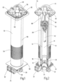
- the filter device is shown as a whole.
- the filter device has a filter housing 10 in which two filter elements 12, 14 are each arranged between a non-filtrate space 16, 18 and a common filtrate space 20.
- the two unfiltrate spaces 16, 18 are fluidly separated from one another, each unfiltrate space 16, 18 having its own inlet 22, 24 for unfiltrate, which is fluidly separated from the inlet 24, 22 of the other unfiltrate space 18, 16.
- the respective inlet 22, 24 is arranged in a common housing part 26 of the filter housing 10, the respective inlet 22, 24 having associated connection points 28, 30, 32, 34 in the housing part 26.
- the two filter elements 12, 14 are arranged coaxially one behind the other and the respective unfiltrate stream flows through them from the inside to the outside, with the unfiltrate cleaned in this way flowing out as filtrate into the common filtrate space 20.
- the unfiltrate space 16 of one filter element 12 runs between a closed, annular lateral surface 36 and a hollow cylindrical filter material of this one Filter element 12.
- the unfiltrate space 16 is connected on the bottom side to the inlet 22 for a leakage oil flow of a hydraulic unit, such as a hydraulic pump (not shown), the unfiltrate space 16 opening into an associated receiving space 40 in the housing part 26 via an axial connection point 38, which is separated from a further receiving space 42 in the housing part 26, into which the inlet 24 for a main oil flow opens, which is formed, for example, from the delivery flow of the hydraulic unit in the form of the pump, which internally generates the leakage oil flow mentioned as part of the pumping or delivery operation.
- a hydraulic unit such as a hydraulic pump (not shown)
- the unfiltrate space 16 opening into an associated receiving space 40 in the housing part 26 via an axial connection point 38, which is separated from a further receiving space 42 in the housing part 26, into which the inlet 24 for a main oil flow opens, which
- the inlet 24 for the main oil flow has a bottom-side connection point 30 in the housing part 26, which is arranged coaxially to the filter elements 12, 14 and can be controlled by a poppet valve 48, which is in the Fig. 3 is shown in its closed position and is also part of the lower end cap 44.
- the lower housing part 26 has two further connection points 32, 34 for the main oil flow, which, like the connection point 28 for the leakage oil flow, extend radially through the housing part 26.
- the plate valve 48 opens by its elastically flexible valve plate lifting off the valve seat.
- the poppet valve 48 closes and prevents the unwanted backflow of unfiltrate from the unfiltrate space 18 towards the further receiving space 42.
- the housing part 26 is designed in the manner of a half-shell and passes through in the direction of view Fig. 3 Seen from below, a tank wall 50 of a fluid storage tank, not shown.
- the housing part 26 is sealed from the underside of the tank wall 50 via an O-ring seal 52.
- four screw connections 54 serve to secure the housing part 26 to the tank wall 50.
- the actual filter housing 10 is formed from a type of cylindrical outflow pipe 56, which is provided with passage points 58 in the manner of a perforation, the passage points 58 forming the outflow pipe 56 reach through and establish a fluid-carrying connection between the filtrate space 20 and the interior of the storage tank, not shown.
- the passage points 58 serve to degas the filtered fluid as long as it is in the filtrate space 20 and the perforation or the passage points 58 extend on the circumference in the cylindrical outflow pipe 56 in an area above the one filter element 12 and below the center of the second filter element 14 in the direction of view the Fig. 1 to 3 seen.
- the filter material of the respective filter element 12, 14 is surrounded by a fluid-permeable support tube 60, 62, in which Fig. 6
- a section of the respective perforation 64 is shown as passage points for the respective support tube 60, 62.
- the respective element material of the filter element 12, 14 is accommodated between end caps 44, 46 and 48, the filter elements 12, 14 having a common end cap 66 on their mutually adjacent end faces, which is cylindrically widened on the outside and inside and at least partially in each case adjacent support tube 60, 62 overlaps on the outer circumference and on the inner circumference the adjacent element material of the filter element 14 together with the inner circumferential side of the cylindrical lateral surface 36.
- the lower end cap 44 has a first sealing means 70 on the outer circumference, which includes the support tube 60 of the filter element 12 and to this extent seals the element assembly with the filter elements 12, 14 against the inner wall of the housing part 26 in this area.
- the lower end cap 44 further has a downwardly projecting projection, which is provided with a further annular sealing means 72, which in turn seals the further receiving space 42 together with the unfiltrate space 18 with the poppet valve 48 open from the receiving space 40 for the inflow of the leakage oil flow .
- first sealing means 70 and the second sealing means 72 are arranged concentrically to one another, with the first sealing means 70 having a larger outer diameter than the second sealing means 72, which engages in a reduced diameter housing shoulder of the housing part 26 in the axial direction.
- the housing part 26 has a contact surface 74 for the contact of the lower end region of the outflow pipe 56.
- the middle end cap 66 delimits an annular passage opening 76, which provides a fluid connection between the further receiving space 52 and the unfiltrate space 18 of the filter element 14 when the poppet valve is open 48 allows.
- the filter device has a cover part 78, which is accommodated in a flange-like widening 80, which is fixed by means of a screw connection 82 to an upper tank wall, not shown, of the fluid storage tank.
- the cover part 78 can be pulled out of the flange-like widening 80 using an associated pivoting handle 84.
- the two sealants 70 come here, 72 at the lower end of the element assembly disengages from the adjacent housing wall parts of the housing part 26 remaining on the tank. The element assembly is removed in particular when the filter elements 12, 14 are used up due to particle contamination and have to be replaced with new elements.
- the insertion process then takes place in the reverse order and the two sealing means 70, 72 come into contact again in their concentric arrangement with the housing part 26 remaining on the tank.
- the filter device is then in the frame so-called in-tank solution for renewed filtration processes for a main oil and a leakage oil flow from a connected hydraulic unit, such as a pump.
- a bypass valve 90 on the underside of the cover part 78 via a web-like extension in engagement with the element assembly, the valve plate of which is held in a spring-loaded manner in a closed position when the filter element 14 is blocked and opens and a fluid connection between the unfiltrate space 18 and the filtrate space 20 on the inside of the Outflow pipe 56 produces.
- a magnetic device in the form of a rod-shaped permanent magnet 92 is arranged on the rod-like extension of the cover part 78, which is able to additionally clean metal particles from the fluid flow before they can reach the filter element 14.
- the filter device solution according to the invention a filter concept is realized with the possibility of cleaning a main flow and cleaning a leakage oil flow, whereby both fluid flows can come from one and the same hydraulic unit or from different units. Since the amount of leakage oil is less than the main flow amount, the leakage oil filter element 12 can be designed correspondingly smaller than the main flow filter element 14. Furthermore, this is the case Lower housing part 26 of the filter housing 10 serves as a type of collector, into which all connection points 28, 30, 32, 34 for the respective inlet 22, 24 open at a central location. This significantly simplifies the fluid flow during operation of the filter device. Furthermore, the filter device according to the invention can also be used to solve other filtration tasks that require main oil flow and secondary oil flow filtration. In addition to filtering oil, other fluids can also be treated.
- a tubular flow guide 94 is fitted on the inside, which ends with its free upper end in a receptacle 96 for the poppet valve 48 and with its other lower end in a shoulder-like recess in the lower housing part 26 .
- the poppet valve 48 can also be omitted, so that there is then a direct flow from the inside of the tube 94 to the inside of the filter element 14.
- the receptacle 96 which is penetrated by fluid passages (not shown) which are covered by the poppet valve 48, extends over the free edge of the insert sleeve 94 with an outer peripheral edge.
- the two outer peripheral surfaces of the filter elements 12 and 14 open into a common vertical peripheral surface and only the lower filter element 12 is set back on its inner peripheral side relative to the upper filter element 14 in order to increase the volume of the first unfiltrate space 16.
- the tube 94 forms the lateral surface 36 according to the embodiment Fig. 3 out of.
- at least one axial connection point 38 is provided, which in the present case is formed as a cylindrical round recess and surrounds the tube 94 at a radial distance.
- the first unfiltrate space 16 is fluidly connected to the first receiving space 40 and therefore to the first inlet 22 via the relevant annular connection point 38.
- the pipe 94 is in a concentric arrangement in a fluid-conducting connection with the second inlet 24, which opens into the second receiving space 42.
- the middle cap 66 is according to the exemplary embodiment Fig. 7 formed from two parts 98, 100, which can be releasably clipped together on the mirror side along their outer circumference via a latching connection 102 with a latching lug and a latching recess and, for sealing purposes, accommodate an O-shaped sealing ring 104 in the middle, which carries out the sealing in a common individual sealing plane .
- the two parts 98, 100 are equipped with a correspondingly suitable receptacle for the receptacle 96 of the poppet valve 48.
- the annular end cap part 98 is also used for the lower end cap 44, which forms the axial connection point 38 on the inner circumference and has a groove-shaped receptacle for a further annular seal 106 on the outer circumference, which, in cooperation with the lower lower housing part 26, ensures the seal between the filtrate space 20 and the first receiving space 40 of the inlet 22 produces, comparable to the seal 70 in the exemplary embodiment according to the Fig. 3 .
- the modified embodiment according to the Fig. 7 The same advantages can be achieved as described above; If necessary, the relevant embodiment alone can be implemented more cost-effectively with fewer components using identical components, in particular regarding the end caps 44 and 66.
Description
Die Erfindung betrifft eine Filtervorrichtung mit den Merkmalen im Oberbegriff von Anspruch 1.The invention relates to a filter device with the features in the preamble of claim 1.
Durch
Die
Weitere Filtervorrichtungen gehen aus der
Ausgehend von diesem Stand der Technik liegt der Erfindung die Aufgabe zugrunde, unter Beibehalten der Vorteile der bekannten Filtervorrichtung eine demgegenüber verbesserte Lösung zu schaffen mit vermehrten Einsatzmögl ichkeiten.Based on this prior art, the invention is based on the object of creating an improved solution with increased possible uses while maintaining the advantages of the known filter device.
Eine dahingehende Aufgabe löst eine Filtervorrichtung mit den Merkmalen des Patentanspruches 1 in seiner Gesamtheit.A filter device with the features of patent claim 1 solves this problem in its entirety.
Gemäß dem Kennzeichen von Anspruch 1 ist vorgesehen, dass das Filtergehäuse aus einer Art Abströmrohr gebildet ist mit Durchlassstellen, die der Strömungsführung des gefilterten Fluids dienen und durch welche eine fluidführende Verbindung zwischen dem Filtratraum und einem Inneren eines Tanks herstellbar ist, in den die Filtervorrichtung aufnehmbar ist.According to the characterizing part of claim 1, it is provided that the filter housing is formed from a type of outflow pipe with passage points which serve to guide the flow of the filtered fluid and through which a fluid-carrying connection can be established between the filtrate space and an interior of a tank into which the filter device can be accommodated is.
Im Hydrauliköl kann grundsätzlich Luft, auch in feindispergierter Form, mitgeführt sein und die Luft scheidet sich an den genannten Durchlassstellen aus dem Fluid ab unter Bildung größerer Blasen, die ab einer gewissen Auftriebsgröße aus dem Fluid nach oben hin in einen Tank austreten. Dergestalt ist ein Entgasen des Betriebsfluids in Form des Hauptöls und gleichzeitig des Lecköls möglich.In principle, air can be carried in the hydraulic oil, even in finely dispersed form, and the air separates at the passage points mentioned from the fluid to form larger bubbles, which emerge from the fluid upwards into a tank when the buoyancy reaches a certain level. In this way, degassing of the operating fluid in the form of the main oil and the leakage oil is possible at the same time.
Dadurch, dass die Unfiltraträume fluidisch voneinander getrennt sind und jeder Unfiltratraum einen eigenen Zulauf für Unfiltrat aufweist, der von dem Zulauf des jeweils anderen Unfiltratraums fluidisch getrennt ist, ist ein Filterelementverbund mit zwei Filterelementen in einem Filtergehäuse geschaffen, das zwei voneinander getrennte Unfiltraträume aufweist, von denen jeweils ein Unfiltratstrom ausgehend, von dem zugehörigen Filterelement von Partikelverschmutzung abgereinigt, in einen gemeinsamen Filtratraum eintritt. Die beiden Filterelemente können als eigenständige Bauteile benachbart zueinander angeordnet und beispielsweise mittels einer Endkappe voneinander separiert miteinander verbunden sein; es besteht aber auch die Möglichkeit, mittels einer Clipverbindung diese lösbar aneinanderzulegen oder über eine Schweiß- oder Klebstoffverbindung diese direkt an ihren einander benachbarten Enden miteinander fest zu verbinden.Because the unfiltrate spaces are fluidly separated from one another and each unfiltrate space has its own inlet for unfiltrate, which is fluidly separated from the inlet of the other unfiltrate space, a filter element composite with two filter elements is created in a filter housing which has two separate unfiltrate spaces each of which a stream of unfiltrate, cleaned of particle contamination by the associated filter element, enters a common filtrate space. The two filter elements can be arranged adjacent to one another as independent components and connected to one another separately from one another, for example by means of an end cap; However, it is also possible to releasably place them together using a clip connection or to connect them directly to one another at their adjacent ends using a weld or adhesive connection.
Dergestalt ist eine Möglichkeit geschaffen, sowohl einen von einer hydraulischen Einheit, wie beispielsweise einer hydraulischen Pumpe, stammenden Hauptölstrom abzureinigen einschließlich eines zusätzlichen Leckölstromes, der gleichfalls von dieser hydraulischen Einheit stammt und der in Verbindung mit dem Fördern oder Ansteuern des Hauptvolumenstromes im Betrieb der Einheit respektive der Pumpe zwangsläufig mit entsteht. Durch die Aufteilung des Filterelementverbundes innerhalb der Filtervorrichtung in zwei Behandlungsbereiche für voneinander getrennt geführte Fluidströme, lässt sich mit dem einen Behandlungsbereich der Hauptölstrom als Hauptstrom filtrieren und mit dem anderen Behandlungsbereich der Leckölstrom als eigentlicher Nebenstrom.In this way, a possibility is created to clean both a main oil flow coming from a hydraulic unit, such as a hydraulic pump, including an additional leakage oil flow, which also comes from this hydraulic unit and which is in connection with the delivery or control of the main volume flow during operation of the unit or the pump inevitably arises. By dividing the filter element assembly within the filter device into two treatment areas for fluid streams that are conducted separately from one another, the main oil flow can be filtered as the main flow with one treatment area and the leakage oil flow can be filtered as the actual secondary flow with the other treatment area.
Bei einer bevorzugten Ausführungsform der erfindungsgemäßen Filtervorrichtung ist vorgesehen, dass der jeweilige Zulauf in einem gemeinsamen Gehäuseteil des Filtergehäuses angeordnet ist, und dass der jeweilige Zulauf mindestens eine Anschlussstelle im Gehäuseteil aufweist. Insbesondere für die Zufuhr des Hauptölstromes weist im Hinblick auf die damit verbundene große Fluidmenge der zuordenbare Zulauf mehrere Anschlussstellen im Gehäuseteil auf, die mit der hydraulischen Einheit über übliche Fluidleitungen in Verbindung stehen. Über die voneinander getrennten Zuflüsse nebst ihrer getrennten Fluidführung im Gehäuseteil ist dergestalt auch eine wärmetechnische Entkopplung von Haupt- und Nebenstrom erreicht, so dass es zu einer vergleichmäßigten Wärmeeinleitung in das sonstige Gehäuse kommt.In a preferred embodiment of the filter device according to the invention, it is provided that the respective inlet is arranged in a common housing part of the filter housing, and that the respective inlet has at least one connection point in the housing part. In particular, for the supply of the main oil flow, in view of the large amount of fluid associated with it, the assignable inlet has several connection points in the housing part, which are connected to the hydraulic unit via conventional fluid lines. A thermal decoupling of the main and secondary flow is achieved via the separate inflows and their separate fluid flow in the housing part, so that there is a uniform introduction of heat into the rest of the housing.
Bei einer weiteren bevorzugten Ausführungsform der erfindungsgemäßen Filtervorrichtung ist vorgesehen, dass die beiden Filterelemente koaxial hintereinander angeordnet von innen nach außen durchströmt einen gemeinsamen Filtratraum aufweisen. Die insoweit einen Filterelementverbund bildenden beiden Filterelemente lassen sich dergestalt platzsparend im Filtergehäuse unterbringen, wobei das Filterelement für den Hauptstrom mit der größeren Fluidmenge deutlich größer, insbesondere länger, konzipiert sein kann als das Filterelement für den Lecköl- oder Nebenstrom. Über den gemeinsamen Filtratraum gelangt das Filtrat strömungstechnisch günstig aus dem genannten Filterelementverbund in einen Vorratstank.In a further preferred embodiment of the filter device according to the invention it is provided that the two filter elements arranged coaxially one behind the other have a common filtrate space through which flows from the inside to the outside. The two filter elements forming a filter element composite can be accommodated in the filter housing in a space-saving manner, whereby the filter element for the main flow with the larger amount of fluid can be designed to be significantly larger, in particular longer, than the filter element for the leakage oil or secondary flow. The filtrate flows favorably from the aforementioned filter element assembly into a storage tank via the common filtrate space.
Bei einer weiteren bevorzugten Ausführungsform der erfindungsgemäßen Filtervorrichtung ist vorgesehen, dass der Unfiltratraum des einen Filterelementes zwischen einer geschlossenen Mantelfläche und einem Filtermaterial dieses Filterelementes verläuft, der bodenseitig an einen Zulauf für einen Leckölstrom angeschlossen ist, der mit seiner axialen Anschlussstelle in einen Aufnahmeraum im Gehäuseteil ausmündet, der von einem weiteren Aufnahmeraum im Gehäuseteil abgetrennt ist, in das der Zulauf für einen Hauptölstrom einmündet. Die Filtervorrichtung wird insbesondere als sogenannte In-Tank-Lösung eingesetzt mit vertikaler Betriebsstellung, so dass sich die Angabe bodenseitig auf den unteren Fluidbereich der Filtervorrichtung bezieht. Aufgrund der konzentrischen Anordnung zwischen geschlossener Mantelfläche und hohlzylindrischem Filtermaterial entsteht ein gleichförmiger Ringraum als Unfiltratraum, der von der Bodenseite her befüllt, eine gleichmäßige Fluidverteilung im zuordenbaren Unfiltratraum erlaubt mit gleichmäßiger Durchströmung des genannten Filterelementes von innen nach außen.In a further preferred embodiment of the filter device according to the invention it is provided that the unfiltrate space of one filter element runs between a closed lateral surface and a filter material of this filter element, which is connected on the bottom side to an inlet for a leakage oil flow, which opens with its axial connection point into a receiving space in the housing part , which is separated from another receiving space in the housing part, into which the inlet for a main oil flow flows. The filter device is particularly referred to as a so-called In-tank solution used with a vertical operating position, so that the information on the bottom refers to the lower fluid area of the filter device. Due to the concentric arrangement between the closed lateral surface and the hollow cylindrical filter material, a uniform annular space is created as an unfiltrate space, which is filled from the bottom side, allowing a uniform distribution of fluid in the assignable unfiltrate space with a uniform flow through the said filter element from the inside to the outside.
Bei einer weiteren bevorzugten Ausführungsform der erfindungsgemäßen Filtervorrichtung ist vorgesehen, dass der Zulauf für den Hauptölstrom eine bodenseitige Anschlussstelle im Gehäuseteil aufweist, die koaxial zu den Filterelementen angeordnet ist, und dass mindestens eine weitere Anschlussstelle für den Hauptölstrom vorhanden ist, die wie die Anschlussstelle für den Leckölstrom radial das Gehäuseteil durchgreift. Durch die Anordnung der Anschlussstellen sowohl in axialer Richtung als auch in quer dazu verlaufender Radialrichtung im Gehäuseteil lässt sich in bauraumsparender Weise eine Vielzahl von Zuflussmöglichkeiten für den jeweiligen Unfiltratstrom erreichen, sowohl bezogen auf den Hauptstrom als auch auf den Nebenstrom. Das in Fluidströmungsrichtung des Unfiltratstromes für das Hauptfilterelement aufsteuernde Tellerventil verhindert bei Außerbetriebnahme ein ungewolltes Rückströmen des Unfiltrats vom Innern dieses Filterelementes auf die Zulaufseite.In a further preferred embodiment of the filter device according to the invention it is provided that the inlet for the main oil flow has a bottom-side connection point in the housing part, which is arranged coaxially to the filter elements, and that at least one further connection point for the main oil flow is present, which is like the connection point for the Leakage oil flow penetrates radially through the housing part. By arranging the connection points both in the axial direction and in the radial direction running transversely thereto in the housing part, a large number of inflow options for the respective unfiltrate stream can be achieved in a space-saving manner, both in relation to the main stream and to the secondary stream. The poppet valve, which opens in the fluid flow direction of the unfiltrate flow for the main filter element, prevents unwanted backflow of the unfiltrate from the inside of this filter element to the inlet side when it is decommissioned.
Besonders bevorzugt ist vorgesehen, dass die beiden Filterelemente, insbesondere nach deren Verbrauch, nach Entfernen eines Deckelteils vom Filtergehäuse aus diesem im Rahmen eines Elementverbundes entnehmbar und gegen Neu-Filterelemente tauschbar sind. Dergestalt lässt sich zeitnah und auf einfache Weise mit geringen Betätigungskräften ein Elementwechsel vornehmen.Particularly preferably, it is provided that the two filter elements, in particular after they have been used up, can be removed from the filter housing after a cover part has been removed from the filter housing as part of an element assembly and exchanged for new filter elements. In this way, an element change can be carried out quickly and easily with low actuation forces.
Bei einer weiteren bevorzugten Ausführungsform der erfindungsgemäßen Filtervorrichtung ist vorgesehen, dass das Filtermaterial des jeweiligen Filterelementes von einem fluiddurchlässigen Stützrohr umgeben ist und stirnseitig von mindestens einer Endkappe eingefasst ist. Dergestalt kann sich das plissierte, mehrlagige Filtermaterial am Stützrohr abstützen, um die Filterfunktion zu gewährleisten. Zwischen dem jeweiligen Stützrohr und dem rohrförmigen Filtergehäuse besteht ein vorgebbarer radialer Abstand, der den Filtratraum ausbildet, indem das jeweils abgereinigte Unfiltrat aus dem Elementverbund abgeführt werden kann. In diesem Filtratraum kommt es zu einer Vergleichmäßigung der Filtratströmung nebst deren Beruhigung mit der Möglichkeit der Gasblasenabscheidung aus dem Betriebsfluid.In a further preferred embodiment of the filter device according to the invention it is provided that the filter material of the respective filter element is surrounded by a fluid-permeable support tube and is bordered on the front side by at least one end cap. In this way, the pleated, multi-layer filter material can be supported on the support tube to ensure the filter function. There is a predeterminable radial distance between the respective support tube and the tubular filter housing, which forms the filtrate space in which the cleaned unfiltrate can be removed from the element assembly. In this filtrate space, the filtrate flow is evened out and calmed down with the possibility of gas bubbles being separated from the operating fluid.
Bei einer weiteren bevorzugten Ausführungsform der erfindungsgemäßen Filtervorrichtung ist vorgesehen, dass die bodenseitige Endkappe des einen Filterelementes für den Hauptölstrom in mindestens einer Ebene mindestens ein einzelnes Dichtmittel aufweist zwecks Abdichten des Elementverbundes gegenüber dem Gehäuseteil bei gleichzeitigem Trennen des jeweiligen Unfiltratraums vom Filtratraum. Dergestalt wird der Elementverbund bei einem Austausch gegen Neu-Filterelemente zusammen mit den Dichtmitteln aus dem Filtergehäuse händisch entfernt, was einem vereinfachten Austausch zugutekommt.In a further preferred embodiment of the filter device according to the invention it is provided that the bottom end cap of the one filter element for the main oil flow has at least one individual sealant in at least one level for the purpose of sealing the element assembly from the housing part while simultaneously separating the respective unfiltrate space from the filtrate space. In this way, when replacing new filter elements with new filter elements, the element assembly is removed manually from the filter housing together with the sealants, which facilitates easier replacement.
Bei einer weiteren bevorzugten Ausführungsform der erfindungsgemäßen Filtervorrichtung ist vorgesehen, dass das Deckelteil ein Bypassventil und/ oder eine Magneteinrichtung, insbesondere in Form eines stabförmigen Permanentmagneten, aufweist. Ist insbesondere der Hauptölfilter von Partikelverschmutzung zugesetzt, erlaubt das Bypassventil unter Umgehung des verschmutzten Filterelementes eine Abfuhr des Filtratstroms in Richtung der Filtratseite der Vorrichtung. Mittels der Magneteinrichtung lassen sich etwaige metallische Partikel aus dem Unfiltratstrom absondern, die sich dann an der Magneteinrichtung respektive an dem stabförmigen Permanentmagneten ablagern.In a further preferred embodiment of the filter device according to the invention it is provided that the cover part has a bypass valve and/or a magnetic device, in particular in the form of a rod-shaped permanent magnet. In particular, if the main oil filter is clogged with particle contamination, the bypass valve allows the filtrate flow to be discharged towards the filtrate side of the device, bypassing the dirty filter element. By means of the magnet device, any metallic particles can be separated from the unfiltrate stream, which are then deposited on the magnet device or on the rod-shaped permanent magnet.
Die Erfindung betrifft des Weiteren eine Filtervorrichtung mit einem Filterelementverbund bestehend aus zwei Filterelementen, die über eine gemeinsame Endkappe miteinander verbunden sind, wobei sich ein Filtermaterial des einen Filterelementes unter Bildung eines Aufnahmeraumes um einen geschlossenen Mantel erstreckt und wobei dieser Aufnahmeraum über Durchlassstellen in einer weiteren Endkappe des einen Filterelementes in die Umgebung ausmündet. Dergestalt bilden die Durchlassstellen eine Zulaufmöglichkeit für Unfiltrat in den einen Aufnahmeraum als Unfiltratraum und die geschlossene Mantelfläche erlaubt eine gezielte Fluidführung aus diesem Unfiltratraum in Richtung der Filtratseite der Vorrichtung.The invention further relates to a filter device with a filter element composite consisting of two filter elements which are connected to one another via a common end cap, a filter material of one filter element extending around a closed jacket to form a receiving space and this receiving space having passage points in a further end cap one filter element opens into the environment. In this way, the passage points form an inlet possibility for unfiltrate into the one receiving space as an unfiltrate space and the closed lateral surface allows targeted fluid flow from this unfiltrate space in the direction of the filtrate side of the device.
Bei einer weiteren besonders bevorzugten Ausführungsform ist vorgesehen, dass in einem bodenseitigen Bereich des Filterelementes mit dem geschlossenen Mantel zwei voneinander verschiedene Dichtmittel mit außenumfangsseitiger Dichtwirkung derart angeordnet sind, dass die zugehörigen Dichtringe zueinander konzentrisch verlaufen. Soweit dieser Filterelementverbund gegen Neuelemente getauscht wird, werden auch die zugehörigen Dichtmittel mit ausgetauscht und die Dichtmittel bilden insoweit eine Führung aus für das gezielte Einsetzen des Filterelementverbundes in den unteren Bodenbereich durch Einschieben in das sich anschließende Gehäuseteil, das im Wesentlichen unterhalb einer Bodentankwand des Fluidtanks angeordnet ist.In a further particularly preferred embodiment it is provided that two different sealing means with an outer circumferential sealing effect are arranged in a bottom area of the filter element with the closed jacket in such a way that the associated sealing rings run concentrically to one another. If this filter element assembly is exchanged for new elements, the associated sealing means are also replaced and the sealing means form a guide for the targeted insertion of the filter element assembly into the lower base area by inserting it into the adjoining housing part, which is arranged essentially below a bottom tank wall of the fluid tank is.
Im Folgenden wird die erfindungsgemäße Filtervorrichtung nebst Filterelementverbund anhand von Ausführungsformen nach der Zeichnung näher erläutert. Dabei zeigen in prinzipieller und nicht maßstäblicher Darstellung die
- Fig. 1
- in perspektivischer Ansicht die wesentlichen Teile der Filter-vorrichtung als Ganzes;
- Fig. 2
- eine der
Fig. 1 entsprechende Darstellung im Teillängsschnitt; - Fig. 3
- in der Art eines Längsschnittes den unteren Bereich der Filtervorrichtung nach den
Fig. 1 und 2 ; - Fig. 4
- eine Unteransicht auf die Vorrichtungsteile nach der
Fig. 3 ; - Fig. 5 und 6
- im teilgeschnittenen Zustand bzw. in Ansicht einen Filterelementverbund, wie er bei der Lösung nach den
Fig. 1 bis 4 Verwendung findet; und - Fig. 7
- eine der
Fig. 3 entsprechende Darstellung einer geänderten Ausführungsform.
- Fig. 1
- in perspective view the essential parts of the filter device as a whole;
- Fig. 2
- one of the
Fig. 1 corresponding representation in partial longitudinal section; - Fig. 3
- in the manner of a longitudinal section the lower area of the filter device
Fig. 1 and 2 ; - Fig. 4
- a bottom view of the device parts after
Fig. 3 ; - 5 and 6
- in the partially cut state or in view of a filter element composite, as in the solution according to the
Fig. 1 to 4 is used; and - Fig. 7
- one of the
Fig. 3 corresponding representation of a modified embodiment.
In den
Der jeweilige Zulauf 22, 24 ist in einem gemeinsamen Gehäuseteil 26 des Filtergehäuses 10 angeordnet, wobei der jeweilige Zulauf 22, 24 zugeordnete Anschlussstellen 28, 30, 32, 34 im Gehäuseteil 26 aufweist. Die beiden Filterelemente 12, 14 sind koaxial hintereinander angeordnet und werden von dem jeweiligen Unfiltratstrom von innen nach außen durchströmt, wobei das derart abgereinigte Unfiltrat als Filtrat in den gemeinsamen Filtratraum 20 ausströmt.The
Wie sich insbesondere aus der
Sowohl das Filtermaterial des Filterelementes 12 als auch die hohlzylindrische Mantelfläche 36 münden in Blickrichtung auf die
Neben der bodenseitigen, axialen Anschlussstelle 38 weist das untere Gehäuseteil 26 zwei weitere Anschlussstellen 32, 34 für den Hauptölstrom auf, die wie die Anschlussstelle 28 für den Leckölstrom radial das Gehäuseteil 26 durchgreifen. Sobald über den Zulauf 24 der Hauptölstrom mit vorgebbarem Druck in den weiteren Aufnahmeraum 42 im Gehäuseteil 26 einströmt, öffnet das Tellerventil 48, indem sein elastisch nachgiebiger Ventilteller vom Ventilsitz abhebt. Bei stillgesetzter Filtervorrichtung schließt das Tellerventil 48 und verhindert das ungewollte Rückströmen von Unfiltrat aus dem Unfiltratraum 18 in Richtung des weiteren Aufnahmeraumes 42.In addition to the bottom-side,
Das Gehäuseteil 26 ist in der Art einer Halbschale ausgebildet und durchgreift in Blickrichtung auf die
Wie sich insbesondere aus den
Die untere Endkappe 44 weist außenumfangsseitig ein erstes Dichtmittel 70 auf, das das Stützrohr 60 des Filterelementes 12 umfasst und insoweit den Elementverbund mit den Filterelementen 12, 14 gegenüber der Innenwand des Gehäuseteiles 26 in diesem Bereich abdichtet. Wie insbesondere die
Das Gehäuseteil 26 weist nach oben hin gesehen eine Anlagefläche 74 auf für die Anlage des unteren Endbereiches des Abströmrohres 56. Die mittlere Endkappe 66 begrenzt eine ringförmige Durchlassöffnung 76, die eine Fluidverbindung zwischen dem weiteren Aufnahmeraum 52 und dem Unfiltratraum 18 des Filterelementes 14 bei geöffnetem Tellerventil 48 ermöglicht. Wie sich insbesondere aus der
Nach Lösen der Schraubverbindung 82 kann das Deckelteil 78 über einen zugeordneten schwenkbaren Handgriff 84 aus der flanschartigen Verbreiterung 80 herausgezogen werden. Damit ist eine Entnahmeöffnung 86 im oberen Bereich des Filtergehäuses 10 respektive des Abströmrohres 56 freigegeben und der Elementverbund, bestehend aus den beiden Filterelementen 12, 14, kann mittels eines Bügelgriffes 88 aus dem Abströmrohr 56 von Hand herausgezogen werden. Dabei kommen die beiden Dichtmittel 70, 72 am unteren Ende des Elementverbundes außer Eingriff mit den benachbarten Gehäusewandteilen des insoweit am Tank verbleibenden Gehäuseteils 26. Eine dahingehende Entnahme des Elementverbundes findet insbesondere dann statt, wenn die Filterelemente 12, 14 wegen Partikelverschmutzung verbraucht sind und gegen Neuelemente getauscht werden müssen. Der Einsatzvorgang findet dann in umgekehrter Reihenfolge statt und die beiden Dichtmittel 70, 72 kommen in ihrer konzentrischen Anordnung wieder in Anlage mit dem am Tank verbleibenden Gehäuseteil 26. Nach Aufsetzen des Deckelteils 78 und erneutem Herstellen der Schraubverbindung 82, steht dann die Filtervorrichtung im Rahmen einer sogenannten In-Tank-Lösung für erneute Filtrationsvorgänge für einen Hauptöl- und einen Leckölstrom einer angeschlossenen hydraulischen Einheit, wie einer Pumpe, zur Verfügung.After loosening the
Wie sich des Weiteren aus der
Mit der erfindungsgemäßen Filtervorrichtungslösung ist ein Filterkonzept realisiert mit der Möglichkeit des Abreinigens eines Hauptstromes und dem Abreinigen eines Leckölstroms, wobei beide Fluidströme von ein und derselben hydraulischen Einheit stammen können oder eben auch von verschiedenen Einheiten. Da die Leckölmenge geringer ist als die Hauptstrommenge kann das Leckölfilterelement 12 entsprechend kleiner konzipiert sein als das Hauptstromfilterelement 14. Des Weiteren kommt dem unteren Gehäuseteil 26 des Filtergehäuses 10 die Aufgabe eines Art Sammlers zu, in den alle Anschlussstellen 28, 30, 32, 34 für den jeweiligen Zulauf 22, 24 an zentraler Stelle einmünden. Dies vereinfacht die Fluidstromführung im Betrieb der Filtervorrichtung deutlich. Des Weiteren lassen sich mit der erfindungsgemäßen Filtervorrichtung auch andere Filtrationsaufgaben lösen, die einer Hauptölstrom- und einer Nebenölstromfiltration bedürfen. Neben der Filtration von Öl können auch andere Fluide behandelt werden.With the filter device solution according to the invention, a filter concept is realized with the possibility of cleaning a main flow and cleaning a leakage oil flow, whereby both fluid flows can come from one and the same hydraulic unit or from different units. Since the amount of leakage oil is less than the main flow amount, the leakage
Im Folgenden wird die geänderte Ausführungsform nach der
Ferner münden die beiden Außenumfangsflächen der Filterelemente 12 und 14 in eine gemeinsame vertikale Umfangsfläche aus und nur das untere Filterelement 12 ist auf seiner Innenumfangsseite gegenüber dem oberen Filterelement 14 zurückversetzt zwecks Vergrößern des Volumens des ersten Unfiltratraums 16. Insoweit bildet das Rohr 94 die Mantelfläche 36 nach der Ausführungsform gemäß
Die mittlere Kappe 66 ist gemäß dem Ausführungsbeispiel nach der
Claims (11)
- Filter device with a filter housing (10), in which at least two filter elements (12, 14) are arranged between an unfiltered medium chamber (16, 18) and a filtrate chamber (20) in each case, the unfiltered medium chambers (16, 18) being fluidically separated from one another and each unfiltered medium chamber (16, 18) having its own inlet (22, 24) for unfiltered medium, which is fluidically separate from the inlet (22, 24) to the respective other unfiltered medium chamber (16, 18), characterised in that the filter housing (10) is formed by a kind of discharge pipe (56) with passage points (58), which serve to guide the flow of filtered fluid and by means of which a fluid-conveying connection can be established between the filtrate chamber (20) and an interior of a tank, in which the filter device can be received.
- Filter device according to claim 1, characterised in that the respective inlet (22, 24) is arranged in a common housing part (26) of the filter housing (10), and in that the respective inlet (22, 24) comprises at least one connection point (28, 30, 32, 34) in the housing part (26).
- Filter device according to either claim 1 or claim 2, characterised in that the two filter elements (12, 14), arranged coaxially behind one another, with the throughflow passing from the inside to the outside, comprise a common filtrate chamber (20).
- Filter device according to either claim 2 or claim 3, characterised in that the unfiltered medium chamber (16) of one filter element (12) runs between a closed jacket surface (36) and a filter material of this filter element (12), which is connected at its bottom side to an inlet (22) for a leakage oil flow, which, with its axial connection point (38), emerges into a receiving chamber (40) in the housing part (26), which is separate from a further receiving chamber (42) in the housing part (26), into which the inlet (24) for a main oil flow discharges.
- Filter device according to any of claims 2 to 4, characterised in that the inlet (24) for the main oil flow has a bottom connection point (30) in the housing part (26), which is arranged coaxially with respect to the filter elements (12, 14), and in that at least one further connection point (32, 34) is provided for the main oil flow, which, like the connection point (28) for the leakage oil flow, passes radially through the housing part (26).
- Filter device according to any of the preceding claims, characterised in that the two filter elements (12, 14), particularly after they have been used, can be taken out of the filter housing (10) in the composite element after removing a lid part (78) of said filter housing (10), and replaced with new filter elements.
- Filter device according to any of the preceding claims, characterised in that the filter material of the respective filter element (12, 14) is surrounded by a fluid-permeable supporting tube (60, 62) and is bordered at its ends by at least one end cap (44, 66, 68).
- Filter device according to claim 7, characterised in that the bottom end cap (44) of the one filter element (12) for the main oil flow comprises at least one individual sealing means (70, 72) in at least one plane for the purpose of sealing the composite element from the housing part (26) while simultaneously separating the respective unfiltered medium chamber (16, 18) from the filtrate chamber (20).
- Filter device according to any of claims 6 to 8, characterised in that the lid part (78) comprises a bypass valve (90) and/or a magnet apparatus, particularly in the form of a rod-shaped permanent magnet (92).
- Filter device according to any of the preceding claims with a composite filter element consisting of two filter elements (12, 14), which are connected to one another via a common end cap (66), characterised in that a filter material of one filter element (12) extends around a closed jacket (36), forming a receiving chamber (40), and in that this receiving chamber (40) has passage points (38) in a further end cap (44) of said one filter element (12).
- Filter device according to claim 10, characterised in that two different sealing means (70, 72) with a sealing action are arranged in a bottom region of the filter element (12) with the closed jacket (36) such that the associated sealing rings run concentrically with respect to one another.
Applications Claiming Priority (1)
| Application Number | Priority Date | Filing Date | Title |
|---|---|---|---|
| DE102021003480.5A DE102021003480A1 (en) | 2021-07-06 | 2021-07-06 | filter device |
Publications (3)
| Publication Number | Publication Date |
|---|---|
| EP4115964A1 EP4115964A1 (en) | 2023-01-11 |
| EP4115964C0 EP4115964C0 (en) | 2024-02-14 |
| EP4115964B1 true EP4115964B1 (en) | 2024-02-14 |
Family
ID=82321534
Family Applications (1)
| Application Number | Title | Priority Date | Filing Date |
|---|---|---|---|
| EP22181375.1A Active EP4115964B1 (en) | 2021-07-06 | 2022-06-27 | Filter device |
Country Status (2)
| Country | Link |
|---|---|
| EP (1) | EP4115964B1 (en) |
| DE (1) | DE102021003480A1 (en) |
Family Cites Families (6)
| Publication number | Priority date | Publication date | Assignee | Title |
|---|---|---|---|---|
| US5766468A (en) * | 1997-01-06 | 1998-06-16 | Baldwin Filters, Inc. | Dual media primary/secondary fuel filter |
| DE19955635A1 (en) | 1999-11-20 | 2001-05-31 | Argo Gmbh Fuer Fluidtechnik | Filtering device, for filtering hydraulic fluids, comprises filter housing containing filter element with partial filter elements |
| DE10001259A1 (en) | 2000-01-14 | 2001-07-19 | Hydac Filtertechnik Gmbh | Filter includes two elements in casing, to retain particles of differing sizes and has passage connecting filter chambers |
| US20080179263A1 (en) * | 2006-07-31 | 2008-07-31 | Wieczorek Mark T | Combined filter apparatus, system, and method |
| DE102006036231A1 (en) * | 2006-08-03 | 2008-02-07 | Hydac Filtertechnik Gmbh | filter means |
| US9782702B2 (en) * | 2014-05-22 | 2017-10-10 | Pall Corporation | Filter assemblies, filter elements, and methods for filtering liquids |
-
2021
- 2021-07-06 DE DE102021003480.5A patent/DE102021003480A1/en active Pending
-
2022
- 2022-06-27 EP EP22181375.1A patent/EP4115964B1/en active Active
Also Published As
| Publication number | Publication date |
|---|---|
| EP4115964C0 (en) | 2024-02-14 |
| DE102021003480A1 (en) | 2023-01-12 |
| EP4115964A1 (en) | 2023-01-11 |
Similar Documents
| Publication | Publication Date | Title |
|---|---|---|
| EP3004620B1 (en) | Filter element | |
| EP2249941B1 (en) | Filter apparatus and filter element for such a filter apparatus | |
| DE60220407T2 (en) | REFILLABLE HYBRID FILTER | |
| DE10151864B4 (en) | Method for operating a filter for liquids and system for carrying out the method | |
| EP2207609A1 (en) | Filter device | |
| DE19955635A1 (en) | Filtering device, for filtering hydraulic fluids, comprises filter housing containing filter element with partial filter elements | |
| EP2448647B1 (en) | Filter device | |
| EP1926540B1 (en) | Filter device | |
| DE112007001880T5 (en) | Quick-drain filter | |
| DE102013012918C5 (en) | Liquid filter and filter element, in particular for fuel | |
| EP3265202B1 (en) | System for filtering fluids | |
| EP1996307A1 (en) | Filter insert having a closure for a second filter chamber | |
| EP1246680B1 (en) | Filter device | |
| EP0276795A2 (en) | Filtering device for polluted liquids | |
| EP2704812A1 (en) | Filtering apparatus | |
| DE102014000903A1 (en) | Filter and coalescing element and associated media layer and filter device | |
| DE202006004527U1 (en) | Automotive liquid filter has main outer housing containing two concentric discrete filter units | |
| DE202006004529U1 (en) | Filter insert for a motor vehicle's oil/fuel filter has an end plate and a filter medium to be fitted in a filter's filter chamber | |
| EP4115964B1 (en) | Filter device | |
| WO2018146102A1 (en) | Fuel filter comprising a filter insert with a prefilter element and a main filter element | |
| DE102013001843A1 (en) | Filter element for filtering e.g. urea, has hydrophilic and hydrophobic portions that are in fluid communication with outlets for taking out filtered liquid from filter element and for leading gas from filter element respectively | |
| DE3909382A1 (en) | FILTER ELEMENT | |
| DE102017000713A1 (en) | filter means | |
| WO2022233459A1 (en) | Filter device | |
| DE2948868A1 (en) | FILTER UNIT |
Legal Events
| Date | Code | Title | Description |
|---|---|---|---|
| PUAI | Public reference made under article 153(3) epc to a published international application that has entered the european phase |
Free format text: ORIGINAL CODE: 0009012 |
|
| STAA | Information on the status of an ep patent application or granted ep patent |
Free format text: STATUS: THE APPLICATION HAS BEEN PUBLISHED |
|
| AK | Designated contracting states |
Kind code of ref document: A1 Designated state(s): AL AT BE BG CH CY CZ DE DK EE ES FI FR GB GR HR HU IE IS IT LI LT LU LV MC MK MT NL NO PL PT RO RS SE SI SK SM TR |
|
| STAA | Information on the status of an ep patent application or granted ep patent |
Free format text: STATUS: REQUEST FOR EXAMINATION WAS MADE |
|
| 17P | Request for examination filed |
Effective date: 20230711 |
|
| RBV | Designated contracting states (corrected) |
Designated state(s): AL AT BE BG CH CY CZ DE DK EE ES FI FR GB GR HR HU IE IS IT LI LT LU LV MC MK MT NL NO PL PT RO RS SE SI SK SM TR |
|
| GRAP | Despatch of communication of intention to grant a patent |
Free format text: ORIGINAL CODE: EPIDOSNIGR1 |
|
| STAA | Information on the status of an ep patent application or granted ep patent |
Free format text: STATUS: GRANT OF PATENT IS INTENDED |
|
| INTG | Intention to grant announced |
Effective date: 20231010 |
|
| GRAS | Grant fee paid |
Free format text: ORIGINAL CODE: EPIDOSNIGR3 |
|
| GRAA | (expected) grant |
Free format text: ORIGINAL CODE: 0009210 |
|
| STAA | Information on the status of an ep patent application or granted ep patent |
Free format text: STATUS: THE PATENT HAS BEEN GRANTED |
|
| AK | Designated contracting states |
Kind code of ref document: B1 Designated state(s): AL AT BE BG CH CY CZ DE DK EE ES FI FR GB GR HR HU IE IS IT LI LT LU LV MC MK MT NL NO PL PT RO RS SE SI SK SM TR |
|
| REG | Reference to a national code |
Ref country code: GB Ref legal event code: FG4D Free format text: NOT ENGLISH |
|
| REG | Reference to a national code |
Ref country code: CH Ref legal event code: EP |
|
| REG | Reference to a national code |
Ref country code: DE Ref legal event code: R096 Ref document number: 502022000497 Country of ref document: DE |
|
| REG | Reference to a national code |
Ref country code: IE Ref legal event code: FG4D Free format text: LANGUAGE OF EP DOCUMENT: GERMAN |
|
| U01 | Request for unitary effect filed |
Effective date: 20240214 |
|
| U07 | Unitary effect registered |
Designated state(s): AT BE BG DE DK EE FI FR IT LT LU LV MT NL PT SE SI Effective date: 20240221 |