EP2249941B1 - Filter apparatus and filter element for such a filter apparatus - Google Patents
Filter apparatus and filter element for such a filter apparatus Download PDFInfo
- Publication number
- EP2249941B1 EP2249941B1 EP08873163.3A EP08873163A EP2249941B1 EP 2249941 B1 EP2249941 B1 EP 2249941B1 EP 08873163 A EP08873163 A EP 08873163A EP 2249941 B1 EP2249941 B1 EP 2249941B1
- Authority
- EP
- European Patent Office
- Prior art keywords
- fluid
- housing wall
- filter
- passage
- filter apparatus
- Prior art date
- Legal status (The legal status is an assumption and is not a legal conclusion. Google has not performed a legal analysis and makes no representation as to the accuracy of the status listed.)
- Active
Links
- 239000012530 fluid Substances 0.000 claims abstract description 123
- 230000015572 biosynthetic process Effects 0.000 claims abstract description 3
- 230000000694 effects Effects 0.000 claims description 7
- 238000009434 installation Methods 0.000 claims description 7
- 230000000630 rising effect Effects 0.000 claims description 2
- 230000035515 penetration Effects 0.000 claims 1
- 238000010348 incorporation Methods 0.000 abstract 1
- 238000003860 storage Methods 0.000 description 13
- 239000000243 solution Substances 0.000 description 11
- 239000007788 liquid Substances 0.000 description 8
- 239000003921 oil Substances 0.000 description 7
- 230000002093 peripheral effect Effects 0.000 description 6
- 238000001914 filtration Methods 0.000 description 5
- 238000007789 sealing Methods 0.000 description 4
- 238000005187 foaming Methods 0.000 description 3
- 230000001419 dependent effect Effects 0.000 description 2
- 239000004744 fabric Substances 0.000 description 2
- 239000010720 hydraulic oil Substances 0.000 description 2
- 239000002184 metal Substances 0.000 description 2
- 239000002245 particle Substances 0.000 description 2
- 238000009825 accumulation Methods 0.000 description 1
- 238000013459 approach Methods 0.000 description 1
- 239000011324 bead Substances 0.000 description 1
- 230000005540 biological transmission Effects 0.000 description 1
- 230000000903 blocking effect Effects 0.000 description 1
- 230000001914 calming effect Effects 0.000 description 1
- 235000014171 carbonated beverage Nutrition 0.000 description 1
- 238000004140 cleaning Methods 0.000 description 1
- 239000002131 composite material Substances 0.000 description 1
- 230000006835 compression Effects 0.000 description 1
- 238000007906 compression Methods 0.000 description 1
- 238000010276 construction Methods 0.000 description 1
- 238000007872 degassing Methods 0.000 description 1
- 238000009826 distribution Methods 0.000 description 1
- 230000007613 environmental effect Effects 0.000 description 1
- 239000006260 foam Substances 0.000 description 1
- 238000002347 injection Methods 0.000 description 1
- 239000007924 injection Substances 0.000 description 1
- 230000010354 integration Effects 0.000 description 1
- 238000012423 maintenance Methods 0.000 description 1
- 230000007257 malfunction Effects 0.000 description 1
- 238000004519 manufacturing process Methods 0.000 description 1
- 239000000463 material Substances 0.000 description 1
- 239000013618 particulate matter Substances 0.000 description 1
- 238000000926 separation method Methods 0.000 description 1
- 125000006850 spacer group Chemical group 0.000 description 1
- 239000007921 spray Substances 0.000 description 1
- 238000005507 spraying Methods 0.000 description 1
- 230000003319 supportive effect Effects 0.000 description 1
- 230000007704 transition Effects 0.000 description 1
Images

Classifications
-
- B—PERFORMING OPERATIONS; TRANSPORTING
- B01—PHYSICAL OR CHEMICAL PROCESSES OR APPARATUS IN GENERAL
- B01D—SEPARATION
- B01D35/00—Filtering devices having features not specifically covered by groups B01D24/00 - B01D33/00, or for applications not specifically covered by groups B01D24/00 - B01D33/00; Auxiliary devices for filtration; Filter housing constructions
- B01D35/02—Filters adapted for location in special places, e.g. pipe-lines, pumps, stop-cocks
- B01D35/027—Filters adapted for location in special places, e.g. pipe-lines, pumps, stop-cocks rigidly mounted in or on tanks or reservoirs
-
- B—PERFORMING OPERATIONS; TRANSPORTING
- B01—PHYSICAL OR CHEMICAL PROCESSES OR APPARATUS IN GENERAL
- B01D—SEPARATION
- B01D29/00—Filters with filtering elements stationary during filtration, e.g. pressure or suction filters, not covered by groups B01D24/00 - B01D27/00; Filtering elements therefor
- B01D29/60—Filters with filtering elements stationary during filtration, e.g. pressure or suction filters, not covered by groups B01D24/00 - B01D27/00; Filtering elements therefor integrally combined with devices for controlling the filtration
- B01D29/605—Filters with filtering elements stationary during filtration, e.g. pressure or suction filters, not covered by groups B01D24/00 - B01D27/00; Filtering elements therefor integrally combined with devices for controlling the filtration by level measuring
-
- B—PERFORMING OPERATIONS; TRANSPORTING
- B01—PHYSICAL OR CHEMICAL PROCESSES OR APPARATUS IN GENERAL
- B01D—SEPARATION
- B01D35/00—Filtering devices having features not specifically covered by groups B01D24/00 - B01D33/00, or for applications not specifically covered by groups B01D24/00 - B01D33/00; Auxiliary devices for filtration; Filter housing constructions
- B01D35/06—Filters making use of electricity or magnetism
-
- B—PERFORMING OPERATIONS; TRANSPORTING
- B03—SEPARATION OF SOLID MATERIALS USING LIQUIDS OR USING PNEUMATIC TABLES OR JIGS; MAGNETIC OR ELECTROSTATIC SEPARATION OF SOLID MATERIALS FROM SOLID MATERIALS OR FLUIDS; SEPARATION BY HIGH-VOLTAGE ELECTRIC FIELDS
- B03C—MAGNETIC OR ELECTROSTATIC SEPARATION OF SOLID MATERIALS FROM SOLID MATERIALS OR FLUIDS; SEPARATION BY HIGH-VOLTAGE ELECTRIC FIELDS
- B03C1/00—Magnetic separation
- B03C1/02—Magnetic separation acting directly on the substance being separated
- B03C1/025—High gradient magnetic separators
- B03C1/031—Component parts; Auxiliary operations
- B03C1/033—Component parts; Auxiliary operations characterised by the magnetic circuit
- B03C1/0332—Component parts; Auxiliary operations characterised by the magnetic circuit using permanent magnets
-
- B—PERFORMING OPERATIONS; TRANSPORTING
- B03—SEPARATION OF SOLID MATERIALS USING LIQUIDS OR USING PNEUMATIC TABLES OR JIGS; MAGNETIC OR ELECTROSTATIC SEPARATION OF SOLID MATERIALS FROM SOLID MATERIALS OR FLUIDS; SEPARATION BY HIGH-VOLTAGE ELECTRIC FIELDS
- B03C—MAGNETIC OR ELECTROSTATIC SEPARATION OF SOLID MATERIALS FROM SOLID MATERIALS OR FLUIDS; SEPARATION BY HIGH-VOLTAGE ELECTRIC FIELDS
- B03C1/00—Magnetic separation
- B03C1/02—Magnetic separation acting directly on the substance being separated
- B03C1/28—Magnetic plugs and dipsticks
- B03C1/286—Magnetic plugs and dipsticks disposed at the inner circumference of a recipient, e.g. magnetic drain bolt
-
- B—PERFORMING OPERATIONS; TRANSPORTING
- B03—SEPARATION OF SOLID MATERIALS USING LIQUIDS OR USING PNEUMATIC TABLES OR JIGS; MAGNETIC OR ELECTROSTATIC SEPARATION OF SOLID MATERIALS FROM SOLID MATERIALS OR FLUIDS; SEPARATION BY HIGH-VOLTAGE ELECTRIC FIELDS
- B03C—MAGNETIC OR ELECTROSTATIC SEPARATION OF SOLID MATERIALS FROM SOLID MATERIALS OR FLUIDS; SEPARATION BY HIGH-VOLTAGE ELECTRIC FIELDS
- B03C1/00—Magnetic separation
- B03C1/02—Magnetic separation acting directly on the substance being separated
- B03C1/30—Combinations with other devices, not otherwise provided for
-
- B—PERFORMING OPERATIONS; TRANSPORTING
- B03—SEPARATION OF SOLID MATERIALS USING LIQUIDS OR USING PNEUMATIC TABLES OR JIGS; MAGNETIC OR ELECTROSTATIC SEPARATION OF SOLID MATERIALS FROM SOLID MATERIALS OR FLUIDS; SEPARATION BY HIGH-VOLTAGE ELECTRIC FIELDS
- B03C—MAGNETIC OR ELECTROSTATIC SEPARATION OF SOLID MATERIALS FROM SOLID MATERIALS OR FLUIDS; SEPARATION BY HIGH-VOLTAGE ELECTRIC FIELDS
- B03C2201/00—Details of magnetic or electrostatic separation
- B03C2201/18—Magnetic separation whereby the particles are suspended in a liquid
-
- B—PERFORMING OPERATIONS; TRANSPORTING
- B03—SEPARATION OF SOLID MATERIALS USING LIQUIDS OR USING PNEUMATIC TABLES OR JIGS; MAGNETIC OR ELECTROSTATIC SEPARATION OF SOLID MATERIALS FROM SOLID MATERIALS OR FLUIDS; SEPARATION BY HIGH-VOLTAGE ELECTRIC FIELDS
- B03C—MAGNETIC OR ELECTROSTATIC SEPARATION OF SOLID MATERIALS FROM SOLID MATERIALS OR FLUIDS; SEPARATION BY HIGH-VOLTAGE ELECTRIC FIELDS
- B03C2201/00—Details of magnetic or electrostatic separation
- B03C2201/28—Parts being designed to be removed for cleaning purposes
Definitions
- the invention relates to a filter device, in particular provided for installation in a fluid storage tank, with at least one preferably replaceable filter element, which is traversed from the inside to the outside of a fluid and each surrounded by maintaining a predeterminable radial distance and forming a fluid flow space of a housing wall is, which has a plurality of passage points, a part of which is arranged below the respective variable fluid level in the storage tank and the other part above this fluid level.
- These solutions are also referred to in technical terms as the Intank solution.
- an intank filter device with a replaceable filter element which can be received in a storage tank for liquids, in particular in the form of hydraulic fluid, and which separates a dirty side from a clean side of the tank. Furthermore, the known solution is provided with a filter element removably holding the receptacle, which has a clean side leading to the tank passage for filtered fluid, wherein a retaining element is provided, which is a possible passage of foreign bodies through the opening of the passage prevents the clean side of the container.
- the filter element used in each case has a pleated filter mat, which is supported behind the respectively provided flow direction of a support tube shell.
- a comparable intank solution is also in the DE 10 2004 014 149 B4 shown, wherein the filter device known to that effect comprises at least one filter element with a pleated filter mat, which is accommodated in a filter housing, the fluid leading via fluid connections to a fluid device, in particular in the form of a hydraulic storage tank, by means of a connecting device and connected to the fluid device by means of a fastening device releasably attachable.
- a lockable by twisting the filter housing and releasable bayonet lock is provided, wherein the connecting device is provided with at least one movable locking member in the manner of a rotatably mounted rotary valve which locks the him each assignable fluid port in a blocking position and after moving into an open position for the Fluid passage releases this.
- the filter elements are chambered in corresponding Um chargedsgephaseen within the tank, each forming a kind Vorreß Trentsraum or prechamber in which the cleaned fluid can come to rest and any gas bubbles can escape upward due to buoyancy.
- the said calming chambers take up a relatively large amount of installation space within the actual tank volume and ultimately lead to large storage tanks as a whole and especially at high working pressures and / or very large amounts of fluid to be filtered, the prechamber volumes do not regularly suffice to a sufficient extent of the oil before discharge into the actual storage tank to accomplish.
- a filter device of the type mentioned is out DE 29 48 868 A1 known.
- the known filter device comprises a liquid container, which is at least partially filled up to a predetermined level with the liquid, an elongated housing with at least partially open top and bottom, which is arranged in the container, that the liquid inlet having a lower housing part is located in the liquid , a filter system having a tubular filter element open on both sides, and a holder assembly detachably connected to an axial end of the filter element.
- the other end of the filter element is inserted through the upper housing opening and an inner housing part in the housing so that the inner housing part extends completely axially through the filter element, wherein the filter element at a radial distance from the inner housing part to form an annular Inlet chamber is arranged.
- sealing means are provided for sealing both axial ends of the filter element against the respective housing parts, passageways in the housing connecting the housing inlet to the inner inlet annular chamber, and deflection means attached to the retainer assembly for deflecting the fluid flow through the filter element towards the partially open housing base. which is located below the liquid level.
- the liquid passages may be below the liquid level in the container.
- the outer guide tube of the housing may be perforated.
- the present invention seeks to further improve the known solutions that they can be used without restriction for mobile applications and that while maintaining the benefits of very good cleaning of the fluid space-saving and cost-effective solution for Is made available, with which even at high pressures and / or very large amounts of fluid problem-free transfer to a storage tank is manageable.
- a filter device is characterized in that the respective passage points are part of at least one screen or lattice structure covering the housing wall, preferably window-like passage openings, and that the free opening cross sections for the passage points of the at least one Structure layer are selected such that any gas bubbles in the cleaned fluid are deposited on the perforated structure layer such and / or collectable for a fluidmodalnahe delivery.
- the free opening cross sections for the Passage sites chosen so that the gas bubbles for ease of delivery under the influence of their surface tension in the volume can be increased.
- the fluid entering the fluid flow space, cleaned by the respective filter element fluid in the region of the respective fluid level and above it in a laminar manner via the assignable passages into the storage tank and the unwanted spattering or foaming at the exiting fluid is avoided with certainty , Due to the pressure difference between the inflowing, unpurified fluid and the effluent, purified fluid latter can be raised in the fluid flow space above the fluid level in the tank with even distribution along the inside of the housing wall with the passage points, which can contribute to capillary effects, and the resulting uniform fluid film then allows the spill and foam-free outlet from said passageways transverse to the housing wall.
- the purified fluid in the fluid flow space has any gas bubbles, such as air bubbles, they are delivered to the respective passage point, which collects the bubbles for a fluid-level release within the storage tank and preferably increases their volume for easier dispensing.
- the gas bubbles receive a higher buoyancy and separate easily from the exiting, purified amount of fluid, in particular in such a way that no foam and no formation of spray, which would otherwise favor the integration of gas or air in the exiting fluid amount.
- the amount of fluid within the storage tank is substantially degassed, failures associated with fluid withdrawal and transfer to the working hydraulics can result in no gas bubbles damage and damage to the working hydraulics during operation are avoided with certainty.
- the housing wall is closed towards its underside and that an additional sheath is inserted into the fluid flow space, which has further passage points below the lowest fluid level to be assumed and until then and above this level otherwise forms a closed envelope surface.
- the filter element used in each case with its outer shell, which forms a kind of support tube, in particular support cylinder until under the minimum expected oil level (fluid level) in the tank has an unperforated, closed shell part and underneath, in order to avoid the said air cushion, there are correspondingly the further passage points, preferably in the manner of a perforation in said support tube shell.
- the shell as an independent additional part in the fluid flow space or to modify the outer support tube of the filter element so that the envelope function described is achieved.
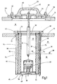
- the in the Fig. 1 shown filter device is used for installation in a container-like fluid reservoir tank 10, comparable to the installation situation after the EP 1 419 807 B1 , From the fluid reservoir tank 10 is shown in the Fig. 1 only the upper tank wall 12 drawn, and an associated receiving wall 14 for fixing the filter device. Between these wall sections 12,14 runs an inlet channel 16 for contaminated fluid, as it comes for example from the hydraulic circuit of a not shown working hydraulics of a construction machine or the like.
- the filter device further comprises a filter element 18 with preferably pleated filter mat 20. Otherwise, the filter element 18 essentially forms a kind of circular cylinder.
- the filter mat 20 is guided between an upper end cap 22 and a lower end cap 24 as parts of the filter element 18.
- the lower end cap 24 has, in the middle and coaxial with the longitudinal axis 26 of the filter device, a per se conventional one Bypass valve 28, which opens at pollution added filter mat 20 and, bypassing the filter mat 20, the fluid can flow untreated through a lower bypass opening 30 in the storage tank 10.
- the filter mat 20 for stiffening outwardly from a support tube or support shell 36 includes, wherein the support tube 36 is preferably circular cylindrical and corresponding, not shown passage openings for the passage of the means of the filter mat 20 cleaned fluid.
- a correspondingly shaped support jacket (not shown) but could also follow the outer contour of the pleated filter mat and inasmuch as to increase the pressure stability of the element outwards to make the support.
- the pertinent supporting jacket also has corresponding passage openings for the fluid medium. The fluid inlet of the uncleaned fluid, coming from the inlet channel 16, via the upper inlet opening 38 of the filter element in the direction of said inner side 32 thereof.
- the filter element 18 is received in a designated as a whole with 40 housing having on its upper side a flange-like widening 42, with which the filter device is supported in this area at the top of the upper tank wall 12.
- Downstream of said widening 42 is a cylindrical housing wall 44, which is designed to be closed towards its underside 46, except for said bypass opening 30.
- the underside 46 of the housing wall 44 forms an independent bottom part and the housing wall 44 is supported with its respective free end of a paragraph-like step of the bottom part 46 and on the flange-like widening 42. So that the described composite of the housing 40 in the in the Fig. 1 shown assembly position remains, are outside circumference of the filter mat 20 with Support tube 36 holding rods 48 arranged, of which in the Fig.
- the housing 40 is inserted into the upper tank wall 12, in this a corresponding circular cylindrical recess 52 is introduced, whose diameter is in any case greater than the outer diameter in the region of the transition between the flange-like widening 42 and the outer circumference of the housing wall 44.
- a cover part 54 as part of the filter device present with a handle 56 for facilitated installation and removal of the filter device in the tank shown 10.
- the cover part 54 has a paragraph-like widening 58, which rests on the top of the receiving wall 14 and a shoulder of the widening 58 engages in the free inner diameter of the receiving wall 14 under investment in the same one.
- an annular sealing element 60 of conventional design. How the particular Fig.
- a magnetic rod 64 Concentric to the longitudinal axis 26 extends a magnetic rod 64, which in particular has the function of a permanent magnet and the direction of the Fig. 1 seen fixed with its upper end in the cover part 54, in particular screwed there and with its other opposite free end, he passes through the inside 32 of the filter element 18.
- the pertinent magnetic rod 64 allows a separation of magnetizable metal components in the fluid to be filtered.
- Both magnetic bar 64 and bypass valve 28 are optional and not necessarily provided for the function of the filter device as a whole.
- the cylindrical housing wall 44 assumes a predeterminable radial distance to the outer peripheral surface of the filter element 18, so that in this respect a fluid flow space 66 is formed.
- the pertinent fluid flow space 66 extends parallel to the outer peripheral surface of the filter element 18, in particular it extends in the axial longitudinal direction parallel to the longitudinal axis 26 of the device between the top of the bottom portion 46 and the bottom of the flange widening 42. Further, the Fluiströmungsraum 66 to the outside substantially bounded by the housing wall 44 and inwardly from the outer peripheral surface of the filter mat 20. If a support jacket or a support tube 36 is used for the filter mat 20, the pertinent outer peripheral surface forms the boundary for the fluid flow space 66th
- a fluid level 68 is shown within the storage tank 10 and the filter element 18 and thus the fluid flow space 66 are partially below the level 68 and partly above it.
- the fluid level 68 changes with respect to the instantaneous position shown in FIG Fig. 1 ,
- the fluid flow space 66 is in the rest of its flow space forth to the passage of the individual support rods 48 (see. Fig. 1 ) is not affected.
- Fig. 1a shows that relates to a different longitudinal section plane than the Fig. 1 but otherwise should refer to the substantially same filter device
- the filter device to individual connecting rods 70 the sake of ease of representation in the Fig. 1 have been omitted and of the three connecting rods 70 are in the Fig. 1a only two shown.
- the connecting rods 70 are connected at the end to the cover part 54 and are otherwise on the upper end cap 22 of the filter element 18 in order to keep this in the installation position shown. In that regard, it is possible to remove by removing the cover member 54 only the exchanged filter element 18 from the housing 40, which otherwise remains in its installed position on the upper tank wall 12.
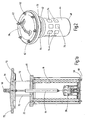
- FIG. 11 is an external view of the filter device of FIG Fig. 1 window-like passage openings 74 are present in the housing wall 44, the ring-like superimposed and circumferentially encircling groups form, the two adjacent groups have an equal axial distance from each other and the individual passage openings 74 within a group in the radial direction also have the same distance dimensions to each other.
- the lower group of fluid level passage openings 74 are still covered and the overlying group of passage openings 74 terminate at the level top into the interior of the tank 10.
- a screen or grid structure layer 76 is disposed within the housing wall 44 and on the inside thereof, which forms a continuous cylinder jacket and all the same identically formed window-like Durthlassö réelleen 74 engages over the edge. So that the structural layer 76 remains on the inside of the housing wall 44, it can be correspondingly fixed by way of a spot weld, not shown.
- an independent grid can also be provided for each window opening 74, which then covers the pertinent window opening from the inside with a peripheral projection.
- structural layer 76 can serve an expanded metal mesh, but also another thin-meshed grid or network in the form of a fabric structure with warp and weft threads.
- the structural layer 76 used in each case preferably has an opening cross section of less than one millimeter per passage point for the multiplicity of passage points.
- the choice of the free opening cross-sections for the passage points of the structural layer depends on environmental conditions, such as the viscosity of the fluid used, in particular in the form of hydraulic oil, which is ultimately also dependent on ambient temperature values
- the window openings 74 are preferably realized in a rectangular shape; however, other opening geometries would also be possible to that extent.
- the free opening cross sections for the passages can be selected such that any gas bubbles present in the cleaned fluid, such as air bubbles, deposit on the thus perforated structure layer 76, with the bubbles for a fluid-level release of the gas the structure layer 76 collected and increased for ease of delivery under the influence of their surface tension in the volume, so that they can easily ascend comparable to the CO 2 beads in a carbonated beverage from the filter device upwards, so far as the fluid in the Tank is effectively degassed. Since hydraulic working devices are often sensitive to gas entry, the extent of the risk of malfunction has been effectively counteracted to that extent.
- a cylindrical structural layer 76 with corresponding passage points (not shown).
- the structural layer 76 is multilayered, so that a stiffer structure for the housing wall 44 is established in order to be able to control the pressure differences occurring in the tank 10 safely.
- the structure shown for the individual passage points to provide the same free opening cross-section would also be conceivable in the structure changed in the direction of the rising fluid flow in the fluid flow space 66 to change the free opening cross-section, in particular to increase uniformly, so as to improve the fluid in the Fluid flow space 66 to achieve.
- a compression spring 78 is provided instead of the connecting rods 70, which extends between the cover part 54 and the housing 40 in order to press the housing 40 of the filter device against the upper side of the upper tank wall 12 when the cover part 54 is fixed.
- the solution according to the Fig. 3 three such superimposed groups on.
- the fluid level is again exemplified by a triangle under reference 68. Substantially in the modified embodiment of the Fig.
- Said shell 82 may be incorporated as an independent component in the fluid flow space 66; However, there is also the possibility that the sheath 82 shown is part of the filter element 18, in particular in the scope of the further passage points 80, and insofar surrounds the filter mat 20 of the filter element 18 in the manner of a support tube or support sheath. Should the oil level in the form of the fluid level 68 fall below the illustrated window-like passage openings 74, an air cushion could unintentionally accumulate there when the working hydraulics are switched off. In any case, this air cushion does not occur if, according to the representation of the Fig. 3 the outer support cylinder of the filter element 18 to below the minimum possible oil level has a non-perforated part, as shown in the Fig. 3 can also be realized by a separate shell 82, for example made of plastic material.
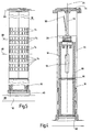
- FIGS. 4 and 5 are in a coaxial arrangement to the longitudinal axis 26 of the filter device two filter elements 18 arranged one above the other, wherein in the direction of the Fig. 4 seen lower filter element 18 of the fine filtration and the overlying element of the coarse filtration. If the fine filtration element 18 is added by soiling, coarse filtration can still be carried out via the upper element 18.
- the filter device is designed to be closed except for the now arranged at the top bypass valve 28 and the contaminated fluid now flows through a passage at the bottom 46 in the respective filter element 18 a.
- the two filter elements 18 are in the middle via a spacer device 84 separated from each other, which has a fluid passage in the middle. Depending on the degree of soiling for the lower fine filter element 18, a fluid fraction then increasingly flows via the upper coarse filter 18. Otherwise, filtered fluid enters the already described fluid flow space 66 from the lower filter element 18.
- FIG. 5 shows how the particular Fig. 5 This time, there are pairs of window-like passage openings 74, with five groups of two arranged in superimposed arrangement. Furthermore, the shows Fig. 5 the two provided lower and upper fluid levels 68 (oil level min./ ⁇ lstand max.) On. As is further from the Fig. 5 results, this time the filter device extends between a tank top 68 and a lower tank chamber 88, which forms the inlet channel 16 for the contaminated fluid so far. For fixing the two superposed filter elements 18 with their respective end caps on the cover part 54 this time serves a single centrally arranged connecting rod 70 and the filter assembly can be by means of a swivel bow handle 90 from the housing wall 44 deploy.
- the respectively used magnetic rod 64 in the manner of a magnetic candle can be easily inspected from the outside during maintenance work and, if necessary, cleaned by hand by means of a suitable cloth.
- the magnetic rod 64 is arranged such that foreign particles uniformly adhere to it, without causing an accumulation of dirt in the area of the bypass valve 28, which would possibly impair the function of the valve.
- the element is particularly in vehicle movements between the Wall regions 12 and 14 well supported, so that it does not come unintentionally to a lifting filter device parts, with the result of an unwanted bypass flow of unfiltered fluid to the clean side of the tank assembly.
- a modular concept is achieved with the filter device according to the invention, which contributes to reducing the production costs.
Landscapes
- Chemical & Material Sciences (AREA)
- Chemical Kinetics & Catalysis (AREA)
- Engineering & Computer Science (AREA)
- Water Supply & Treatment (AREA)
- Filtration Of Liquid (AREA)
- Filtering Of Dispersed Particles In Gases (AREA)
Abstract
Description
Die Erfindung betrifft eine Filtervorrichtung, insbesondere vorgesehen zum Einbau In einen Fluid-Vorratstank, mit mindestens einem vorzugsweise austauschbaren Filterelement, das von innen nach außen von einem Fluid durchströmbar ist und das jeweils unter Beibehalten eines vorgebbaren Radialabstandes und unter Bildung eines Fluidströmungsraumes von einer Gehäusewand umgeben ist, die mehrere Durchlassstellen aufweist, von denen ein Teil unterhalb des jeweiligen veränderbaren Fluidniveaus im Vorratstank und der andere Teil oberhalb dieses Fluidniveaus angeordnet ist. Dahingehende Lösungen werden fachsprachlich auch mit Intank-Lösung bezeichnet.The invention relates to a filter device, in particular provided for installation in a fluid storage tank, with at least one preferably replaceable filter element, which is traversed from the inside to the outside of a fluid and each surrounded by maintaining a predeterminable radial distance and forming a fluid flow space of a housing wall is, which has a plurality of passage points, a part of which is arranged below the respective variable fluid level in the storage tank and the other part above this fluid level. These solutions are also referred to in technical terms as the Intank solution.
Durch die
Eine vergleichbare intank-Lösung ist auch in der
Bei der Filtration mit dahingehenden Intank-Filtervorrichtungen kommt es grundsätzlich, insbesondere bei hohen Arbeitsdrücken und/oder großen Fluidmengen, beim Durchtritt des abzureinigenden Fluids durch das jeweilige Filterelement zum Spritzen und zur Schaumbildung, letzteres bedingt durch Gasblasen, insbesondere gebildet aus Luh, die regelmäßig im vorangehenden hydraulischen Arbeitskreis in das Fluid, insbesondere in Form von Hydrauliköl, gelangen können, was insbesondere der Fall ist, wenn dahingehende Filtervorrichtungen für mobile Maschinen zum Einsatz kommen, wie beispielsweise Bagger, Rad- oder Teleskoplader etc., die umfänglich mit einer Arbeitshydraulik versehen sind, beispielsweise in Form von mittels Pumpen ansteuerbarer und versorgbarer Hydraulikzylinder. Um zu vermeiden, dass bei den bekannten Lösungen das aus dem Filterelement herausspritzende und schaumbildende Fluid in unmittelbaren Kontakt kommt mit der sonstigen Fluid- oder Ölmenge im Vorratstank, sind die Filterelemente in entsprechenden Umfassungsgehäusen innerhalb des Tanks gekammert, die jeweils eine Art Vorberuhigungsraum oder Vorkammer bilden, in denen das abgereinigte Fluid zur Ruhe kommen kann und etwaige Gasblasen nach oben hin auftriebsbedingt austreten können. Die genannten Beruhigungskammern nehmen aber innerhalb des eigentlichen Tankvolumens relativ viel Bauraum ein und führen letztendlich somit auch zu groß aufbauenden Vorratstanks als Ganzes und insbesondere bei hohen Arbeitsdrücken und/oder sehr großen Mengen an zu filtrierendem Fluid genügen die Vorkammervolumen regelmäßig nicht, in ausreichendem Maße eine Beruhigung des Öls vor Abgabe in den eigentlichen Vorratstank zu bewerkstelligen.In the filtration with this Intank filter devices occurs in principle, especially at high working pressures and / or large amounts of fluid in the passage of the fluid to be cleaned through the respective filter element for spraying and foaming, the latter due to gas bubbles, in particular formed from Luh, the regularly in preceding hydraulic working group in the fluid, in particular in the form of hydraulic oil, can pass, which is the case in particular, if the pertinent filter devices for mobile machines used come, such as excavators, wheeled or telescopic loaders, etc., which are circumferentially provided with a working hydraulics, for example in the form of controllable by means of pumps hydraulic cylinders and can be supplied. In order to avoid that in the known solutions, the spurting out of the filter element and foam-forming fluid comes into direct contact with the other fluid or oil quantity in the storage tank, the filter elements are chambered in corresponding Umfassungsgehäusen within the tank, each forming a kind Vorreßigungsraum or prechamber in which the cleaned fluid can come to rest and any gas bubbles can escape upward due to buoyancy. However, the said calming chambers take up a relatively large amount of installation space within the actual tank volume and ultimately lead to large storage tanks as a whole and especially at high working pressures and / or very large amounts of fluid to be filtered, the prechamber volumes do not regularly suffice to a sufficient extent of the oil before discharge into the actual storage tank to accomplish.
Eine Filtervorrichtung der eingangs genannten Art ist aus
Ausgehend von diesem Stand der Technik liegt der Erfindung die Aufgabe zugrunde, die bekannten Lösungen dahingehend weiter zu verbessern, dass sie uneingeschränkt auch für mobile Anwendungen zum Einsatz kommen können und dass unter Beibehalten der Vorteile einer sehr guten Abreinigung des Fluids eine bauraumsparende und kostengünstige Lösung zur Verfügung gestellt ist, mit der auch bei hohen Drücken und/oder sehr großen Mengen von Fluid die problemlose Weitergabe an einen Vorratstank beherrschbar ist.Based on this prior art, the present invention seeks to further improve the known solutions that they can be used without restriction for mobile applications and that while maintaining the benefits of very good cleaning of the fluid space-saving and cost-effective solution for Is made available, with which even at high pressures and / or very large amounts of fluid problem-free transfer to a storage tank is manageable.
Eine dahingehende Aufgabe löst eine Filtervorrichtung mit den Merkmalen des Patentanspruches 1 in seiner Gesamtheit.This object is achieved by a filter device with the features of claim 1 in its entirety.
Gemäß dem kennzeichnenden Teil des Patentanspruchs 1 zeichnet sich eine erfindungsgemäße Filtervorrichtung dadurch aus, dass die jeweiligen Durchlassstellen Teil mindestens einer Sieb-oder Gitterstrukturlage sind, die in der Gehäusewand angeordnete, bevorzugt fensterartige Durchlassöffnungen abdeckt, und dass die freien Öffnungsquerschnitte für die Durchlassstellen der mindestens einen Strukturlage derart gewählt sind, dass etwaig im gereinigten Fluid sich befindende Gasblasen an der derart perforierten Strukturlage abscheidbar und/oder für eine fluidniveaunahe Abgabe sammelbar sind. Vorzugsweise sind die freien Öffnungsquerschnitte für die Durchlassstellen derart gewählt, dass die Gasblasen für eine erleichterte Abgabe unter dem Einfluss ihrer Oberflächenspannung im Volumen vergrößerbar sind.According to the characterizing part of claim 1, a filter device according to the invention is characterized in that the respective passage points are part of at least one screen or lattice structure covering the housing wall, preferably window-like passage openings, and that the free opening cross sections for the passage points of the at least one Structure layer are selected such that any gas bubbles in the cleaned fluid are deposited on the perforated structure layer such and / or collectable for a fluidniveaunahe delivery. Preferably, the free opening cross sections for the Passage sites chosen so that the gas bubbles for ease of delivery under the influence of their surface tension in the volume can be increased.
Dank der Anordnung von Durchlassstellen strömt das in den Fluidströmungsraum eintretende, vom jeweiligen Filterelement gereinigte Fluid im Bereich des jeweiligen Fluidniveaus und oberhalb desselben in laminarer Weise über die zuordenbaren Durchlassstellen in den Vorratstank und die unerwünschte Spritz- oder Schaumbildung beim austretenden Fluid ist derart mit Sicherheit vermieden. Aufgrund der Druckdifferenz zwischen dem einströmendem, nicht gereinigten Fluid und dem abströmendem, gereinigten Fluid kann letzteres im Fluidströmungsraum über das Fluidniveau im Tank angehoben werden bei gleichmäßiger Verteilung entlang der Innenseite der Gehäusewand mit den Durchlassstellen, wozu auch Kapillareffekte mit beitragen können, und der derart entstehende gleichmäßige Fluidfilm ermöglicht dann den spritz- und schaumfreien Austritt aus den genannten Durchlassstellen quer zu der Gehäusewand.Thanks to the arrangement of passage points, the fluid entering the fluid flow space, cleaned by the respective filter element fluid in the region of the respective fluid level and above it in a laminar manner via the assignable passages into the storage tank and the unwanted spattering or foaming at the exiting fluid is avoided with certainty , Due to the pressure difference between the inflowing, unpurified fluid and the effluent, purified fluid latter can be raised in the fluid flow space above the fluid level in the tank with even distribution along the inside of the housing wall with the passage points, which can contribute to capillary effects, and the resulting uniform fluid film then allows the spill and foam-free outlet from said passageways transverse to the housing wall.
Sofern das im Fluidströmungsraum befindliche gereinigte Fluid etwaige Gasblasen, wie Luftblasen, aufweist, werden diese an die jeweilige Durchlassstelle mit abgegeben, die für eine fluidniveaunahe Abgabe innerhalb des Vorratstanks die Blasen sammelt und vorzugsweise für eine erleichterte Abgabe in ihrem Volumen vergrößert. Dergestalt erhalten die Gasblasen einen höheren Auftrieb und separieren sich leichter von der austretenden, gereinigten Fluidmenge, insbesondere derart, dass kein Schaum und keine Spritzbildung entsteht, die ansonsten wiederum die Einbindung von Gas oder Luft in die austretende Fluidmenge begünstigen würden. Sofern die Fluidmenge innerhalb des Vorratstanks im wesentlichen entgast ist, kann bei einer entsprechenden Fluidentnahme und Weitergabe an die Arbeitshydraulik es zu keinen Gasblasen bedingten Ausfällen kommen und Schädigungen der Arbeitshydraulik im Betrieb sind mit Sicherheit vermieden.If the purified fluid in the fluid flow space has any gas bubbles, such as air bubbles, they are delivered to the respective passage point, which collects the bubbles for a fluid-level release within the storage tank and preferably increases their volume for easier dispensing. In this way, the gas bubbles receive a higher buoyancy and separate easily from the exiting, purified amount of fluid, in particular in such a way that no foam and no formation of spray, which would otherwise favor the integration of gas or air in the exiting fluid amount. If the amount of fluid within the storage tank is substantially degassed, failures associated with fluid withdrawal and transfer to the working hydraulics can result in no gas bubbles damage and damage to the working hydraulics during operation are avoided with certainty.
Durch das homogene Austrittsverhalten werden auch gegebenenfalls noch im Tank befindliche Schwebstoffteile nicht aufgewirbelt und auf aufwendige Vorruhekammern im Tank, die im übrigen auch Bauraum einnehmen, kann vollständig verzichtet werden.Due to the homogeneous outlet behavior also suspended in the tank or suspended particulate matter are not stirred up and elaborate Vorruhekammern in the tank, which also occupy space, can be completely dispensed with.
Sollte das Fluidniveau und mithin der Ölspiegel unter die untersten Durchlassstellen absinken, was beispielsweise beim Abschalten der Arbeitshydraulik der Maschine der Fall sein könnte, ist nicht auszuschließen, dass sich dort ein Luftpolster sammelt, das wie bereits dargelegt, gerade nicht erwünscht ist. Um dieser Gefahr zu begegnen, ist bei einer besonders bevorzugten Ausführungsform der erfindungsgemäßen Filtervorrichtung vorgesehen, dass die Gehäusewand zu ihrer Unterseite hin geschlossen ausgebildet ist und dass in den Fluidströmungsraum eine zusätzliche Hülle eingesetzt ist, die unterhalb des anzunehmenden tiefsten Fluidniveaus weitere Durchlassstellen aufweist und bis dahin und oberhalb dieses Niveaus ansonsten eine geschlossene Hüllenfläche ausbildet.If the fluid level and consequently the oil level drop below the lowermost transmission points, which could be the case, for example, when switching off the working hydraulics of the machine, it can not be ruled out that there will accumulate an air cushion which, as already explained, is not desirable. In order to counteract this risk, in a particularly preferred embodiment of the filter device according to the invention, it is provided that the housing wall is closed towards its underside and that an additional sheath is inserted into the fluid flow space, which has further passage points below the lowest fluid level to be assumed and until then and above this level otherwise forms a closed envelope surface.
Alternativ kann auch vorgesehen sein, um diesem Effekt zu begegnen, dass das jeweils eingesetzte Filterelement mit seiner äußeren Hülle, die eine Art Stützrohr, insbesondere Stützzylinder, bildet bis unter den minimal zu erwartenden Ölspiegel (Fluidniveau) im Tank einen ungelochten, geschlossenen Hüllenteil aufweist und darunter befinden sich dann zur Vermeidung des genannten Luftpolsters entsprechend die weiteren Durchlassstellen, vorzugsweise in der Art einer Perforation in der genannten Stützrohrhülle. Insoweit besteht also die Möglichkeit die Hülle als eigenständiges Zusatzteil in den Fluidströmungsraum einzubringen oder das äußere Stützrohr des Filterelementes so zu modifizieren, dass die beschriebene Hüllenfunktion erreicht ist.Alternatively, it can also be provided to counteract this effect that the filter element used in each case with its outer shell, which forms a kind of support tube, in particular support cylinder until under the minimum expected oil level (fluid level) in the tank has an unperforated, closed shell part and underneath, in order to avoid the said air cushion, there are correspondingly the further passage points, preferably in the manner of a perforation in said support tube shell. In that regard, there is the possibility to introduce the shell as an independent additional part in the fluid flow space or to modify the outer support tube of the filter element so that the envelope function described is achieved.
Weitere vorteilhafte Ausführungsform der erfindungsgemäßen Filtervorrichtung sind Gegenstand der sonstigen Unteransprüche.Further advantageous embodiment of the filter device according to the invention are the subject of the other dependent claims.
Im Folgenden wird die erfindungsgemäße Lösung anhand verschiedener Ausführungsbeispiele nach der Zeichnung näher erläutert. Dabei zeigen in prinzipieller und nicht maßstäblicher Weise die
- Fig. 1
- einen Längsschnitt durch ein erstes Ausführungsbeispiel der erfindungsgemäßen Filtervorrichtung;
- Fig. 1A
- eine der
Fig. 1 entsprechende Darstellung, jedoch in einer anderen Schnittebene gezeichnet; - Fig. 2
- eine perspektivische Außenansicht der Filtervorrichtung nach der
Fig. 1 und - Fig. 3
- teilweise aufgeschnitten dargestellt ein zweites Ausführungsbeispiel der Filtervorrichtung;
- Fig. 4 und 5
- ein drittes Ausführungsbeispiel der Filtervorrichtung, einmal im Längsschnitt dargestellt, einmal in der Seitenansicht, wobei das untere Fußteil gleichfalls geschnitten dargestellt ist.
- Fig. 1
- a longitudinal section through a first embodiment of the filter device according to the invention;
- Fig. 1A
- one of the
Fig. 1 corresponding representation, but drawn in another section plane; - Fig. 2
- an external perspective view of the filter device according to the
Fig. 1 and - Fig. 3
- shown partially cut away a second embodiment of the filter device;
- 4 and 5
- a third embodiment of the filter device, once shown in longitudinal section, once in the side view, wherein the lower foot part is also shown cut.
Die in der
Die Filtervorrichtung weist des weiteren ein Filterelement 18 auf mit vorzugsweise plissierter Filtermatte 20. Ansonsten bildet das Filterelement 18 im wesentlichen eine Art Kreiszylinder aus. Die Filtermatte 20 ist zwischen einer oberen Endkappe 22 und einer unteren Endkappe 24 als Teile des Filterelementes 18 geführt. Die untere Endkappe 24 weist mittig und koaxial zur Längsachse 26 der Filtervorrichtung verlaufend ein an sich übliches Bypassventil 28 auf, das bei von Verschmutzungen zugesetzter Filtermatte 20 öffnet und unter Umgehung der Filtermatte 20 das Fluid ungereinigt über eine untere Bypassöffnung 30 in den Vorratstank 10 abströmen läßt. Da die Filtermatte 20 von innen nach außen durchströmt wird, also die Durchströmung von der Innenseite 32 des Filterelementes 18 in Richtung des Inneren 34 des Fluidvorratstanks erfolgt, ist die Filtermatte 20 zur Aussteifung nach außen hin von einem Stützrohr oder Stützmantel 36 umfaßt, wobei das Stützrohr 36 vorzugsweise kreiszylindrisch ausgebildet ist und entsprechende, nicht näher dargestellte Durchlassöffnungen aufweist für den Durchtritt des mittels der Filtermatte 20 abgereinigten Fluids. Ein entsprechend geformter Stützmantel (nicht dargestellt) könnte aber auch der Außenkontur der plissierten Filtermatte nachfolgen und insofern zur Erhöhung der Druckstabilität des Elementes nach außen die Abstützung vornehmen. Auch der dahingehende Stützmantel verfügt über entsprechende Durchlassöffnungen für das Fluidmedium. Der Fluideintritt des ungereinigten Fluids, vom Einlaufkanal 16 kommend, erfolgt über die obere Eintrittsöffnung 38 des Filterelementes in Richtung der genannten Innenseite 32 desselben.The filter device further comprises a
Das Filterelement 18 ist in einem als Ganzes mit 40 bezeichneten Gehäuse aufgenommen, das an seiner Oberseite eine flanschartige Verbreiterung 42 aufweist, mit der sich die Filtervorrichtung in diesem Bereich an der Oberseite der oberen Tankwand 12 abstützt. An die genannte Verbreiterung 42 schließt sich nach unten hin eine zylindrische Gehäusewand 44 an, die zu ihrer Unterseite 46 hin geschlossen ausgebildet ist, bis auf die genannte Bypassöffnung 30. Vorzugsweise bildet die dahingehende Unterseite 46 der Gehäusewand 44 ein eigenständiges Bodenteil aus und die Gehäusewand 44 stützt sich mit ihrem jeweils freien Ende an einer absatzartigen Stufe des Bodenteils 46 ab sowie an der flanschartigen Verbreiterung 42. Damit der beschriebene Verbund des Gehäuses 40 in der in der
Damit das Gehäuse 40 in die obere Tankwand 12 einsetzbar ist, ist in diese eine entsprechende kreiszylindrische Ausnehmung 52 eingebracht, deren Durchmesser jedenfalls größer ist als der Außendurchmesser im Bereich des Überganges zwischen der flanschartigen Verbreiterung 42 und dem Außenumfang der Gehäusewand 44. Ferner ist ein Deckelteil 54 als Teil der Filtervorrichtung vorhanden mit einem Handgriff 56 für den erleichterten Ein- und Ausbau der Filtervorrichtung in den gezeigten Tank 10. Das Deckelteil 54 weist eine absatzartige Verbreiterung 58 auf, die auf der Oberseite der Aufnahmewand 14 aufsteht und ein Absatz der Verbreiterung 58 greift in den freien Innendurchmesser der Aufnahmewand 14 unter Anlage an dieselbe ein. Zur Fluidabdichtung dient in diesem Bereich ein ringförmiges Dichtelement 60 üblicher Bauart. Wie insbesondere die
Konzentrisch zur Längsachse 26 verläuft ein Magnetstab 64, der insbesondere die Funktion eines Permanentmagneten hat und der in Blickrichtung auf die
Wie die
Bei dem Ausführungsbeispiel nach der
Wie die
Wie des Weiteren die
Anstelle einer einzigen Strukturlage 76 kann dem Grunde nach aber auch für jede Fensteröffnung 74 ein eigenständiges Gitter vorgesehen sein, das von der Innenseite her mit einem randseitigen Überstand die dahingehende Fensteröffnung dann abdeckt. Als Strukturlage 76 kann ein Streckmetallgitter dienen, aber auch ein sonstiges dünnmaschiges Gitter oder Netzwerk auch in Form einer Gewebestruktur mit Kett- und Schußfäden. Vorzugsweise weist die jeweils eingesetzte Strukturlage 76 für die Vielzahl an Durchlassstellen pro Durchlassstelle einen Öffnungsquerschnitt von weniger als einem Millimeter auf. Die Wahl der freien Öffnungsquerschnitte für die Durchlassstellen der Strukturlage hängt von Umgebungsbedingungen ab, wie der Viskosität des eingesetzten Fluids, insbesondere in Form des Hydrauliköls, die letztendlich auch mit von Umgebungstemperaturwerten abhängig ist Die Fensteröffnungen 74 sind vorzugsweise in Rechteckform realisiert; andere Öffnungsgeometrien wären aber insoweit gleichfalls möglich.Instead of a single
Nimmt man nun die Filtervorrichtung nach den
In Abhängigkeit der Maschenweite für die Strukturlage 76 lassen sich die freien Öffnungsquerschnitte für die Durchlassstellen derart wählen, dass etwaig im gereinigten Fluid sich befindende Gasblasen, wie Luftblasen, an der derart perforierten Strukturlage 76 sich abscheiden, wobei für eine fluidniveaunahe Abgabe des Gases die Blasen an der Strukturlage 76 gesammelt und für eine erleichterte Abgabe unter dem Einfluss ihrer Oberflächenspannung im Volumen vergrößert werden, so dass diese ohne weiteres vergleichbar den CO2-Perlen bei einem kohlesäurehaltigen Getränk aus der Filtervorrichtung heraus nach oben hin aufsteigen können, so dass insoweit das Fluid im Tank wirksam entgast ist. Da hydraulische Arbeitseinrichtungen häufig empfindlich gegen Gaseintrag sind, ist insoweit der dahingehenden Störungsgefahr wirksam begegnet.Depending on the mesh size for the
Anstelle der in den
Die nachfolgenden Ausführungsbeispiele werden nur noch insoweit erläutert, als sie sich wesentlich von der vorangegangenen Ausführungsform unterscheiden, wobei für dieselben Bauteile mit derselben Funktion auch die bisher verwendeten Bezugszeichen eingesetzt sind und die insoweit getroffenen Ausführungen gelten auch für die geänderten Ausführungsformen.The following embodiments will be explained only insofar as they differ significantly from the preceding embodiment, wherein for the same components with the same function and the previously used reference numerals are used and the extent adopted statements also apply to the modified embodiments.
Bei dem Ausführungsbeispiel nach der
Die genannte Hülle 82 kann als eigenständiges Bauteil in den Fluidströmungsraum 66 eingebracht sein; es besteht aber auch die Möglichkeit, dass die gezeigte Hülle 82 insbesondere im Umfang der weiteren Durchlassstellen 80 Bestandteil des Filterelementes 18 ist und insoweit in der Art eines Stützrohres oder Stützmantels die Filtermatte 20 des Filterelementes 18 umgibt. Sollte der Ölspiegel in Form des Fluidniveaus 68 unter die dargestellten fensterartigen Durchlassöffnungen 74 fallen, könnte beim Abschalten der Arbeitshydraulik sich dort ungewollt ein Luftpolster sammeln. Dieses luftpolster tritt aber jedenfalls nicht auf, wenn gemäß der Darstellung nach der
Bei der Ausführungsform nach den
Wie insbesondere die
Mit der erfindungsgemäßen Filtervorrichtung nach den gezeigten Ausführungsbeispielen ist eine Aufnahme von Schmutzpartikeln im 10 µm-Bereich ohne Weiteres möglich. Verschmutzte Filterelemente 18 lassen sich einfachst tauschen und aufgrund der speziellen Gehäuseanordnung ist der Gefahr der Rückverschmutzung wirksam begegnet. Der jeweils eingesetzte Magnetstab 64 in der Art einer Magnetkerze lässt sich bei Wartungsarbeiten gut von außen einsehen und bei Bedarf von Hand mittels eines geeigneten Tuches abreinigen. Im Übrigen ist der Magnetstab 64 derart angeordnet, dass Fremdpartikel gleichmäßig an ihm anhaften, ohne dass es im Bereich des Bypassventils 28 zu einer Häufung an Verschmutzungen kommen könnte, was gegebenenfalls die Funktion des Ventils beeinträchtigen würde. Das Element ist insbesondere bei Fahrzeugbewegungen zwischen den Wandbereichen 12 und 14 gut abgestützt, so dass es nicht ungewollt zu einem Abheben von Filtervorrichtungsteilen kommt mit der Folge eines ungewollten Bypassstroms von ungefiltertem Fluid auf die Reinseite der Tank-Anordnung. Insgesamt ist mit der erfindungsgemäßen Filtervorrichtung ein modulares Konzept erreicht, was mit dazu beiträgt, die Herstellungskosten zu senken.With the filter device according to the invention according to the embodiments shown, a recording of dirt particles in the 10 micron range is readily possible.
Besonders bedeutsam ist jedoch, dass mit der erfindungsgemäßen Lösung ein homogenes laminares Abströmen des gereinigten Fluids von der Filtervorrichtung zurück in einen Tank möglich ist, ohne dass es zu Spritzeffekten oder zur ungewollten Schaumbildung kommen kann. Aufgrund der eingesetzten Strukturlagen mit den feinmaschigen Durchlassöffnungen ist darüber hinaus das Entgasungsverhalten verbessert und ein schädigender Lufteintrag in das Hydraulikmedium ist mit Sicherheit ausgeschlossen.It is particularly important, however, that with the solution according to the invention, a homogeneous laminar flow of the purified fluid from the filter device back into a tank is possible, without causing syringe effects or unwanted foaming. Due to the structural layers used with the fine-meshed passage openings beyond the degassing behavior is improved and a damaging air entry into the hydraulic medium is excluded with certainty.
Claims (7)
- A filter apparatus, in particular intended for installation in a fluid reservoir tank (10), comprising at least one preferably exchangeable filter element (18) through which fluid can flow from the inside to the outside and which is surrounded, in each case maintaining a presettable radial distance and with formation of a fluid flow space (66), by a housing wall (44) which has a plurality of passage points, some of which are arranged below the respective variable fluid level (68) in the reservoir tank (10), and the rest of which are arranged above this fluid level (68), characterised in that the respective passage points are part of at least one screen or lattice structure layer (76) which covers preferably window-like passage openings (74) arranged in the housing wall (44), and that the clear opening cross-sections for the passage points of the at least one structure layer (76) are chosen such that any gas bubbles to be found in the cleaned fluid can be deposited on the thus perforated structure layer (76) and/or can be collected for delivery close to the fluid level.
- The filter apparatus according to Claim 1, characterised in that the opening cross-sections for the passage points are chosen such that the volume of the gas bubbles can be increased for facilitated delivery due to the effect of their surface tension.
- The filter apparatus according to Claim 1 or 2, characterised in that the passage points respectively have the same clear opening cross-section or that the clear opening cross-sections increase at least partially, preferably uniformly, in the direction of the rising fluid flow in the fluid flow space (66).
- The filter apparatus according to any of the preceding claims, characterised in that the respective structure layer (76) is disposed in front of the housing wall (44) in the flow direction of the fluid through the passage openings (74) in said housing wall (44) and, preferably arranged in the fluid flow space (66), envelops with an edge-sided overlap the respectively assignable window-like passage openings (74).
- The filter apparatus according to any of the preceding claims, characterised in that the passage points disposed within the housing wall (44) are arranged in groups the same distance apart from one another in the direction of the radial and/or axial extension.
- The filter apparatus according to any of the preceding claims, characterised in that defined by the upper side of the housing wall (44) and by a lid part (54) of the apparatus, an inflow channel (16) for fouled fluid is formed or that the inflow channel (16) is formed by a penetration on the bottom side (46) of the housing wall (44) and the housing wall (44) connected to the lid part (54) forms a closed circumferential section.
- The filter apparatus according to any of the preceding claims, characterised in that the housing wall (44) is configured so as to be closed towards its lower side (46) and that an additional sleeve (82) is inserted into the fluid flow space (66), said sleeve having additional passage points (80) below the lowest fluid level (68) to be assumed and forming up to that point and above this level (68) a closed sleeve surface.
Priority Applications (1)
| Application Number | Priority Date | Filing Date | Title |
|---|---|---|---|
| EP13004742.6A EP2682172B1 (en) | 2008-03-04 | 2008-12-18 | Fluid tank with a filter apparatus |
Applications Claiming Priority (2)
| Application Number | Priority Date | Filing Date | Title |
|---|---|---|---|
| DE102008012521A DE102008012521A1 (en) | 2008-03-04 | 2008-03-04 | Filter device and filter element for a pertinent filter device |
| PCT/EP2008/010789 WO2009109212A1 (en) | 2008-03-04 | 2008-12-18 | Filter apparatus and filter element for such a filter apparatus |
Related Child Applications (1)
| Application Number | Title | Priority Date | Filing Date |
|---|---|---|---|
| EP13004742.6A Division EP2682172B1 (en) | 2008-03-04 | 2008-12-18 | Fluid tank with a filter apparatus |
Publications (2)
| Publication Number | Publication Date |
|---|---|
| EP2249941A1 EP2249941A1 (en) | 2010-11-17 |
| EP2249941B1 true EP2249941B1 (en) | 2013-11-20 |
Family
ID=40545774
Family Applications (2)
| Application Number | Title | Priority Date | Filing Date |
|---|---|---|---|
| EP08873163.3A Active EP2249941B1 (en) | 2008-03-04 | 2008-12-18 | Filter apparatus and filter element for such a filter apparatus |
| EP13004742.6A Active EP2682172B1 (en) | 2008-03-04 | 2008-12-18 | Fluid tank with a filter apparatus |
Family Applications After (1)
| Application Number | Title | Priority Date | Filing Date |
|---|---|---|---|
| EP13004742.6A Active EP2682172B1 (en) | 2008-03-04 | 2008-12-18 | Fluid tank with a filter apparatus |
Country Status (4)
| Country | Link |
|---|---|
| US (1) | US20110056875A1 (en) |
| EP (2) | EP2249941B1 (en) |
| DE (1) | DE102008012521A1 (en) |
| WO (1) | WO2009109212A1 (en) |
Cited By (4)
| Publication number | Priority date | Publication date | Assignee | Title |
|---|---|---|---|---|
| DE102015003604A1 (en) | 2015-03-19 | 2016-09-22 | Hydac Filtertechnik Gmbh | filter means |
| DE102015003606A1 (en) | 2015-03-19 | 2016-09-22 | Hydac Filtertechnik Gmbh | filter means |
| WO2016146227A1 (en) | 2015-03-19 | 2016-09-22 | Hydac Filtertechnik Gmbh | Filter apparatus |
| DE102015004795A1 (en) | 2015-04-14 | 2016-10-20 | Rt-Filtertechnik Gmbh | Filter device and filter element |
Families Citing this family (15)
| Publication number | Priority date | Publication date | Assignee | Title |
|---|---|---|---|---|
| DE102009017093A1 (en) * | 2009-04-15 | 2010-11-04 | Hydac Filtertechnik Gmbh | filter means |
| DE102012002534A1 (en) | 2012-02-09 | 2013-08-14 | Hydac Filter Systems Gmbh | Filter device and filter element for such a filter device |
| DE102013204827B4 (en) | 2012-06-11 | 2019-03-21 | Ford Global Technologies, Llc | Fine filter for flowing liquids |
| GB2503762B (en) * | 2013-03-06 | 2014-07-02 | Vexo Internat Uk Ltd | Fluid treatment apparatus & method |
| DE102013007606B4 (en) | 2013-05-03 | 2016-04-21 | Hydac Filter Systems Gmbh | Block filters |
| DE102013011866A1 (en) * | 2013-07-16 | 2015-01-22 | Rt-Filtertechnik Gmbh | filter means |
| DE102013011865A1 (en) * | 2013-07-16 | 2015-01-22 | Rt-Filtertechnik Gmbh | filter means |
| DE102013014453A1 (en) * | 2013-08-30 | 2015-03-05 | Rt-Filtertechnik Gmbh | Filter device for fluids |
| DE102015007692A1 (en) * | 2015-06-09 | 2016-12-15 | Rt-Filtertechnik Gmbh | filter element |
| DE102015016068B4 (en) | 2015-12-11 | 2021-08-19 | Hydac Cooling Gmbh | Device for separating ferromagnetic particles from flowable fluids |
| WO2017209054A1 (en) | 2016-06-03 | 2017-12-07 | ヤマシンフィルタ株式会社 | Filter device |
| IT201600104280A1 (en) * | 2016-10-18 | 2018-04-18 | Rbm Spa | FILTER FOR THE TREATMENT OF A FLUID IN A PIPE, IN PARTICULAR A PIPE OF A WATER NETWORK AND ITS FUNCTIONING METHOD |
| DE102017221016A1 (en) * | 2017-11-24 | 2019-05-29 | Robert Bosch Gmbh | Liquid filter and tank filter system with a liquid filter |
| DE102021002179B3 (en) | 2021-04-24 | 2022-09-29 | Hydac International Gmbh | Device for converting volume flows and hydraulic presses with such a device |
| DE102021005289A1 (en) | 2021-10-23 | 2023-04-27 | Rt-Filtertechnik Gmbh | filter device |
Family Cites Families (64)
| Publication number | Priority date | Publication date | Assignee | Title |
|---|---|---|---|---|
| US231066A (en) * | 1880-08-10 | Filter | ||
| US821360A (en) * | 1905-05-03 | 1906-05-22 | Electric Liquid Purifying And Filtering Company | Filter. |
| US1535768A (en) * | 1920-09-15 | 1925-04-28 | Row & Davis Engineers Inc | Feed-water grease-extractor apparatus |
| US2117361A (en) * | 1933-08-10 | 1938-05-17 | Frank B Netherland | Oil filter with renewable filtering element |
| US2242807A (en) * | 1938-02-21 | 1941-05-20 | Laplant Choate Mfg Co Inc | Oil filter |
| US2366451A (en) * | 1941-07-08 | 1945-01-02 | Andale Co | Strainer |
| NL272124A (en) * | 1960-12-12 | 1900-01-01 | ||
| US3289841A (en) * | 1962-12-26 | 1966-12-06 | Michigan Dynamics Inc | Bidirectional filter |
| US3219194A (en) * | 1963-01-16 | 1965-11-23 | Gen Motors Corp | Filter mass of furred nodules |
| US3262564A (en) * | 1963-05-24 | 1966-07-26 | Pall Corp | Dual valve, dual filter element, constant flow filter assembly |
| US3313417A (en) * | 1963-05-13 | 1967-04-11 | Rosaen Filter Co | Mobile filters |
| US3348686A (en) * | 1964-12-21 | 1967-10-24 | Carroll F Spitzer | Filter unit and vacuum attachment therefor |
| US3441138A (en) * | 1966-01-24 | 1969-04-29 | Parker Hannifin Corp | Reservoir filter and indicator |
| US3493110A (en) * | 1967-04-24 | 1970-02-03 | Parker Hannifin Corp | Multiple filter device |
| US3653512A (en) * | 1970-07-16 | 1972-04-04 | Parker Hannifin Corp | Fluid filter device |
| US3747761A (en) * | 1971-11-03 | 1973-07-24 | Marvel Eng Co | Continuous flow suction filter |
| US3886072A (en) * | 1973-04-30 | 1975-05-27 | Caterpillar Tractor Co | Filter retainer and bypass valve assembly |
| US3853763A (en) * | 1973-07-02 | 1974-12-10 | Caterpillar Tractor Co | In-tank filter and mounting arrangement therefor |
| US4039305A (en) * | 1976-11-17 | 1977-08-02 | Caterpillar Tractor Co. | Apparatus for removing gas from a liquid system |
| US4167483A (en) * | 1978-07-10 | 1979-09-11 | Rosaen Borje O | Fluid filtering device |
| US4261823A (en) * | 1979-07-26 | 1981-04-14 | Summit Engineering Corporation | Storm drain catch basin |
| US4273651A (en) * | 1979-08-20 | 1981-06-16 | Rosaen Nils O | Return line filter |
| US4436633A (en) * | 1981-08-14 | 1984-03-13 | Robinsky Eli I | Filtration thickening method and apparatus |
| US4397745A (en) * | 1982-04-05 | 1983-08-09 | Cecor Incorporated | Filter cartridge for sump cleaner |
| US4401563A (en) * | 1982-07-26 | 1983-08-30 | Douglas Koelfgen | Oil filter cartridge for motorcycles |
| US4539107A (en) * | 1984-07-13 | 1985-09-03 | Ayers William R | Phase separation detecting filter |
| US4645600A (en) * | 1985-04-05 | 1987-02-24 | Filippi Joseph J | In-tank fuel filter |
| JPH064888Y2 (en) * | 1987-05-15 | 1994-02-09 | 株式会社ニフコ | filter |
| US4935128A (en) * | 1988-06-06 | 1990-06-19 | Custom Chrome, Inc. | Motorcycle engine lubricating oil filter apparatus |
| JPH0657252B2 (en) * | 1988-08-26 | 1994-08-03 | テルモ株式会社 | Blood reservoir |
| US5207896A (en) * | 1990-02-09 | 1993-05-04 | Norwalk Wastewater Equipment Company | Wastewater treatment mechanism |
| DE9103400U1 (en) * | 1991-03-20 | 1991-05-29 | Harnisch GmbH Filter-, Apparate- und Anlagenbau, 6922 Meckesheim | Filter cartridge |
| US5236582A (en) * | 1991-12-10 | 1993-08-17 | Sam Yu Pets Corporation | Filter device for an aquatic tank |
| GB2263874B (en) * | 1992-02-05 | 1995-05-17 | M G Electric | Filter for printing equipment dampening system |
| DE9301562U1 (en) * | 1993-02-04 | 1994-03-10 | Liebherr-Werk Bischofshofen Ges.M.B.H., Bischofshofen | Oil filter for filtering hydraulic or engine oil |
| US5718281A (en) * | 1994-05-13 | 1998-02-17 | Contech Division, Spx Corporation | Cooler reservoir/filter holder |
| US5624560A (en) * | 1995-04-07 | 1997-04-29 | Baker Hughes Incorporated | Wire mesh filter including a protective jacket |
| US5759393A (en) * | 1995-05-08 | 1998-06-02 | Nurse, Jr.; Harry L. | Filter device |
| DE19719135A1 (en) * | 1997-05-07 | 1998-11-12 | Argo Gmbh Fuer Fluidtechnik | Filter for spent hydraulic fluid |
| US5904847A (en) * | 1998-08-31 | 1999-05-18 | Bovington; Tom | Septic tank waste water filter |
| US6602408B1 (en) * | 1998-10-30 | 2003-08-05 | Edward B. Berkey | Filtration system for water garden reservoir |
| DE19925635B4 (en) * | 1999-06-04 | 2005-11-03 | ZF Lemförder Metallwaren AG | Hydraulic oil tank |
| US6440303B2 (en) * | 2000-03-02 | 2002-08-27 | Chapin Manufacturing, Inc. | Fluid filter |
| US6533941B2 (en) * | 2001-08-14 | 2003-03-18 | George R. Butler | Flow through drain filter for a stormwater or wastewater catch basin |
| FR2829803B1 (en) * | 2001-09-19 | 2004-03-19 | Delphi Tech Inc | GAS FILTERING DEVICE FOR SUPPLYING A DIESEL ENGINE AND GAS SUPPLY LINE COMPRISING SUCH A DEVICE |
| US6616835B2 (en) * | 2001-09-24 | 2003-09-09 | Jon A. Jensen | Coolant recycling system |
| DE10252410A1 (en) | 2002-11-12 | 2004-05-19 | Hydac Filtertechnik Gmbh | filtering device |
| US6858134B2 (en) * | 2002-12-23 | 2005-02-22 | Arvin Technologies, Inc. | Fluid filtration system including replaceable filter module |
| US7160447B2 (en) * | 2002-12-23 | 2007-01-09 | Purolator Filters Na Llc | Fluid filtration system including replaceable filter module |
| US6913040B2 (en) * | 2003-03-24 | 2005-07-05 | Visteon Global Technologies, Inc. | Hydraulic fluid reservoir |
| US6782926B1 (en) * | 2003-03-25 | 2004-08-31 | Randall L. Hughes | Closed-loop refilling and pressure testing system for modern motor vehicle cooling systems |
| US7252759B2 (en) * | 2003-04-10 | 2007-08-07 | Schroeder Industries, Llc | In-tank return line filter element and hydraulic reservoir with same |
| US6890443B2 (en) * | 2003-04-29 | 2005-05-10 | Amphion International Limited | Spin filter system |
| US7216610B2 (en) * | 2003-08-01 | 2007-05-15 | Stant Manufacturing Inc. | Pressure regulator for engine cooling system |
| DE102004014149B4 (en) | 2004-03-20 | 2007-01-25 | Hydac Filtertechnik Gmbh | filter means |
| JP4948775B2 (en) * | 2004-06-14 | 2012-06-06 | 愛三工業株式会社 | Fuel supply device |
| DE102004032256B3 (en) * | 2004-07-03 | 2005-12-15 | Jungheinrich Ag | Hydraulic unit for industrial trucks |
| US7799235B2 (en) * | 2004-07-23 | 2010-09-21 | Contech Stormwater Solutions, Inc. | Fluid filter system and related method |
| JP4267545B2 (en) * | 2004-09-03 | 2009-05-27 | 愛三工業株式会社 | Fuel pump unit |
| US7449051B2 (en) * | 2005-07-11 | 2008-11-11 | Hewlett-Packard Development Company, L.P. | Separation of liquid and gas from froth |
| JP4613125B2 (en) * | 2005-11-29 | 2011-01-12 | 株式会社Roki | Ion exchange filter |
| US20070221554A1 (en) * | 2006-03-22 | 2007-09-27 | Arvin Technologies, Inc. | Filter with pressure relief |
| US8007948B2 (en) * | 2008-03-14 | 2011-08-30 | GM Global Technology Operations LLC | Ion exchange cartridge for fuel cell applications |
| US8038878B2 (en) * | 2008-11-26 | 2011-10-18 | Mann+Hummel Gmbh | Integrated filter system for a coolant reservoir and method |
-
2008
- 2008-03-04 DE DE102008012521A patent/DE102008012521A1/en not_active Withdrawn
- 2008-12-18 US US12/735,988 patent/US20110056875A1/en not_active Abandoned
- 2008-12-18 WO PCT/EP2008/010789 patent/WO2009109212A1/en active Application Filing
- 2008-12-18 EP EP08873163.3A patent/EP2249941B1/en active Active
- 2008-12-18 EP EP13004742.6A patent/EP2682172B1/en active Active
Cited By (4)
| Publication number | Priority date | Publication date | Assignee | Title |
|---|---|---|---|---|
| DE102015003604A1 (en) | 2015-03-19 | 2016-09-22 | Hydac Filtertechnik Gmbh | filter means |
| DE102015003606A1 (en) | 2015-03-19 | 2016-09-22 | Hydac Filtertechnik Gmbh | filter means |
| WO2016146227A1 (en) | 2015-03-19 | 2016-09-22 | Hydac Filtertechnik Gmbh | Filter apparatus |
| DE102015004795A1 (en) | 2015-04-14 | 2016-10-20 | Rt-Filtertechnik Gmbh | Filter device and filter element |
Also Published As
| Publication number | Publication date |
|---|---|
| EP2682172A3 (en) | 2014-03-19 |
| EP2682172A2 (en) | 2014-01-08 |
| EP2249941A1 (en) | 2010-11-17 |
| DE102008012521A1 (en) | 2009-09-17 |
| US20110056875A1 (en) | 2011-03-10 |
| WO2009109212A1 (en) | 2009-09-11 |
| EP2682172B1 (en) | 2021-06-30 |
Similar Documents
| Publication | Publication Date | Title |
|---|---|---|
| EP2249941B1 (en) | Filter apparatus and filter element for such a filter apparatus | |
| DE4330840C1 (en) | Filter for cleaning liquids | |
| EP3004620B1 (en) | Filter element | |
| DE60220407T2 (en) | REFILLABLE HYBRID FILTER | |
| EP3271043B1 (en) | Filter device | |
| DE102014000903B4 (en) | Filter element and filter device | |
| DE68906180T2 (en) | Fluid filter. | |
| DE102013012918C5 (en) | Liquid filter and filter element, in particular for fuel | |
| DE102013012917B4 (en) | Liquid filters, in particular for fuel | |
| EP3283192B1 (en) | Filter device and filter element | |
| EP1246680A1 (en) | Filter device | |
| EP2054134A1 (en) | Filter candle for a backwash filter | |
| EP3144053B1 (en) | Container for a filter cartridge and filter set | |
| EP2826534B1 (en) | Filter device | |
| DE102021005289A1 (en) | filter device | |
| EP4115964B1 (en) | Filter device | |
| DE102021000062B3 (en) | Filter device and tank device | |
| DE2948868C2 (en) | Filter arrangement for liquids | |
| EP3021953B1 (en) | Filter device | |
| EP3695893B1 (en) | Filter device | |
| DE3916745C2 (en) | Filter device with a tubular filter cartridge | |
| CH712415B1 (en) | Centrifuge as well as insert and base element for a centrifuge. | |
| WO2022233459A1 (en) | Filter device | |
| WO2010075916A1 (en) | Method and device for settling filtration of fluids | |
| EP1419807A1 (en) | Filter device with replaceable filter element |
Legal Events
| Date | Code | Title | Description |
|---|---|---|---|
| PUAI | Public reference made under article 153(3) epc to a published international application that has entered the european phase |
Free format text: ORIGINAL CODE: 0009012 |
|
| 17P | Request for examination filed |
Effective date: 20100817 |
|
| AK | Designated contracting states |
Kind code of ref document: A1 Designated state(s): AT BE BG CH CY CZ DE DK EE ES FI FR GB GR HR HU IE IS IT LI LT LU LV MC MT NL NO PL PT RO SE SI SK TR |
|
| AX | Request for extension of the european patent |
Extension state: AL BA MK RS |
|
| DAX | Request for extension of the european patent (deleted) | ||
| 17Q | First examination report despatched |
Effective date: 20120810 |
|
| GRAP | Despatch of communication of intention to grant a patent |
Free format text: ORIGINAL CODE: EPIDOSNIGR1 |
|
| INTG | Intention to grant announced |
Effective date: 20130529 |
|
| GRAS | Grant fee paid |
Free format text: ORIGINAL CODE: EPIDOSNIGR3 |
|
| GRAA | (expected) grant |
Free format text: ORIGINAL CODE: 0009210 |
|
| AK | Designated contracting states |
Kind code of ref document: B1 Designated state(s): AT BE BG CH CY CZ DE DK EE ES FI FR GB GR HR HU IE IS IT LI LT LU LV MC MT NL NO PL PT RO SE SI SK TR |
|
| REG | Reference to a national code |
Ref country code: GB Ref legal event code: FG4D Free format text: NOT ENGLISH |
|
| REG | Reference to a national code |
Ref country code: CH Ref legal event code: EP |
|
| REG | Reference to a national code |
Ref country code: AT Ref legal event code: REF Ref document number: 641234 Country of ref document: AT Kind code of ref document: T Effective date: 20131215 |
|
| REG | Reference to a national code |
Ref country code: IE Ref legal event code: FG4D Free format text: LANGUAGE OF EP DOCUMENT: GERMAN |
|
| REG | Reference to a national code |
Ref country code: DE Ref legal event code: R096 Ref document number: 502008010989 Country of ref document: DE Effective date: 20140109 |
|
| REG | Reference to a national code |
Ref country code: SE Ref legal event code: TRGR |
|
| REG | Reference to a national code |
Ref country code: NL Ref legal event code: VDEP Effective date: 20131120 |
|
| REG | Reference to a national code |
Ref country code: LT Ref legal event code: MG4D |
|
| PG25 | Lapsed in a contracting state [announced via postgrant information from national office to epo] |
Ref country code: LT Free format text: LAPSE BECAUSE OF FAILURE TO SUBMIT A TRANSLATION OF THE DESCRIPTION OR TO PAY THE FEE WITHIN THE PRESCRIBED TIME-LIMIT Effective date: 20131120 Ref country code: IS Free format text: LAPSE BECAUSE OF FAILURE TO SUBMIT A TRANSLATION OF THE DESCRIPTION OR TO PAY THE FEE WITHIN THE PRESCRIBED TIME-LIMIT Effective date: 20140320 Ref country code: NO Free format text: LAPSE BECAUSE OF FAILURE TO SUBMIT A TRANSLATION OF THE DESCRIPTION OR TO PAY THE FEE WITHIN THE PRESCRIBED TIME-LIMIT Effective date: 20140220 Ref country code: FI Free format text: LAPSE BECAUSE OF FAILURE TO SUBMIT A TRANSLATION OF THE DESCRIPTION OR TO PAY THE FEE WITHIN THE PRESCRIBED TIME-LIMIT Effective date: 20131120 Ref country code: HR Free format text: LAPSE BECAUSE OF FAILURE TO SUBMIT A TRANSLATION OF THE DESCRIPTION OR TO PAY THE FEE WITHIN THE PRESCRIBED TIME-LIMIT Effective date: 20131120 Ref country code: NL Free format text: LAPSE BECAUSE OF FAILURE TO SUBMIT A TRANSLATION OF THE DESCRIPTION OR TO PAY THE FEE WITHIN THE PRESCRIBED TIME-LIMIT Effective date: 20131120 |
|
| PG25 | Lapsed in a contracting state [announced via postgrant information from national office to epo] |
Ref country code: LV Free format text: LAPSE BECAUSE OF FAILURE TO SUBMIT A TRANSLATION OF THE DESCRIPTION OR TO PAY THE FEE WITHIN THE PRESCRIBED TIME-LIMIT Effective date: 20131120 Ref country code: ES Free format text: LAPSE BECAUSE OF FAILURE TO SUBMIT A TRANSLATION OF THE DESCRIPTION OR TO PAY THE FEE WITHIN THE PRESCRIBED TIME-LIMIT Effective date: 20131120 |
|
| BERE | Be: lapsed |
Owner name: RT-FILTERTECHNIK G.M.B.H. Effective date: 20131231 |
|
| PG25 | Lapsed in a contracting state [announced via postgrant information from national office to epo] |
Ref country code: PT Free format text: LAPSE BECAUSE OF FAILURE TO SUBMIT A TRANSLATION OF THE DESCRIPTION OR TO PAY THE FEE WITHIN THE PRESCRIBED TIME-LIMIT Effective date: 20140320 |
|
| REG | Reference to a national code |
Ref country code: DE Ref legal event code: R119 Ref document number: 502008010989 Country of ref document: DE |
|
| PG25 | Lapsed in a contracting state [announced via postgrant information from national office to epo] |
Ref country code: EE Free format text: LAPSE BECAUSE OF FAILURE TO SUBMIT A TRANSLATION OF THE DESCRIPTION OR TO PAY THE FEE WITHIN THE PRESCRIBED TIME-LIMIT Effective date: 20131120 |
|
| REG | Reference to a national code |
Ref country code: CH Ref legal event code: PL |
|
| REG | Reference to a national code |
Ref country code: DE Ref legal event code: R097 Ref document number: 502008010989 Country of ref document: DE |
|
| PG25 | Lapsed in a contracting state [announced via postgrant information from national office to epo] |
Ref country code: SK Free format text: LAPSE BECAUSE OF FAILURE TO SUBMIT A TRANSLATION OF THE DESCRIPTION OR TO PAY THE FEE WITHIN THE PRESCRIBED TIME-LIMIT Effective date: 20131120 Ref country code: RO Free format text: LAPSE BECAUSE OF FAILURE TO SUBMIT A TRANSLATION OF THE DESCRIPTION OR TO PAY THE FEE WITHIN THE PRESCRIBED TIME-LIMIT Effective date: 20131120 Ref country code: PL Free format text: LAPSE BECAUSE OF FAILURE TO SUBMIT A TRANSLATION OF THE DESCRIPTION OR TO PAY THE FEE WITHIN THE PRESCRIBED TIME-LIMIT Effective date: 20131120 Ref country code: MC Free format text: LAPSE BECAUSE OF FAILURE TO SUBMIT A TRANSLATION OF THE DESCRIPTION OR TO PAY THE FEE WITHIN THE PRESCRIBED TIME-LIMIT Effective date: 20131120 Ref country code: CZ Free format text: LAPSE BECAUSE OF FAILURE TO SUBMIT A TRANSLATION OF THE DESCRIPTION OR TO PAY THE FEE WITHIN THE PRESCRIBED TIME-LIMIT Effective date: 20131120 |
|
| REG | Reference to a national code |
Ref country code: IE Ref legal event code: MM4A |
|
| REG | Reference to a national code |
Ref country code: DE Ref legal event code: R119 Ref document number: 502008010989 Country of ref document: DE Effective date: 20140701 |
|
| PLBE | No opposition filed within time limit |
Free format text: ORIGINAL CODE: 0009261 |
|
| STAA | Information on the status of an ep patent application or granted ep patent |
Free format text: STATUS: NO OPPOSITION FILED WITHIN TIME LIMIT |
|
| PG25 | Lapsed in a contracting state [announced via postgrant information from national office to epo] |
Ref country code: DK Free format text: LAPSE BECAUSE OF FAILURE TO SUBMIT A TRANSLATION OF THE DESCRIPTION OR TO PAY THE FEE WITHIN THE PRESCRIBED TIME-LIMIT Effective date: 20131120 |
|
| 26N | No opposition filed |
Effective date: 20140821 |
|
| GBPC | Gb: european patent ceased through non-payment of renewal fee |
Effective date: 20140220 |
|
| PG25 | Lapsed in a contracting state [announced via postgrant information from national office to epo] |
Ref country code: CH Free format text: LAPSE BECAUSE OF NON-PAYMENT OF DUE FEES Effective date: 20131231 Ref country code: IE Free format text: LAPSE BECAUSE OF NON-PAYMENT OF DUE FEES Effective date: 20131218 Ref country code: LI Free format text: LAPSE BECAUSE OF NON-PAYMENT OF DUE FEES Effective date: 20131231 Ref country code: BE Free format text: LAPSE BECAUSE OF NON-PAYMENT OF DUE FEES Effective date: 20131231 Ref country code: DE Free format text: LAPSE BECAUSE OF NON-PAYMENT OF DUE FEES Effective date: 20140701 |
|
| REG | Reference to a national code |
Ref country code: DE Ref legal event code: R073 Ref document number: 502008010989 Country of ref document: DE |
|
| PG25 | Lapsed in a contracting state [announced via postgrant information from national office to epo] |
Ref country code: GB Free format text: LAPSE BECAUSE OF NON-PAYMENT OF DUE FEES Effective date: 20140220 |
|
| PG25 | Lapsed in a contracting state [announced via postgrant information from national office to epo] |
Ref country code: SI Free format text: LAPSE BECAUSE OF FAILURE TO SUBMIT A TRANSLATION OF THE DESCRIPTION OR TO PAY THE FEE WITHIN THE PRESCRIBED TIME-LIMIT Effective date: 20131120 |
|
| REG | Reference to a national code |
Ref country code: DE Ref legal event code: R074 Ref document number: 502008010989 Country of ref document: DE |
|
| REG | Reference to a national code |
Ref country code: DE Ref legal event code: R074 Ref document number: 502008010989 Country of ref document: DE Effective date: 20150419 Ref country code: DE Ref legal event code: R097 Ref document number: 502008010989 Country of ref document: DE Effective date: 20140821 |
|
| PG25 | Lapsed in a contracting state [announced via postgrant information from national office to epo] |
Ref country code: TR Free format text: LAPSE BECAUSE OF FAILURE TO SUBMIT A TRANSLATION OF THE DESCRIPTION OR TO PAY THE FEE WITHIN THE PRESCRIBED TIME-LIMIT Effective date: 20131120 Ref country code: CY Free format text: LAPSE BECAUSE OF FAILURE TO SUBMIT A TRANSLATION OF THE DESCRIPTION OR TO PAY THE FEE WITHIN THE PRESCRIBED TIME-LIMIT Effective date: 20131120 |
|
| PG25 | Lapsed in a contracting state [announced via postgrant information from national office to epo] |
Ref country code: BG Free format text: LAPSE BECAUSE OF FAILURE TO SUBMIT A TRANSLATION OF THE DESCRIPTION OR TO PAY THE FEE WITHIN THE PRESCRIBED TIME-LIMIT Effective date: 20131120 Ref country code: HU Free format text: LAPSE BECAUSE OF FAILURE TO SUBMIT A TRANSLATION OF THE DESCRIPTION OR TO PAY THE FEE WITHIN THE PRESCRIBED TIME-LIMIT; INVALID AB INITIO Effective date: 20081218 Ref country code: LU Free format text: LAPSE BECAUSE OF NON-PAYMENT OF DUE FEES Effective date: 20131218 |
|
| PGRI | Patent reinstated in contracting state [announced from national office to epo] |
Ref country code: DE Effective date: 20150416 |
|
| PG25 | Lapsed in a contracting state [announced via postgrant information from national office to epo] |
Ref country code: GR Free format text: LAPSE BECAUSE OF NON-PAYMENT OF DUE FEES Effective date: 20131120 Ref country code: MT Free format text: LAPSE BECAUSE OF FAILURE TO SUBMIT A TRANSLATION OF THE DESCRIPTION OR TO PAY THE FEE WITHIN THE PRESCRIBED TIME-LIMIT Effective date: 20131120 |
|
| REG | Reference to a national code |
Ref country code: FR Ref legal event code: PLFP Year of fee payment: 8 |
|
| PG25 | Lapsed in a contracting state [announced via postgrant information from national office to epo] |
Ref country code: GR Free format text: LAPSE BECAUSE OF FAILURE TO SUBMIT A TRANSLATION OF THE DESCRIPTION OR TO PAY THE FEE WITHIN THE PRESCRIBED TIME-LIMIT Effective date: 20140221 |
|
| REG | Reference to a national code |
Ref country code: FR Ref legal event code: PLFP Year of fee payment: 9 |
|
| REG | Reference to a national code |
Ref country code: FR Ref legal event code: PLFP Year of fee payment: 10 |
|
| REG | Reference to a national code |
Ref country code: FR Ref legal event code: PLFP Year of fee payment: 11 |
|
| PGFP | Annual fee paid to national office [announced via postgrant information from national office to epo] |
Ref country code: SE Payment date: 20231024 Year of fee payment: 16 Ref country code: IT Payment date: 20231212 Year of fee payment: 16 Ref country code: FR Payment date: 20231031 Year of fee payment: 16 Ref country code: DE Payment date: 20231231 Year of fee payment: 16 Ref country code: AT Payment date: 20231211 Year of fee payment: 16 |