EP3496211A1 - Elektrische verbindungsleitung - Google Patents
Elektrische verbindungsleitung Download PDFInfo
- Publication number
- EP3496211A1 EP3496211A1 EP17205935.4A EP17205935A EP3496211A1 EP 3496211 A1 EP3496211 A1 EP 3496211A1 EP 17205935 A EP17205935 A EP 17205935A EP 3496211 A1 EP3496211 A1 EP 3496211A1
- Authority
- EP
- European Patent Office
- Prior art keywords
- electrical
- cap
- electrical connection
- connection line
- line
- Prior art date
- Legal status (The legal status is an assumption and is not a legal conclusion. Google has not performed a legal analysis and makes no representation as to the accuracy of the status listed.)
- Granted
Links
- 238000007789 sealing Methods 0.000 claims abstract description 32
- 238000003780 insertion Methods 0.000 claims abstract description 19
- 230000037431 insertion Effects 0.000 claims abstract description 19
- 238000000926 separation method Methods 0.000 claims description 11
- 238000004519 manufacturing process Methods 0.000 claims description 6
- 238000003825 pressing Methods 0.000 claims 1
- 238000010276 construction Methods 0.000 description 2
- 241001295925 Gegenes Species 0.000 description 1
- 230000032683 aging Effects 0.000 description 1
- 238000002485 combustion reaction Methods 0.000 description 1
- 230000001419 dependent effect Effects 0.000 description 1
- 238000006073 displacement reaction Methods 0.000 description 1
- 230000000694 effects Effects 0.000 description 1
- 238000001746 injection moulding Methods 0.000 description 1
- 238000009413 insulation Methods 0.000 description 1
- 239000000463 material Substances 0.000 description 1
- 230000013011 mating Effects 0.000 description 1
- 239000002184 metal Substances 0.000 description 1
- 238000003801 milling Methods 0.000 description 1
- 239000011343 solid material Substances 0.000 description 1
- 239000000243 solution Substances 0.000 description 1
Images


Classifications
-
- H—ELECTRICITY
- H01—ELECTRIC ELEMENTS
- H01R—ELECTRICALLY-CONDUCTIVE CONNECTIONS; STRUCTURAL ASSOCIATIONS OF A PLURALITY OF MUTUALLY-INSULATED ELECTRICAL CONNECTING ELEMENTS; COUPLING DEVICES; CURRENT COLLECTORS
- H01R13/00—Details of coupling devices of the kinds covered by groups H01R12/70 or H01R24/00 - H01R33/00
- H01R13/46—Bases; Cases
- H01R13/52—Dustproof, splashproof, drip-proof, waterproof, or flameproof cases
- H01R13/5205—Sealing means between cable and housing, e.g. grommet
-
- B—PERFORMING OPERATIONS; TRANSPORTING
- B60—VEHICLES IN GENERAL
- B60R—VEHICLES, VEHICLE FITTINGS, OR VEHICLE PARTS, NOT OTHERWISE PROVIDED FOR
- B60R16/00—Electric or fluid circuits specially adapted for vehicles and not otherwise provided for; Arrangement of elements of electric or fluid circuits specially adapted for vehicles and not otherwise provided for
- B60R16/02—Electric or fluid circuits specially adapted for vehicles and not otherwise provided for; Arrangement of elements of electric or fluid circuits specially adapted for vehicles and not otherwise provided for electric constitutive elements
- B60R16/0207—Wire harnesses
- B60R16/0215—Protecting, fastening and routing means therefor
-
- H—ELECTRICITY
- H01—ELECTRIC ELEMENTS
- H01R—ELECTRICALLY-CONDUCTIVE CONNECTIONS; STRUCTURAL ASSOCIATIONS OF A PLURALITY OF MUTUALLY-INSULATED ELECTRICAL CONNECTING ELEMENTS; COUPLING DEVICES; CURRENT COLLECTORS
- H01R11/00—Individual connecting elements providing two or more spaced connecting locations for conductive members which are, or may be, thereby interconnected, e.g. end pieces for wires or cables supported by the wire or cable and having means for facilitating electrical connection to some other wire, terminal, or conductive member, blocks of binding posts
- H01R11/11—End pieces or tapping pieces for wires, supported by the wire and for facilitating electrical connection to some other wire, terminal or conductive member
-
- H—ELECTRICITY
- H01—ELECTRIC ELEMENTS
- H01R—ELECTRICALLY-CONDUCTIVE CONNECTIONS; STRUCTURAL ASSOCIATIONS OF A PLURALITY OF MUTUALLY-INSULATED ELECTRICAL CONNECTING ELEMENTS; COUPLING DEVICES; CURRENT COLLECTORS
- H01R13/00—Details of coupling devices of the kinds covered by groups H01R12/70 or H01R24/00 - H01R33/00
- H01R13/46—Bases; Cases
- H01R13/502—Bases; Cases composed of different pieces
- H01R13/506—Bases; Cases composed of different pieces assembled by snap action of the parts
-
- H—ELECTRICITY
- H01—ELECTRIC ELEMENTS
- H01R—ELECTRICALLY-CONDUCTIVE CONNECTIONS; STRUCTURAL ASSOCIATIONS OF A PLURALITY OF MUTUALLY-INSULATED ELECTRICAL CONNECTING ELEMENTS; COUPLING DEVICES; CURRENT COLLECTORS
- H01R13/00—Details of coupling devices of the kinds covered by groups H01R12/70 or H01R24/00 - H01R33/00
- H01R13/58—Means for relieving strain on wire connection, e.g. cord grip, for avoiding loosening of connections between wires and terminals within a coupling device terminating a cable
- H01R13/582—Means for relieving strain on wire connection, e.g. cord grip, for avoiding loosening of connections between wires and terminals within a coupling device terminating a cable the cable being clamped between assembled parts of the housing
- H01R13/5825—Means for relieving strain on wire connection, e.g. cord grip, for avoiding loosening of connections between wires and terminals within a coupling device terminating a cable the cable being clamped between assembled parts of the housing the means comprising additional parts captured between housing parts and cable
-
- H—ELECTRICITY
- H01—ELECTRIC ELEMENTS
- H01R—ELECTRICALLY-CONDUCTIVE CONNECTIONS; STRUCTURAL ASSOCIATIONS OF A PLURALITY OF MUTUALLY-INSULATED ELECTRICAL CONNECTING ELEMENTS; COUPLING DEVICES; CURRENT COLLECTORS
- H01R13/00—Details of coupling devices of the kinds covered by groups H01R12/70 or H01R24/00 - H01R33/00
- H01R13/58—Means for relieving strain on wire connection, e.g. cord grip, for avoiding loosening of connections between wires and terminals within a coupling device terminating a cable
- H01R13/59—Threaded ferrule or bolt operating in a direction parallel to the cable or wire
-
- H—ELECTRICITY
- H01—ELECTRIC ELEMENTS
- H01R—ELECTRICALLY-CONDUCTIVE CONNECTIONS; STRUCTURAL ASSOCIATIONS OF A PLURALITY OF MUTUALLY-INSULATED ELECTRICAL CONNECTING ELEMENTS; COUPLING DEVICES; CURRENT COLLECTORS
- H01R13/00—Details of coupling devices of the kinds covered by groups H01R12/70 or H01R24/00 - H01R33/00
- H01R13/62—Means for facilitating engagement or disengagement of coupling parts or for holding them in engagement
- H01R13/629—Additional means for facilitating engagement or disengagement of coupling parts, e.g. aligning or guiding means, levers, gas pressure electrical locking indicators, manufacturing tolerances
- H01R13/631—Additional means for facilitating engagement or disengagement of coupling parts, e.g. aligning or guiding means, levers, gas pressure electrical locking indicators, manufacturing tolerances for engagement only
-
- H—ELECTRICITY
- H01—ELECTRIC ELEMENTS
- H01R—ELECTRICALLY-CONDUCTIVE CONNECTIONS; STRUCTURAL ASSOCIATIONS OF A PLURALITY OF MUTUALLY-INSULATED ELECTRICAL CONNECTING ELEMENTS; COUPLING DEVICES; CURRENT COLLECTORS
- H01R43/00—Apparatus or processes specially adapted for manufacturing, assembling, maintaining, or repairing of line connectors or current collectors or for joining electric conductors
- H01R43/20—Apparatus or processes specially adapted for manufacturing, assembling, maintaining, or repairing of line connectors or current collectors or for joining electric conductors for assembling or disassembling contact members with insulating base, case or sleeve
Definitions
- the invention relates to an electrical connection line for establishing an electrical connection between two electrical devices.
- an electrical connection line for establishing an electrical connection between two electrical devices.
- the invention has for its object to provide an electrical connection line for connecting electrical units, which avoids the disadvantages of the prior art and is robust against the influence of vibration, as well as inexpensive to manufacture.
- an electrical connection line comprising a plug housing, an electrical line, a ring element, an elastic sealing element and a cap.
- the connector housing has a tubular insertion area for inserting the electrical lead into the connector housing.
- the insertion region is aligned along a longitudinal axis of the electrical line and has a constriction.
- the cap is attached to the connector housing with retaining means.
- the cap has an opening for passing the electric wire.
- the ring element at least partially surrounds the electrical line and the sealing element surrounds the electrical line.
- the ring element and the sealing element are arranged between the constriction and the cap.
- the clearance having the electrical line within the plug housing is eliminated by the ring element, at least in the area where the ring element contacts both the plug housing and the electrical lead. Vibrations that act on the electrical line outside the plug housing and also cause it to vibrate can propagate less from this area, in the direction of the contact element.
- This construction prevents or at least reduces the vibrations of the contact element within the plug housing resulting from the electrical conduction. As a result, an increased wear of the contact element is avoided and the service life and reliability of the electrical connection is improved.
- the electrical connection line is inexpensive to manufacture, since it is to produce standard production equipment.
- the terms electrical line and electrical cable or cable used here all mean an electrical line which is known from the prior art. Wherein these electrical leads have a conductive metallic core (solid material or strands) and a non-conductive, the core encircling insulation.
- the constriction has at least one, with respect to the longitudinal axis inclined and the cap opposite, the first guide surface and the ring member has a, relative to the longitudinal axis in a second guide angle inclined and the first guide surface opposite, second guide surface.
- the opposite guide surfaces form the contact surface between the connector housing and ring element.
- the first guide surface extends from an inner surface of the tubular insertion region, at a first guide angle to the longitudinal axis, in the tubular insertion region, thereby forming a funnel-shaped structure.
- the first guide surface is inclined in the direction of the contact element, so that a force acting on the ring element, along the longitudinal axis, in the direction of the contact element, urges the ring element in the direction of the electrical line. This results in a force that tries to reduce the diameter of the ring element.
- the first guide angle and the second guide angle preferably have the same value in relation to the longitudinal axis. If both guide surfaces have the same angle with respect to the longitudinal axis, they lie flat against each other in the contact areas and can easily move relative to one another.
- the first guide angle and the second guide angle have a value of 45 ° with respect to the longitudinal axis.
- a value of 45 ° allows a moderate reduction of the diameter of the ring element with moderate effort.
- the first guide surface is formed by a plurality of first partial surfaces, wherein the first partial surfaces, on ribs which project into the tubular insertion region, are arranged.
- the division of the first guide surface in the first part surfaces makes it possible to save material and weight in the connector housing. Wherein the functionality is maintained.
- the second guide surface of the ring element is pressed along the longitudinal axis of the elastic sealing element, elastically against the first guide surface of the constriction.
- the sealing element presses, over the entire lifetime of the electrical connection line, the ring element elastically in the direction of the contact element.
- the ring element consists of an annular body having a separation point.
- a ring element with a trend point inserted is much more flexible when deformed radially.
- the ring element can be radially deformed with little effort and demolds itself when the power is removed.
- the size of the diameter change is essentially dependent on the size of the separation point.
- the separation point should be small in relation to the overall size. In practice, the separation point should not be more than 10% of the total.
- the ring element can be made of metal or plastic. Wherein the separation point can be introduced in metallic ring elements by sawing or milling. In plastic ring elements, the separation point can already be provided in the injection molding tool.
- the separation point extends diagonally to the axis of rotation of the annular body. Due to the location of the trend location or the arrangement of the section through the ring element, properties of the ring element can be positively changed.
- the ring member has a base from which a plurality of fingers extend.
- the base adjoins the sealing element.
- the fingers are distributed parallel to the longitudinal axis along the circumference of the ring element.
- the second guide surface is formed by a plurality of second partial surfaces, which are arranged at the finger ends.
- the fingers of the ring element are flexible, so that they can deform. Each individual finger has a small distance to the neighboring finger. If all the fingers are deformed inwards, they move toward the neighboring fingers, forming a smaller opening than in the unformed state. In this smaller opening, the electrical line can be held in the position without play.
- the ring element has a reduced diameter as long as the second guide surface of the ring element along the longitudinal axis against the first guide surface of Narrowing is pressed.
- the ring member is pressed with its inner circumference against the outer circumference of the electric wire, as long as the first guide surface is pressed against the second guide surface. As a result, a mechanical connection between the electrical line and the connector housing is maintained.
- the elastic sealing element between the cap and the ring member is elastically deformed.
- the elastic sealing element is elastically deformed between the cap and the ring element and thereby generates the force required to press the ring element in the direction of the contact element.
- the holding means for attaching the cap to the connector housing comprise latching hooks which cooperate with projections on the connector housing to hold the cap on the connector housing.
- the electrical connection line is designed for use in vehicles. Especially in vehicles, problems resulting from vibrations are known.
- the inventive electrical connection line is particularly suitable for this application.
- FIG. 1 shows an electrical connection line according to the prior art in a sectional view.
- An electrical connection line 10 comprising a plug housing 100, an electrical lead 20, an elastic sealing element 60 and a cap 80.
- the plug housing 100 has a tubular insertion region 102 for inserting the electrical lead 20 into the plug housing 100.
- a contact element 200 is attached to the electrical lead 20 and fixed in the plug housing 100.
- the insertion region 102 is aligned along a longitudinal axis X of the electrical line 20 and has a constriction 104.
- the cap 80 is secured to the connector housing 100 with retaining means.
- the cap 80 has an opening 82 for passing the electrical lead 20.
- the sealing element 60 surrounds the electrical line 20.
- the sealing element 60 is arranged between the constriction 104 and the cap 80.
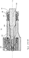
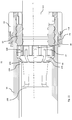
- FIG. 2 shows details of the inventive electrical connection line in a sectional view.
- An electrical connection line 10 comprising a plug housing 100, an electrical lead 20 having a lead end 22, a ring member 40, a resilient sealing member 60, and a cap 80.
- the plug housing 100 has a tubular insertion portion 102 for inserting the electrical lead 20 into the plug housing 100 on.
- the insertion region 102 is along a longitudinal axis X of aligned electrical line 20 and has a constriction 104.
- the cap 80 is secured to the connector housing 100 with retaining means.
- the cap 80 has an opening 82 for passing the electrical lead 20.
- the ring element 40 at least partially surrounds the electrical line and the sealing element 60 surrounds the electrical line.
- the ring member 40 and the sealing member 60 are disposed between the throat 104 and the cap 80.
- FIG. 3 shows details of the sectional view FIG. 2
- the constriction 104 has at least one, with respect to the longitudinal axis X inclined and the cap 80 opposite, the first guide surface 106.
- the ring element 40 has a second guide surface 42 inclined relative to the longitudinal axis X in a second guide angle 44 and opposite the first guide surface 106.
- the first guide surface 106 extends from an inner surface 108 of the tubular insertion region 102, at a first guide angle 120 to the longitudinal axis X, into the tubular insertion region 102, thereby forming a funnel-shaped structure.
- the first guide angle 120 and the second guide angle 44 have the same value with respect to the longitudinal axis X.
- the first guide angle 120 and the second guide angle 44 have a value of 45 ° with respect to the longitudinal axis X.
- the elastic sealing member 60 is elastically deformed between the cap 80 and the ring member 40.
- the ring member 40 and the second guide surface 42 of the ring member 40 are elastically pressed against the first guide surface 106 of the restriction 104 along the longitudinal axis X of the elastic sealing member 60.
- the ring member 40 has a reduced diameter as long as the second guide surface 42 of the ring member 40 along the longitudinal axis X against the first guide surface 106 of the constriction 104 is pressed.
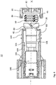
- FIG. 4 shows a sectional view of the inventive electrical connection line, partially mounted.
- the retaining means for attaching the cap 80 to the connector housing 100 includes latching hooks 84 that cooperate with protrusions 130 on the connector housing 100 to hold the cap on the connector housing 100
- FIG. 5 shows the force and the direction of movement of the ring member and the plug housing in a schematic representation.
- the force F which pushes the ring element 40 against the plug housing 100 along the longitudinal axis X has the result that the two parts move in opposite directions.
- the ring element 40 accompanies along the first guide surface 106 of the plug housing 100.
- the first guide angle 120 of the second guide angle 44 must have an angle of less than 90 ° to the longitudinal axis X.
- a first guide angle of 45 ° and a second guide angle of 45 ° form a good compromise of effort and resulting displacement distance.
- FIG. 6 shows a sectional view of a connector housing in a sectional view.
- the first guide surface 106 is formed by a plurality of first partial surfaces 106b.
- the first partial surfaces 106b are arranged on ribs 110 which project into the tubular insertion region 102.
- FIG. 7 shows a perspective view of a ring member 40 of the inventive electrical connection line 10.
- the ring member 40 consists of an annular body having a separation point 46.
- the separation point 46 extends diagonally to the axis of rotation of the annular body 40.
- FIG. 8 shows a sectional view of an alternative connector housing 100 in a sectional view.
- the insertion region 102 tapers along the first guide surface 106 and extends as a constriction 104 along the longitudinal axis X.
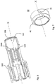
- FIG. 9 shows a perspective view of an alternative ring element of the inventive electrical connection line 10.
- the ring member 40 has a base 48 from which a plurality of fingers 48 extend.
- the fingers 49 extend parallel to the longitudinal axis X of the base 48.
- the fingers 49 are arranged along the circumference of the ring member 40.
- the second guide surface 42 is formed by a plurality of second partial surfaces 42b, which are arranged at the finger ends.
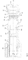
- FIG. 10 shows a sectional view of an alternative embodiment of the inventive electrical connection line, partially mounted.
- the base 48 of the ring element 40 is arranged on the side facing the sealing element 60.
- the second partial surfaces 42b are arranged opposite the first guide surface 106.
- FIG. 11 shows details of in FIG. 10 shown alternative embodiment, in the assembled state.
- the annular element 40 is in its end position in the connector housing 100.
- the elastic sealing element 60 presses against the base 48 and thus also the entire ring element 40 in the direction of the constriction 104.
- the second partial surfaces 42b slide along the first guide surface 106 whereby the fingers 49 in the direction of electrical line 20 are formed.
- the sealing element 60 is held in position by the cap 80. Wherein the cap 80 is held in position by the cooperation of a latching hook 84 on the cap 80 and a projection 130 on the plug housing 100.
Landscapes
- Engineering & Computer Science (AREA)
- Manufacturing & Machinery (AREA)
- Mechanical Engineering (AREA)
- Connector Housings Or Holding Contact Members (AREA)
Abstract
Description
- Die Erfindung betrifft eine elektrische Verbindungsleitung, zum Herstellen einer elektrischen Verbindung zwischen zwei elektrischen Vorrichtungen. Insbesondere zum Verbinden von elektrischen Vorrichtungen in Fahrzeugen sowie ein Verfahren zum Herstellen einer elektrischen Verbindungsleitung.
- Bei modernen Kraftfahrzeugantrieben, werden in einigen Bereichen sehr hochfrequente Vibrationen erzeugt. Schnell drehende Aggregate wie Turbolader, die zur Leistungssteigerung bei Verbrennungsmotoren eingesetzt werden, erzeugen solche hochfrequenten Vibrationen. Werden elektrische Leitungen in der Nähe dieser Aggregate angeordnet, sind auch diese den Vibrationen ausgesetzt. Insbesondere elektrische Steckverbindungen, die den Vibrationen ausgesetzt sind, weisen bereits nach kurzer Zeit negative Veränderungen auf. Die Steckergehäuse der Steckverbindungen sind so konstruiert, dass zwischen den Abmessungen der Kontaktelemente und dem elektrischen Kabel ein minimales Spiel vorhanden ist, um eine Montage der Kontaktelemente in das Steckergehäuse zu ermöglichen. Dieses notwendige Spiel ermöglicht jedoch eine geringe Bewegung der Kontaktelemente und des elektrischen Kabels, wenn sie Vibrationen ausgesetzt werden. Obwohl sehr klein, führen diese kleinen Bewegungen zu erhöhtem Verschleiß, Kontaktschwierigkeiten und möglicherweise Unterbrechungen der elektrischen Leitfähigkeit. Um die Bewegungen zu minimieren werden im Stand der Technik elastische Elemente eingesetzt. Festsitzt zwischen Stecker und Gegenstecker über Klemmrippen sollen Eigenbewegungen zumindest hier ausschließen. Elastische Gummidichtungen im Steckergehäuse, die das elektrische Kabel umgeben, sollen das elektrische Kabel gegen Feuchtigkeit dichten und die Vibrationen dämpfen. All diese Lösungen funktionieren bis zu einem gewissen Grad. Allerdings wird das Problem, insbesondere bei hochfrequenten Vibrationen, nicht zufriedenstellend gelöst.
- Der Erfindung liegt die Aufgabe zu Grunde eine elektrische Verbindungsleitung zum Verbinden von elektrischen Aggregaten bereitzustellen, die die Nachteile des Stands der Technik vermeidet und robust gegenüber dem Einfluss von Vibrationen, sowie preiswert herzustellen ist.
- Die Aufgabe wird durch eine elektrische Verbindungsleitung nach Anspruch 1 gelöst.
- Insbesondere durch eine elektrische Verbindungsleitung umfassend ein Steckergehäuse, eine elektrische Leitung, ein Ringelement, ein elastisches Dichtelement und eine Kappe. Das Steckergehäuse weist einen röhrenförmigen Einführbereich, zum Einführen der elektrischen Leitung in das Steckergehäuse, auf. Der Einführbereich ist entlang einer Längsachse der elektrischen Leitung ausgerichtet und weist eine Verengung auf. Die Kappe ist mit Haltemitteln am Steckergehäuse befestigt. Die Kappe weist eine Öffnung zum Hindurchführen der elektrischen Leitung auf. Das Ringelement umgibt die elektrische Leitung zumindest teilweise und das Dichtelement umgibt die elektrische Leitung. Das Ringelement und das Dichtelement sind zwischen der Verengung und der Kappe angeordnet.
- Bei der erfinderischen, elektrischen Verbindungsleitung wird das Spiel, das die elektrische Leitung innerhalb des Steckergehäuses hat, durch das Ringelement, zumindest in dem Bereich wo das Ringelement sowohl das Steckergehäuse als auch die elektrische Leitung berührt, eliminiert. Vibrationen, die außerhalb des Steckergehäuses auf die elektrische Leitung wirken und diese ebenfalls vibrieren lassen, können sich von diesem Bereich aus, in Richtung des Kontaktelements, weniger stark fortpflanzen. Dieser Aufbau verhindert bzw. verringert zumindest die, von der elektrischen Leitung herrührenden, Vibrationen des Kontaktelements innerhalb des Steckergehäuses. Dadurch wird ein erhöhter Verschleiß des Kontaktelements vermieden und die Lebensdauer und Zuverlässigkeit der elektrischen Verbindung verbessert. Wobei die elektrische Verbindungsleitung preiswert herzustellen ist, da sie mit Standard Produktionsanlagen herzustellen ist. Die hier verwendeten Begriffe elektrische Leitung und elektrisches Kabel bzw. Kabel meinen alle eine elektrische Leitung die aus dem Stand der Technik bekannt ist. Wobei diese elektrischen Leitungen einen leitfähigen metallischen Kern (Vollmaterial oder Litzen) und eine nichtleitende, den Kern umlaufende Isolation aufweist.
- Ein Verfahren zum Herstellen einer elektrischen Verbindungsleitung umfasst die Schritte:
- Bereitstellen eines Steckergehäuses, einer elektrischen Leitung, eines Ringelements, eines elastischen Dichtelements, einer Kappe und eines Kontaktelements;
- Hindurchschieben eines Leitungsendes der elektrischen Leitung durch die Öffnung der Kappe;
- Aufschieben des elastischen Dichtelements auf das Leitungsende der elektrischen Leitung;
- Aufschieben des Ringelements auf das Leitungsende der elektrischen Leitung;
- Hindurchschieben des Leitungsendes durch den rohrförmigen Einführbereich des Steckergehäuses;
- Anbringen und elektrisch Verbinden des Kontaktelements an das Leitungsende der elektrischen Leitung;
- Einschieben der Leitung, sodass das Kontaktelement in das Steckergehäuse bewegt wird und dort einrastet;
- Schieben der Kappe in Richtung des Steckergehäuses bis die Haltemittel die Kappe am Steckergehäuse fixiert haben, wobei das Ringelement gegen eine Verengung im Steckergehäuse gepresst wird und dadurch die elektrische Leitung im Steckergehäuse fixiert.
- Bevorzugt weist die Verengung mindestens eine, im Bezug zur Längsachse geneigte und der Kappe gegenüberliegende, erste Führungsfläche auf und das Ringelement weist eine, im Bezug zur Längsachse in einem zweiten Führungswinkel geneigte und der ersten Führungsfläche gegenüberliegende, zweite Führungsfläche auf. Die sich gegenüberliegenden Führungsflächen bilden die Kontaktfläche zwischen Steckergehäuse und Ringelement.
- Besonders bevorzugt erstreckt sich die erste Führungsfläche von einer inneren Oberfläche des röhrenförmigen Einführbereichs, in einem ersten Führungswinkel zur Längsachse, in den röhrenförmigen Einführbereich und bildet dabei eine trichterförmige Struktur. Die erste Führungsfläche ist in Richtung des Kontaktelements geneigt, damit eine Kraft, die auf das Ringelement, entlang der Längsachse, in die Richtung des Kontaktelements wirkt, das Ringelement in Richtung der elektrischen Leitung drängt. Daraus resultiert eine Kraft, die versucht den Durchmesser des Ringelements zu reduzieren.
- Bevorzugt weisen der erste Führungswinkel und der zweite Führungswinkel den gleichen Wert im Bezug zur Längsachse auf. Weisen beide Führungsflächen den gleichen Winkel im Bezug zur Längsachse auf liegen sie in den Kontaktbereichen plan aneinander und können sich leicht gegeneinander verschieben.
- Besonders bevorzugt weisen der erste Führungswinkel und der zweite Führungswinkel einen Wert von 45° im Bezug zur Längsachse auf. Ein Wert von 45° ermöglicht bei moderatem Kraftaufwand eine moderate Verringerung des Durchmessers des Ringelements.
- Bevorzugt wird die erste Führungsfläche durch eine Vielzahl von Ersten Teilflächen gebildet, wobei die Ersten Teilflächen, an Rippen, die in den röhrenförmigen Einführbereich ragen, angeordnet sind. Die Aufteilung der ersten Führungsfläche in Ersten Teilflächen, ermöglicht es, Material und Gewicht beim Steckergehäuse einzusparen. Wobei die Funktionsfähigkeit erhalten bleibt.
- Bevorzugt wird die zweite Führungsfläche des Ringelements entlang der Längsachse von dem elastischen Dichtelement, elastisch gegen die erste Führungsfläche der Verengung gepresst. Das Dichtelement presst, über die gesamte Lebenszeit der elektrischen Verbindungsleitung, das Ringelement elastisch in Richtung des Kontaktelements. Dadurch werden Alterungserscheinungen, die bei starren Konstruktionen auftreten können, vermieden.
- Besonders bevorzugt besteht das Ringelement aus einem ringförmigen Körper, der eine Trennstelle aufweist. Ein Ringelement bei dem eine Trendstelle eingefügt wurde, ist wesentlich flexibler wenn es radial verformt wird. Das Ringelement kann mit wenig Kraftaufwand radial verformt werden und entformt sich selbstständig wenn die Kraft entfernt wird. Die Größe der Durchmesseränderung ist im Wesentlichen von der Größe der Trennstelle abhängig. Allerdings sollte die Trennstelle im Verhältnis zum Gesamtumfang klein gewählt werden. In der Praxis sollte die Trennstelle nicht mehr als 10 % vom Gesamtumfang betragen. Das Ringelement kann aus Metall oder Kunststoff hergestellt werden. Wobei die Trennstelle bei metallischen Ringelementen durch Sägen oder Fräsen eingebracht werden kann. Bei Ringelementen aus Kunststoff kann die Trennstelle bereits im Spritzgusswerkzeug vorgesehen werden.
- Bevorzugt verläuft die Trennstelle diagonal zur Rotationsachse des ringförmigen Körpers. Durch die Lage der Trendstelle bzw. der Anordnung des Schnitts durch das Ringelement können Eigenschaften des Ringelements positiv verändert werden.
- Bevorzugt weist das Ringelement eine Basis auf von der sich eine Mehrzahl von Fingern erstrecken. Die Basis grenzt an das Dichtelement an. Die Finger sind parallel zur Längsachse, entlang des Umfangs des Ringelements verteilt. Die zweite Führungsfläche wird durch eine Vielzahl von zweiten Teilflächen gebildet, die an den Fingerenden angeordnet sind. Die Finger des Ringelements sind flexibel, sodass sie sich verformen können. Jeder einzelne Finger hat einen geringen Abstand zum benachbarten Finger. Werden alle Finger nach innen verformt bewegen sie sich auf die benachbarten Finger zu und bilden dadurch eine kleinere Öffnung als im ungeformten Zustand. In dieser kleineren Öffnung kann die elektrische Leitung spielfrei in der Position gehalten werden.
- Besonders bevorzugt weist das Ringelement einen verringerten Durchmesser auf solange die zweite Führungsfläche des Ringelements entlang der Längsachse gegen die erste Führungsfläche der Verengung gepresst wird. Das Ringelement wird mit seinem inneren Umfang gegen den äußeren Umfang der elektrischen Leitung gedrückt, solange die erste Führungsfläche gegen die zweite Führungsfläche gedrückt wird. Dadurch bleibt eine mechanische Verbindung zwischen der elektrischen Leitung und dem Steckergehäuse erhalten.
- Bevorzugt ist das elastische Dichtelement zwischen der Kappe und dem Ringelement elastisch verformt. Das elastische Dichtelement ist zwischen der Kappe und dem Ringelement elastisch verformt und erzeugt dadurch die benötigte Kraft, um das Ringelement in Richtung des Kontaktelements zu pressen.
- Bevorzugt umfassen die Haltemittel zum Befestigen der Kappe am Steckergehäuse Rasthaken, die mit Vorsprüngen am Steckergehäuse kooperieren um die Kappe am Steckergehäuse zu halten. Dieser Aufbau hat sich in der Technik als besonders robust und preiswert etabliert. Es sind allerdings auch andere Befestigungsmöglichkeiten denkbar.
- Bevorzugt ist die elektrische Verbindungsleitung für den Einsatz in Fahrzeugen ausgebildet. Besonders bei Fahrzeugen sind Probleme, die von Vibrationen herrühren, bekannt. Die erfinderische elektrische Verbindungsleitung ist für diese Anwendung besonders geeignet.
- Nachfolgend wird die Erfindung anhand einer vorteilhaften Ausführungsform rein beispielhaft unter Bezugnahme auf die beigefügten Zeichnungen beschrieben. Es zeigen:
-
Fig. 1 zeigt eine elektrische Verbindungsleitung nach dem Stand der Technik in einer Schnittdarstellung. -
Fig. 2 zeigt die erfinderische elektrische Verbindungsleitung in einer Schnittdarstellung. -
Fig. 3 zeigt Details der Schnittdarstellung ausFigur 2 . -
Fig. 4 zeigt eine Schnittdarstellung der erfinderischen elektrischen Verbindungsleitung, teilweise montiert. -
Fig. 5 zeigt die Krafteinwirkung und die Bewegungsrichtung des Ringelements und des Steckergehäuses in einer Prinzipdarstellung. -
Fig. 6 zeigt eine Schnittdarstellung eines Steckergehäuses in Schnittdarstellung. -
Fig. 7 zeigt eine perspektivische Darstellung des Ringelements der erfinderischen elektrischen Verbindungsleitung. -
Fig. 8 zeigt eine Schnittdarstellung eines alternativen Steckergehäuses in Schnittdarstellung. -
Fig. 9 zeigt eine perspektivische Darstellung eines alternativen Ringelements der erfinderischen elektrischen Verbindungsleitung. -
Fig. 10 zeigt eine Schnittdarstellung einer alternativen Ausführungsform eines der erfinderischen elektrischen Verbindungsleitung, teilweise montiert. -
Fig. 11 zeigt Details der inFigur 10 gezeigten alternativen Ausführungsform, in montiertem Zustand. - Im Folgenden werden bevorzugte Ausgestaltungen der Erfindung näher beschrieben. Ähnliche oder korrespondierende Einzelheiten des erfindungsgemäßen Gegenstandes sind mit denselben Bezugszeichen versehen.
-
Figur 1 zeigt eine elektrische Verbindungsleitung nach dem Stand der Technik in einer Schnittdarstellung. Eine elektrische Verbindungsleitung 10 umfassend ein Steckergehäuse 100, eine elektrische Leitung 20, ein elastisches Dichtelement 60 und eine Kappe 80. Das Steckergehäuse 100 weist einen röhrenförmigen Einführbereich 102 zum Einführen der elektrischen Leitung 20 in das Steckergehäuse 100 auf. Ein Kontaktelement 200 ist an der elektrischen Leitung 20 angebracht und im Steckergehäuse 100 befestigt. Der Einführbereich 102 ist entlang einer Längsachse X der elektrischen Leitung 20 ausgerichtet und weist eine Verengung 104 auf. Die Kappe 80 ist mit Haltemittel am Steckergehäuse 100 befestigt. Die Kappe 80 weist eine Öffnung 82 zum Hindurchführen der elektrischen Leitung 20 auf. Das Dichtelement 60 umgibt die elektrische Leitung 20. Das Dichtelement 60 ist zwischen der Verengung 104 und der Kappe 80 angeordnet. -
Figur 2 zeigt Details der erfinderischen elektrischen Verbindungsleitung in einer Schnittdarstellung. Eine elektrische Verbindungsleitung 10, umfassend ein Steckergehäuse 100, eine elektrische Leitung 20 mit einem Leitungsende 22, einen Ringelement 40, ein elastisches Dichtelement 60 und eine Kappe 80. Das Steckergehäuse 100 weist einen röhrenförmigen Einführbereich 102 zum Einführen der elektrischen Leitung 20 in das Steckergehäuse 100 auf. Der Einführbereich 102 ist entlang einer Längsachse X der elektrischen Leitung 20 ausgerichtet und weist eine Verengung 104 auf. Die Kappe 80 ist mit Haltemittel am Steckergehäuse 100 befestigt. Die Kappe 80 weist eine Öffnung 82 zum Hindurchführen der elektrischen Leitung 20 auf. Das Ringelement 40 umgibt die elektrische Leitung zumindest teilweise und das Dichtelement 60 umgibt die elektrische Leitung. Das Ringelement 40 und das Dichtelement 60 sind zwischen der Verengung 104 und der Kappe 80 angeordnet. -
Figur 3 zeigt Details der Schnittdarstellung ausFigur 2 . Die Verengung 104 weist mindestens eine, im Bezug zur Längsachse X geneigte und der Kappe 80 gegenüberliegende, erste Führungsfläche 106 auf. Das Ringelement 40 weist eine, im Bezug zur Längsachse X in einem zweiten Führungswinkel 44 geneigte und der ersten Führungsfläche 106 gegenüberliegende, zweite Führungsfläche 42 auf. Die erste Führungsfläche 106 erstreckt sich von einer inneren Oberfläche 108 des röhrenförmigen Einführbereichs 102, in einem ersten Führungswinkel 120 zur Längsachse X, in den röhrenförmigen Einführbereichs 102 und bildet dabei eine trichterförmige Struktur. Der erste Führungswinkel 120 und der zweite Führungswinkel 44 weisen den gleichen Wert im Bezug zur Längsachse X auf. Der erste Führungswinkel 120 und der zweite Führungswinkel 44 weisen einen Wert von 45° im Bezug zur Längsachse X auf. Das elastische Dichtelement 60 ist zwischen der Kappe 80 und dem Ringelement 40 elastisch verformt. Das Ringelement 40 und die zweite Führungsfläche 42 des Ringelements 40 wird entlang der Längsachse X von dem elastischen Dichtelement 60, elastisch gegen die erste Führungsfläche 106 der Verengung 104 gepresst. Das Ringelement 40 weist einen verringerten Durchmesser auf solange die zweite Führungsfläche 42 des Ringelements 40 entlang der Längsachse X gegen die erste Führungsfläche 106 der Verengung 104 gepresst wird. -
Figur 4 zeigt eine Schnittdarstellung der erfinderischen elektrischen Verbindungsleitung, teilweise montiert. Das Haltemittel zum Befestigen der Kappe 80 am Steckergehäuse 100 umfasst Rasthaken 84, die mit Vorsprüngen 130 am Steckergehäuse 100 kooperieren, um die Kappe am Steckergehäuse 100 zu halten -
Figur 5 zeigt die Krafteinwirkung und die Bewegungsrichtung des Ringelements und des Steckergehäuses in einer Prinzipdarstellung. Die Kraft F die entlang der Längsachse X das Ringelement 40 gegen das Steckergehäuse 100 drückt, hat zur Folge, dass sich die beiden Teile entgegengesetzt zueinander bewegen. Das Ringelement 40 begleitet entlang der ersten Führungsfläche 106 des Steckergehäuses 100. Damit dieser Effekt auftritt muss der erste Führungswinkel 120 der zweite Führungswinkel 44 einen Winkel von kleiner als 90° zur Längsachse X aufweisen. Ein erster Führungswinkel von 45° und ein zweiter Führungswinkel von 45° bilden einen guten Kompromiss aus Kraftaufwand und resultierender Verschiebungsstrecke. -
Figur 6 zeigt eine Schnittdarstellung eines Steckergehäuses in Schnittdarstellung. Die erste Führungsfläche 106 wird durch eine Vielzahl von ersten Teilflächen 106b gebildet. Die ersten Teilflächen 106b sind an Rippen 110, die in den röhrenförmigen Einführbereich 102 ragen, angeordnet. -
Figur 7 zeigt eine perspektivische Darstellung eines Ringelements 40 der erfinderischen elektrischen Verbindungsleitung 10. Das Ringelement 40 besteht aus einem ringförmigen Körper, der eine Trennstelle 46 aufweist. Die Trennstelle 46 verläuft diagonal zur Rotationsachse des ringförmigen Körpers 40. -
Figur 8 zeigt eine Schnittdarstellung eines alternativen Steckergehäuses 100 in Schnittdarstellung. Der Einführbereich 102 verjüngt sich entlang der ersten Führungsfläche 106 und erstreckt sich als Verengung 104 entlang der Längsachse X. -
Figur 9 zeigt eine perspektivische Darstellung eines alternativen Ringelements der erfinderischen elektrischen Verbindungsleitung 10. Das Ringelement 40 weist eine Basis 48 auf von der sich eine Mehrzahl von Fingern 48 erstrecken. Die Finger 49 erstrecken sich parallel zur Längsachse X von der Basis 48. Die Finger 49 sind entlang des Umfangs des Ringelements 40 angeordnet. Die zweite Führungsfläche 42 wird durch eine Vielzahl von zweiten Teilflächen 42b gebildet, die an den Fingerenden angeordnet sind. -
Figur 10 zeigt eine Schnittdarstellung einer alternativen Ausführungsform eines der erfinderischen elektrischen Verbindungsleitung, teilweise montiert. Die Basis 48 des Ringelements 40 ist an der dem Dichtelement 60 zugewandten Seite angeordnet. Die zweiten Teilflächen 42b sind gegenüber der ersten Führungsfläche 106 angeordnet. -
Fig. 11 zeigt Details der inFigur 10 gezeigten alternativen Ausführungsform, in montiertem Zustand. Das Ringelement 40 befindet in seiner Endposition im Steckergehäuse 100. Das elastische Dichtelement 60 drückt gegen die Basis 48 und somit auch das gesamte Ringelement 40 in Richtung der Verengung 104. Die zweiten Teilflächen 42b gleiten entlang der ersten Führungsfläche 106 wodurch die Finger 49 in Richtung der elektrischen Leitung 20 geformt werden. Das Dichtelement 60 wird durch die Kappe 80 in Position gehalten. Wobei die Kappe 80 durch die Kooperation eines Rasthakens 84 an der Kappe 80 und eines Vorsprung 130 am Steckergehäuse 100 in Position gehalten wird.
Claims (15)
- Elektrische Verbindungsleitung (10) umfassend ein Steckergehäuse, (100) eine elektrische Leitung (20), einen Ringelement (40), ein elastisches Dichtelement (60) und eine Kappe (80), wobei das Steckergehäuse (100) einen röhrenförmigen Einführbereich (102) zum Einführen der elektrischen Leitung (20) in das Steckergehäuse (100) aufweist, wobei der Einführbereich (102) entlang einer Längsachse (X) der elektrischen Leitung (20) ausgerichtet ist und eine Verengung (104) aufweist, die Kappe (80) ist mit Haltemitteln am Steckergehäuse (100) befestigt, die Kappe (80) weist eine Öffnung (82) zum Hindurchführen der elektrischen Leitung (20) auf, wobei das Ringelement (40) die elektrische Leitung zumindest teilweise umgibt und das Dichtelement (60) die elektrische Leitung umgibt, wobei das Ringelement (40) und das Dichtelement (60) zwischen der Verengung (104) und der Kappe (80) angeordnet sind.
- Elektrische Verbindungsleitung (10) nach Anspruch 1, wobei die Verengung (104) mindestens eine, im Bezug zur Längsachse (X) geneigte und der Kappe (80) gegenüberliegende, erste Führungsfläche (106) aufweist und wobei das Ringelement (40) eine, im Bezug zur Längsachse (X) in einem zweiten Führungswinkel (44) geneigte und der ersten Führungsfläche (106) gegenüberliegende, zweite Führungsfläche (42) aufweist.
- Elektrische Verbindungsleitung (10) nach dem vorhergehenden Anspruch, wobei sich die erste Führungsfläche (106) von einer inneren Oberfläche (108) des röhrenförmigen Einführbereichs (102), in einem ersten Führungswinkel (120) zur Längsachse (X), in den röhrenförmigen Einführbereichs (102) erstreckt und dabei eine trichterförmige Struktur bildet.
- Elektrische Verbindungsleitung (10) nach dem vorhergehenden Anspruche, wobei der erste Führungswinkel (120) und der zweite Führungswinkel (44) den gleichen Wert im Bezug zur Längsachse (X) aufweisen.
- Elektrische Verbindungsleitung (10) nach Anspruch 3, wobei der erste Führungswinkel (120) und der zweite Führungswinkel (44) einen Wert von 45° im Bezug zur Längsachse (X) aufweisen.
- Elektrische Verbindungsleitung (10) nach einem der Ansprüche 2 bis 5, wobei die erste Führungsfläche (106) durch eine Vielzahl von Ersten Teilflächen (106b) gebildet wird, wobei die Ersten Teilflächen (106b), an Rippen (110), die in den röhrenförmigen Einführbereich (102) ragen, angeordnet sind.
- Elektrische Verbindungsleitung (10) nach einem der Ansprüche 2 bis 6, wobei die zweite Führungsfläche (42) des Ringelements (40) entlang der Längsachse (X) von dem elastischen Dichtelement (60), elastisch gegen die erste Führungsfläche (106) der Verengung (104) gepresst wird.
- Elektrische Verbindungsleitung (10) nach einem der vorhergehenden Ansprüche, wobei das Ringelement (40) aus einem ringförmigen Körper besteht, der eine Trennstelle (46) aufweist.
- Elektrische Verbindungsleitung (10) nach dem vorhergehenden Anspruch, wobei die Trennstelle (46) diagonal zur Rotationsachse des ringförmigen Körpers verläuft.
- Elektrische Verbindungsleitung (10), nach einem der Ansprüche 2 bis 7, wobei das Ringelement (40) eine Basis (48) aufweist von der sich eine Mehrzahl von Fingern (49) erstrecken, wobei die Basis (48) an das Dichtelement (60) angrenzt und wobei sich die Finger (49), parallel zur Längsachse (X), verteilt entlang des Umfangs des Ringelements (40), von der Basis (48) erstrecken, wobei die zweite Führungsfläche (42) durch eine Vielzahl von zweiten Teilflächen (42b) gebildet wird, die an den Fingerenden angeordnet sind.
- Elektrische Verbindungsleitung (10) nach einem der Ansprüche 2 bis 6, wobei das Ringelement (40) einen verringerten Durchmesser aufweist solange die zweite Führungsfläche (42) des Ringelements (40) entlang der Längsachse (X) gegen die erste Führungsfläche (106) der Verengung (104) gepresst wird.
- Elektrische Verbindungsleitung (10) nach einem der vorhergehenden Ansprüche, wobei das elastisches Dichtelement (60) zwischen der Kappe (80) und dem Ringelement (40) elastisch verformt ist.
- Elektrische Verbindungsleitung (10) nach einem der vorhergehenden Ansprüche, wobei die Haltemittel zum Befestigen der Kappe (80) am Steckergehäuse (100) Rasthaken (84) umfasst, die mit Vorsprüngen (130) am Steckergehäuse (100) kooperieren, um die Kappe am Steckergehäuse (100) zu halten.
- Verfahren zum Herstellen einer elektrischen Verbindungsleitung (10) nach einem der vorhergehenden Ansprüche, umfassend die Schritte:Bereitstellen eines Steckergehäuses (100), eine elektrische Leitung (20), eines Ringelements (40), eines elastischen Dichtelements (60) einer Kappe (80) und eines Kontaktelements (200);Hindurchschieben eines Leitungsendes (22) der elektrischen Leitung (20) durch die Öffnung (82) der Kappe (80);aufschieben des elastischen Dichtelements (60) auf das Leitungsende (22) der elektrischen Leitung (20);Aufschieben des Ringelements (40) auf das Leitungsende (22) der elektrischen Leitung (20);Hindurchschieben des Leitungsendes (22) durch den rohrförmigen Einführbereich (102), durch das Stecker Gehäuse (100) hindurch;Anbringen und elektrisch Verbinden des Kontaktelements (200) anders Leitungsende (22) der elektrischen Leitung (20);Zurückziehen der Leitung (20), sodass das Kontaktelement (200) in das Steckergehäuse (100) bewegt wird und dort einrastet;Schieben der Kappe (80) in Richtung des Steckergehäuses (100) bis die Haltemittel die Kappe (80) am Steckergehäuse (100) fixiert, wobei das Ringelement (40) gegen eine Verengung (104) im Steckergehäuse (100) gepresst wird und dadurch die elektrische Leitung (20) im Steckergehäuse (100) fixiert.
- Fahrzeug mit einer elektrischen Verbindungsleitung (10) nach einem der Ansprüche 1-13.
Priority Applications (3)
| Application Number | Priority Date | Filing Date | Title |
|---|---|---|---|
| EP17205935.4A EP3496211B1 (de) | 2017-12-07 | 2017-12-07 | Elektrische verbindungsleitung |
| US16/203,717 US10749291B2 (en) | 2017-12-07 | 2018-11-29 | Electrical connecting cable |
| CN201811478600.3A CN109969102A (zh) | 2017-12-07 | 2018-12-05 | 电连接线缆 |
Applications Claiming Priority (1)
| Application Number | Priority Date | Filing Date | Title |
|---|---|---|---|
| EP17205935.4A EP3496211B1 (de) | 2017-12-07 | 2017-12-07 | Elektrische verbindungsleitung |
Publications (2)
| Publication Number | Publication Date |
|---|---|
| EP3496211A1 true EP3496211A1 (de) | 2019-06-12 |
| EP3496211B1 EP3496211B1 (de) | 2020-09-09 |
Family
ID=60627559
Family Applications (1)
| Application Number | Title | Priority Date | Filing Date |
|---|---|---|---|
| EP17205935.4A Active EP3496211B1 (de) | 2017-12-07 | 2017-12-07 | Elektrische verbindungsleitung |
Country Status (3)
| Country | Link |
|---|---|
| US (1) | US10749291B2 (de) |
| EP (1) | EP3496211B1 (de) |
| CN (1) | CN109969102A (de) |
Families Citing this family (2)
| Publication number | Priority date | Publication date | Assignee | Title |
|---|---|---|---|---|
| JP7001963B2 (ja) * | 2018-05-16 | 2022-01-20 | 住友電装株式会社 | コネクタ |
| DE202019002833U1 (de) * | 2019-07-09 | 2020-07-16 | Kuka Deutschland Gmbh | Kabeldurchführung für einen Steuerungsschrank |
Citations (3)
| Publication number | Priority date | Publication date | Assignee | Title |
|---|---|---|---|---|
| US20110130035A1 (en) * | 2009-11-30 | 2011-06-02 | Japan Aviation Electronics Industry, Limited | Connector |
| US20140273540A1 (en) * | 2013-03-15 | 2014-09-18 | Aqua Products, Inc. | Waterproof separable swivel connector |
| EP3249757A1 (de) * | 2016-05-26 | 2017-11-29 | Hosiden Corporation | Wasserdichter steckverbinder |
Family Cites Families (18)
| Publication number | Priority date | Publication date | Assignee | Title |
|---|---|---|---|---|
| US3010747A (en) * | 1958-06-02 | 1961-11-28 | Lewis A Bondon | Connectors for rods or tubes |
| US4030741A (en) * | 1975-01-20 | 1977-06-21 | Harvey Hubbell, Incorporated | Cord grips |
| US4549755A (en) * | 1983-06-16 | 1985-10-29 | Efcor, Inc. | Armored cable connector |
| EP0175827A1 (de) * | 1984-09-24 | 1986-04-02 | Société d'Exploitation des Procédés Maréchal S.E.P.M. (Société Anonyme) | Vorrichtung zum Anklemmen eines elektrischen Kabels am Griff eines Steckers |
| DE3633208A1 (de) * | 1986-09-30 | 1988-04-07 | Spinner Gmbh Elektrotech | Abgedichteter kabelverbinder |
| US5059747A (en) * | 1989-12-08 | 1991-10-22 | Thomas & Betts Corporation | Connector for use with metal clad cable |
| US5567174A (en) * | 1994-06-02 | 1996-10-22 | The Ericson Manufacturing Co. | Water tight grease filled connector with strain relief |
| JP2785714B2 (ja) * | 1994-09-08 | 1998-08-13 | 住友電装株式会社 | シール用ゴム栓の固定構造 |
| US5951327A (en) * | 1997-09-29 | 1999-09-14 | Thomas & Betts International, Inc. | Connector for use with multiple sizes of cables |
| US6846988B2 (en) * | 2002-01-18 | 2005-01-25 | Adc Telecommunications, Inc. | Triaxial connector including cable clamp |
| US6913486B2 (en) * | 2002-11-07 | 2005-07-05 | Sumitomo Wiring Systems, Ltd. | Waterproof electrical connector |
| JP2008508689A (ja) * | 2004-08-03 | 2008-03-21 | タイコ エレクトロニクス アンプ ゲゼルシャフト ミット ベシュレンクテル ハウツンク | 電気プラグ及びその取付け方法 |
| DE102010064071B3 (de) * | 2010-12-23 | 2012-05-24 | Tyco Electronics Amp Gmbh | Klemmring, Kabelverschraubung und Verfahren zum Montieren einer Kabelverschraubung |
| JP5766979B2 (ja) * | 2011-03-04 | 2015-08-19 | 矢崎総業株式会社 | コネクタ |
| DE202011103702U1 (de) * | 2011-07-26 | 2012-01-17 | Tyco Electronics Amp Italia S.R.L | Elektrischer Steckverbinder mit einem Kabelklemmabschnitt |
| EP2793318A1 (de) * | 2012-05-16 | 2014-10-22 | Tyco Electronics Nederland B.V. | Elektrischer Steckverbinder |
| DE102013222143A1 (de) * | 2013-10-30 | 2015-04-30 | Tyco Electronics Amp Gmbh | Kontaktelement für einen Steckverbinder und Anordnung umfassend ein Kontaktelement |
| DE102015122471B4 (de) * | 2015-12-21 | 2017-09-07 | Amphenol-Tuchel Electronics Gmbh | Geschirmte Steckverbindungsanordnung |
-
2017
- 2017-12-07 EP EP17205935.4A patent/EP3496211B1/de active Active
-
2018
- 2018-11-29 US US16/203,717 patent/US10749291B2/en active Active
- 2018-12-05 CN CN201811478600.3A patent/CN109969102A/zh active Pending
Patent Citations (3)
| Publication number | Priority date | Publication date | Assignee | Title |
|---|---|---|---|---|
| US20110130035A1 (en) * | 2009-11-30 | 2011-06-02 | Japan Aviation Electronics Industry, Limited | Connector |
| US20140273540A1 (en) * | 2013-03-15 | 2014-09-18 | Aqua Products, Inc. | Waterproof separable swivel connector |
| EP3249757A1 (de) * | 2016-05-26 | 2017-11-29 | Hosiden Corporation | Wasserdichter steckverbinder |
Also Published As
| Publication number | Publication date |
|---|---|
| EP3496211B1 (de) | 2020-09-09 |
| US10749291B2 (en) | 2020-08-18 |
| CN109969102A (zh) | 2019-07-05 |
| US20190181583A1 (en) | 2019-06-13 |
Similar Documents
| Publication | Publication Date | Title |
|---|---|---|
| DE102008052327A1 (de) | Elektromagnetisch abgeschirmter Steckverbinder | |
| DE102015121396A1 (de) | Kamera mit einem Gehäuse zum Abschirmen von elektromagnetischer Strahlung und Kraftfahrzeug | |
| EP3590162B1 (de) | Haltevorrichtung zum halten eines geschirmten kabels | |
| EP3869622A1 (de) | Ladebuchse für ein elektrofahrzeug | |
| EP3959781A1 (de) | Steckverbinder und steckverbinderanornung | |
| EP3496210B1 (de) | Elektrischer steckverbinder | |
| DE69917983T2 (de) | Kontaktstift | |
| DE102020104510B4 (de) | Ladebuchse für ein Elektrofahrzeug | |
| WO2014117926A1 (de) | Steckverbinder | |
| EP3496211B1 (de) | Elektrische verbindungsleitung | |
| EP2945226B1 (de) | Steckverbinder und verfahren dafür | |
| EP3477777B1 (de) | Elektrische leitung mit schirmausleitung | |
| DE102008054585B4 (de) | Winkelsteckverbindung für geschirmte Kabel | |
| DE102021123062A1 (de) | Steckverbindergehäuse und Kabelbaum | |
| DE102021123093A1 (de) | Steckverbindergehäuse und Kabelbaum | |
| WO2022022775A1 (de) | Rundsteckverbinder mit schirmanbindung | |
| DE102018124089B4 (de) | Kontakteinrichtung und Anordnung mit solch einer Kontakteinrichtung | |
| DE102004007357A1 (de) | HF-Steckkontakt mit einer Crimphülse | |
| DE102013210423A1 (de) | Vibrationsentkopplung bei Kontaktträgern durch formschlüssige Fixierung der Leitung | |
| DE102016100339B4 (de) | Elektrischer steckverbinder und elektrische kontaktverbindung | |
| DE102018131561A1 (de) | Kontaktträger für Kontaktelement und Kontaktelement | |
| DE102018004033A1 (de) | Batterieverbinder | |
| DE102018202939B4 (de) | Stecker zur Aufnahme von elektrischen Leitungen | |
| WO2015117695A1 (de) | Elektrisches gerät und verbindungsanordnung mit einem elektrischen gerät | |
| DE102022131364A1 (de) | Schutzvorrichtung zur Abdichtung einer Steckverbindung |
Legal Events
| Date | Code | Title | Description |
|---|---|---|---|
| PUAI | Public reference made under article 153(3) epc to a published international application that has entered the european phase |
Free format text: ORIGINAL CODE: 0009012 |
|
| STAA | Information on the status of an ep patent application or granted ep patent |
Free format text: STATUS: THE APPLICATION HAS BEEN PUBLISHED |
|
| AK | Designated contracting states |
Kind code of ref document: A1 Designated state(s): AL AT BE BG CH CY CZ DE DK EE ES FI FR GB GR HR HU IE IS IT LI LT LU LV MC MK MT NL NO PL PT RO RS SE SI SK SM TR |
|
| AX | Request for extension of the european patent |
Extension state: BA ME |
|
| STAA | Information on the status of an ep patent application or granted ep patent |
Free format text: STATUS: REQUEST FOR EXAMINATION WAS MADE |
|
| 17P | Request for examination filed |
Effective date: 20191203 |
|
| RBV | Designated contracting states (corrected) |
Designated state(s): AL AT BE BG CH CY CZ DE DK EE ES FI FR GB GR HR HU IE IS IT LI LT LU LV MC MK MT NL NO PL PT RO RS SE SI SK SM TR |
|
| GRAP | Despatch of communication of intention to grant a patent |
Free format text: ORIGINAL CODE: EPIDOSNIGR1 |
|
| STAA | Information on the status of an ep patent application or granted ep patent |
Free format text: STATUS: GRANT OF PATENT IS INTENDED |
|
| INTG | Intention to grant announced |
Effective date: 20200331 |
|
| GRAS | Grant fee paid |
Free format text: ORIGINAL CODE: EPIDOSNIGR3 |
|
| GRAA | (expected) grant |
Free format text: ORIGINAL CODE: 0009210 |
|
| STAA | Information on the status of an ep patent application or granted ep patent |
Free format text: STATUS: THE PATENT HAS BEEN GRANTED |
|
| AK | Designated contracting states |
Kind code of ref document: B1 Designated state(s): AL AT BE BG CH CY CZ DE DK EE ES FI FR GB GR HR HU IE IS IT LI LT LU LV MC MK MT NL NO PL PT RO RS SE SI SK SM TR |
|
| REG | Reference to a national code |
Ref country code: GB Ref legal event code: FG4D Free format text: NOT ENGLISH |
|
| REG | Reference to a national code |
Ref country code: AT Ref legal event code: REF Ref document number: 1312730 Country of ref document: AT Kind code of ref document: T Effective date: 20200915 Ref country code: CH Ref legal event code: EP |
|
| REG | Reference to a national code |
Ref country code: DE Ref legal event code: R096 Ref document number: 502017007137 Country of ref document: DE |
|
| REG | Reference to a national code |
Ref country code: IE Ref legal event code: FG4D Free format text: LANGUAGE OF EP DOCUMENT: GERMAN |
|
| REG | Reference to a national code |
Ref country code: LT Ref legal event code: MG4D |
|
| PG25 | Lapsed in a contracting state [announced via postgrant information from national office to epo] |
Ref country code: SE Free format text: LAPSE BECAUSE OF FAILURE TO SUBMIT A TRANSLATION OF THE DESCRIPTION OR TO PAY THE FEE WITHIN THE PRESCRIBED TIME-LIMIT Effective date: 20200909 Ref country code: HR Free format text: LAPSE BECAUSE OF FAILURE TO SUBMIT A TRANSLATION OF THE DESCRIPTION OR TO PAY THE FEE WITHIN THE PRESCRIBED TIME-LIMIT Effective date: 20200909 Ref country code: BG Free format text: LAPSE BECAUSE OF FAILURE TO SUBMIT A TRANSLATION OF THE DESCRIPTION OR TO PAY THE FEE WITHIN THE PRESCRIBED TIME-LIMIT Effective date: 20201209 Ref country code: NO Free format text: LAPSE BECAUSE OF FAILURE TO SUBMIT A TRANSLATION OF THE DESCRIPTION OR TO PAY THE FEE WITHIN THE PRESCRIBED TIME-LIMIT Effective date: 20201209 Ref country code: LT Free format text: LAPSE BECAUSE OF FAILURE TO SUBMIT A TRANSLATION OF THE DESCRIPTION OR TO PAY THE FEE WITHIN THE PRESCRIBED TIME-LIMIT Effective date: 20200909 Ref country code: GR Free format text: LAPSE BECAUSE OF FAILURE TO SUBMIT A TRANSLATION OF THE DESCRIPTION OR TO PAY THE FEE WITHIN THE PRESCRIBED TIME-LIMIT Effective date: 20201210 Ref country code: FI Free format text: LAPSE BECAUSE OF FAILURE TO SUBMIT A TRANSLATION OF THE DESCRIPTION OR TO PAY THE FEE WITHIN THE PRESCRIBED TIME-LIMIT Effective date: 20200909 |
|
| REG | Reference to a national code |
Ref country code: NL Ref legal event code: MP Effective date: 20200909 |
|
| PG25 | Lapsed in a contracting state [announced via postgrant information from national office to epo] |
Ref country code: LV Free format text: LAPSE BECAUSE OF FAILURE TO SUBMIT A TRANSLATION OF THE DESCRIPTION OR TO PAY THE FEE WITHIN THE PRESCRIBED TIME-LIMIT Effective date: 20200909 Ref country code: RS Free format text: LAPSE BECAUSE OF FAILURE TO SUBMIT A TRANSLATION OF THE DESCRIPTION OR TO PAY THE FEE WITHIN THE PRESCRIBED TIME-LIMIT Effective date: 20200909 Ref country code: PL Free format text: LAPSE BECAUSE OF FAILURE TO SUBMIT A TRANSLATION OF THE DESCRIPTION OR TO PAY THE FEE WITHIN THE PRESCRIBED TIME-LIMIT Effective date: 20200909 |
|
| PG25 | Lapsed in a contracting state [announced via postgrant information from national office to epo] |
Ref country code: SM Free format text: LAPSE BECAUSE OF FAILURE TO SUBMIT A TRANSLATION OF THE DESCRIPTION OR TO PAY THE FEE WITHIN THE PRESCRIBED TIME-LIMIT Effective date: 20200909 Ref country code: EE Free format text: LAPSE BECAUSE OF FAILURE TO SUBMIT A TRANSLATION OF THE DESCRIPTION OR TO PAY THE FEE WITHIN THE PRESCRIBED TIME-LIMIT Effective date: 20200909 Ref country code: PT Free format text: LAPSE BECAUSE OF FAILURE TO SUBMIT A TRANSLATION OF THE DESCRIPTION OR TO PAY THE FEE WITHIN THE PRESCRIBED TIME-LIMIT Effective date: 20210111 Ref country code: RO Free format text: LAPSE BECAUSE OF FAILURE TO SUBMIT A TRANSLATION OF THE DESCRIPTION OR TO PAY THE FEE WITHIN THE PRESCRIBED TIME-LIMIT Effective date: 20200909 Ref country code: CZ Free format text: LAPSE BECAUSE OF FAILURE TO SUBMIT A TRANSLATION OF THE DESCRIPTION OR TO PAY THE FEE WITHIN THE PRESCRIBED TIME-LIMIT Effective date: 20200909 |
|
| PG25 | Lapsed in a contracting state [announced via postgrant information from national office to epo] |
Ref country code: AL Free format text: LAPSE BECAUSE OF FAILURE TO SUBMIT A TRANSLATION OF THE DESCRIPTION OR TO PAY THE FEE WITHIN THE PRESCRIBED TIME-LIMIT Effective date: 20200909 Ref country code: ES Free format text: LAPSE BECAUSE OF FAILURE TO SUBMIT A TRANSLATION OF THE DESCRIPTION OR TO PAY THE FEE WITHIN THE PRESCRIBED TIME-LIMIT Effective date: 20200909 Ref country code: IS Free format text: LAPSE BECAUSE OF FAILURE TO SUBMIT A TRANSLATION OF THE DESCRIPTION OR TO PAY THE FEE WITHIN THE PRESCRIBED TIME-LIMIT Effective date: 20210109 |
|
| REG | Reference to a national code |
Ref country code: DE Ref legal event code: R097 Ref document number: 502017007137 Country of ref document: DE |
|
| PG25 | Lapsed in a contracting state [announced via postgrant information from national office to epo] |
Ref country code: SK Free format text: LAPSE BECAUSE OF FAILURE TO SUBMIT A TRANSLATION OF THE DESCRIPTION OR TO PAY THE FEE WITHIN THE PRESCRIBED TIME-LIMIT Effective date: 20200909 |
|
| PLBE | No opposition filed within time limit |
Free format text: ORIGINAL CODE: 0009261 |
|
| STAA | Information on the status of an ep patent application or granted ep patent |
Free format text: STATUS: NO OPPOSITION FILED WITHIN TIME LIMIT |
|
| REG | Reference to a national code |
Ref country code: CH Ref legal event code: PL |
|
| 26N | No opposition filed |
Effective date: 20210610 |
|
| PG25 | Lapsed in a contracting state [announced via postgrant information from national office to epo] |
Ref country code: SI Free format text: LAPSE BECAUSE OF FAILURE TO SUBMIT A TRANSLATION OF THE DESCRIPTION OR TO PAY THE FEE WITHIN THE PRESCRIBED TIME-LIMIT Effective date: 20200909 Ref country code: DK Free format text: LAPSE BECAUSE OF FAILURE TO SUBMIT A TRANSLATION OF THE DESCRIPTION OR TO PAY THE FEE WITHIN THE PRESCRIBED TIME-LIMIT Effective date: 20200909 Ref country code: MC Free format text: LAPSE BECAUSE OF FAILURE TO SUBMIT A TRANSLATION OF THE DESCRIPTION OR TO PAY THE FEE WITHIN THE PRESCRIBED TIME-LIMIT Effective date: 20200909 |
|
| REG | Reference to a national code |
Ref country code: BE Ref legal event code: MM Effective date: 20201231 |
|
| PG25 | Lapsed in a contracting state [announced via postgrant information from national office to epo] |
Ref country code: IE Free format text: LAPSE BECAUSE OF NON-PAYMENT OF DUE FEES Effective date: 20201207 Ref country code: LU Free format text: LAPSE BECAUSE OF NON-PAYMENT OF DUE FEES Effective date: 20201207 Ref country code: IT Free format text: LAPSE BECAUSE OF FAILURE TO SUBMIT A TRANSLATION OF THE DESCRIPTION OR TO PAY THE FEE WITHIN THE PRESCRIBED TIME-LIMIT Effective date: 20200909 |
|
| PG25 | Lapsed in a contracting state [announced via postgrant information from national office to epo] |
Ref country code: LI Free format text: LAPSE BECAUSE OF NON-PAYMENT OF DUE FEES Effective date: 20201231 Ref country code: CH Free format text: LAPSE BECAUSE OF NON-PAYMENT OF DUE FEES Effective date: 20201231 |
|
| PG25 | Lapsed in a contracting state [announced via postgrant information from national office to epo] |
Ref country code: TR Free format text: LAPSE BECAUSE OF FAILURE TO SUBMIT A TRANSLATION OF THE DESCRIPTION OR TO PAY THE FEE WITHIN THE PRESCRIBED TIME-LIMIT Effective date: 20200909 Ref country code: MT Free format text: LAPSE BECAUSE OF FAILURE TO SUBMIT A TRANSLATION OF THE DESCRIPTION OR TO PAY THE FEE WITHIN THE PRESCRIBED TIME-LIMIT Effective date: 20200909 Ref country code: CY Free format text: LAPSE BECAUSE OF FAILURE TO SUBMIT A TRANSLATION OF THE DESCRIPTION OR TO PAY THE FEE WITHIN THE PRESCRIBED TIME-LIMIT Effective date: 20200909 |
|
| PG25 | Lapsed in a contracting state [announced via postgrant information from national office to epo] |
Ref country code: MK Free format text: LAPSE BECAUSE OF FAILURE TO SUBMIT A TRANSLATION OF THE DESCRIPTION OR TO PAY THE FEE WITHIN THE PRESCRIBED TIME-LIMIT Effective date: 20200909 |
|
| PG25 | Lapsed in a contracting state [announced via postgrant information from national office to epo] |
Ref country code: BE Free format text: LAPSE BECAUSE OF NON-PAYMENT OF DUE FEES Effective date: 20201231 |
|
| PGFP | Annual fee paid to national office [announced via postgrant information from national office to epo] |
Ref country code: GB Payment date: 20221209 Year of fee payment: 6 Ref country code: FR Payment date: 20221222 Year of fee payment: 6 Ref country code: DE Payment date: 20221216 Year of fee payment: 6 |
|
| P01 | Opt-out of the competence of the unified patent court (upc) registered |
Effective date: 20230420 |
|
| PG25 | Lapsed in a contracting state [announced via postgrant information from national office to epo] |
Ref country code: NL Free format text: LAPSE BECAUSE OF NON-PAYMENT OF DUE FEES Effective date: 20200923 |
|
| REG | Reference to a national code |
Ref country code: AT Ref legal event code: MM01 Ref document number: 1312730 Country of ref document: AT Kind code of ref document: T Effective date: 20221207 |
|
| PG25 | Lapsed in a contracting state [announced via postgrant information from national office to epo] |
Ref country code: AT Free format text: LAPSE BECAUSE OF NON-PAYMENT OF DUE FEES Effective date: 20221207 |
|
| PG25 | Lapsed in a contracting state [announced via postgrant information from national office to epo] |
Ref country code: AT Free format text: LAPSE BECAUSE OF NON-PAYMENT OF DUE FEES Effective date: 20221207 |