EP3495632A1 - Integrierte tragstruktur für ein flugzeugtriebwerk und dessen zubehörkomponenten - Google Patents
Integrierte tragstruktur für ein flugzeugtriebwerk und dessen zubehörkomponenten Download PDFInfo
- Publication number
- EP3495632A1 EP3495632A1 EP18209800.4A EP18209800A EP3495632A1 EP 3495632 A1 EP3495632 A1 EP 3495632A1 EP 18209800 A EP18209800 A EP 18209800A EP 3495632 A1 EP3495632 A1 EP 3495632A1
- Authority
- EP
- European Patent Office
- Prior art keywords
- aircraft
- support structure
- engine
- aircraft engine
- arrangement according
- Prior art date
- Legal status (The legal status is an assumption and is not a legal conclusion. Google has not performed a legal analysis and makes no representation as to the accuracy of the status listed.)
- Granted
Links
Images


Classifications
-
- F—MECHANICAL ENGINEERING; LIGHTING; HEATING; WEAPONS; BLASTING
- F01—MACHINES OR ENGINES IN GENERAL; ENGINE PLANTS IN GENERAL; STEAM ENGINES
- F01D—NON-POSITIVE DISPLACEMENT MACHINES OR ENGINES, e.g. STEAM TURBINES
- F01D25/00—Component parts, details, or accessories, not provided for in, or of interest apart from, other groups
- F01D25/28—Supporting or mounting arrangements, e.g. for turbine casing
-
- B—PERFORMING OPERATIONS; TRANSPORTING
- B64—AIRCRAFT; AVIATION; COSMONAUTICS
- B64C—AEROPLANES; HELICOPTERS
- B64C1/00—Fuselages; Constructional features common to fuselages, wings, stabilising surfaces or the like
- B64C1/16—Fuselages; Constructional features common to fuselages, wings, stabilising surfaces or the like specially adapted for mounting power plant
-
- B—PERFORMING OPERATIONS; TRANSPORTING
- B64—AIRCRAFT; AVIATION; COSMONAUTICS
- B64D—EQUIPMENT FOR FITTING IN OR TO AIRCRAFT; FLIGHT SUITS; PARACHUTES; ARRANGEMENT OR MOUNTING OF POWER PLANTS OR PROPULSION TRANSMISSIONS IN AIRCRAFT
- B64D27/00—Arrangement or mounting of power plants in aircraft; Aircraft characterised by the type or position of power plants
- B64D27/02—Aircraft characterised by the type or position of power plants
- B64D27/10—Aircraft characterised by the type or position of power plants of gas-turbine type
- B64D27/14—Aircraft characterised by the type or position of power plants of gas-turbine type within, or attached to, fuselages
-
- B—PERFORMING OPERATIONS; TRANSPORTING
- B64—AIRCRAFT; AVIATION; COSMONAUTICS
- B64D—EQUIPMENT FOR FITTING IN OR TO AIRCRAFT; FLIGHT SUITS; PARACHUTES; ARRANGEMENT OR MOUNTING OF POWER PLANTS OR PROPULSION TRANSMISSIONS IN AIRCRAFT
- B64D27/00—Arrangement or mounting of power plants in aircraft; Aircraft characterised by the type or position of power plants
- B64D27/02—Aircraft characterised by the type or position of power plants
- B64D27/16—Aircraft characterised by the type or position of power plants of jet type
- B64D27/20—Aircraft characterised by the type or position of power plants of jet type within, or attached to, fuselages
-
- B—PERFORMING OPERATIONS; TRANSPORTING
- B64—AIRCRAFT; AVIATION; COSMONAUTICS
- B64D—EQUIPMENT FOR FITTING IN OR TO AIRCRAFT; FLIGHT SUITS; PARACHUTES; ARRANGEMENT OR MOUNTING OF POWER PLANTS OR PROPULSION TRANSMISSIONS IN AIRCRAFT
- B64D27/00—Arrangement or mounting of power plants in aircraft; Aircraft characterised by the type or position of power plants
- B64D27/40—Arrangements for mounting power plants in aircraft
- B64D27/402—Arrangements for mounting power plants in aircraft comprising box like supporting frames, e.g. pylons or arrangements for embracing the power plant
-
- F—MECHANICAL ENGINEERING; LIGHTING; HEATING; WEAPONS; BLASTING
- F02—COMBUSTION ENGINES; HOT-GAS OR COMBUSTION-PRODUCT ENGINE PLANTS
- F02C—GAS-TURBINE PLANTS; AIR INTAKES FOR JET-PROPULSION PLANTS; CONTROLLING FUEL SUPPLY IN AIR-BREATHING JET-PROPULSION PLANTS
- F02C7/00—Features, components parts, details or accessories, not provided for in, or of interest apart form groups F02C1/00 - F02C6/00; Air intakes for jet-propulsion plants
- F02C7/20—Mounting or supporting of plant; Accommodating heat expansion or creep
-
- F—MECHANICAL ENGINEERING; LIGHTING; HEATING; WEAPONS; BLASTING
- F02—COMBUSTION ENGINES; HOT-GAS OR COMBUSTION-PRODUCT ENGINE PLANTS
- F02C—GAS-TURBINE PLANTS; AIR INTAKES FOR JET-PROPULSION PLANTS; CONTROLLING FUEL SUPPLY IN AIR-BREATHING JET-PROPULSION PLANTS
- F02C7/00—Features, components parts, details or accessories, not provided for in, or of interest apart form groups F02C1/00 - F02C6/00; Air intakes for jet-propulsion plants
- F02C7/32—Arrangement, mounting, or driving, of auxiliaries
-
- F—MECHANICAL ENGINEERING; LIGHTING; HEATING; WEAPONS; BLASTING
- F05—INDEXING SCHEMES RELATING TO ENGINES OR PUMPS IN VARIOUS SUBCLASSES OF CLASSES F01-F04
- F05D—INDEXING SCHEME FOR ASPECTS RELATING TO NON-POSITIVE-DISPLACEMENT MACHINES OR ENGINES, GAS-TURBINES OR JET-PROPULSION PLANTS
- F05D2240/00—Components
- F05D2240/90—Mounting on supporting structures or systems
Definitions
- the invention relates to a support structure arrangement for fastening an aircraft engine to an aircraft according to claim 1 and an aircraft.
- Aircraft engines are regularly attached to a fuselage or wing of an aircraft by means of an engine pylon serving as a support structure.
- an engine pylon serving as a support structure.
- known aircraft engines are mounted on the engine pylon so statically that each bearing point has at least one degree of freedom.
- the US 9,416,734 B2 describes such storage.
- a goal in the development of aircraft and aircraft engines is a reduction in fuel consumption and an increase in the range of the aircraft.
- the air resistance of the aircraft plays a major role. This is also the case of the aircraft engines.
- Modern aircraft engines also routinely include a variety of accessory components, such as a control system, a fuel supply, an accessory transmission, and other components. Sometimes it is possible that there is an unused space between the accessory components.
- a support structure for mounting an aircraft engine on an aircraft comprises a supporting structural element of the aircraft engine and a support structure.
- the support structure has at least one support and at least one bearing.
- the at least one carrier can be connected or connected to the aircraft. It is provided that the carrier is rigidly connected or connected to the supporting structural element of the aircraft engine by means of a connecting device (in particular spaced from the bearing).
- the aircraft engine is mounted or mounted on the aircraft such that it is mounted statically determined on the aircraft.
- the mounted aircraft engine is fixed in all six degrees of freedom (three rotational degrees of freedom and three translational degrees of freedom) on the aircraft.
- the connecting device provides a rigid connection, it can be carried out in a particularly space-saving manner.
- the space required on the aircraft engine can thereby be significantly reduced.
- This makes it possible to form a housing of the aircraft engine with a smaller diameter transverse to a main axis of rotation of the aircraft engine.
- a reduced cross-sectional area and thus a significantly reduced air resistance can be achieved, whereby the range of the Increased aircraft and / or the fuel consumption of the aircraft can be reduced.
- the at least one bearing can have at least one degree of freedom, in particular exactly one degree of freedom.
- the at least one degree of freedom allows the bearing to move between the components interconnected by the bearing.
- the at least one bearing may e.g. a rotational degree of freedom (e.g., in the form of a journal bearing rotatable about an axis) and / or a degree of translational freedom.
- the supporting structure arrangement makes it possible to avoid critical oscillation forms in frequency ranges in which otherwise imbalance excitations, in particular over longer periods, could occur. As a result, both the weight of the support structure arrangement can be reduced and the security can be increased.
- the rigid connection of the carrier (or each of a plurality of carriers) to the supporting structural element of the aircraft engine by the connecting device has no degree of freedom.
- the connector may provide a detachable or a non-detachable connection.
- the connecting device is designed as a flange connection or comprises a flange connection, in particular with a plurality of detachable screws or bolts.
- the connecting device may be formed as a dovetail connection or comprise a dovetail connection.
- the connecting device may be a cohesive connection.
- the connection device is a welded joint.
- the supporting structural element of the aircraft engine is designed to carry the remaining engine components.
- the support structure is designed for example as engine pylon.
- the aircraft engine is in particular a jet engine, for example a turbofan engine.
- the structural element of the aircraft engine is e.g. a portion of a housing (or housing) or a portion of a core engine shroud (or core engine shroud) of the aircraft engine.
- two or more bearings are provided, by means of which the carrier can be connected or connected to the aircraft.
- Each of these bearings optionally has at least one degree of freedom, in particular exactly one degree of freedom.
- the supporting structural element In the state connected to the aircraft by means of the bearings, the supporting structural element has no degree of freedom with respect to the aircraft. In this way, a secure attachment of the aircraft engine to the aircraft is possible, the expansions and contractions due to temperature changes and elastic deformations due to operating forces occurring in the components of the aircraft engine, the support structure and the aircraft allowed.
- one or more bearings are designed as a bolt connection, each allowing a rotation about an axis.
- the two or more bearings are spaced from each other, particularly in a direction parallel to the main axis of rotation of the aircraft engine.
- at least three (in particular three, four or six) bearings are provided, which are arranged in particular in (at least) two directions spaced from each other.
- the at least one carrier may have at least two bearings for connecting the carrier to the aircraft, the distance of which is greater along a direct connection line than the minimum diameter of the support structure between the aircraft engine and the aircraft in a direction parallel to the direct connecting line between the at least two To store. Due to the large distances, the forces to be transmitted can be reduced. This allows a particularly stable connection to the aircraft.
- Each of these two bearings can have at least one degree of freedom, in particular exactly one degree of freedom.
- the support structure may comprise two or more spaced supports.
- two or more carriers may be axially spaced from each other with respect to the main axis of rotation of the aircraft engine. In this way, in particular for large distances between the carriers, a particularly stable support structure is possible.
- the carrier or bearings of a carrier of the at least two carriers in each case, have a distance to the bearing or the bearings of another of the at least two carriers, which is larger as a length of one Core engine and / or a housing of the aircraft engine (in the direction of the main axis of rotation of the aircraft engine) and / or as the total length of the aircraft engine in the direction of the main axis of rotation of the aircraft engine.
- this arrangement can have a particularly high stability due to the rigid connections.
- At least one accessory component of the aircraft engine is arranged between the at least two, in particular axially spaced carriers of the support structure.
- the accessory component can be accommodated in a particularly space-saving. There is no need to provide space within the housing of the aircraft engine, so that the housing can be made very narrow.
- At least one accessory component may include a transmission, a conduit assembly, a utility, and / or a control computer.
- substantially all accessory components of the aircraft engine are arranged in the space between the carriers.
- an installation frame is provided between the at least two (in particular axially) spaced carriers of the support structure.
- an installation frame can be provided, as in the US 9,416,734 B2 is described, in which case reference is made in particular to the storage of the installation frame.
- the at least one accessory component is mounted or mounted.
- Such an installation frame may in particular carry several accessory components. These can thus be installed and removed together and also checked together for their function, for example on a test stand, such as a vibrating table. The inspection and maintenance of the accessory components can thus be considerably simplified.
- At least one shock absorber and / or vibration isolator is provided by means of which the installation frame is mounted or storable on the aircraft engine, on the fastening device and / or on the aircraft.
- This can be used to provide vibration damping and shock absorption to all accessory components mounted to the installation frame. Compared to a separate damping of individual accessory components, this allows a much simpler structure.
- the bearing or each of a plurality of bearings comprises an elastic element (or generally a shock absorber).
- the elastic member (or the shock absorber) is disposed in the load path in the aircraft connected state. A force acting on the aircraft engine thus flows through the elastic element (the shock absorber) in the aircraft. In this way, a decoupling of vibrations and a compensation of deformations can be provided.
- the elastic member (the shock absorber) can provide the at least one degree of freedom of the bearing.
- the elastic element comprises, for example, a rubber and / or a metal fabric or consists thereof.
- an arrangement in one aspect, includes a support structure assembly according to any of the embodiments described herein and the aircraft engine.
- an aircraft in one aspect, includes a fuselage and at least one aircraft engine.
- a support structure arrangement is provided according to any embodiment described herein, wherein the aircraft engine is fixed by means of the support structure of the support structure assembly on the fuselage of the aircraft, in particular in the region of a rear of the aircraft.
- Such an aircraft can have a particularly low air resistance. As a result, the range of the aircraft can be increased and / or the fuel consumption of the aircraft can be reduced.
- Each of the bearings of the one or more carriers may include an attachment point fixedly connected to the fuselage of the aircraft and disposed in a pocket or recess recessed from an outer shell of the fuselage of the aircraft.
- an attachment point fixedly connected to the fuselage of the aircraft and disposed in a pocket or recess recessed from an outer shell of the fuselage of the aircraft.
- the space of the bag in particular between several carriers, can be used as additional space for accessory components of the aircraft engine. In this way, the distance between the aircraft engine and the aircraft can be reduced, which still allows a further reduction of air resistance.
- a method of manufacturing a support structure assembly according to any configuration described herein is provided.
- the support structure comprises at least two spaced-apart carrier.
- at least one of a distance of the carrier to each other eg a minimum distance and / or a distance between the aircraft side attachment points
- a height, thickness and / or width of each of the carrier and a relative material distribution of the carrier determined eg, the front carrier comprises at least twice as much material like the rear carrier.
- the support structure arrangement is accordingly manufactured and can be mounted on an aircraft.
- Fig. 1 shows an aircraft 3 with several aircraft engines, by means of which the aircraft 3 is drivable.
- the aircraft 3 comprises two aircraft engines 1, which are each fastened to the aircraft 3 by means of a support structure 2 in the form of an engine pylon, and an optional auxiliary engine 32, which is arranged centrally at the rear of the aircraft 3.
- the two aircraft engines 1 each attached to the aircraft 3 by means of a support structure 2 are mounted on opposite sides of the aircraft 3 on a fuselage 30 of the aircraft 3, in the present case in the area of the stern of the aircraft 3.
- aircraft engines 1 can also be attached by means of the support structure 2 Wings 31 of the aircraft to be mounted.
- FIGS. 2 and 3 show different views of one of the aircraft engines 1 with its mounted on the fuselage 30 of the aircraft 3 support structure. 2
- the aircraft engine 1 comprises a core engine 10, in which combustion of fuel takes place.
- the core engine 10 includes a core engine shell 100.
- the core engine 10 is at least partially enclosed by an outer housing 11.
- the housing 11 is designed as a load-bearing structural element, so it can carry the other components of the aircraft engine 1.
- the aircraft engine 1 is presently designed as a jet engine (for example as a turbofan engine) and comprises in particular a compressor and a turbine, which are rotatable about a main rotation axis R.
- the support structure 2 forms a support structure arrangement for fastening the aircraft engine 1 to the aircraft 3.
- the support structure 2 comprises two supports 20.
- Each of the carriers 20 comprises a first connecting portion, which is in planar contact with a connecting portion of the housing 11 of the aircraft engine 1.
- Each of the carriers 20 includes a plurality of attachment locations 200 in the region of the first connection portion.
- the attachment locations 200 are e.g. Holes for screws or bolts.
- At the connecting portions of the housing 11 corresponding attachment points are formed.
- the support structure 2 further comprises a plurality of screws or bolts, by means of which the plurality of attachment points 200 of the carrier 20 are fixedly connected to those of the housing 11.
- at least one connecting device 23 is provided per carrier 20, which connects the carrier 20 rigidly to the housing 11.
- the connecting device 23 is releasable.
- the aircraft engine 1 can thus be dismantled and / or assembled without the support device 2 having to be mounted on the aircraft 3 and / or dismantled therefrom.
- the connector 23 comprises a permanent connection, e.g. a welded joint.
- the front support 20 is e.g. firmly connected to a fan housing of the housing 11, wherein the fan housing receives a fan of the aircraft engine 1.
- the rear support 20 is optionally fixedly connected to a part of the housing 10 in the region of a turbine and / or a nozzle.
- the front carrier 20 is made more solid than the rear carrier 20.
- the front carrier 20 is at least partially larger or thicker than the rear carrier 20.
- a topological optimization method can be used to determine the material distribution between the supports 20 of the support structure arrangement (eg, with the result that the front support 20 has more material than the rear support 20). For example, while a pylon height H is determined, as indicated by the arrow in Fig. 2 seen. Then, the support structure assembly is mounted, as in Fig. 2 shown.
- Each of the carriers 20 includes a second connection portion at a side opposite to the first connection portion.
- Each of the carriers 20 is connected to the aircraft 3 via the second connecting section.
- the support structure comprises a plurality of bearings 21, in each case two bearings 21 per carrier 20.
- Both connecting portions (the vertical bars of the H-shape) of each of the beams 20 extend along the circumference of the aircraft engine 1 and the fuselage 30 of the aircraft 3, respectively.
- the second connecting portion is longer than the first connecting portion. This is made possible in particular by the rigid connection on the first connecting section.
- Each of the bearings 21 has at least one degree of freedom, in itself therefore does not provide a rigid connection.
- the carriers 20 are arranged at a distance from one another, in this case in a direction parallel to the main rotational axis R of the aircraft engine 1 (or parallel to the cylinder axis of the at least partially cylindrical housing 11).
- the carriers 20 have a bent portion, in the present case an S-shaped bent portion.
- the first and second connection portions are each the carrier 20 offset from each other.
- the bearings 21 of the one carrier 20 have a distance A1 to the bearings 21 of the other carrier 20. This distance A1 is greater than the distance of the first connection regions of the two carriers 20 to one another.
- the distance A1 is greater than the length L of the aircraft engine 1, in particular greater than the length of the core engine 10 and the housing 11.
- the distance A1 of the bearings 21 of the one carrier 20 to those of the other carrier 20 is thus increased axially relative to the aircraft engine 1 , Due to this increased distance A1, the forces during operation of the aircraft engine 1 can be introduced particularly well into the fuselage 30 of the aircraft 3. As a result, with simultaneous enlargement of a construction space B between the supports 20 (as will be explained in more detail below), the acting forces can be reduced.
- only one of the two carriers 20, in particular the rear carrier 20 viewed in the direction of flight, has a curved section.
- the other of the two supports 20 may be formed substantially straight in a view perpendicular to the main rotation direction R.
- the bearings 21 of the carrier 20 are spaced apart, in this case in a direction perpendicular to the main axis of rotation R of the aircraft engine 1 (or perpendicular to the cylinder axis of the at least partially cylindrical housing 11).
- the bearings 21 of each of the carriers 20 have a distance A2 to each other.
- the distance A2 between the bearings 21 is greater than the minimum diameter of the support structure 2 between the aircraft engine 1 and the aircraft 3 in a direction parallel to the direct connecting line between the at least two bearings 21.
- This minimum diameter of the support structure 2 corresponds to the pylon height H. a particularly stable storage of the aircraft turbine 1 is made possible.
- a space B is spanned or provided. Due to the distance between the carrier 20 to each other, the distance A1 of the bearing 21 of a carrier 20 to the bearings 21 of the other carrier 20 and the distance A2 of the bearing 21 of the respective carrier 20 to each other, the space B is particularly large. In addition, the acting forces can be reduced.
- accessory components of the aircraft engine 1 can be arranged, as follows in connection with the 4 and 5 will be explained in detail. These need not be accommodated within the housing 11, whereby the housing 11 may have a particularly small cross-section. As a result, the air resistance of the aircraft engine 1 can be significantly reduced.
- the space B between the aircraft 3 and the aircraft engine 1 is particularly well accessible, e.g. for installation and maintenance work.
- the supports 20 can be designed to save material, which can lead to weight savings.
- Each of the bearings 21 includes a bearing 201 formed on the carrier 20, an attachment point 330 formed on the aircraft 3, and an elastic element 210 (or generally a damping element).
- the elastic element 210 is arranged in the load path or force flow between the bearing point 201 of the carrier 20 and the attachment point 330 of the aircraft 3.
- the elastic member 210 can damp vibrations.
- the elastic member 210 may provide the at least one degree of freedom of the bearing.
- the bearing 21 comprises e.g. a pivot connection. As a result, a thermal expansion or contraction of the carrier 21 or other components are allowed without causing stresses in the bearings 21.
- the attachment points 330 on the aircraft 3 are not disposed on the outside of an outer shell 300 of the fuselage 30 of the aircraft 3, but within a recess or pocket 301 formed in the shell 300.
- the attachment locations 300 are thus set back from the outer shell 300 (see FIG Interior of the hull 30).
- the second connecting portions of the carriers 20 are disposed within the shell 300 (within a continuous convex shape of the shell 300). This makes it possible to increase the installation space B and / or to significantly reduce or at least not increase the air resistance compared to an arrangement outside the enclosure 300.
- the attachment points 330 of the aircraft 3 are fixed or formed on a supporting structure 33 of the aircraft 3, e.g. in the form of a supporting frame of the aircraft 3.
- a further increased space B can also be provided.
- the installation space B thus extends into the interior of the fuselage 30.
- a housing of the support structure arrangement can enclose the installation space B.
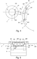
- the 4 and 5 1 shows an embodiment of a support structure arrangement for fastening the aircraft engine 1 to the aircraft 3, wherein the core engine shell 100 of the aircraft engine 1 serves as a supporting structural element.
- the carriers 20 'of the support structure 2 thus extend into the housing 11 of the aircraft engine 1.
- the respective first connecting portion of the carrier 20 is in planar contact with a corresponding connecting portion of the core engine shell 100.
- a connecting device 23 is provided which provides a rigid connection of the carrier 20 'with the supporting structural element, here the core engine sheath 100.
- the support structure assembly further includes an installation frame 22.
- the installation frame 22 may be formed as a so-called space frame.
- the installation frame 22 carries a plurality of accessory components 12A-12C of the aircraft engine 1.
- An accessory component 12A includes a control computer of the aircraft engine 1.
- the control computer is connected by cables to at least one actuator and / or at least one sensor of the aircraft engine 1 within the housing 11.
- An accessory component 12B comprises a transmission of the aircraft engine 1.
- the transmission is, for example, an auxiliary transmission which can be driven by a shaft which is operatively connected to an engine shaft rotatable about the main rotation axis R.
- An accessory component 12C includes a supply device.
- the supply device provides, for example, electric current and / or a fluid to the aircraft engine 1, in particular fuel and / or lubricant.
- the fuel supply can take place via a supply line which extends from the installation space B (eg at least in sections in a straight line) into an area of the core engine 10 facing the installation space B, which allows a particularly short and simple cable routing.
- Each of the accessory components 12A-12C is supported at bearings 220 of the installation frame 22.
- the installation frame 22 is mounted on bearings 202 of the supports 20 'on the supports 20'.
- the installation frame 22 is connected by means of shock absorbers 221 (eg in the form of elastic elements) to the bearings 202 of the supports 20 '.
- shock absorbers 221 eg in the form of elastic elements
- a plurality of accessory components 12A-12C can be jointly protected against vibration, which has a simplified structure allows.
- the installation frame 22 could also be mounted on the aircraft 3 and / or on the aircraft engine 1.
- the use of the installation frame 22 allows multiple accessory components 12A-12C to be assembled and disassembled together. As a result, the maintenance of the aircraft engine 1 can be significantly facilitated.
- the connection of the accessory components 12A-12C to the aircraft engine 1, in particular to the core engine 10, can be provided by means of standardized interfaces for fuel, air, oil and signals.
- the installation frame 22 allows the use of such standardized interfaces.
- the populated installation frame 22 as a whole can be tested, i. Not every accessory component needs to be tested individually, which can reduce qualification and release costs.
- the installation frame 22 as a whole is provided with a thermal insulation which can easily protect a plurality of accessory components 12A-12C from thermal stresses together.
- the aircraft 3 may in particular be a supersonic aircraft.
- Aircraft engines 1 of supersonic aircraft are regularly particularly long, so that in this case with the support structure arrangements described above, a particularly large space B is formed.
Landscapes
- Engineering & Computer Science (AREA)
- Chemical & Material Sciences (AREA)
- Combustion & Propulsion (AREA)
- Mechanical Engineering (AREA)
- General Engineering & Computer Science (AREA)
- Aviation & Aerospace Engineering (AREA)
- Tires In General (AREA)
- Mounting Of Bearings Or Others (AREA)
- Vibration Prevention Devices (AREA)
- Turbine Rotor Nozzle Sealing (AREA)
Abstract
Description
- Die Erfindung betrifft eine Tragstrukturanordnung zur Befestigung eines Flugzeugtriebwerks an einem Flugzeug nach Anspruch 1 und ein Flugzeug.
- Flugzeugtriebwerke werden regelmäßig mittels einem als Tragstruktur dienenden Triebwerkspylon an einem Rumpf oder Flügel eines Flugzeugs befestigt. Um im Betrieb des Flugzeugtriebwerks einwirkenden Kräften und Materialausdehnungen durch Temperaturänderungen Rechnung zu tragen, sind bekannte Flugzeugtriebwerke derart statisch bestimmt am Triebwerkspylon gelagert, dass jede Lagerstelle zumindest einen Freiheitsgrad aufweist. Die
US 9,416,734 B2 - Ein Ziel bei der Entwicklung von Flugzeugen und Flugzeugtriebwerken ist eine Reduzierung des Treibstoffverbrauchs und eine Vergrößerung der Reichweite des Flugzeugs. Dabei spielt der Luftwiderstand des Flugzeugs eine große Rolle. Hierzu tragen auch die Gehäuse der Flugzeugtriebwerke bei. Durch ein Gehäuse mit einer bei gleichbleibender Triebwerksleistung kleineren Querschnittsfläche könnte der Luftwiderstand effektiv reduziert werden.
- Aus der
US 4,068,470 A ist es bekannt, eine Zubehörkomponente des Flugzeugtriebwerks aus der Triebwerksgondel auszulagern und in einem Triebwerkspylon anzuordnen, um so den Querschnitt der Triebwerksgondel zu verringern. Eine weitere Auslagerung von Zubehörkomponenten in den Triebwerkspylon ist mit der beschriebenen Anordnung jedoch nicht ohne weiteres möglich. - Moderne Flugzeugtriebwerke umfassen zudem regelmäßig eine Vielzahl von Zubehörkomponenten, wie etwa ein Steuerungssystem, eine Treibstoffzufuhreinrichtung, ein Zubehörgetriebe und weitere Komponenten. Bisweilen ist es dabei möglich, dass zwischen den Zubehörkomponenten ein ungenutzter Bauraum existiert.
- Es besteht die Aufgabe, eine verbesserte Tragstrukturanordnung bereitzustellen, die es insbesondere ermöglicht, den Luftwiderstand weiter zu reduzieren.
- Die Aufgabe wird durch eine Tragstrukturanordnung mit den Merkmalen des Anspruchs 1 gelöst.
- Danach umfasst eine Tragstrukturanordnung zur Befestigung eines Flugzeugtriebwerks an einem Flugzeug ein tragendes Strukturelement des Flugzeugtriebwerks und eine Tragstruktur. Die Tragstruktur weist zumindest einen Träger und zumindest ein Lager auf. Mittels dem zumindest einen Lager ist der zumindest eine Träger mit dem Flugzeug verbindbar oder verbunden. Es ist vorgesehen, dass der Träger mittels einer (insbesondere vom Lager beabstandeten) Verbindungseinrichtung starr mit dem tragenden Strukturelement des Flugzeugtriebwerks verbindbar oder verbunden ist.
- Mit der Tragstrukturanordnung ist das Flugzeugtriebwerk derart am Flugzeug montiert oder montierbar, dass es statisch bestimmt am Flugzeug gelagert ist. Das montierte Flugzeugtriebwerk ist in allen sechs Freiheitsgraden (drei Rotationsfreiheitsgrade und drei Translationsfreiheitsgrade) am Flugzeug festgelegt.
- Da die Verbindungseinrichtung eine starre Verbindung bereitstellt, kann sie besonders platzsparend ausgeführt werden. Der benötigte Bauraum am Flugzeugtriebwerk kann dadurch deutlich verringert werden. Hierdurch ist es möglich, ein Gehäuse des Flugzeugtriebwerks mit einem kleineren Durchmesser quer zu einer Hauptrotationsachse des Flugzeugtriebwerks auszubilden. Im Ergebnis sind eine verringerte Querschnittsfläche und damit ein wesentlich reduzierter Luftwiderstand erzielbar, wodurch die Reichweite des Flugzeugs gesteigert und/oder der Treibstoffverbrauch des Flugzeugs reduziert werden können.
- Das zumindest eine Lager kann mindestens einen Freiheitsgrad aufweisen, insbesondere genau einen Freiheitsgrad. Insbesondere durch eine flugzeugseitige Lagerung des Trägers oder der Träger mit jeweils zumindest einem Freiheitsgrad pro Lager ist es möglich, den im Betrieb des Flugzeugtriebwerks einwirkenden Kräften und Materialausdehnungen infolge von Temperaturänderungen Rechnung zu tragen. Durch den zumindest einen Freiheitsgrad erlaubt das Lager eine Bewegung zwischen den durch das Lager miteinander verbundenen Komponenten. Als zumindest einen Freiheitsgrad kann das mindestens eine Lager z.B. einen Rotationsfreiheitsgrad (z.B. in Form eines um eine Achse rotierbaren Gleitlagers) und/oder einen Translationsfreiheitsgrad aufweisen.
- Die Tragstrukturanordnung ermöglicht eine Vermeidung von kritischen Schwingformen in Frequenzbereichen, bei denen ansonsten Unwuchtanregungen, insbesondere über längere Zeiträume, auftreten könnten. Hierdurch können sowohl das Gewicht der Tragstrukturanordnung reduziert als auch die Sicherheit erhöht werden.
- Die starre Verbindung des Trägers (oder jedes von mehreren Trägern) mit dem tragenden Strukturelement des Flugzeugtriebwerks durch die Verbindungseinrichtung weist keinen Freiheitsgrad auf. Die Verbindungseinrichtung kann eine lösbare oder eine unlösbare Verbindung bereitstellen. Beispielsweise ist die Verbindungseinrichtung als Flanschverbindung ausgebildet oder umfasst eine Flanschverbindung, insbesondere mit einer Vielzahl von lösbaren Schrauben oder Bolzen. Auch kann die Verbindungseinrichtung als Schwalbenschwanzverbindung ausgebildet sein oder eine Schwalbenschwanzverbindung umfassen. Alternativ kann die Verbindungseinrichtung eine stoffschlüssige Verbindung sein. Zum Beispiel ist die Verbindungseinrichtung eine Schweißverbindung. Mittels der Verbindungseinrichtung können der Träger und das tragende Strukturelement einstückig verbunden sein.
- Das tragende Strukturelement des Flugzeugtriebwerks ist ausgebildet, die übrigen Triebwerksbauteile zu tragen.
- Die Tragstruktur ist z.B. als Triebwerkspylon ausgebildet. Bei dem Flugzeugtriebwerk handelt es sich insbesondere um ein Strahltriebwerk, z.B. um ein Turbofan-Triebwerk.
- Das tragende Strukturelement des Flugzeugtriebwerks ist z.B. ein Teil eines Gehäuses (oder das Gehäuse) oder ein Teil einer Kerntriebwerkshülle (oder die Kerntriebwerkshülle) des Flugzeugtriebwerks.
- In einer Ausgestaltung sind zwei oder mehr Lager vorgesehen, mittels denen der Träger jeweils mit dem Flugzeug verbindbar oder verbunden ist. Jedes dieser Lager weist optional zumindest einen Freiheitsgrad auf, insbesondere jeweils genau einen Freiheitsgrad. Im mit dem Flugzeug mittels der Lager verbundenen Zustand weist das tragende Strukturelement keinen Freiheitsgrad gegenüber dem Flugzeug auf. Auf diese Weise ist eine sichere Befestigung des Flugzeugtriebwerks am Flugzeug möglich, die Ausdehnungen und Kontraktionen infolge von Temperaturänderungen sowie elastische Verformungen infolge von im Betrieb auftretenden Kräften der Bauteile des Flugzeugtriebwerks, der Tragstruktur und des Flugzeugs erlaubt. Beispielsweise sind ein oder mehrere Lager als Bolzenverbindung ausgeführt, die jeweils eine Rotation um eine Achse erlaubt. Die zwei oder mehr Lager sind beabstandet voneinander, insbesondere in einer Richtung parallel zur Hauptrotationsachse des Flugzeugtriebwerks. Bevorzugt sind zumindest drei (insbesondere drei, vier oder sechs) Lager vorgesehen, die insbesondere in (zumindest) zwei Richtungen voneinander beabstandet angeordnet sind.
- Der zumindest eine Träger kann zumindest zwei Lager zur Verbindung des Trägers mit dem Flugzeug aufweisen, deren Abstand zueinander entlang einer direkten Verbindungslinie größer ist, als der minimale Durchmesser der Tragstruktur zwischen dem Flugzeugtriebwerk und dem Flugzeug in einer Richtung parallel zur direkten Verbindungslinie zwischen den zumindest zwei Lagern. Durch die großen Abstände können die zu übertragenden Kräfte reduziert werden. Hierdurch wird eine besonders stabile Anbindung an das Flugzeug ermöglicht. Jedes dieser beiden Lager kann zumindest einen Freiheitsgrad aufweisen, insbesondere genau einen Freiheitsgrad.
- Die Tragstruktur kann zwei oder mehr beabstandete Träger umfassen. Insbesondere können zwei oder mehr Träger axial in Bezug auf die Hauptrotationsachse des Flugzeugtriebwerks beabstandet voneinander sein. Hierdurch, insbesondere bei großen Abständen zwischen den Trägern, ist eine besonders stabile Tragstruktur möglich.
- In einer Weiterbildung ist vorgesehen, dass in einem mit dem Flugzeugtriebwerk verbundenen Zustand der Träger das oder die Lager eines Trägers der zumindest zwei Träger (jeweils) einen Abstand zu dem Lager oder den Lagern eines anderen der zumindest zwei Träger aufweist/aufweisen, der größer ist als eine Länge eines Kerntriebwerks und/oder eines Gehäuses des Flugzeugtriebwerks (in Richtung der Hauptrotationsachse des Flugzeugtriebwerks) und/oder als die Gesamtlänge des Flugzeugtriebwerks in Richtung der Hauptrotationsachse des Flugzeugtriebwerks. Durch die starren Verbindungen kann diese Anordnung demgegenüber eine besonders hohe Stabilität aufweisen.
- Optional ist zumindest eine Zubehörkomponente des Flugzeugtriebwerks zwischen den zumindest zwei insbesondere axial beabstandeten Trägern der Tragstruktur angeordnet. In diesem Zwischenraum zwischen den Trägern kann die Zubehörkomponente besonders platzsparend untergebracht werden. Es muss kein Platz innerhalb des Gehäuses des Flugzeugtriebwerks bereitgestellt werden, sodass das Gehäuse besonders schmal ausgeführt werden kann.
- Zumindest eine Zubehörkomponente kann ein Getriebe, eine Leitungsanordnung, eine Versorgungseinrichtung und/oder einen Steuerungscomputer umfassen. Optional sind im Wesentlichen sämtliche Zubehörkomponenten des Flugzeugtriebwerks im Zwischenraum zwischen den Trägern angeordnet.
- In einer Weiterbildung ist ein zwischen den zumindest zwei (insbesondere axial) beabstandeten Trägern der Tragstruktur angeordneter Installationsrahmen vorgesehen. Optional kann hierbei ein Installationsrahmen vorgesehen werden, wie er in der
US 9,416,734 B2 - Optional ist zumindest ein Stoßdämpfer und/oder Vibrations-Isolator vorgesehen, mittels dem der Installationsrahmen am Flugzeugtriebwerk, an der Befestigungseinrichtung und/oder am Flugzeug gelagert oder lagerbar ist. Hierdurch kann für sämtliche am Installationsrahmen montierten Zubehörkomponenten gemeinsam eine Dämpfung gegen Vibrationen und Erschütterungen bereitgestellt werden. Gegenüber einer jeweils separaten Dämpfung einzelner Zubehörkomponenten ermöglicht dies einen wesentlich einfacheren Aufbau.
- In einer Ausgestaltung umfasst das Lager oder jedes von mehreren Lagern ein elastisches Element (oder allgemein einen Stoßdämpfer). Das elastische Element (oder der Stoßdämpfer) ist im mit dem Flugzeug verbundenen Zustand im Lastpfad angeordnet. Eine auf das Flugzeugtriebwerk einwirkende Kraft fließt somit durch das elastische Element (den Stoßdämpfer) in das Flugzeug. Auf diese Weise können eine Entkoppelung von Schwingungen und ein Ausgleich von Verformungen bereitgestellt werden. Das elastische Element (der Stoßdämpfer) kann den zumindest einen Freiheitsgrad des Lagers bereitstellen. Das elastische Element umfasst beispielsweise ein Gummi und/oder ein Metallgewebe oder besteht daraus.
- Gemäß einem Aspekt wird eine Anordnung bereitgestellt, die eine Tragstrukturanordnung nach einer beliebigen, hierin beschriebenen Ausführung und das Flugzeugtriebwerk umfasst.
- Gemäß einem Aspekt wird ein Flugzeug bereitgestellt. Das Flugzeug umfasst einen Rumpf und zumindest ein Flugzeugtriebwerk. Dabei ist eine Tragstrukturanordnung nach einer beliebigen, hierin beschriebenen Ausführung vorgesehen, wobei das Flugzeugtriebwerk mittels der Tragstruktur der Tragstrukturanordnung am Rumpf des Flugzeugs befestigt ist, und zwar insbesondere im Bereich eines Hecks des Flugzeugs. Ein solches Flugzeug kann einen besonders geringen Luftwiderstand aufweisen. Hierdurch können die Reichweite des Flugzeugs gesteigert und/oder der Treibstoffverbrauch des Flugzeugs reduziert werden.
- Jedes der Lager des einen oder der mehreren Träger kann eine Befestigungsstelle umfassen, die fest mit dem Rumpf des Flugzeugs verbunden ist, und die in einer gegenüber einer äußeren Hülle des Rumpfs des Flugzeugs zurückgesetzten Tasche oder Aussparung angeordnet ist. Hierdurch ist eine weitere Reduzierung des Luftwiderstandes des Flugzeugs möglich. Zudem kann der Raum der Tasche, insbesondere zwischen mehreren Trägern, als zusätzlicher Bauraum für Zubehörkomponenten des Flugzeugtriebwerks verwendet werden. Hierdurch kann der Abstand zwischen dem Flugzeugtriebwerk und dem Flugzeug reduziert werden, was noch eine weitere Reduktion des Luftwiderstandes ermöglicht.
- Gemäß einem Aspekt wird ein Verfahren zur Herstellung einer Tragstrukturanordnung nach einer beliebigen, hierin beschriebenen Ausgestaltung bereitgestellt. Die Tragstruktur umfasst dabei zumindest zwei voneinander beabstandete Träger. Dabei wird mittels einer Topologieoptimierung (insbesondere in einem iterativen Prozess) zumindest eines von einem Abstand der Träger zueinander (z.B. ein minimaler Abstand und/oder ein Abstand zwischen flugzeugseitigen Befestigungsstellen), einer Höhe, Dicke und/oder Breite von jedem der Träger und einer relativen Materialverteilung der Träger ermittelt (z.B. umfasst der vordere Träger zumindest doppelt so viel Material wie der hintere Träger). Die Tragstrukturanordnung wird dementsprechend gefertigt und kann an einem Flugzeug montiert werden.
- Im Zusammenhang mit den in den Figuren dargestellten Ausführungsbeispielen wird die Erfindung erläutert. Dabei zeigen
- Fig. 1
- eine schematische perspektivische Darstellung eines Flugzeugs mit im Bereich eines Hecks des Flugzeugs angeordneten Flugzeugtriebwerken;
- Fig. 2
- eine schematische Querschnittsdarstellung eines Teiles des Flugzeugs gemäß
Fig. 1 mit einem der Flugzeugtriebwerke und mit einer Ausführungsform einer Tragstrukturanordnung; - Fig. 3
- eine schematische Draufsicht auf den in
Fig. 2 gezeigten Teil des Flugzeugs mit dem Flugzeugtriebwerk und der Tragstrukturanordnung; - Fig. 4
- eine schematische Querschnittsdarstellung eines Teiles des Flugzeugs gemäß
Fig. 1 mit einem der Flugzeugtriebwerke und mit einer Ausführungsform einer Tragstrukturanordnung; und - Fig. 5
- eine schematische Draufsicht auf den in
Fig. 4 gezeigten Teil des Flugzeugs mit dem Flugzeugtriebwerk und der Tragstrukturanordnung. -
Fig. 1 zeigt ein Flugzeug 3 mit mehreren Flugzeugtriebwerken, mittels denen das Flugzeug 3 antreibbar ist. Vorliegend umfasst das Flugzeug 3 zwei Flugzeugtriebwerke 1, die jeweils mittels einer Tragstruktur 2 in Form eines Triebwerkspylons am Flugzeug 3 befestigt sind, und ein optionales Hilfstriebwerk 32, das zentral am Heck des Flugzeugs 3 angeordnet ist. - Die beiden jeweils mittels einer Tragstruktur 2 am Flugzeug 3 befestigten Flugzeugtriebwerke 1 sind auf gegenüberliegenden Seiten des Flugzeugs 3 an einem Rumpf 30 des Flugzeugs 3 montiert, vorliegend im Bereich des Hecks des Flugzeugs 3. Alternativ oder zusätzlich können Flugzeugtriebwerke 1 mittels der Tragstruktur 2 auch an Flügeln 31 des Flugzeugs montiert sein.
- Die
Fig. 2 und 3 zeigen verschiedene Ansichten eines der Flugzeugtriebwerke 1 mit dessen am Rumpf 30 des Flugzeugs 3 montierten Tragstruktur 2. - Das Flugzeugtriebwerk 1 umfasst ein Kerntriebwerk 10, in welchem eine Verbrennung von Treibstoff stattfindet. Das Kerntriebwerk 10 umfasst eine Kerntriebwerkshülle 100. Das Kerntriebwerk 10 ist zumindest teilweise von einem äußeren Gehäuse 11 umschlossen. Vorliegend ist das Gehäuse 11 als tragendes Strukturelement ausgebildet, kann also die übrigen Komponenten des Flugzeugtriebwerks 1 tragen. Das Flugzeugtriebwerk 1 ist vorliegend als Strahltriebwerk ausgebildet (z.B. als Turbofan-Triebwerk) und umfasst insbesondere einen Verdichter und eine Turbine, die um eine Hauptrotationsachse R rotierbar sind.
- Zusammen mit dem Gehäuse 11 bildet die Tragstruktur 2 eine Tragstrukturanordnung zur Befestigung des Flugzeugtriebwerks 1 am Flugzeug 3.
- Die Tragstruktur 2 umfasst zwei Träger 20. In der Seitenansicht (siehe insbesondere
Fig. 2 ) weist jeder der Träger 20 im gezeigten Beispiel eine H-Form oder Doppel-T-Form auf, wobei selbstverständlich auch andere Formen möglich sind. - Jeder der Träger 20 umfasst einen ersten Verbindungsabschnitt, der in flächiger Anlage mit einem Verbindungsabschnitt des Gehäuses 11 des Flugzeugtriebwerks 1 steht. Jeder der Träger 20 umfasst mehrere Befestigungsstellen 200 im Bereich des ersten Verbindungsabschnitts. Die Befestigungsstellen 200 sind z.B. Löcher für Schrauben oder Bolzen. An den Verbindungsabschnitten des Gehäuses 11 sind entsprechende Befestigungsstellen ausgebildet. Die Tragstruktur 2 umfasst ferner mehrere Schrauben oder Bolzen, mittels denen die mehreren Befestigungsstellen 200 der Träger 20 mit denen des Gehäuses 11 fest verbunden sind. Hierdurch wird pro Träger 20 jeweils (zumindest) eine Verbindungseinrichtung 23 bereitgestellt, die den Träger 20 starr mit dem Gehäuse 11 verbindet.
- Zwischen dem Träger 20 und dem Gehäuse 11 ist unter bestimmungsgemäßen Betriebsbedingungen des Flugzeugtriebwerks 1 und der Tragstruktur 2 keine Relativbewegung möglich. Durch den Einsatz von Schrauben oder Bolzen (oder anderer lösbarer Verbindungsmittel) ist die Verbindungseinrichtung 23 lösbar. Das Flugzeugtriebwerk 1 kann somit demontiert und/oder montiert werden, ohne dass die Trageinrichtung 2 am Flugzeug 3 montiert und/oder davon demontiert werden muss.
- Alternativ umfasst die Verbindungseinrichtung 23 eine unlösbare Verbindung, z.B. eine Schweißverbindung.
- Der vordere Träger 20 ist z.B. fest mit einem Fangehäuse des Gehäuses 11 verbunden, wobei das Fangehäuse einen Fan des Flugzeugtriebwerks 1 aufnimmt. Der hintere Träger 20 ist optional fest mit einem Teil des Gehäuses 10 im Bereich einer Turbine und/oder einer Düse verbunden. Der vordere Träger 20 ist in einer Ausgestaltung massiver ausgebildet als der hintere Träger 20. Beispielsweise ist der vordere Träger 20 zumindest abschnittsweise größer oder dicker ausgebildet als der hintere Träger 20.
- In einem Verfahren zur Herstellung der Tragstrukturanordnung kann eine topologische Optimierungsmethode angewandt werden, um die Materialverteilung zwischen den Trägern 20 der Tragstrukturanordnung zu ermitteln (z.B. mit dem Resultat, dass der vordere Träger 20 mehr Material aufweist als der hintere Träger 20). Beispielsweise wird dabei eine Pylonhöhe H ermittelt, wie anhand des Pfeils in
Fig. 2 ersichtlich. Daraufhin wird die Tragstrukturanordnung montiert, so wie inFig. 2 gezeigt. - Jeder der Träger 20 umfasst an einer dem ersten Verbindungsabschnitt gegenüberliegenden Seite einen zweiten Verbindungsabschnitt. Über den zweiten Verbindungsabschnitt ist jeder der Träger 20 mit dem Flugzeug 3 verbunden. Hierzu umfasst die Tragstruktur mehrere Lager 21, vorliegend jeweils zwei Lager 21 pro Träger 20.
- Beide Verbindungsabschnitte (die vertikalen Balken der H-Form) von jedem der Träger 20 erstrecken sich entlang des Umfangs des Flugzeugtriebwerks 1 bzw. des Rumpf 30 des Flugzeugs 3. Entlang der jeweiligen Umfangsrichtung ist der zweite Verbindungsabschnitt länger als der erste Verbindungsabschnitt. Dies wird insbesondere durch die starre Verbindung am ersten Verbindungsabschnitt ermöglicht.
- Jedes der Lager 21 weist zumindest einen Freiheitsgrad auf, stellt für sich genommen also keine starre Verbindung bereit.
- Die Träger 20 sind beabstandet voneinander angeordnet, vorliegend in einer Richtung parallel zur Hauptrotationsachse R des Flugzeugtriebwerks 1 (oder parallel zur Zylinderachse des zumindest abschnittsweise zylinderförmigen Gehäuses 11). Wie in
Fig. 3 gezeigt, weisen die Träger 20 einen gebogenen Abschnitt auf, vorliegend einen S-förmig gebogenen Abschnitt. Hierdurch sind der erste und der zweite Verbindungsabschnitt jedes der Träger 20 versetzt zueinander angeordnet. Die Lager 21 des einen Trägers 20 weisen einen Abstand A1 zu den Lagern 21 des anderen Trägers 20 auf. Dieser Abstand A1 ist größer als der Abstand der ersten Verbindungsbereiche der beiden Träger 20 zueinander. Der Abstand A1 ist größer als die Länge L des Flugzeugtriebwerks 1, insbesondere größer als die Länge des Kerntriebwerks 10 und des Gehäuses 11. Der Abstand A1 der Lager 21 des einen Trägers 20 zu denen des anderen Trägers 20 ist somit gegenüber dem Flugzeugtriebwerk 1 axial vergrößert. Durch diesen vergrößerten Abstand A1 können die Kräfte im Betrieb des Flugzeugtriebwerks 1 besonders gut in den Rumpf 30 des Flugzeugs 3 eingeleitet werden. Hierdurch können bei gleichzeitiger Vergrößerung eines Bauraums B zwischen den Trägern 20 (wie weiter unten näher erläutert werden wird) die einwirkenden Kräfte reduziert werden. - Optional weist nur einer der beiden Träger 20, insbesondere der in Flugrichtung betrachtet hintere Träger 20 einen gebogenen Abschnitt auf. Der andere der beiden Träger 20 kann in einer Ansicht senkrecht zur Hauptrotationsrichtung R im Wesentlichen gerade ausgebildet sein.
- Bei jedem der Träger 20 sind die Lager 21 des Trägers 20 voneinander beabstandet, vorliegend in einer Richtung senkrecht zur Hauptrotationsachse R des Flugzeugtriebwerks 1 (oder senkrecht zur Zylinderachse des zumindest abschnittsweise zylinderförmigen Gehäuses 11). Die Lager 21 jedes der Träger 20 weisen einen Abstand A2 zueinander auf. Der Abstand A2 zwischen den Lagern 21 ist größer als der minimale Durchmesser der Tragstruktur 2 zwischen dem Flugzeugtriebwerk 1 und dem Flugzeug 3 in einer Richtung parallel zur direkten Verbindungslinie zwischen den zumindest zwei Lagern 21. Dieser minimale Durchmesser der Tragstruktur 2 entspricht der Pylonhöhe H. Hierdurch wird eine besonders stabile Lagerung der Flugzeugturbine 1 ermöglicht.
- Zwischen den Trägern 20 wird ein Bauraum B aufgespannt oder bereitgestellt. Durch den Abstand der Träger 20 zueinander, den Abstand A1 der Lager 21 des einen Trägers 20 zu den Lagern 21 des anderen Trägers 20 und den Abstand A2 der Lager 21 des jeweiligen Trägers 20 zueinander ist der Bauraum B besonders groß. Zudem können die einwirkenden Kräfte reduziert werden.
- Im Bauraum B können Zubehörkomponenten des Flugzeugtriebwerks 1 angeordnet werden, wie nachfolgend im Zusammenhang mit den
Fig. 4 und 5 noch im Detail erläutert werden wird. Diese müssen somit nicht innerhalb des Gehäuses 11 untergebracht werden, wodurch das Gehäuse 11 einen besonders geringen Querschnitt aufweisen kann. Hierdurch kann der Luftwiderstand des Flugzeugtriebwerks 1 deutlich reduziert werden. - Zudem ist der Bauraum B zwischen dem Flugzeug 3 und dem Flugzeugtriebwerk 1 besonders gut zugänglich, z.B. für Installations- und Wartungsarbeiten.
- Durch eine Anordnung der Zubehörkomponenten im Bauraum B und damit näher am Rumpf 30 des Flugzeugs 3 können die Träger 20 besonders materialsparend ausgebildet werden, was zu einer Gewichtseinsparung führen kann.
- Jedes der Lager 21 umfasst eine am Träger 20 ausgebildete Lagerstelle 201, eine am Flugzeug 3 ausgebildete Befestigungsstelle 330 und ein elastisches Element 210 (oder allgemein ein Dämpfungselement). Das elastische Element 210 ist im Lastpfad oder Kraftfluss zwischen der Lagerstelle 201 des Trägers 20 und der Befestigungsstelle 330 des Flugzeugs 3 angeordnet. So kann das elastische Element 210 Vibrationen dämpfen. Das elastische Element 210 kann den zumindest einen Freiheitsgrad des Lagers bereitstellen. Alternativ oder zusätzlich umfasst das Lager 21 z.B. eine Schwenkverbindung. Hierdurch kann eine thermische Ausdehnung oder Kontraktion des Trägers 21 oder anderer Bauteile gestattet werden, ohne dass es zu Spannungen in den Lagern 21 kommt.
- Wie anhand von
Fig. 2 und 3 veranschaulicht, sind die Befestigungsstellen 330 am Flugzeug 3 nicht außen an einer äußeren Hülle 300 des Rumpfs 30 des Flugzeugs 3 angeordnet, sondern innerhalb einer in der Hülle 300 ausgebildeten Aussparung oder Tasche 301. Die Befestigungsstellen 300 sind somit gegenüber der äußeren Hülle 300 zurückgesetzt (ins Innere des Rumpfs 30). Hierdurch sind die zweiten Verbindungsabschnitte der Träger 20 innerhalb der der Hülle 300 angeordnet (innerhalb einer durchgehend konvexen Form der Hülle 300). Dadurch ist es möglich, den Bauraum B zu vergrößern und/oder den Luftwiderstand gegenüber einer Anordnung außerhalb der Hülle 300 deutlich zu reduzieren oder zumindest nicht zu erhöhen. - Die Befestigungsstellen 330 des Flugzeugs 3 sind an einer tragenden Struktur 33 des Flugzeugs 3 fixiert oder angeformt, z.B. in Form eines tragenden Rahmens des Flugzeugs 3.
- Durch die Tasche 301 kann ferner ein weiter vergrößerter Bauraum B bereitgestellt werden. Der Bauraum B erstreckt sich somit ins Innere des Rumpfs 30. Ein Gehäuse der Tragstrukturanordnung kann den Bauraum B einschließen.
- Die
Fig. 4 und 5 zeigen eine Ausführung einer Tragstrukturanordnung zur Befestigung des Flugzeugtriebwerks 1 am Flugzeug 3, wobei als tragendes Strukturelement die Kerntriebwerkshülle 100 des Flugzeugtriebwerks 1 dient. Die Träger 20' der Tragstruktur 2 erstrecken sich somit in das Gehäuse 11 des Flugzeugtriebwerks 1 hinein. Der jeweilige erste Verbindungsabschnitt der Träger 20 steht in flächiger Anlage mit einem entsprechenden Verbindungsabschnitt der Kerntriebwerkshülle 100. Entsprechend der Ausführung gemäßFig. 2 und 3 ist jeweils eine Verbindungseinrichtung 23 vorgesehen, die eine starre Verbindung des Trägers 20' mit dem tragenden Strukturelement bereitstellt, hier der Kerntriebwerkshülle 100. - Wie insbesondere anhand von
Fig. 5 veranschaulicht, umfasst die Tragstrukturanordnung ferner einen Installationsrahmen 22. Der Installationsrahmen 22 kann als sogenannter Spaceframe ausgebildet sein. Der Installationsrahmen 22 trägt mehrere Zubehörkomponenten 12A-12C des Flugzeugtriebwerks 1. Eine Zubehörkomponente 12A umfasst einen Steuerungscomputer des Flugzeugtriebwerks 1. Der Steuerungscomputer ist durch Kabel mit zumindest einem Stellglied und/oder zumindest einem Sensor des Flugzeugtriebwerks 1 innerhalb des Gehäuses 11 verbunden. Eine Zubehörkomponente 12B umfasst ein Getriebe des Flugzeugtriebwerks 1. Bei dem Getriebe handelt es sich z.B. um ein Hilfsgetriebe, das von einer Welle antreibbar ist, die mit einer um die Hauptrotationsachse R drehbaren Triebwerkswelle wirkverbunden ist. Eine Zubehörkomponente 12C umfasst eine Versorgungseinrichtung. Die Versorgungseinrichtung stellt beispielsweise elektrischen Strom und/oder ein Fluid an das Flugzeugtriebwerk 1 bereit, insbesondere Treibstoff und/oder Schmiermittel. Die Treibstoffzufuhr kann über eine Zufuhrleitung erfolgen, die sich vom Bauraum B (z.B. zumindest abschnittsweise geradlinig) in einen dem Bauraum B zugewandten Bereich des Kerntriebwerks 10 hinein erstreckt, was eine besonders kurze und einfache Leitungsführung erlaubt. - Jede der Zubehörkomponenten 12A-12C ist an Lagerstellen 220 des Installationsrahmens 22 gelagert.
- Der Installationsrahmen 22 ist an Lagerstellen 202 der Träger 20' an den Trägern 20' montiert. Zur Dämpfung von Vibrationen ist der Installationsrahmen 22 mittels Stoßdämpfern 221 (z.B. in Form von elastischen Elementen) an den Lagerstellen 202 der Träger 20' angebunden. Somit können mehrere Zubehörkomponenten 12A-12C gemeinsam gegen Vibrationen geschützt werden, was einen vereinfachten Aufbau ermöglicht. Alternativ oder zusätzlich könnte der Installationsrahmen 22 auch am Flugzeug 3 und/oder am Flugzeugtriebwerk 1 montiert sein.
- Der Einsatz des Installationsrahmens 22 ermöglicht es, dass mehrere Zubehörkomponenten 12A-12C gemeinsam ein- und ausgebaut werden können. Hierdurch kann die Wartung des Flugzeugtriebwerks 1 deutlich erleichtert werden. Der Anschluss der Zubehörkomponenten 12A-12C an das Flugzeugtriebwerk 1, insbesondere an das Kerntriebwerk 10, kann mittels standardisierter Schnittstellen für Treibstoff, Luft, Öl und Signale bereitgestellt werden. Der Installationsrahmen 22 ermöglicht den Einsatz solcher standardisierter Schnittstellen.
- Ferner kann der bestückte Installationsrahmen 22 als Ganzes getestet werden, d.h. nicht jede Zubehörkomponente muss einzeln getestet werden, was Qualifizierungs- und Freigabekosten reduzieren kann.
- Indem die Zubehörkomponenten 12A-12C nicht unmittelbar am Kerntriebwerk 10 angeordnet sind, sondern im Bauraum B, ist es leichter, sie vor hohen Temperaturen im Betrieb des Flugzeugtriebwerks 1 abzuschirmen. Optional ist der Installationsrahmen 22 insgesamt mit einer Wärmeisolierung versehen, die in einfacher Weise mehrere Zubehörkomponenten 12A-12C gemeinsam vor Temperaturbelastungen schützen kann.
- Somit können mit dem Tragen des Flugzeugtriebwerks 1 und der Zubehörkomponenten 12A-12C mehrere Funktionalitäten in die Tragstruktur 2 integriert werden.
- Im Übrigen stimmt die Ausführung der Tragstrukturanordnung gemäß
Fig. 4 und 5 mit der gemäßFig. 2 und 3 überein, sodass auf die diesbezüglichen Ausführungen Bezug genommen wird. Umgekehrt kann auch die Ausführung gemäßFig. 2 und 3 einen Installationsrahmen 22 gemäßFig. 4 und 5 umfassen. - Bei dem Flugzeug 3 kann es sich insbesondere um ein Überschallflugzeug handeln. Flugzeugtriebwerke 1 von Überschallflugzeugen sind regelmäßig besonders lang, sodass in diesem Fall mit den vorstehend beschriebenen Tragstrukturanordnungen ein besonders großer Bauraum B entsteht.
-
- 1
- Flugzeugtriebwerk
- 10
- Kerntriebwerk
- 100
- Kerntriebwerkshülle
- 11
- Gehäuse
- 12A-12C
- Zubehörkomponente
- 2
- Tragstruktur
- 20, 20'
- Träger
- 200
- Befestigungsstelle
- 201
- Lagerstelle
- 202
- Lagerstelle
- 21
- Lager
- 210
- elastisches Element
- 22
- Installationsrahmen
- 220
- Lagerstelle
- 221
- Stoßdämpfer
- 23
- Verbindungseinrichtung
- 3
- Flugzeug
- 30
- Rumpf
- 300
- Hülle
- 301
- Tasche
- 31
- Flügel
- 32
- Hilfstriebwerk
- 33
- tragende Struktur
- 330
- Befestigungsstelle
- A1, A2
- Abstand
- B
- Bauraum
- H
- Pylonhöhe
- L
- Länge
- R
- Hauptrotationsachse
Claims (14)
- Tragstrukturanordnung zur Befestigung eines Flugzeugtriebwerks (1) an einem Flugzeug (3), umfassend:- ein tragendes Strukturelement (100, 11) des Flugzeugtriebwerks (1) und- eine Tragstruktur (2) mit zumindest einem Träger (20, 20') und zumindest einem Lager (21), mittels dem der Träger (20, 20') mit dem Flugzeug (3) verbindbar oder verbunden ist,wobei der Träger (20, 20') mittels einer Verbindungseinrichtung (23) starr mit dem tragenden Strukturelement (100, 11) des Flugzeugtriebwerks (1) verbindbar oder verbunden ist.
- Tragstrukturanordnung nach Anspruch 1, dadurch gekennzeichnet, dass das tragende Strukturelement (100, 11) zumindest ein Teil eines Gehäuses oder zumindest ein Teil einer Kerntriebwerkshülle ist.
- Tragstrukturanordnung nach Anspruch 1 oder 2, dadurch gekennzeichnet, dass zumindest zwei Lager (21) vorgesehen sind, wobei jedes Lager (21) zumindest einen Freiheitsgrad aufweist.
- Tragstrukturanordnung nach einem der vorhergehenden Ansprüche, dadurch gekennzeichnet, dass der zumindest eine Träger (20, 20') zumindest zwei Lager (21) zur Verbindung des Trägers (20, 20') mit dem Flugzeug (3) aufweist, deren Abstand (A2) zueinander größer ist, als der minimale Durchmesser (H) der Tragstruktur (2) zwischen dem Flugzeugtriebwerk (1) und dem Flugzeug (3) in einer Richtung parallel zur direkten Verbindungslinie zwischen den zumindest zwei Lagern (21).
- Tragstrukturanordnung nach einem der vorhergehenden Ansprüche, gekennzeichnet durch zumindest zwei voneinander beabstandete Träger (20, 20') der Tragstruktur (2).
- Tragstrukturanordnung nach Anspruch 5, dadurch gekennzeichnet, dass bei mit dem Flugzeugtriebwerk (1) verbundenen Trägern (20, 20') das zumindest eine Lager (21) eines der zumindest zwei Träger (20, 20') einen Abstand (A1) zu zumindest einem Lager (201) eines anderen der zumindest zwei Träger (20, 20') aufweist, der größer ist als eine Länge (L) eines Kerntriebwerks (10) und/oder eines Gehäuses (11) des Flugzeugtriebwerks (1).
- Tragstrukturanordnung nach Anspruch 5 oder 6, dadurch gekennzeichnet, dass zumindest eine Zubehörkomponente (12A-12C) des Flugzeugtriebwerks (1) zwischen den zumindest zwei axial beabstandeten Trägern (20, 20') der Tragstruktur (2) angeordnet ist.
- Tragstrukturanordnung nach Anspruch 7, dadurch gekennzeichnet, dass zumindest eine Zubehörkomponente (12A-12C) ein Getriebe, eine Leitungsanordnung, eine Versorgungseinrichtung und/oder einen Steuerungscomputer umfasst.
- Tragstrukturanordnung nach Anspruch 7 oder 8, gekennzeichnet durch einen zwischen den zumindest den zwei axial beabstandeten Trägern (20, 20') der Tragstruktur (2) angeordneten Installationsrahmen (22), an dem die zumindest eine Zubehörkomponente (12A-12C) befestigt ist.
- Tragstrukturanordnung nach Anspruch 9, gekennzeichnet durch zumindest einen Stoßdämpfer (221), mittels dem der Installationsrahmen (22) am Flugzeugtriebwerk (1), an der Befestigungseinrichtung (2) und/oder am Flugzeug (3) gelagert oder lagerbar ist.
- Tragstrukturanordnung nach einem der vorhergehenden Ansprüche, dadurch gekennzeichnet, dass das Lager (21) einen Stoßdämpfer und/oder ein elastisches Element (210) umfasst, welcher/welches im mit dem Flugzeug (3) verbundenen Zustand im Lastpfad angeordnet ist.
- Flugzeug (3) mit einem Rumpf (30) und zumindest einem Flugzeugtriebwerk (1), gekennzeichnet durch eine Tragstrukturanordnung nach einem der vorhergehenden Ansprüche, wobei das Flugzeugtriebwerk (1) mittels der Tragstruktur (2) der Tragstrukturanordnung am Rumpf (30) des Flugzeugs (3) befestigt ist.
- Flugzeug (3) nach Anspruch 12, dadurch gekennzeichnet, dass das Lager (21) zumindest eine Befestigungsstelle (330) umfasst, die fest mit dem Rumpf (30) des Flugzeugs (3) verbunden ist, und die in einer gegenüber einer äußeren Hülle (300) des Rumpfs (30) des Flugzeugs (3) zurückgesetzten Tasche (301) angeordnet ist.
- Verfahren zur Herstellung einer Tragstrukturanordnung nach einem der Ansprüche 1 bis 11 mit zumindest zwei voneinander beabstandeten Trägern (20, 20') der Tragstruktur (2), wobei mittels Topologieoptimierung zumindest eines von einem Abstand (A1) zwischen den Trägern (20), einer Höhe (H) von jedem der Träger (20) und einer relativen Materialverteilung der Träger (20) ermittelt wird.
Applications Claiming Priority (1)
| Application Number | Priority Date | Filing Date | Title |
|---|---|---|---|
| DE102017129060.5A DE102017129060A1 (de) | 2017-12-06 | 2017-12-06 | Integrierte Tragstruktur für ein Flugzeugtriebwerk und dessen Zubehörkomponenten |
Publications (2)
| Publication Number | Publication Date |
|---|---|
| EP3495632A1 true EP3495632A1 (de) | 2019-06-12 |
| EP3495632B1 EP3495632B1 (de) | 2021-05-05 |
Family
ID=64661062
Family Applications (1)
| Application Number | Title | Priority Date | Filing Date |
|---|---|---|---|
| EP18209800.4A Active EP3495632B1 (de) | 2017-12-06 | 2018-12-03 | Integrierte tragstruktur für ein flugzeugtriebwerk und dessen zubehörkomponenten |
Country Status (3)
| Country | Link |
|---|---|
| US (1) | US11440669B2 (de) |
| EP (1) | EP3495632B1 (de) |
| DE (1) | DE102017129060A1 (de) |
Families Citing this family (6)
| Publication number | Priority date | Publication date | Assignee | Title |
|---|---|---|---|---|
| GB2580980A (en) * | 2019-02-04 | 2020-08-05 | Airbus Operations Ltd | Interfaces between components |
| FR3106126B1 (fr) * | 2020-01-10 | 2022-01-07 | Safran Aircraft Engines | Assemblage entre un pylône d’aéronef et une turbomachine |
| JP7623867B2 (ja) * | 2021-03-26 | 2025-01-29 | 本田技研工業株式会社 | 航空機 |
| US12221218B2 (en) * | 2022-01-20 | 2025-02-11 | Textron Innovations Inc. | Engine isolation subframe for aircraft |
| US12134988B2 (en) | 2023-01-13 | 2024-11-05 | Pratt & Whitney Canada Corp. | Accessory gearbox cover with planar linking member |
| US20250108909A1 (en) * | 2023-09-29 | 2025-04-03 | Textron Aviation Inc. | Low Drag Nacelle and Pylon Fairing |
Citations (5)
| Publication number | Priority date | Publication date | Assignee | Title |
|---|---|---|---|---|
| US4044973A (en) * | 1975-12-29 | 1977-08-30 | The Boeing Company | Nacelle assembly and mounting structures for a turbofan jet propulsion engine |
| DE2720957A1 (de) * | 1977-05-10 | 1978-11-23 | Willi Klotz | Doppelantrieb fuer motorsegler (motorsegelflugzeug) |
| US5065959A (en) * | 1989-11-21 | 1991-11-19 | The Boeing Company | Vibration damping aircraft engine attachment |
| EP2965991A1 (de) * | 2014-07-10 | 2016-01-13 | Honeywell International Inc. | Verfahren und vorrichtung zur reduzierung hoher, transienter belastungen in flugzeugtriebwerksaufhängungen |
| US20170259928A1 (en) * | 2014-09-16 | 2017-09-14 | Safran Aircraft Engines | Method and device for mounting an engine on an aircraft pylon |
Family Cites Families (15)
| Publication number | Priority date | Publication date | Assignee | Title |
|---|---|---|---|---|
| US4068470A (en) | 1974-11-08 | 1978-01-17 | The United States Of America As Represented By The Administrator Of The National Aeronautics And Space Administration | Gas turbine engine with convertible accessories |
| DE2544272C3 (de) * | 1975-10-03 | 1979-02-22 | Avions Marcel Dassault-Breguet Aviation S.A., Vaucresson (Frankreich) | Triebwerksaufhängung an Luftfahrzeugen |
| US4311289A (en) * | 1978-09-11 | 1982-01-19 | The Dee Howard Company | Modifications to jet aircraft having aft fuselage-mounted nacelles overlapping the wing assemblies |
| US4821980A (en) | 1987-09-29 | 1989-04-18 | The Boeing Company | Vibration isolating engine mount |
| DE3741857C2 (de) * | 1987-12-10 | 1999-05-20 | Klotz Willi | Einklappbare Triebwerke für zweimotorige Flugzeuge der Gewichtsklassen G, I, K und entsprechende militärische Flugzeuge |
| DE3813369C2 (de) * | 1988-04-21 | 1997-01-16 | Schempp Hirth Flugzeugbau Gmbh | Arretiereinrichtung für Propeller von Motorseglern mit Klapptriebwerk |
| FR2775465B1 (fr) | 1998-03-02 | 2000-05-26 | Aerospatiale | Dispositif d'accrochage d'un moteur sur un pylone d'aeronef |
| GB2359052B (en) * | 2000-02-09 | 2003-09-17 | Rolls Royce Plc | Engine arrangement |
| FR2828167B1 (fr) | 2001-07-31 | 2003-11-21 | Airbus France | Dispositif d'accrochage d'un moteur sur un aeronef |
| FR2855495B1 (fr) | 2003-05-27 | 2006-11-24 | Snecma Moteurs | Dispositif d'accrochage avant de moteur d'avion |
| GB201121971D0 (en) | 2011-12-21 | 2012-02-01 | Rolls Royce Deutschland & Co Kg | Accessory mounting for a gas turbine |
| FR3015433B1 (fr) * | 2013-12-23 | 2016-02-12 | Airbus Operations Sas | Ensemble pour aeronef comprenant un mat d'accrochage integre a la nacelle et agence en partie arriere du fuselage |
| JP6450076B2 (ja) * | 2014-02-24 | 2019-01-09 | 三菱航空機株式会社 | 航空機、航空機のエンジンパイロン、および航空機の機体へのエンジン取付方法 |
| FR3047973B1 (fr) * | 2016-02-23 | 2018-03-09 | Airbus Operations | Ensemble moteur pour aeronef, comprenant un dispositif d'accrochage du moteur equipe de capots mobiles structuraux relies au caisson central |
| US10273017B2 (en) * | 2016-03-15 | 2019-04-30 | The Boeing Company | System and method for protecting the structural integrity of an engine strut |
-
2017
- 2017-12-06 DE DE102017129060.5A patent/DE102017129060A1/de not_active Withdrawn
-
2018
- 2018-12-03 EP EP18209800.4A patent/EP3495632B1/de active Active
- 2018-12-05 US US16/210,919 patent/US11440669B2/en active Active
Patent Citations (5)
| Publication number | Priority date | Publication date | Assignee | Title |
|---|---|---|---|---|
| US4044973A (en) * | 1975-12-29 | 1977-08-30 | The Boeing Company | Nacelle assembly and mounting structures for a turbofan jet propulsion engine |
| DE2720957A1 (de) * | 1977-05-10 | 1978-11-23 | Willi Klotz | Doppelantrieb fuer motorsegler (motorsegelflugzeug) |
| US5065959A (en) * | 1989-11-21 | 1991-11-19 | The Boeing Company | Vibration damping aircraft engine attachment |
| EP2965991A1 (de) * | 2014-07-10 | 2016-01-13 | Honeywell International Inc. | Verfahren und vorrichtung zur reduzierung hoher, transienter belastungen in flugzeugtriebwerksaufhängungen |
| US20170259928A1 (en) * | 2014-09-16 | 2017-09-14 | Safran Aircraft Engines | Method and device for mounting an engine on an aircraft pylon |
Also Published As
| Publication number | Publication date |
|---|---|
| EP3495632B1 (de) | 2021-05-05 |
| US11440669B2 (en) | 2022-09-13 |
| DE102017129060A1 (de) | 2019-06-06 |
| US20190168883A1 (en) | 2019-06-06 |
Similar Documents
| Publication | Publication Date | Title |
|---|---|---|
| EP3495632B1 (de) | Integrierte tragstruktur für ein flugzeugtriebwerk und dessen zubehörkomponenten | |
| DE60117931T2 (de) | Gestänge für eine Aufhängevorrichtung eines Flugzeugtriebwerks | |
| DE69221286T2 (de) | Turbinenabstützung | |
| DE69312657T2 (de) | Turbinenrahmen | |
| DE102011057077B4 (de) | Strukturelle Turbinenmantelringvorrichtung geringer Duktilität | |
| DE69511682T2 (de) | Sicherheitseinrichtung für ein Triebwerks-Aufhängungssystem | |
| CH700973B1 (de) | Turbinengehäuse mit innerer und äusserer Gehäuseanordnung befestigt an Biegeknotenstellen. | |
| DE3879605T2 (de) | Schwingungsdaempfungsbefestigung eines triebwerks. | |
| DE3243659C2 (de) | ||
| DE3739941A1 (de) | Schwingungsdaempfende triebwerkshalterung | |
| DE3124462A1 (de) | "anordnung zur lagerung eines rotors, die auch bei eintritt einer dynamischen unwucht einen sicheren weiterlauf des rotors ermoeglicht" | |
| EP3273015B1 (de) | Kalibriervorrichtung zur durchführung eines demontageverfahrens für gasturbinen | |
| EP2332834A2 (de) | Vorrichtung zur Aufhängung eines Strahltriebwerks an einer Stützstruktur | |
| DE102009003604A1 (de) | Innenturbinengehäuse-Lagerungskonfiguration und Verfahren | |
| EP2617979B1 (de) | Enteisungsvorrichtung eines Fluggasturbinentriebwerks | |
| EP2268902B1 (de) | Strebe für ein turbinenzwischengehäuse und turbinenzwischengehäuse | |
| DE102020117254A1 (de) | Gasturbinentriebwerk und Luftfahrzeug mit einem Gasturbinentriebwerk | |
| DE4008432C2 (de) | ||
| WO2008110431A1 (de) | Läufer für eine gasturbine | |
| DE69204453T2 (de) | Brennkammeranordnung. | |
| DE3017035C2 (de) | ||
| EP3176386B1 (de) | Innenringsystem, zugehöriger innenring, zwichengehäuse und strömungsmaschine | |
| EP1666700A2 (de) | Gasturbine | |
| DE19713077B4 (de) | Abstützanordnung für den Ständer einer elektrischen Turbomaschine, insbesondere eines Turbogenerators | |
| EP3327256B1 (de) | Leitschaufelbaugruppe mit ausgleichseinrichtung |
Legal Events
| Date | Code | Title | Description |
|---|---|---|---|
| PUAI | Public reference made under article 153(3) epc to a published international application that has entered the european phase |
Free format text: ORIGINAL CODE: 0009012 |
|
| STAA | Information on the status of an ep patent application or granted ep patent |
Free format text: STATUS: THE APPLICATION HAS BEEN PUBLISHED |
|
| AK | Designated contracting states |
Kind code of ref document: A1 Designated state(s): AL AT BE BG CH CY CZ DE DK EE ES FI FR GB GR HR HU IE IS IT LI LT LU LV MC MK MT NL NO PL PT RO RS SE SI SK SM TR |
|
| AX | Request for extension of the european patent |
Extension state: BA ME |
|
| STAA | Information on the status of an ep patent application or granted ep patent |
Free format text: STATUS: REQUEST FOR EXAMINATION WAS MADE |
|
| 17P | Request for examination filed |
Effective date: 20191210 |
|
| RBV | Designated contracting states (corrected) |
Designated state(s): AL AT BE BG CH CY CZ DE DK EE ES FI FR GB GR HR HU IE IS IT LI LT LU LV MC MK MT NL NO PL PT RO RS SE SI SK SM TR |
|
| GRAP | Despatch of communication of intention to grant a patent |
Free format text: ORIGINAL CODE: EPIDOSNIGR1 |
|
| STAA | Information on the status of an ep patent application or granted ep patent |
Free format text: STATUS: GRANT OF PATENT IS INTENDED |
|
| INTG | Intention to grant announced |
Effective date: 20201125 |
|
| GRAS | Grant fee paid |
Free format text: ORIGINAL CODE: EPIDOSNIGR3 |
|
| GRAA | (expected) grant |
Free format text: ORIGINAL CODE: 0009210 |
|
| STAA | Information on the status of an ep patent application or granted ep patent |
Free format text: STATUS: THE PATENT HAS BEEN GRANTED |
|
| AK | Designated contracting states |
Kind code of ref document: B1 Designated state(s): AL AT BE BG CH CY CZ DE DK EE ES FI FR GB GR HR HU IE IS IT LI LT LU LV MC MK MT NL NO PL PT RO RS SE SI SK SM TR |
|
| REG | Reference to a national code |
Ref country code: GB Ref legal event code: FG4D Free format text: NOT ENGLISH |
|
| REG | Reference to a national code |
Ref country code: CH Ref legal event code: EP |
|
| REG | Reference to a national code |
Ref country code: AT Ref legal event code: REF Ref document number: 1390062 Country of ref document: AT Kind code of ref document: T Effective date: 20210515 |
|
| REG | Reference to a national code |
Ref country code: DE Ref legal event code: R096 Ref document number: 502018005107 Country of ref document: DE |
|
| REG | Reference to a national code |
Ref country code: IE Ref legal event code: FG4D Free format text: LANGUAGE OF EP DOCUMENT: GERMAN |
|
| REG | Reference to a national code |
Ref country code: LT Ref legal event code: MG9D |
|
| PG25 | Lapsed in a contracting state [announced via postgrant information from national office to epo] |
Ref country code: LT Free format text: LAPSE BECAUSE OF FAILURE TO SUBMIT A TRANSLATION OF THE DESCRIPTION OR TO PAY THE FEE WITHIN THE PRESCRIBED TIME-LIMIT Effective date: 20210505 Ref country code: HR Free format text: LAPSE BECAUSE OF FAILURE TO SUBMIT A TRANSLATION OF THE DESCRIPTION OR TO PAY THE FEE WITHIN THE PRESCRIBED TIME-LIMIT Effective date: 20210505 Ref country code: FI Free format text: LAPSE BECAUSE OF FAILURE TO SUBMIT A TRANSLATION OF THE DESCRIPTION OR TO PAY THE FEE WITHIN THE PRESCRIBED TIME-LIMIT Effective date: 20210505 Ref country code: BG Free format text: LAPSE BECAUSE OF FAILURE TO SUBMIT A TRANSLATION OF THE DESCRIPTION OR TO PAY THE FEE WITHIN THE PRESCRIBED TIME-LIMIT Effective date: 20210805 |
|
| PG25 | Lapsed in a contracting state [announced via postgrant information from national office to epo] |
Ref country code: RS Free format text: LAPSE BECAUSE OF FAILURE TO SUBMIT A TRANSLATION OF THE DESCRIPTION OR TO PAY THE FEE WITHIN THE PRESCRIBED TIME-LIMIT Effective date: 20210505 Ref country code: SE Free format text: LAPSE BECAUSE OF FAILURE TO SUBMIT A TRANSLATION OF THE DESCRIPTION OR TO PAY THE FEE WITHIN THE PRESCRIBED TIME-LIMIT Effective date: 20210505 Ref country code: PL Free format text: LAPSE BECAUSE OF FAILURE TO SUBMIT A TRANSLATION OF THE DESCRIPTION OR TO PAY THE FEE WITHIN THE PRESCRIBED TIME-LIMIT Effective date: 20210505 Ref country code: PT Free format text: LAPSE BECAUSE OF FAILURE TO SUBMIT A TRANSLATION OF THE DESCRIPTION OR TO PAY THE FEE WITHIN THE PRESCRIBED TIME-LIMIT Effective date: 20210906 Ref country code: LV Free format text: LAPSE BECAUSE OF FAILURE TO SUBMIT A TRANSLATION OF THE DESCRIPTION OR TO PAY THE FEE WITHIN THE PRESCRIBED TIME-LIMIT Effective date: 20210505 Ref country code: NO Free format text: LAPSE BECAUSE OF FAILURE TO SUBMIT A TRANSLATION OF THE DESCRIPTION OR TO PAY THE FEE WITHIN THE PRESCRIBED TIME-LIMIT Effective date: 20210805 Ref country code: GR Free format text: LAPSE BECAUSE OF FAILURE TO SUBMIT A TRANSLATION OF THE DESCRIPTION OR TO PAY THE FEE WITHIN THE PRESCRIBED TIME-LIMIT Effective date: 20210806 Ref country code: IS Free format text: LAPSE BECAUSE OF FAILURE TO SUBMIT A TRANSLATION OF THE DESCRIPTION OR TO PAY THE FEE WITHIN THE PRESCRIBED TIME-LIMIT Effective date: 20210905 |
|
| REG | Reference to a national code |
Ref country code: NL Ref legal event code: MP Effective date: 20210505 |
|
| PG25 | Lapsed in a contracting state [announced via postgrant information from national office to epo] |
Ref country code: NL Free format text: LAPSE BECAUSE OF FAILURE TO SUBMIT A TRANSLATION OF THE DESCRIPTION OR TO PAY THE FEE WITHIN THE PRESCRIBED TIME-LIMIT Effective date: 20210505 |
|
| PG25 | Lapsed in a contracting state [announced via postgrant information from national office to epo] |
Ref country code: ES Free format text: LAPSE BECAUSE OF FAILURE TO SUBMIT A TRANSLATION OF THE DESCRIPTION OR TO PAY THE FEE WITHIN THE PRESCRIBED TIME-LIMIT Effective date: 20210505 Ref country code: EE Free format text: LAPSE BECAUSE OF FAILURE TO SUBMIT A TRANSLATION OF THE DESCRIPTION OR TO PAY THE FEE WITHIN THE PRESCRIBED TIME-LIMIT Effective date: 20210505 Ref country code: SM Free format text: LAPSE BECAUSE OF FAILURE TO SUBMIT A TRANSLATION OF THE DESCRIPTION OR TO PAY THE FEE WITHIN THE PRESCRIBED TIME-LIMIT Effective date: 20210505 Ref country code: SK Free format text: LAPSE BECAUSE OF FAILURE TO SUBMIT A TRANSLATION OF THE DESCRIPTION OR TO PAY THE FEE WITHIN THE PRESCRIBED TIME-LIMIT Effective date: 20210505 Ref country code: DK Free format text: LAPSE BECAUSE OF FAILURE TO SUBMIT A TRANSLATION OF THE DESCRIPTION OR TO PAY THE FEE WITHIN THE PRESCRIBED TIME-LIMIT Effective date: 20210505 Ref country code: CZ Free format text: LAPSE BECAUSE OF FAILURE TO SUBMIT A TRANSLATION OF THE DESCRIPTION OR TO PAY THE FEE WITHIN THE PRESCRIBED TIME-LIMIT Effective date: 20210505 Ref country code: RO Free format text: LAPSE BECAUSE OF FAILURE TO SUBMIT A TRANSLATION OF THE DESCRIPTION OR TO PAY THE FEE WITHIN THE PRESCRIBED TIME-LIMIT Effective date: 20210505 |
|
| REG | Reference to a national code |
Ref country code: DE Ref legal event code: R097 Ref document number: 502018005107 Country of ref document: DE |
|
| PLBE | No opposition filed within time limit |
Free format text: ORIGINAL CODE: 0009261 |
|
| STAA | Information on the status of an ep patent application or granted ep patent |
Free format text: STATUS: NO OPPOSITION FILED WITHIN TIME LIMIT |
|
| 26N | No opposition filed |
Effective date: 20220208 |
|
| PG25 | Lapsed in a contracting state [announced via postgrant information from national office to epo] |
Ref country code: IS Free format text: LAPSE BECAUSE OF FAILURE TO SUBMIT A TRANSLATION OF THE DESCRIPTION OR TO PAY THE FEE WITHIN THE PRESCRIBED TIME-LIMIT Effective date: 20210905 Ref country code: AL Free format text: LAPSE BECAUSE OF FAILURE TO SUBMIT A TRANSLATION OF THE DESCRIPTION OR TO PAY THE FEE WITHIN THE PRESCRIBED TIME-LIMIT Effective date: 20210505 |
|
| PG25 | Lapsed in a contracting state [announced via postgrant information from national office to epo] |
Ref country code: MC Free format text: LAPSE BECAUSE OF FAILURE TO SUBMIT A TRANSLATION OF THE DESCRIPTION OR TO PAY THE FEE WITHIN THE PRESCRIBED TIME-LIMIT Effective date: 20210505 Ref country code: IT Free format text: LAPSE BECAUSE OF FAILURE TO SUBMIT A TRANSLATION OF THE DESCRIPTION OR TO PAY THE FEE WITHIN THE PRESCRIBED TIME-LIMIT Effective date: 20210505 |
|
| REG | Reference to a national code |
Ref country code: CH Ref legal event code: PL |
|
| REG | Reference to a national code |
Ref country code: BE Ref legal event code: MM Effective date: 20211231 |
|
| PG25 | Lapsed in a contracting state [announced via postgrant information from national office to epo] |
Ref country code: LU Free format text: LAPSE BECAUSE OF NON-PAYMENT OF DUE FEES Effective date: 20211203 Ref country code: IE Free format text: LAPSE BECAUSE OF NON-PAYMENT OF DUE FEES Effective date: 20211203 |
|
| PG25 | Lapsed in a contracting state [announced via postgrant information from national office to epo] |
Ref country code: BE Free format text: LAPSE BECAUSE OF NON-PAYMENT OF DUE FEES Effective date: 20211231 |
|
| PG25 | Lapsed in a contracting state [announced via postgrant information from national office to epo] |
Ref country code: LI Free format text: LAPSE BECAUSE OF NON-PAYMENT OF DUE FEES Effective date: 20211231 Ref country code: CH Free format text: LAPSE BECAUSE OF NON-PAYMENT OF DUE FEES Effective date: 20211231 |
|
| PG25 | Lapsed in a contracting state [announced via postgrant information from national office to epo] |
Ref country code: CY Free format text: LAPSE BECAUSE OF FAILURE TO SUBMIT A TRANSLATION OF THE DESCRIPTION OR TO PAY THE FEE WITHIN THE PRESCRIBED TIME-LIMIT Effective date: 20210505 |
|
| P01 | Opt-out of the competence of the unified patent court (upc) registered |
Effective date: 20230528 |
|
| PG25 | Lapsed in a contracting state [announced via postgrant information from national office to epo] |
Ref country code: HU Free format text: LAPSE BECAUSE OF FAILURE TO SUBMIT A TRANSLATION OF THE DESCRIPTION OR TO PAY THE FEE WITHIN THE PRESCRIBED TIME-LIMIT; INVALID AB INITIO Effective date: 20181203 |
|
| PG25 | Lapsed in a contracting state [announced via postgrant information from national office to epo] |
Ref country code: MK Free format text: LAPSE BECAUSE OF FAILURE TO SUBMIT A TRANSLATION OF THE DESCRIPTION OR TO PAY THE FEE WITHIN THE PRESCRIBED TIME-LIMIT Effective date: 20210505 |
|
| PG25 | Lapsed in a contracting state [announced via postgrant information from national office to epo] |
Ref country code: MT Free format text: LAPSE BECAUSE OF FAILURE TO SUBMIT A TRANSLATION OF THE DESCRIPTION OR TO PAY THE FEE WITHIN THE PRESCRIBED TIME-LIMIT Effective date: 20210505 |
|
| REG | Reference to a national code |
Ref country code: AT Ref legal event code: MM01 Ref document number: 1390062 Country of ref document: AT Kind code of ref document: T Effective date: 20231203 |
|
| PG25 | Lapsed in a contracting state [announced via postgrant information from national office to epo] |
Ref country code: AT Free format text: LAPSE BECAUSE OF NON-PAYMENT OF DUE FEES Effective date: 20231203 |
|
| PG25 | Lapsed in a contracting state [announced via postgrant information from national office to epo] |
Ref country code: TR Free format text: LAPSE BECAUSE OF FAILURE TO SUBMIT A TRANSLATION OF THE DESCRIPTION OR TO PAY THE FEE WITHIN THE PRESCRIBED TIME-LIMIT Effective date: 20210505 |
|
| PGFP | Annual fee paid to national office [announced via postgrant information from national office to epo] |
Ref country code: GB Payment date: 20251223 Year of fee payment: 8 |
|
| PGFP | Annual fee paid to national office [announced via postgrant information from national office to epo] |
Ref country code: FR Payment date: 20251230 Year of fee payment: 8 |
|
| PGFP | Annual fee paid to national office [announced via postgrant information from national office to epo] |
Ref country code: DE Payment date: 20251229 Year of fee payment: 8 |
|
| PGFP | Annual fee paid to national office [announced via postgrant information from national office to epo] |
Ref country code: AT Payment date: 20260410 Year of fee payment: 5 |