EP3495599A1 - Dichtung für ein fenster sowie deren verwendung - Google Patents
Dichtung für ein fenster sowie deren verwendung Download PDFInfo
- Publication number
- EP3495599A1 EP3495599A1 EP18209701.4A EP18209701A EP3495599A1 EP 3495599 A1 EP3495599 A1 EP 3495599A1 EP 18209701 A EP18209701 A EP 18209701A EP 3495599 A1 EP3495599 A1 EP 3495599A1
- Authority
- EP
- European Patent Office
- Prior art keywords
- seal
- profile
- sealing
- sealing head
- window
- Prior art date
- Legal status (The legal status is an assumption and is not a legal conclusion. Google has not performed a legal analysis and makes no representation as to the accuracy of the status listed.)
- Granted
Links
Images

Classifications
-
- E—FIXED CONSTRUCTIONS
- E06—DOORS, WINDOWS, SHUTTERS, OR ROLLER BLINDS IN GENERAL; LADDERS
- E06B—FIXED OR MOVABLE CLOSURES FOR OPENINGS IN BUILDINGS, VEHICLES, FENCES OR LIKE ENCLOSURES IN GENERAL, e.g. DOORS, WINDOWS, BLINDS, GATES
- E06B3/00—Window sashes, door leaves, or like elements for closing wall or like openings; Layout of fixed or moving closures, e.g. windows in wall or like openings; Features of rigidly-mounted outer frames relating to the mounting of wing frames
- E06B3/54—Fixing of glass panes or like plates
- E06B3/58—Fixing of glass panes or like plates by means of borders, cleats, or the like
- E06B3/62—Fixing of glass panes or like plates by means of borders, cleats, or the like of rubber-like elastic cleats
-
- E—FIXED CONSTRUCTIONS
- E06—DOORS, WINDOWS, SHUTTERS, OR ROLLER BLINDS IN GENERAL; LADDERS
- E06B—FIXED OR MOVABLE CLOSURES FOR OPENINGS IN BUILDINGS, VEHICLES, FENCES OR LIKE ENCLOSURES IN GENERAL, e.g. DOORS, WINDOWS, BLINDS, GATES
- E06B7/00—Special arrangements or measures in connection with doors or windows
- E06B7/16—Sealing arrangements on wings or parts co-operating with the wings
- E06B7/22—Sealing arrangements on wings or parts co-operating with the wings by means of elastic edgings, e.g. elastic rubber tubes; by means of resilient edgings, e.g. felt or plush strips, resilient metal strips
- E06B7/23—Plastic, sponge rubber, or like strips or tubes
- E06B7/2305—Plastic, sponge rubber, or like strips or tubes with an integrally formed part for fixing the edging
- E06B7/2307—Plastic, sponge rubber, or like strips or tubes with an integrally formed part for fixing the edging with a single sealing-line or -plane between the wing and the part co-operating with the wing
- E06B7/2309—Plastic, sponge rubber, or like strips or tubes with an integrally formed part for fixing the edging with a single sealing-line or -plane between the wing and the part co-operating with the wing with a hollow sealing part
-
- E—FIXED CONSTRUCTIONS
- E06—DOORS, WINDOWS, SHUTTERS, OR ROLLER BLINDS IN GENERAL; LADDERS
- E06B—FIXED OR MOVABLE CLOSURES FOR OPENINGS IN BUILDINGS, VEHICLES, FENCES OR LIKE ENCLOSURES IN GENERAL, e.g. DOORS, WINDOWS, BLINDS, GATES
- E06B3/00—Window sashes, door leaves, or like elements for closing wall or like openings; Layout of fixed or moving closures, e.g. windows in wall or like openings; Features of rigidly-mounted outer frames relating to the mounting of wing frames
- E06B3/54—Fixing of glass panes or like plates
- E06B3/58—Fixing of glass panes or like plates by means of borders, cleats, or the like
- E06B3/62—Fixing of glass panes or like plates by means of borders, cleats, or the like of rubber-like elastic cleats
- E06B2003/625—Specific form characteristics
- E06B2003/6264—Specific form characteristics hollow
Definitions
- plastic profiles for windows have several seals.
- the glazing gaskets are recognizable from the outside and arranged between the surface element of the window, in particular the insulating glass pane, and the casement or fixed glazing the frame.
- the stop seals have the task to seal the gap between the frame and the sash on the outside and the inside of the window.
- both the stop seals and the glazing gaskets should partially absorb production-related tolerances in the gap and, in the case of stop gaskets, should produce as little as possible, in the case of glazing gaskets, on the other hand, relatively high contact pressure.
- seal geometry has proven to be largely suitable in practice, however, this seal tends when used as a glazing gasket and when used as a stop seal on the hinge side for rolling or curling, ie, the seal is uneven, sometimes undulating with simultaneous pressure and shear stress deformed.
- a seal which has a sealing foot and a sealing head with a hollow chamber, wherein the sealing head comprises a support surface which rests on the respective sash profile or window frame profile, an outside inclined or curved viewing area, a sealing area and the sealing area supporting the support web.
- the sealing head comprises a support surface which rests on the respective sash profile or window frame profile, an outside inclined or curved viewing area, a sealing area and the sealing area supporting the support web.
- the EP 2 265 790 B1 is arranged on the support surface an inclined to the inside, pointing into the hollow chamber support cam, through which the support bar can be supported.
- a disadvantage of the in the EP 2 265 790 B1 described universal seal is seen that this requires a high material usage. In addition, this seal only provides a punctual support of the support bridge.
- the present invention sets in, the object of which is to provide a seal which can be used both as an abutment seal and as a glazing gasket and overcomes the disadvantages of the prior art.
- the present invention is to provide a corresponding profile system and a corresponding window.
- the present invention is to provide a profile system for a window, which comprises at least one frame profile with a stop seal, wherein the stopper seal comprises two connecting portions for particular cohesive connection of the stop seal to the frame profile and a sealing head, wherein the sealing head a viewing area, a sealing area and has a connecting portion, so that the sealing head forms a chamber open on one side, wherein on the sealing area a pointing into the chamber support portion is formed; and at least one sash profile with at least one glazing gasket, wherein the glazing gasket comprises two connection sections for bonding the glazing gasket in particular to the sash profile and a sealing head, wherein the sealing head has a viewing area, a sealing area and a connecting section, so that the sealing head forms a chamber open on one side , where at the sealing area one into the chamber facing support section is formed comprises; and a window comprising a surface element, in particular an insulating glazing, as well as such a profile system.
- the support section has an L-shaped or T-shaped cross section.
- such a geometry of the support section contributes to an increase in the glazing pressure.
- the seal according to the invention is preferably produced from thermoplastic elastomer or flexible PVC (PVC-P), in particular homogeneously from only one component.
- PVC-P flexible PVC
- the support portion of the seal according to the invention has an L-shaped or T-shaped cross-section.
- a geometry of the support section contributes to an increase in the glazing pressure.
- the stop seal and / or the at least one glazing gasket are extruded onto a glare and / or sash profile in the PCE process. This ensures a stable, cohesive connection between the connection sections of the gasket according to the invention and the relevant glare and / or sash profile of the profile system according to the invention.
- the seal according to the invention can also be glued and / or connected under positive locking with the relevant glare and / or sash profile of the profile system according to the invention.
- inventive gasket, the profile system according to the invention and the window and the door according to the invention as well as individual parts thereof can also be produced line by line or layer by layer using a line-building or layer-building manufacturing process (eg 3D printing).
- a line-building or layer-building manufacturing process eg 3D printing
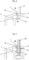
- Fig. 1 is an embodiment of a seal 1 according to the invention, which is extruded onto a profile piece 2 of the profile system according to the invention, shown in a cross-sectional view.
- the seal 1 according to the invention comprises two connection sections 5, 5 ', at which the seal 1 according to the invention is welded to the profile piece 2 by the production according to the PCE method, that is to say is firmly bonded, and a sealing head 6.
- the sealing head 6 contains a viewing region 7 a sealing portion 8 and a connecting portion 9, so that the sealing head 6 is a unilaterally open chamber 10, which is open in the direction of the Dichtungsfactnut 11 forms.
- the sealing head 6 comprises a support portion 12 which is integrally formed on the sealing region 6 and in the unilaterally open chamber 10 has.
- the viewing area 7 adjoins the first connection section 5, which is inclined to the outer side 13, which in turn adjoins a bend 14 of the sealing region 8 which is trough-shaped in the illustrated embodiment, wherein the depression is in the direction of of the profile piece 2 extends.
- the adjoining the sealing portion 8 connecting portion 9 is slightly inclined to the profile piece 2 and formed slightly wavy.
- the second connection portion 5 ' connects.
- a support portion 12 which faces into the open-sided chamber 10 and in the in Fig. 1 illustrated embodiment has an approximately T-shaped cross-section.
- the top of the T-shaped support portion 11 extends to approximately parallel to the wall of the profile piece 2, in which the opening of the Dichtungsfactnut 11 is located and is opposite to this.
- a contact section 16 is integrally formed on the connecting section 9.
- the seal 1 according to the invention is in the post-coextrusion (PCE process) of soft PVC (PVC-P) to the profile piece 2 of rigid PVC (PVC-U) is extruded, wherein the connection sections 5, 5 'with the contact surfaces of the profile piece 2 are materially connected.
- PCE process post-coextrusion
- Fig. 2 shows a cross-sectional view of an embodiment of a window 17 according to the invention in the closed state, comprising a frame profile 3 with a stop seal 18, a sash profile 4 with a glazing gasket 19 and as a surface element 20 an insulating glazing with two glass panes.
- the gap between the frame profile 3 and sash profile 4 is 3.1 mm
- the gap between the surface element 20 and the outer arc of the sash profile 4 is only 1.4 mm.
- Fig. 3 is an enlarged detail from Fig. 2 represented, from which the use of the seal 1 according to the invention as glazing gasket 19 emerges. Due to the small gap between the surface element 20 and the outer arc of the sash profile 4 of only 1.4 mm, the T-shaped support portion 12 is pressed against the wall of the sash profile 4, in which the opening of the Dichtungsfactnut 11 is located, and lies flat against this , Due to the high glazing pressure, the viewing area 7 is strongly inclined to the outside 13, whereas the sealing area 8, which is formed in the shape of a trough in the free state of the seal 1 according to the invention, rests flat against the surface element 20. The end of the abutment portion 16 is at this low gap on the surface element 20, whereby the sealing effect is improved.
- Fig. 4 an enlarged detail is off Fig. 2 shown, from which the use of the seal 1 according to the invention as an abutment seal 18 emerges.
- the gap between frame profile 3 and sash profile 4 amounts to 3.1 mm.
- the T-shaped support portion 12 is indeed pressed in the direction of the wall of the profile piece 2, in which the opening of the Dichtungsfactnut 11 is located, but remains in the illustrated embodiment spaced therefrom.
- the viewing area 7 is less inclined to the outside 13 and the sealing area 8 lies flat against the Surface element 20 at.
- the end of the contact section 16 remains at a distance from the frame profile 3.
- the same gasket geometry can be used both as a stop gasket 18 and as a glazing gasket 19.
- the seal 1 according to the invention is pressed only in the direction of the frame profile 3 so far that the support section 12 does not touch the wall of the frame profile 3 or exerts only a small supporting force in flat contact.
- the support portion 12 is strongly pressed against the wall of the sash profile 4 and compressed when using the seal 1 according to the invention as a glazing gasket 19.
- the glazing pressure when using the seal 1 according to the invention as a glazing gasket 19 is considerably higher than the contact pressure when used as a stop seal 18th
Landscapes
- Engineering & Computer Science (AREA)
- Civil Engineering (AREA)
- Structural Engineering (AREA)
- Securing Of Glass Panes Or The Like (AREA)
- Specific Sealing Or Ventilating Devices For Doors And Windows (AREA)
Abstract
Description
- Die vorliegende Erfindung betrifft eine Dichtung für ein Fenster, die zwei Anschlussabschnitte zum insbesondere stoffschlüssigen Anschluss der Dichtung an ein Blendrahmenprofil oder ein Flügelrahmenprofil für das Fenster, und einen Dichtungskopf, wobei der Dichtungskopf einen Sichtbereich, einen Dichtungsbereich sowie einen Verbindungsabschnitt aufweist, so dass der Dichtungskopf eine einseitig offene Kammer bildet, umfasst. Darüber hinaus betrifft die vorliegende Erfindung ein Profilsystem für ein Fenster, das mindestens ein Blendrahmenprofil mit einer derartigen Dichtung als Anschlagdichtung und mindestens ein Flügelrahmenprofil mit mindestens einer derartigen Dichtung als Verglasungsdichtung umfasst, sowie ein Fenster, das ein derartiges Profilsystem umfasst.
- Grundsätzlich besitzen Kunststoffprofile für Fenster mehrere Dichtungen. Dabei unterscheidet man insbesondere Anschlagdichtungen und Verglasungsdichtungen. Die Verglasungsdichtungen sind von außen erkennbar und zwischen dem Flächenelement des Fensters, insbesondere der Isolierglasscheibe, und dem Flügelrahmen bzw. bei Festverglasungen dem Blendrahmen angeordnet. Die Anschlagdichtungen haben dagegen die Aufgabe, den Spalt zwischen dem Blendrahmen und dem Flügelrahmen auf der Außenseite und der Innenseite des Fensters abzudichten. Daneben sollen sowohl die Anschlagdichtungen als auch die Verglasungsdichtungen teilweise herstellungsbedingte Toleranzen im Spaltmaß aufnehmen und im Fall von Anschlagdichtungen möglichst geringe, im Fall von Verglasungsdichtungen dagegen relativ hohe Anpressdrücke erzeugen.
- Im Stand der Technik ist bekannt, sowohl Anschlagdichtungen als auch Verglasungsdichtungen als weichelastische Dichtungen auszubilden, die unter Verwendung eines entsprechenden Dichtungsfußes in Dichtungsaufnahmenuten des Blendrahmens oder des Flügelrahmens eingerollt oder eingedrückt werden. In jüngerer Zeit werden diese eingerollten oder eingedrückten Dichtungen in wachsendem Umfang durch anextrudierte Dichtungen aus weichelastischem, thermoplastischem Material ersetzt. Dabei kommt in der Regel ein sogenanntes Post-Coextrusionsverfahren (PCE) zum Einsatz. Bei einem solchen PCE-Verfahren wird die jeweilige Dichtung inline an die extrudierten und schon kalibrierten Blendrahmen- und Flügelrahmenprofile anextrudiert.
- Aufgrund der unterschiedlichen Anforderungen an Verglasungsdichtungen einerseits und Anschlagdichtungen andererseits hinsichtlich Anpressdruck und abzudichtendem Spaltmaß kommen in der Regel für Verglasungsdichtungen und Anschlagdichtungen Dichtungsprofile mit unterschiedlichen Profilgeometrien zum Einsatz. Daher gibt es Tendenzen, sogenannte Universaldichtungen einzusetzen, also Dichtungen, die sowohl als Anschlagdichtung als auch als Verglasungsdichtung eingesetzt werden können. Ein solche Universaldichtung ist beispielsweise in der
DE 197 20 940 B4 beschrieben. Bei der in derDE 197 20 940 B4 offenbarten Universaldichtung handelt es sich um eine anextrudierte Dichtung, die mit identischer Geometrie sowohl als Anschlagdichtung als auch als Verglasungsdichtung fungieren kann. Die Dichtungsgeometrie hat sich zwar in der Praxis als weitgehend geeignet erwiesen, allerdings neigt diese Dichtung beim Einsatz als Verglasungsdichtung sowie beim Einsatz als Anschlagdichtung an der Bandseite zum Krempeln oder Einrollen, d. h., die Dichtung wird bei gleichzeitiger Druck- und Scherbeanspruchung ungleichmäßig, zum Teil wellenförmig deformiert. - Um diesen Nachteil zu beheben, wird in der
EP 2 265 790 B1 eine Dichtung vorgeschlagen, die einen Dichtungsfuß und einen Dichtungskopf mit eine Hohlkammer aufweist, wobei der Dichtungskopf eine Auflagefläche, die am jeweiligen Flügelrahmenprofil oder Blendrahmenprofil anliegt, einen zur Außenseite geneigten oder gebogenen Sichtbereich, einen Dichtbereich und einen den Dichtbereich abstützenden Stützsteg umfasst. Gemäß derEP 2 265 790 B1 ist an der Auflagefläche ein zur Innenseite geneigter, in die Hohlkammer weisender Stütznocken angeordnet, durch den der Stützsteg gestützt werden kann. Nachteilig an der in derEP 2 265 790 B1 beschriebenen Universaldichtung wird gesehen, dass diese einen hohen Materialeinsatz erfordert. Darüber hinaus bietet diese Dichtung lediglich eine punktuelle Unterstützung des Stützstegs. - An dieser Stelle setzt die vorliegende Erfindung ein, deren Aufgabe darin liegt, eine Dichtung zur Verfügung zu stellen, die sowohl als Anschlagdichtung als auch als Verglasungsdichtung eingesetzt werden kann und die Nachteile des Stands der Technik überwindet. Darüber hinaus liegt die vorliegende Erfindung in der Bereitstellung eines entsprechenden Profilsystems und eines entsprechenden Fensters.
- Diese und andere Aufgaben werden durch eine Dichtung mit den Merkmalen des Anspruchs 1, durch ein Profilsystem mit den Merkmalen des Anspruchs 5 sowie durch ein Fenster mit den Merkmalen des Anspruchs 9 gelöst. Bevorzugte Ausführungsformen der vorliegenden Erfindung sind jeweils in den abhängigen Ansprüchen beschrieben.
- Gemäß der vorliegenden Erfindung wurde erkannt, dass eine homogenere Verteilung des durch die Dichtung auf das jeweilige Profil ausgeübten Anpressdrucks dadurch erfolgen kann, dass an einen Dichtungsbereich der Dichtung ein Stützabschnitt angeformt ist, der in die durch die Dichtung gebildete, einseitig offene Kammer gerichtet ist. Der Stützabschnitt kann sich somit flächig gegen eine Profilwand des mit der Dichtung versehenen Profils stützen und so zu einer flächigen Aufnahme des durch die Dichtung ausgeübten Anpressdrucks beitragen. Darüber hinaus erfordert eine derartige Dichtung weder einen Dichtungsfuß noch eine weitere Anlagefläche der Dichtung an dem damit versehenen Profil mehr, so dass die Dichtung zu einer erheblichen Materialeinsparung führt.
- Dementsprechend liegt die vorliegende Erfindung in der Bereitstellung einer Dichtung für ein Fenster, die zwei Anschlussabschnitte zum insbesondere stoffschlüssigen Anschluss der Dichtung an ein Blendrahmenprofil oder ein Flügelrahmenprofil für das Fenster; und einen Dichtungskopf, wobei der Dichtungskopf einen Sichtbereich, einen Dichtungsbereich sowie einen Verbindungsabschnitt aufweist, so dass der Dichtungskopf eine einseitig offene Kammer bildet, umfasst, wobei an den Dichtungsbereich ein in die Kammer weisender Stützabschnitt angeformt ist. Darüber hinaus liegt die vorliegende Erfindung in der Bereitstellung eines Profilsystems für ein Fenster, das mindestens ein Blendrahmenprofil mit einer Anschlagdichtung, wobei die Anschlagsdichtung zwei Anschlussabschnitte zum insbesondere stoffschlüssigen Anschluss der Anschlagsdichtung an das Blendrahmenprofil und einen Dichtungskopf umfasst, wobei der Dichtungskopf einen Sichtbereich, einen Dichtungsbereich sowie einen Verbindungsabschnitt aufweist, so dass der Dichtungskopf eine einseitig offene Kammer bildet, wobei an den Dichtungsbereich ein in die Kammer weisender Stützabschnitt angeformt ist; und mindestens ein Flügelrahmenprofil mit mindestens einer Verglasungsdichtung, wobei die Verglasungsdichtung zwei Anschlussabschnitte zum insbesondere stoffschlüssigen Anschluss der Verglasungsdichtung an das Flügelrahmenprofil und einen Dichtungskopf umfasst, wobei der Dichtungskopf einen Sichtbereich, einen Dichtungsbereich sowie einen Verbindungsabschnitt aufweist, so dass der Dichtungskopf eine einseitig offene Kammer bildet, wobei an den Dichtungsbereich ein in die Kammer weisender Stützabschnitt angeformt ist, umfasst; sowie eines Fensters, das ein Flächenelement, insbesondere eine Isolierverglasung, sowie ein derartiges Profilsystem umfasst.
- Die erfindungsgemäße Dichtung kann als Universaldichtung sowohl als Anschlagdichtung als auch als Verglasungsdichtung eingesetzt werden. Beim Einsatz als Anschlagdichtung liegt das Spaltmaß zwischen Blendrahmen und Flügelrahmen bevorzugt im Bereich von 3 mm bis 4 mm und beim Einsatz als Verglasungsdichtung liegt das Spaltmaß bevorzugt im Bereich von 0,7 mm bis 1,5 mm, wird also geringer gewählt.
- Wie hierin verwendet, bezeichnet der Begriff "Außenseite" der Dichtung die bei geschlossenem Fenster von außen sichtbare Kante der Dichtung, während die "Innenseite" der Dichtung bei einer Verglasungsdichtung nicht und bei einer Anschlagdichtung nur bei geöffnetem Fenster sichtbar ist.
- In Bezug auf die erfindungsgemäße Dichtung ist es bevorzugt, wenn der Stützabschnitt einen L-Förmigen oder T-förmigen Querschnitt aufweist. Eine derartige Geometrie des Stützabschnitts trägt beim Einsatz als Verglasungsdichtung zu einer Erhöhung des Verglasungsdrucks bei.
- Es kann auch bevorzugt sein, wenn der Verbindungsabschnitt zur Innenseite geneigt ist. Auf diese Weise wird materialsparend eine Verbindung zwischen dem Dichtungsbereich und dem zweiten Anschlussabschnitt der erfindungsgemäßen Dichtung hergestellt. Zusätzlich oder alternativ dazu kann der Verbindungsabschnitt wellenförmig ausgebildet sein. Dadurch können weitere Stellen erzeugt werden, an denen die erfindungsgemäße Dichtung bei ihrer Verwendung als Verglasungsdichtung an dem Flächenelement anliegt. Dies sorgt für eine verbesserte Dichtungswirkung.
- Es kann auch günstig sein, wenn an den der Verbindungsabschnitt ein Anlageabschnitt angeformt ist. Auch diese Maßnahme sorgt für weitere Stellen, an denen die erfindungsgemäße Dichtung bei ihrer Verwendung als Verglasungsdichtung an dem Flächenelement anliegt und damit für eine weiter verbesserte Dichtungswirkung.
- Bevorzugt wird die erfindungsgemäße Dichtung aus thermoplastischem Elastomer oder Weich-PVC (PVC-P) hergestellt, insbesondere homogen aus nur einer Komponente. Hinsichtlich des erfindungsgemäßen Profilsystems ist es günstig, wenn die Anschlagsdichtung und die Verglasungsdichtung den gleichen Querschnitt aufweisen. Dadurch wird der Charakter der erfindungsgemäßen Dichtung als Universaldichtung erhöht.
- Auch in Bezug auf das erfindungsgemäße Profilsystem ist es bevorzugt, wenn der Stützabschnitt der erfindungsgemäßen Dichtung einen L-Förmigen oder T-förmigen Querschnitt aufweist. Eine derartige Geometrie des Stützabschnitts trägt beim Einsatz als Verglasungsdichtung zu einer Erhöhung des Verglasungsdrucks bei.
- Alternativ oder zusätzlich dazu sind in bevorzugten Ausführungsformen die Anschlagsdichtung und/oder die wenigstens eine Verglasungsdichtung an ein Blend- und/oder Flügelrahmenprofil im PCE-Verfahren anextrudiert. Dies sorgt für eine stabile, stoffschlüssige Verbindung zwischen den Anschlussabschnitten der erfindungsgemäßen Dichtung und dem betreffenden Blend- und/oder Flügelrahmenprofil des erfindungsgemäßen Profilsystems. Alternativ oder zusätzlich dazu kann die erfindungsgemäße Dichtung auch verklebt und/oder unter Formschluss mit dem betreffenden Blend- und/oder Flügelrahmenprofil des erfindungsgemäßen Profilsystems verbunden sein.
- Die erfindungsgemäße Dichtung, das erfindungsgemäße Profilsystem sowie das erfindungsgemäße Fenster und die erfindungsgemäße Tür sowie einzelne Teile davon können auch zeilenweise oder schichtweise unter Verwendung eines zeilenaufbauenden oder schichtaufbauenden Fertigungsverfahrens (z. B. 3D-Druck) hergestellt werden.
- Im Folgenden soll die vorliegende Erfindung unter Bezugnahme auf die in den Figuren dargestellte Ausführungsform im Detail erläutert werden. Insoweit sich Teile oder Bauelemente in ihrer Funktion entsprechen, wird deren Beschreibung nicht in jeder der folgenden Figuren wiederholt. Es zeigen:
- Fig. 1
- eine Ausführungsform der erfindungsgemäßen Dichtung, die an ein Profilstück des erfindungsgemäßen Profilsystem anextrudiert ist, in einer Querschnittsdarstellung;
- Fig. 2
- einen Querschnitt eines Fensters mit erfindungsgemäßer Anschlag- und Verglasungsdichtung in einer Querschnittsdarstellung;
- Fig. 3
- einen vergrößerten Detailausschnitt aus
Fig. 2 , aus dem die Verwendung der erfindungsgemäßen Dichtung als Verglasungssdichtung hervorgeht; und - Fig. 4
- einen vergrößerten Detailausschnitt aus
Fig. 2 , aus dem die Verwendung der erfindungsgemäßen Dichtung als Anschlagsdichtung hervorgeht; - In
Fig. 1 ist eine Ausführungsform einer erfindungsgemäßen Dichtung 1, die an ein Profilstück 2 des erfindungsgemäßen Profilsystems anextrudiert ist, in einer Querschnittsdarstellung gezeigt. Bei dem Profilstück 2 handelt es sich um einen Abschnitt eines Blendrahmenprofils 3 oder eines Flügelrahmenprofils 4 des erfindungsgemäßen Profilsystems. Die erfindungsgemäße Dichtung 1 umfasst zwei Anschlussabschnitte 5, 5', an denen die erfindungsgemäße Dichtung 1 mit dem Profilstück 2 durch die Herstellung nach dem PCE-Verfahren verschweißt ist, also stoffschlüssig verbunden ist, und einen Dichtungskopf 6. Der Dichtungskopf 6 beinhaltet einen Sichtbereich 7, einen Dichtungsbereich 8 sowie einen Verbindungsabschnitt 9, so dass der Dichtungskopf 6 eine einseitig offene Kammer 10, die in Richtung der Dichtungsaufnahmenut 11 offen ist, bildet. Darüber hinaus umfasst der Dichtungskopf 6 einen Stützabschnitt 12, der an den Dichtungsbereich 6 angeformt ist und in die einseitig offene Kammer 10 weist. - Dabei schließt sich in der erfindungsgemäßen Dichtung 1 an den ersten Anschlussabschnitt 5 der Sichtbereich 7 an, der zur Außenseite 13 geneigt ist, an den sich wiederum über eine Biegung 14 der in der dargestellten Ausführungsform muldenförmig ausgebildete Dichtungsbereich 8 anschließt, wobei sich die Mulde in Richtung des Profilstücks 2 erstreckt. Der sich an den Dichtungsabschnitt 8 anschließende Verbindungsabschnitt 9 ist leicht zum Profilstück 2 hin geneigt und leicht wellenförmig ausgebildet. An diesen Verbindungsabschnitt 9 schließt sich der zweite Anschlussabschnitt 5' an.
- Etwa in der Mitte des Dichtungsbereichs 8 ist an den an den Dichtungsbereich 8 ein Stützabschnitt 12 angeformt, der in die einseitig offene Kammer 10 weist und in der in
Fig. 1 dargestellten Ausführungsform einen in etwa T-förmigen Querschnitt aufweist. Die Oberseite des T-förmigen Stützabschnitts 11 verläuft dazu in etwa parallel zur der Wand des Profilstücks 2, in der sich die Öffnung der Dichtungsaufnahmenut 11 befindet und liegt dieser gegenüber. Zur Außenseite 15 hin ist an den Verbindungsabschnitt 9 ein Anlageabschnitt 16 angeformt. - Die erfindungsgemäße Dichtung 1 ist im Post-Coextrusionsverfahren (PCE-Verfahren) aus Weich-PVC (PVC-P) an das Profilstück 2 aus Hart-PVC (PVC-U) anextrudiert, wobei die Anschlussabschnitte 5, 5' mit den Kontaktflächen des Profilstücks 2 stoffschlüssig verbunden sind.
-
Fig. 2 zeigt in einer Querschnittsdarstellung eine Ausführungsform eines erfindungsgemäßen Fensters 17 im geschlossenen Zustand, das ein Blendrahmenprofil 3 mit einer Anschlagdichtung 18, ein Flügelrahmenprofil 4 mit einer Verglasungsdichtung 19 sowie als Flächenelement 20 eine Isolierverglasung mit zwei Glasscheiben umfasst. In der dargestellten Ausführungsform des erfindungsgemäßen Fensters 17 beträgt das Spaltmaß zwischen Blendrahmenprofil 3 und Flügelrahmenprofil 4 beträgt 3,1 mm, das Spaltmaß zwischen dem Flächenelement 20 und dem Außenüberschlag des Flügelrahmenprofils 4 beträgt hingegen nur 1,4 mm. - In
Fig. 3 ist ein vergrößerter Detailausschnitt ausFig. 2 dargestellt, aus dem die Verwendung der erfindungsgemäßen Dichtung 1 als Verglasungsdichtung 19 hervorgeht. Aufgrund des geringen Spaltmaßes zwischen dem Flächenelement 20 und dem Außenüberschlag des Flügelrahmenprofils 4 von lediglich 1,4 mm wird der T-förmigen Stützabschnitt 12 gegen Wand des Flügelrahmenprofils 4 gedrückt, in der sich die Öffnung der Dichtungsaufnahmenut 11 befindet, und liegt flächig an dieser an. Der Sichtbereich 7 ist aufgrund des hohen Verglasungsdrucks stark zur Außenseite 13 geneigt, während der im freien Zustand der erfindungsgemäßen Dichtung 1 muldenförmig ausgebildete Dichtungsbereich 8 flächig an dem Flächenelement 20 anliegt. Das Ende des Anlageabschnitts 16 liegt bei diesem niedrigen Spaltmaß an dem Flächenelement 20 an, wodurch die Dichtwirkung verbessert wird. - In
Fig. 4 hingegen ist ein vergrößerter Detailausschnitt ausFig. 2 dargestellt, aus dem die Verwendung der erfindungsgemäßen Dichtung 1 als Anschlagsdichtung 18 hervorgeht. Hier beläuft sich das Spaltmaß zwischen Blendrahmenprofil 3 und Flügelrahmenprofil 4 auf 3,1 mm. Dadurch wird der T-förmige Stützabschnitt 12 zwar in Richtung der Wand des Profilstücks 2 gedrückt, in der sich die Öffnung der Dichtungsaufnahmenut 11 befindet, bleibt jedoch in der dargestellten Ausführungsform von dieser beabstandet. Der Sichtbereich 7 ist weniger stark zur Außenseite 13 geneigt und der Dichtungsbereich 8 liegt flächig an dem Flächenelement 20 an. Das Ende des Anlageabschnitts 16 bleibt vom Blendrahmenprofil 3 beabstandet. - Unter Einsatz der erfindungsgemäßen Dichtung 1 kann dieselbe Dichtungsgeometrie sowohl als Anschlagdichtung 18 als auch als Verglasungsdichtung 19 verwendet werden. Bei der Verwendung als Anschlagdichtung 18 wird die erfindungsgemäße Dichtung 1 nur soweit in Richtung des Blendrahmenprofils 3 gedrückt, dass der Stützabschnitt 12 die Wand des Blendrahmenprofils 3 nicht berührt oder bei flächiger Anlage nur eine geringe Stützkraft ausübt. Dagegen wird der der Stützabschnitt 12 beim Einsatz der der erfindungsgemäßen Dichtung 1 als Verglasungsdichtung 19 stark gegen die Wand des Flügelrahmenprofils 4 gedrückt und gestaucht. Auf diese Weise ist der Verglasungsdruck beim Einsatz der erfindungsgemäßen Dichtung 1 als Verglasungsdichtung 19 erheblich höher als der Anpressdruck beim Einsatz als Anschlagdichtung 18.
- Die vorliegende Erfindung wurde unter Bezugnahme auf die in den Figuren gezeigte Ausführungsform der vorliegenden Erfindung beschrieben. Es versteht sich, dass die vorliegende Erfindung nicht auf die gezeigte Ausführungsform beschränkt ist; der Umfang der vorliegenden Erfindung ergibt sich vielmehr aus den beiliegenden Ansprüchen.
Claims (10)
- Dichtung (1) für ein Fenster (17), umfassend- zwei Anschlussabschnitte (5, 5') zum insbesondere stoffschlüssigen Anschluss der Dichtung (1) an ein Blendrahmenprofil (3) oder ein Flügelrahmenprofil (4) für das Fenster (16); und- einen Dichtungskopf (6), wobei der Dichtungskopf (6) einen Sichtbereich (7), einen Dichtungsbereich (8) sowie einen Verbindungsabschnitt (9) aufweist, so dass der Dichtungskopf (6) eine einseitig offene Kammer (10) bildet,dadurch gekennzeichnet, dass
an den Dichtungsbereich (8) ein in die Kammer (10) weisender Stützabschnitt (12) angeformt ist. - Dichtung (1) nach Anspruch 1, dadurch gekennzeichnet, dass der Stützabschnitt (12) einen L-Förmigen oder T-förmigen Querschnitt aufweist.
- Dichtung (1) nach Anspruch 1 oder Anspruch 2, dadurch gekennzeichnet, dass der Verbindungsabschnitt (9) zur Innenseite (15) geneigt ist.
- Dichtung (1) nach einem der Ansprüche 1 bis 3, dadurch gekennzeichnet, dass an den der Verbindungsabschnitt (9) ein Anlageabschnitt (16) angeformt ist.
- Profilsystem für ein Fenster (17), umfassend:mindestens ein Blendrahmenprofil (3) mit einer Anschlagdichtung (18), wobei die Anschlagsdichtung (18) zwei Anschlussabschnitte (5, 5') zum insbesondere stoffschlüssigen Anschluss der Anschlagsdichtung (18) an das Blendrahmenprofil (3) und einen Dichtungskopf (6) umfasst, wobei der Dichtungskopf (6) einen Sichtbereich (7), einen Dichtungsbereich (8) sowie einen Verbindungsabschnitt (9) aufweist, so dass der Dichtungskopf (2) eine einseitig offene Kammer (10) bildet, wobei an den Dichtungsbereich (8) ein in die Kammer (10) weisender Stützabschnitt (12) angeformt ist; undmindestens ein Flügelrahmenprofil (4) mit mindestens einer Verglasungsdichtung (19), wobei die Verglasungsdichtung (19) zwei Anschlussabschnitte (5, 5') zum insbesondere stoffschlüssigen Anschluss der Verglasungsdichtung (19) an das Flügelrahmenprofil (4) und einen Dichtungskopf (6) umfasst, wobei der Dichtungskopf (6) einen Sichtbereich (7), einen Dichtungsbereich (8) sowie einen Verbindungsabschnitt (9) aufweist, so dass der Dichtungskopf (6) eine einseitig offene Kammer (10) bildet, wobei an den Dichtungsbereich (8) ein in die Kammer (10) weisender Stützabschnitt (12) angeformt ist.
- Profilsystem nach Anspruch 5, dadurch gekennzeichnet, dass die Anschlagsdichtung (18) und die Verglasungsdichtung (19) den gleichen Querschnitt aufweisen.
- Profilsystem nach Anspruch 8 oder Anspruch 9, dadurch gekennzeichnet, dass der Stützabschnitt (12) einen L-Förmigen oder T-förmigen Querschnitt aufweist.
- Profilsystem nach einem der Ansprüche 5 bis 7, dadurch gekennzeichnet, dass die Anschlagsdichtung (18) und/oder die wenigstens eine Verglasungsdichtung (19) im PCE-Verfahren anextrudiert sind.
- Fenster (17), umfassend ein Flächenelement (20), insbesondere eine Isolierverglasung, sowie ein Profilsystem nach einem der Ansprüche 5 bis 8.
- Fenster (17) nach Anspruch 9, dadurch gekennzeichnet, dass der Stützabschnitt (12) an einer dem Dichtungsbereich (8) der Verglasungsdichtung (19) gegenüberliegenden Wand des Flügelrahmenprofils (4) anliegt.
Applications Claiming Priority (1)
| Application Number | Priority Date | Filing Date | Title |
|---|---|---|---|
| DE202017107394.7U DE202017107394U1 (de) | 2017-12-05 | 2017-12-05 | Dichtung für ein Fenster sowie deren Verwendung |
Publications (2)
| Publication Number | Publication Date |
|---|---|
| EP3495599A1 true EP3495599A1 (de) | 2019-06-12 |
| EP3495599B1 EP3495599B1 (de) | 2021-03-24 |
Family
ID=64572139
Family Applications (1)
| Application Number | Title | Priority Date | Filing Date |
|---|---|---|---|
| EP18209701.4A Not-in-force EP3495599B1 (de) | 2017-12-05 | 2018-12-03 | Dichtung für ein fenster sowie deren verwendung |
Country Status (2)
| Country | Link |
|---|---|
| EP (1) | EP3495599B1 (de) |
| DE (1) | DE202017107394U1 (de) |
Citations (4)
| Publication number | Priority date | Publication date | Assignee | Title |
|---|---|---|---|---|
| DE19506246A1 (de) * | 1995-02-23 | 1996-08-29 | Saar Gummiwerk Gmbh | Profildichtung für große Spaltweiten |
| DE19720940A1 (de) * | 1997-05-20 | 1998-11-26 | Huels Troisdorf | Fenster- oder Türprofil mit anextrudierter Dichtung |
| EP2265790A1 (de) * | 2008-02-20 | 2010-12-29 | Profine Gmbh | Dichtung für fenster- oder türprofile |
| GB2513947A (en) * | 2013-02-13 | 2014-11-12 | Rehau Ltd | Gasket |
Family Cites Families (3)
| Publication number | Priority date | Publication date | Assignee | Title |
|---|---|---|---|---|
| GB2251260B (en) * | 1990-11-16 | 1994-10-12 | Scholes Ernest M H | Sealing arrangement |
| FR2906833B1 (fr) * | 2006-10-04 | 2013-07-05 | Rehau Sa | Joint d'etancheite pour menuiserie, adaptable a une rainure de montage de largeur variable |
| DE202016104415U1 (de) * | 2016-08-11 | 2017-11-14 | Rehau Ag + Co | Elastisches Anschlagdichtungsprofil und dieses umfassende(s) Fenster oder Tür |
-
2017
- 2017-12-05 DE DE202017107394.7U patent/DE202017107394U1/de not_active Expired - Lifetime
-
2018
- 2018-12-03 EP EP18209701.4A patent/EP3495599B1/de not_active Not-in-force
Patent Citations (4)
| Publication number | Priority date | Publication date | Assignee | Title |
|---|---|---|---|---|
| DE19506246A1 (de) * | 1995-02-23 | 1996-08-29 | Saar Gummiwerk Gmbh | Profildichtung für große Spaltweiten |
| DE19720940A1 (de) * | 1997-05-20 | 1998-11-26 | Huels Troisdorf | Fenster- oder Türprofil mit anextrudierter Dichtung |
| EP2265790A1 (de) * | 2008-02-20 | 2010-12-29 | Profine Gmbh | Dichtung für fenster- oder türprofile |
| GB2513947A (en) * | 2013-02-13 | 2014-11-12 | Rehau Ltd | Gasket |
Also Published As
| Publication number | Publication date |
|---|---|
| DE202017107394U1 (de) | 2019-03-06 |
| EP3495599B1 (de) | 2021-03-24 |
Similar Documents
| Publication | Publication Date | Title |
|---|---|---|
| EP2265790B1 (de) | Dichtung für fenster- oder türprofile | |
| EP3634796B1 (de) | Dichtungsanordnung | |
| DE3716214A1 (de) | Strangfoermiges dichtungsprofil | |
| WO2007096108A1 (de) | Gerahmtes flächenelement sowie rahmenprofil für ein derartiges gerahmtes flächentragelement | |
| EP2000623A2 (de) | Verbindungsprofil | |
| DE4201340C1 (en) | Elastomeric sealing strip for windows - has co-extruded double layer with softer base surface and sealing lips and harder supporting shell extending across base surface and part of lips | |
| EP2603658A1 (de) | Fenster | |
| DE202007016186U1 (de) | Elastische Profildichtung | |
| DE4220604A1 (de) | Strangförmiges Dichtungsprofil | |
| DE19847955A1 (de) | Dichtungsprofil für Fenster oder Türen | |
| EP3495599B1 (de) | Dichtung für ein fenster sowie deren verwendung | |
| EP2792520B1 (de) | Dichtungsprofil und Türanordnung mit einem solchen Dichtungsprofil | |
| EP3216967B1 (de) | Dichtungsprofil für fenster, türen oder fassaden | |
| AT404965B (de) | Glasfalzdichtung, insbesondere für fenster und türen | |
| EP3502402A1 (de) | Glasfalzeinlage sowie diese umfassender fenster- oder türflügel | |
| DE20206520U1 (de) | Vorrichtung zur Bildung einer flexiblen Verbindung | |
| EP0470603A1 (de) | Dichtungsleiste zum Abdichten von Tür- und Fensterrahmen oder dgl. Bauteilen | |
| DE2755321A1 (de) | Dichtungsstreifen fuer fenster oder tueren | |
| EP3502403B1 (de) | Fenster- oder türprofil | |
| DE3337438A1 (de) | Profilleiste | |
| DE3239395A1 (de) | Profilleiste | |
| DE102013204944B4 (de) | Elastische Strangdichtung für Fenster, Türen oder dgl. | |
| EP2453094A2 (de) | Silikonband zum elastischen Verschliessen von Fugen | |
| DE9402689U1 (de) | Anschlagdichtung | |
| EP3502404A1 (de) | Fenster- oder türprofil |
Legal Events
| Date | Code | Title | Description |
|---|---|---|---|
| PUAI | Public reference made under article 153(3) epc to a published international application that has entered the european phase |
Free format text: ORIGINAL CODE: 0009012 |
|
| STAA | Information on the status of an ep patent application or granted ep patent |
Free format text: STATUS: THE APPLICATION HAS BEEN PUBLISHED |
|
| AK | Designated contracting states |
Kind code of ref document: A1 Designated state(s): AL AT BE BG CH CY CZ DE DK EE ES FI FR GB GR HR HU IE IS IT LI LT LU LV MC MK MT NL NO PL PT RO RS SE SI SK SM TR |
|
| AX | Request for extension of the european patent |
Extension state: BA ME |
|
| STAA | Information on the status of an ep patent application or granted ep patent |
Free format text: STATUS: REQUEST FOR EXAMINATION WAS MADE |
|
| 17P | Request for examination filed |
Effective date: 20191204 |
|
| RBV | Designated contracting states (corrected) |
Designated state(s): AL AT BE BG CH CY CZ DE DK EE ES FI FR GB GR HR HU IE IS IT LI LT LU LV MC MK MT NL NO PL PT RO RS SE SI SK SM TR |
|
| GRAP | Despatch of communication of intention to grant a patent |
Free format text: ORIGINAL CODE: EPIDOSNIGR1 |
|
| STAA | Information on the status of an ep patent application or granted ep patent |
Free format text: STATUS: GRANT OF PATENT IS INTENDED |
|
| RAP1 | Party data changed (applicant data changed or rights of an application transferred) |
Owner name: REHAU AG + CO |
|
| RIC1 | Information provided on ipc code assigned before grant |
Ipc: E06B 3/62 20060101ALI20201023BHEP Ipc: E06B 7/23 20060101AFI20201023BHEP |
|
| INTG | Intention to grant announced |
Effective date: 20201111 |
|
| GRAS | Grant fee paid |
Free format text: ORIGINAL CODE: EPIDOSNIGR3 |
|
| GRAA | (expected) grant |
Free format text: ORIGINAL CODE: 0009210 |
|
| STAA | Information on the status of an ep patent application or granted ep patent |
Free format text: STATUS: THE PATENT HAS BEEN GRANTED |
|
| AK | Designated contracting states |
Kind code of ref document: B1 Designated state(s): AL AT BE BG CH CY CZ DE DK EE ES FI FR GB GR HR HU IE IS IT LI LT LU LV MC MK MT NL NO PL PT RO RS SE SI SK SM TR |
|
| REG | Reference to a national code |
Ref country code: GB Ref legal event code: FG4D Free format text: NOT ENGLISH |
|
| REG | Reference to a national code |
Ref country code: CH Ref legal event code: EP |
|
| REG | Reference to a national code |
Ref country code: IE Ref legal event code: FG4D Free format text: LANGUAGE OF EP DOCUMENT: GERMAN |
|
| REG | Reference to a national code |
Ref country code: AT Ref legal event code: REF Ref document number: 1374676 Country of ref document: AT Kind code of ref document: T Effective date: 20210415 Ref country code: DE Ref legal event code: R096 Ref document number: 502018004423 Country of ref document: DE |
|
| REG | Reference to a national code |
Ref country code: LT Ref legal event code: MG9D |
|
| PG25 | Lapsed in a contracting state [announced via postgrant information from national office to epo] |
Ref country code: NO Free format text: LAPSE BECAUSE OF FAILURE TO SUBMIT A TRANSLATION OF THE DESCRIPTION OR TO PAY THE FEE WITHIN THE PRESCRIBED TIME-LIMIT Effective date: 20210624 Ref country code: BG Free format text: LAPSE BECAUSE OF FAILURE TO SUBMIT A TRANSLATION OF THE DESCRIPTION OR TO PAY THE FEE WITHIN THE PRESCRIBED TIME-LIMIT Effective date: 20210624 Ref country code: HR Free format text: LAPSE BECAUSE OF FAILURE TO SUBMIT A TRANSLATION OF THE DESCRIPTION OR TO PAY THE FEE WITHIN THE PRESCRIBED TIME-LIMIT Effective date: 20210324 Ref country code: FI Free format text: LAPSE BECAUSE OF FAILURE TO SUBMIT A TRANSLATION OF THE DESCRIPTION OR TO PAY THE FEE WITHIN THE PRESCRIBED TIME-LIMIT Effective date: 20210324 Ref country code: GR Free format text: LAPSE BECAUSE OF FAILURE TO SUBMIT A TRANSLATION OF THE DESCRIPTION OR TO PAY THE FEE WITHIN THE PRESCRIBED TIME-LIMIT Effective date: 20210625 |
|
| PG25 | Lapsed in a contracting state [announced via postgrant information from national office to epo] |
Ref country code: SE Free format text: LAPSE BECAUSE OF FAILURE TO SUBMIT A TRANSLATION OF THE DESCRIPTION OR TO PAY THE FEE WITHIN THE PRESCRIBED TIME-LIMIT Effective date: 20210324 Ref country code: RS Free format text: LAPSE BECAUSE OF FAILURE TO SUBMIT A TRANSLATION OF THE DESCRIPTION OR TO PAY THE FEE WITHIN THE PRESCRIBED TIME-LIMIT Effective date: 20210324 Ref country code: LV Free format text: LAPSE BECAUSE OF FAILURE TO SUBMIT A TRANSLATION OF THE DESCRIPTION OR TO PAY THE FEE WITHIN THE PRESCRIBED TIME-LIMIT Effective date: 20210324 |
|
| REG | Reference to a national code |
Ref country code: NL Ref legal event code: MP Effective date: 20210324 |
|
| PG25 | Lapsed in a contracting state [announced via postgrant information from national office to epo] |
Ref country code: NL Free format text: LAPSE BECAUSE OF FAILURE TO SUBMIT A TRANSLATION OF THE DESCRIPTION OR TO PAY THE FEE WITHIN THE PRESCRIBED TIME-LIMIT Effective date: 20210324 |
|
| PG25 | Lapsed in a contracting state [announced via postgrant information from national office to epo] |
Ref country code: SM Free format text: LAPSE BECAUSE OF FAILURE TO SUBMIT A TRANSLATION OF THE DESCRIPTION OR TO PAY THE FEE WITHIN THE PRESCRIBED TIME-LIMIT Effective date: 20210324 Ref country code: EE Free format text: LAPSE BECAUSE OF FAILURE TO SUBMIT A TRANSLATION OF THE DESCRIPTION OR TO PAY THE FEE WITHIN THE PRESCRIBED TIME-LIMIT Effective date: 20210324 Ref country code: CZ Free format text: LAPSE BECAUSE OF FAILURE TO SUBMIT A TRANSLATION OF THE DESCRIPTION OR TO PAY THE FEE WITHIN THE PRESCRIBED TIME-LIMIT Effective date: 20210324 Ref country code: LT Free format text: LAPSE BECAUSE OF FAILURE TO SUBMIT A TRANSLATION OF THE DESCRIPTION OR TO PAY THE FEE WITHIN THE PRESCRIBED TIME-LIMIT Effective date: 20210324 |
|
| PG25 | Lapsed in a contracting state [announced via postgrant information from national office to epo] |
Ref country code: IS Free format text: LAPSE BECAUSE OF FAILURE TO SUBMIT A TRANSLATION OF THE DESCRIPTION OR TO PAY THE FEE WITHIN THE PRESCRIBED TIME-LIMIT Effective date: 20210724 Ref country code: RO Free format text: LAPSE BECAUSE OF FAILURE TO SUBMIT A TRANSLATION OF THE DESCRIPTION OR TO PAY THE FEE WITHIN THE PRESCRIBED TIME-LIMIT Effective date: 20210324 Ref country code: SK Free format text: LAPSE BECAUSE OF FAILURE TO SUBMIT A TRANSLATION OF THE DESCRIPTION OR TO PAY THE FEE WITHIN THE PRESCRIBED TIME-LIMIT Effective date: 20210324 Ref country code: PL Free format text: LAPSE BECAUSE OF FAILURE TO SUBMIT A TRANSLATION OF THE DESCRIPTION OR TO PAY THE FEE WITHIN THE PRESCRIBED TIME-LIMIT Effective date: 20210324 Ref country code: PT Free format text: LAPSE BECAUSE OF FAILURE TO SUBMIT A TRANSLATION OF THE DESCRIPTION OR TO PAY THE FEE WITHIN THE PRESCRIBED TIME-LIMIT Effective date: 20210726 |
|
| REG | Reference to a national code |
Ref country code: DE Ref legal event code: R097 Ref document number: 502018004423 Country of ref document: DE |
|
| PG25 | Lapsed in a contracting state [announced via postgrant information from national office to epo] |
Ref country code: ES Free format text: LAPSE BECAUSE OF FAILURE TO SUBMIT A TRANSLATION OF THE DESCRIPTION OR TO PAY THE FEE WITHIN THE PRESCRIBED TIME-LIMIT Effective date: 20210324 Ref country code: DK Free format text: LAPSE BECAUSE OF FAILURE TO SUBMIT A TRANSLATION OF THE DESCRIPTION OR TO PAY THE FEE WITHIN THE PRESCRIBED TIME-LIMIT Effective date: 20210324 Ref country code: AL Free format text: LAPSE BECAUSE OF FAILURE TO SUBMIT A TRANSLATION OF THE DESCRIPTION OR TO PAY THE FEE WITHIN THE PRESCRIBED TIME-LIMIT Effective date: 20210324 |
|
| PLBE | No opposition filed within time limit |
Free format text: ORIGINAL CODE: 0009261 |
|
| STAA | Information on the status of an ep patent application or granted ep patent |
Free format text: STATUS: NO OPPOSITION FILED WITHIN TIME LIMIT |
|
| PG25 | Lapsed in a contracting state [announced via postgrant information from national office to epo] |
Ref country code: SI Free format text: LAPSE BECAUSE OF FAILURE TO SUBMIT A TRANSLATION OF THE DESCRIPTION OR TO PAY THE FEE WITHIN THE PRESCRIBED TIME-LIMIT Effective date: 20210324 |
|
| 26N | No opposition filed |
Effective date: 20220104 |
|
| REG | Reference to a national code |
Ref country code: DE Ref legal event code: R081 Ref document number: 502018004423 Country of ref document: DE Owner name: REHAU INDUSTRIES SE & CO. KG, DE Free format text: FORMER OWNER: REHAU AG + CO, 95111 REHAU, DE |
|
| PG25 | Lapsed in a contracting state [announced via postgrant information from national office to epo] |
Ref country code: IS Free format text: LAPSE BECAUSE OF FAILURE TO SUBMIT A TRANSLATION OF THE DESCRIPTION OR TO PAY THE FEE WITHIN THE PRESCRIBED TIME-LIMIT Effective date: 20210724 |
|
| PG25 | Lapsed in a contracting state [announced via postgrant information from national office to epo] |
Ref country code: MC Free format text: LAPSE BECAUSE OF FAILURE TO SUBMIT A TRANSLATION OF THE DESCRIPTION OR TO PAY THE FEE WITHIN THE PRESCRIBED TIME-LIMIT Effective date: 20210324 |
|
| REG | Reference to a national code |
Ref country code: CH Ref legal event code: PL |
|
| REG | Reference to a national code |
Ref country code: BE Ref legal event code: MM Effective date: 20211231 |
|
| PG25 | Lapsed in a contracting state [announced via postgrant information from national office to epo] |
Ref country code: LU Free format text: LAPSE BECAUSE OF NON-PAYMENT OF DUE FEES Effective date: 20211203 Ref country code: IE Free format text: LAPSE BECAUSE OF NON-PAYMENT OF DUE FEES Effective date: 20211203 |
|
| PG25 | Lapsed in a contracting state [announced via postgrant information from national office to epo] |
Ref country code: FR Free format text: LAPSE BECAUSE OF NON-PAYMENT OF DUE FEES Effective date: 20211231 Ref country code: BE Free format text: LAPSE BECAUSE OF NON-PAYMENT OF DUE FEES Effective date: 20211231 |
|
| PG25 | Lapsed in a contracting state [announced via postgrant information from national office to epo] |
Ref country code: LI Free format text: LAPSE BECAUSE OF NON-PAYMENT OF DUE FEES Effective date: 20211231 Ref country code: CH Free format text: LAPSE BECAUSE OF NON-PAYMENT OF DUE FEES Effective date: 20211231 |
|
| PG25 | Lapsed in a contracting state [announced via postgrant information from national office to epo] |
Ref country code: IT Free format text: LAPSE BECAUSE OF FAILURE TO SUBMIT A TRANSLATION OF THE DESCRIPTION OR TO PAY THE FEE WITHIN THE PRESCRIBED TIME-LIMIT Effective date: 20210324 |
|
| PGFP | Annual fee paid to national office [announced via postgrant information from national office to epo] |
Ref country code: DE Payment date: 20221231 Year of fee payment: 5 |
|
| PG25 | Lapsed in a contracting state [announced via postgrant information from national office to epo] |
Ref country code: CY Free format text: LAPSE BECAUSE OF FAILURE TO SUBMIT A TRANSLATION OF THE DESCRIPTION OR TO PAY THE FEE WITHIN THE PRESCRIBED TIME-LIMIT Effective date: 20210324 |
|
| PG25 | Lapsed in a contracting state [announced via postgrant information from national office to epo] |
Ref country code: HU Free format text: LAPSE BECAUSE OF FAILURE TO SUBMIT A TRANSLATION OF THE DESCRIPTION OR TO PAY THE FEE WITHIN THE PRESCRIBED TIME-LIMIT; INVALID AB INITIO Effective date: 20181203 |
|
| GBPC | Gb: european patent ceased through non-payment of renewal fee |
Effective date: 20221203 |
|
| PG25 | Lapsed in a contracting state [announced via postgrant information from national office to epo] |
Ref country code: GB Free format text: LAPSE BECAUSE OF NON-PAYMENT OF DUE FEES Effective date: 20221203 |
|
| PG25 | Lapsed in a contracting state [announced via postgrant information from national office to epo] |
Ref country code: MK Free format text: LAPSE BECAUSE OF FAILURE TO SUBMIT A TRANSLATION OF THE DESCRIPTION OR TO PAY THE FEE WITHIN THE PRESCRIBED TIME-LIMIT Effective date: 20210324 |
|
| REG | Reference to a national code |
Ref country code: DE Ref legal event code: R119 Ref document number: 502018004423 Country of ref document: DE |
|
| PG25 | Lapsed in a contracting state [announced via postgrant information from national office to epo] |
Ref country code: MT Free format text: LAPSE BECAUSE OF FAILURE TO SUBMIT A TRANSLATION OF THE DESCRIPTION OR TO PAY THE FEE WITHIN THE PRESCRIBED TIME-LIMIT Effective date: 20210324 |
|
| PG25 | Lapsed in a contracting state [announced via postgrant information from national office to epo] |
Ref country code: DE Free format text: LAPSE BECAUSE OF NON-PAYMENT OF DUE FEES Effective date: 20240702 |
|
| PG25 | Lapsed in a contracting state [announced via postgrant information from national office to epo] |
Ref country code: DE Free format text: LAPSE BECAUSE OF NON-PAYMENT OF DUE FEES Effective date: 20240702 |
|
| REG | Reference to a national code |
Ref country code: AT Ref legal event code: MM01 Ref document number: 1374676 Country of ref document: AT Kind code of ref document: T Effective date: 20231203 |
|
| PG25 | Lapsed in a contracting state [announced via postgrant information from national office to epo] |
Ref country code: AT Free format text: LAPSE BECAUSE OF NON-PAYMENT OF DUE FEES Effective date: 20231203 |
|
| PG25 | Lapsed in a contracting state [announced via postgrant information from national office to epo] |
Ref country code: TR Free format text: LAPSE BECAUSE OF FAILURE TO SUBMIT A TRANSLATION OF THE DESCRIPTION OR TO PAY THE FEE WITHIN THE PRESCRIBED TIME-LIMIT Effective date: 20210324 |
|
| PGFP | Annual fee paid to national office [announced via postgrant information from national office to epo] |
Ref country code: AT Payment date: 20260410 Year of fee payment: 5 |